EP1316481A2 - Precrash Bedrohungbewertungssystem in einem Crashdetektionssytem - Google Patents
Precrash Bedrohungbewertungssystem in einem Crashdetektionssytem Download PDFInfo
- Publication number
- EP1316481A2 EP1316481A2 EP02102649A EP02102649A EP1316481A2 EP 1316481 A2 EP1316481 A2 EP 1316481A2 EP 02102649 A EP02102649 A EP 02102649A EP 02102649 A EP02102649 A EP 02102649A EP 1316481 A2 EP1316481 A2 EP 1316481A2
- Authority
- EP
- European Patent Office
- Prior art keywords
- safety device
- host
- target
- vehicle
- threshold
- Prior art date
- Legal status (The legal status is an assumption and is not a legal conclusion. Google has not performed a legal analysis and makes no representation as to the accuracy of the status listed.)
- Withdrawn
Links
- 238000001514 detection method Methods 0.000 title description 12
- 230000004913 activation Effects 0.000 claims abstract description 24
- 238000012544 monitoring process Methods 0.000 claims abstract description 7
- 238000000034 method Methods 0.000 claims description 15
- 230000003213 activating effect Effects 0.000 claims description 4
- 230000001419 dependent effect Effects 0.000 claims 1
- 238000001914 filtration Methods 0.000 description 10
- 230000001133 acceleration Effects 0.000 description 8
- 238000010586 diagram Methods 0.000 description 4
- 238000013459 approach Methods 0.000 description 3
- 238000012545 processing Methods 0.000 description 3
- 230000009466 transformation Effects 0.000 description 3
- 230000003044 adaptive effect Effects 0.000 description 2
- 238000011156 evaluation Methods 0.000 description 2
- 230000003466 anti-cipated effect Effects 0.000 description 1
- 238000004364 calculation method Methods 0.000 description 1
- 238000007598 dipping method Methods 0.000 description 1
- 230000000694 effects Effects 0.000 description 1
- 238000005516 engineering process Methods 0.000 description 1
- 230000000977 initiatory effect Effects 0.000 description 1
- 230000000116 mitigating effect Effects 0.000 description 1
- 238000000844 transformation Methods 0.000 description 1
Images

Classifications
-
- B—PERFORMING OPERATIONS; TRANSPORTING
- B60—VEHICLES IN GENERAL
- B60R—VEHICLES, VEHICLE FITTINGS, OR VEHICLE PARTS, NOT OTHERWISE PROVIDED FOR
- B60R21/00—Arrangements or fittings on vehicles for protecting or preventing injuries to occupants or pedestrians in case of accidents or other traffic risks
- B60R21/01—Electrical circuits for triggering passive safety arrangements, e.g. airbags, safety belt tighteners, in case of vehicle accidents or impending vehicle accidents
- B60R21/013—Electrical circuits for triggering passive safety arrangements, e.g. airbags, safety belt tighteners, in case of vehicle accidents or impending vehicle accidents including means for detecting collisions, impending collisions or roll-over
- B60R21/0134—Electrical circuits for triggering passive safety arrangements, e.g. airbags, safety belt tighteners, in case of vehicle accidents or impending vehicle accidents including means for detecting collisions, impending collisions or roll-over responsive to imminent contact with an obstacle, e.g. using radar systems
-
- G—PHYSICS
- G01—MEASURING; TESTING
- G01S—RADIO DIRECTION-FINDING; RADIO NAVIGATION; DETERMINING DISTANCE OR VELOCITY BY USE OF RADIO WAVES; LOCATING OR PRESENCE-DETECTING BY USE OF THE REFLECTION OR RERADIATION OF RADIO WAVES; ANALOGOUS ARRANGEMENTS USING OTHER WAVES
- G01S13/00—Systems using the reflection or reradiation of radio waves, e.g. radar systems; Analogous systems using reflection or reradiation of waves whose nature or wavelength is irrelevant or unspecified
- G01S13/88—Radar or analogous systems specially adapted for specific applications
- G01S13/93—Radar or analogous systems specially adapted for specific applications for anti-collision purposes
- G01S13/931—Radar or analogous systems specially adapted for specific applications for anti-collision purposes of land vehicles
- G01S2013/9327—Sensor installation details
- G01S2013/93271—Sensor installation details in the front of the vehicles
Definitions
- the present invention relates generally to crash detection systems for automotive vehicles, and more particularly to a pre-crash threat assessment system for a crash detection system.
- crash detection systems have incorporated crash detection algorithms based on sensed data.
- the application of remote sensing systems using radar, lidar, and vision based technologies for object detection, tracking, alarm processing, and potential safety countermeasure activation is well known in the art.
- Safety systems such as airbags and safety belt pre-tensioners, activate after physical contact occurs between two vehicles. A typical accident occurs within 90ms, whereas a typical airbag deploys within approximately 70ms.
- a typical motorized belt pre-tensioner requires about 200ms to reduce the slack in the belt system. Through accident prediction, additional time for safety system activation is generated.
- the limitations associated with current accident damage minimization techniques have made it apparent that a new technique to minimize collision damage is needed.
- the new technique should predict a target vehicle position with respect to a host vehicle and should also substantially minimize the time between an anticipated unavoidable collision detection and subsequent activation of safety devices.
- the present invention is directed to these ends.
- a pre-crash assessment system having a first target object in a near zone of a host object in motion characterised in that the system comprises a remote sensor coupled to the host object for detecting a first target object dynamic, a status monitoring sensor coupled to the host object for detecting a host object dynamic, a first safety device actuator coupled to the host object for activating a first safety device, a first safety device activation specification defining a first threshold for said first safety device actuator and a safety device controller coupled to the host object for generating a threshold criteria assessment based on said host object dynamic and said first target object dynamic wherein the controller is operable to estimate future positions of the host object and the first target object and estimate whether a potential for crash between the host object and the first target object is within the first threshold for the first safety device actuator and is further operable to control the first safety device actuator in response to said threshold criteria assessment.
- the first safety device activation specification may define a first threshold for the first safety device and the system may further comprise a second safety device actuator coupled to the host object for activating a second safety device and a second safety device activation specification defining a second threshold for said second safety device actuator, the safety device controller being operable to estimate future positions of the host object and the first target object and estimate whether a potential for crash between the host object and the first target object is within the first threshold for the first safety device actuator so as to define a first threshold assessment and is further operable to estimate whether said potential for crash between the host object and the first target object is within the second threshold for said second safety device actuator thereby defining a second threshold assessment and is further operable to control the first safety device actuator in response to the first threshold assessment and the second safety device actuator in response to the second threshold assessment.
- the host object may be a motor vehicle.
- the target object may be a motor vehicle.
- the controller may include a tracking filter.
- the first safety device may be one of an airbag arming system and a motorised safety belt pre-tensioner.
- the second safety device may be a motorized safety belt pre-tensioner or an airbag arming system.
- the remote sensor is one of a lidar sensor, a radar sensing system and a combination of a lidar sensor and a radar system.
- the remote sensor may be a high frequency sensor.
- a method for pre-crash threat assessment for a host vehicle in motion characterised in that the method comprises sensing a first target vehicle in a near zone of the host vehicle, tracking said first target vehicle, estimating a first target vehicle dynamic, calculating a future position of said first target vehicle from said current first target vehicle dynamic, sensing the host vehicle in motion, tracking a current host vehicle dynamic, estimating a future host vehicle dynamic based on said current host vehicle dynamic, calculating a future position of the host vehicle from said current host vehicle dynamic, calculating a potential for collision between the host vehicle and said first target vehicle and determining whether said potential for collision of the host vehicle and said first target vehicle is within a pre-determined safety threshold.
- the step of sensing may comprise sensing a plurality of target vehicles in said near zone of the host vehicle.
- the step of calculating a future position of said first target vehicle may further comprise the step of filtering future positions of said first target vehicle.
- the step of estimating may further comprise the step of estimating acceleration of said first target vehicle.
- the step of determining may further comprise the step of determining whether said potential for collision of the host vehicle and said first target vehicle is within a second safety device activation threshold.
- a motor vehicle having a pre-crash assessment system in accordance with said first aspect of the invention.
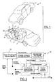
- the present invention is illustrated with respect to a pre-crash threat assessment and safety device activation system 1, particularly suited to the automotive field.
- the present invention is, however, applicable to various other uses that may require pre-crash threat assessment such as aircraft, boats, trains as will be understood by one skilled in the art.
- a pre-crash assessment system including a first target object illustrated here as a first target vehicle 2 imminently colliding with a host object illustrated here as a host vehicle 3.
- the first target object is an object, either stationary or in motion, that has a high potential for crash with the host vehicle 3.
- the high potential for crash is generally defined as an object on a collision path with and less than thirty meters (i.e. a near zone) from the host vehicle 3.
- the host object is an object in motion, mounted with at least one remote sensor.
- the pre-crash assessment system includes a high frequency remote sensor or a remote sensing system 4 coupled to the host vehicle 3.
- the sensor or sensing system 4 detects vehicle states that is to say the dynamics of the first target vehicle 2. Examples of vehicle states are position and velocity.
- the system 1 ideally includes at least one status monitoring sensor 5, such as a yaw rate sensor, a steering wheel angle measuring sensor, and a vehicle speed sensing means, coupled to the host vehicle 3.
- the status monitoring sensors 5 provide information on the present states of the host vehicle 3, which are subsequently used by host vehicle systems, as will be discussed later.
- the first safety device actuator 6 is coupled to the host vehicle 3. This actuator 6 activates the first safety device 7, here embodied as an airbag pre-arming system but which could be any other electronically controlled safety device such as a seat belt pre-tensioner.
- the second safety device actuator 8 is also coupled to the host vehicle 3.
- the second safety device actuator 8 activates a second safety device 9, here embodied as a motorized safety belt pre-tensioner but which could be any other electronically controlled safety device or system. It is important to note that numerous actuators and safety devices may be added to the system as needed by the manufacturer.
- a safety device controller 10 is also coupled to the host vehicle 3.
- the remote sensing system detects the relative position of the target vehicle, as a function of time, with respect to the X 1 Y 1 coordinate system attached at the front centre-line of the host vehicle 3.
- the host vehicle sensing system 5 detects the host vehicle dynamics in terms of the XY coordinate system, centred at the instantaneous centre of rotation (A) of the host vehicle 3.
- the safety device controller 10 From the above information, the safety device controller 10 generates a tracking signal for the target vehicle 2 in the XY coordinate system, as explained in detail later. From the tracking signals of target and host vehicles in the XY coordinate system, the controller 10 predicts the future positions of the host and target vehicles, in the XY coordinate system, at a specific future time. From this information, the controller 10 estimates the position of the nearest scattering centre on the target vehicle with respect to the host vehicle in the X 1 Y 1 coordinate system.
- Each individual safety device has a substantially unique time requirement to become fully effective, and the decision to activate a particular safety device takes this unique time requirement into consideration. For example, the activation decision time for motorized belt pre-tensioners is earlier than for pre-arming airbags due to relatively longer deployment time requirements for the motorized belt pre-tensioners.
- the controller 10 estimates the future position of the target vehicle 2, with respect to the host vehicle 3, at each of the activation times, which correspond to the safety devices under consideration.
- the controller 10 estimates whether a potential for crash between the host vehicle 3 and the first target vehicle 2 is within the first threshold criteria for the first safety device actuator 6, based on the activation time considerations of the first safety device.
- the controller 10 also estimates whether a potential for crash between the host vehicle 3 and the first target vehicle 2 is within the second threshold criteria for the second safety device actuator 8, based on the activation time considerations of the second safety device.
- the assessment is made by comparing the predicted x and y coordinates of the nearest scattering centre on the target vehicle 2 with respect to the host vehicle 3 in the X 1 Y 1 coordinate system at a device specific future time. Different tolerance values can be used for x and y co-ordinate threshold comparisons and also for individual safety device activation criteria, as will be explained later.
- the safety device controller 10 further sends control signals to the host vehicle Controller Area Network Bus (CAN) 11, which controls the first safety device actuator 6 and the second safety device actuator 8 based on threat assessment evaluations, as will be understood by one skilled in the art. The operations of the controller 10 will be discussed in detail later.
- CAN Controller Area Network Bus
- FIG. 2 a block diagram of the remote sensing based pre-crash threat assessment system 12, is illustrated.
- the current invention addresses only threat assessment aspects of the system 12 (for pre-crash sensing purposes) with radar, lidar, or vision sensor based remote sensing systems.
- the system 12 starts when operation block 13, which engages signal processing and detection algorithms, receives radar sensor data and predetermined detection thresholds.
- the radar sensor data is generated when an object impedes the radar pulse and reflects the pulse back to the radar sensor on the host vehicle.
- the detection thresholds are pre-set based on acceptable probability of detection and false alarm rates.
- operation block 13 sends the data and noise accompanying the signal, as will be understood by one skilled in the art, to operation block 14.
- the probability of detection and false alarm rates has a significant effect on items such as track initiation and track quality.
- Operation block 14 associates the data from operation block 13 and engages an obstacle tracking algorithm and then sends the track estimates of the object, which is on a potential collision course with the host vehicle, and further sends the tracking error estimate signals to operation block 16, as will be understood by one skilled in the art.
- Host vehicle dynamic data, from the host vehicle dynamic sensing systems, is also sent to the operating block 16.
- operation block 16 uses this combination of received data to estimate the future states (positions) of the host vehicle and target vehicle and sends this data to operation block 18. An evaluation is then made in operation block 18 of the potential for collision of the host vehicle and the target vehicle. Operation blocks 16 and 18 are the threat assessment components of the system 12, which will be discussed in detail later. Subsequently, operation block 18 sends actuation signals to the Controller Area Network Bus (CAN) of the host vehicle, which engages the safety devices (countermeasures), as will be understood by one skilled in the art.
- CAN Controller Area Network Bus
- This invention is especially suitable for applications which require relatively longer countermeasure deployment times, such as: motorized belt pre-tensioners, and certain countermeasures under consideration for vehicle-to-vehicle collision compatibility, such as: vehicle nose-dipping and bumper airbags.
- the current invention uses host vehicle mounted remote sensing systems, such as: radar based remote sensing systems, with wide fields of coverage, in the proximity of the host vehicle.
- the invention further uses host vehicle status monitoring sensors and remote sensors to accurately predict the future positions of both the host vehicle and the target vehicle and to assess future collision probabilities. These estimated collision probabilities are used with application specific countermeasure deployment logic to activate appropriate countermeasures, for accident damage mitigation.
- FIGS 3 and 4 illustrate an example of a pre-crash scenario 30 and a crash scenario 40 respectively.
- S 1 , S 2 , S 3 , S 4 , and S 5 are the positions of the host vehicle 36 at five consecutive times: t 1 , t 2 , t 3 , t 4 , and t 5 (t 5 is the approximate crash time) .
- T 1 , T 2 , T 3 , T 4 and T 5 are the positions of the nearest scattering centre 32 on one of the target vehicles being tracked with the remote sensing system, which is mounted on the host vehicle 36.
- R is the radial distance
- ⁇ is the angle made by the nearest scattering centre 32 on the target vehicle 34 with the Y 1 axis of the X 1 Y 1 coordinate system.
- the Y 1 -axis of a coordinate system (with origin at 0) is aligned with the front central line of the host vehicle 36 and moves with the host vehicle 36.
- the x and y coordinates of the nearest scattering centre 32 on the target vehicle 34, in the X 1 Y 1 Cartesian coordinate system moving with the host vehicle 36, are obtained by:
- the yaw rate ⁇ ⁇ update rate is slower than the remote sensing system update rate. Also, times t 1 , t 2 , t 3 , t 4 , and t 5 are measured from the latest yaw rate ( ⁇ ⁇ ) update time, which is used to calculate the latest instantaneous centre of rotation (A) and the radius of curvature (L 1 ).
- the x and y components of velocities and accelerations at time t 4 are calculated by numerical techniques.
- x and y components of velocity and acceleration are used to predict the future position of the nearest scattering centre 32 on the target vehicle in the XY coordinate system, at a future time ( ⁇ t), from time t 4 , from the following equations of motion:
- X T ⁇ t X Tt4 +Vx t4 *( ⁇ t)+0.5*Ax t4 *( ⁇ t) 2
- Y T ⁇ t Y Tt4 +V Yt4 * ( ⁇ t)+0.5*A Yt4 *( ⁇ t) 2 .
- V Xt4 , A Xt4 , V Yt4 , A Yt4 are velocity and acceleration components in X and Y directions (XY coordinate system with origin at A).
- different advanced filtering techniques such as Alpha-Beta-Gamma Filtering, Kalman Filtering, and Adaptive Kalman filtering are used to account for the noise in the sensor signals and to track and accurately predict the future position of the host and target vehicles.
- the position of the nearest scattering centre 32 with respect to the coordinate system X 1 Y 1 attached to the front of the host vehicle at a future time ( ⁇ t) from t 4 is used to assess the threat of collision.
- Device specific threshold criteria in conjunction with safety device specific activation logic are used to tailor activation of suitable countermeasures.
- the threshold criteria are given by: and .-( L S + c ) ⁇ Y ⁇ t ⁇ d where:-
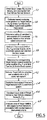
- FIG 5 in view of Figures 1, 2, 3 and 4, a block diagram of the operation of a pre-crash threat assessment and safety device activation system, in accordance with one embodiment of the present invention, is illustrated.
- operation block 52 starts in operation block 52 by obtaining the range (R i ) and the bearing ( ⁇ i ) of the first target object from the host vehicle remote sensor. Subsequently, operation block 54 activates and the nearest scattering centre on the target object (X i, Y i ), in the X 1 Y 1 coordinate system, is estimated; and the first target object track record is updated from the data sent from operation block 52.
- Operation block 56 then activates and the radius of curvature (L i ) is determined and the XY coordinate system is established based on host vehicle speed and yaw rate. Subsequently, operation block 58 activates and logic operates, as discussed in reference to Figures 3 and 4, to estimate the host vehicle position (X Sti , Y Sti ) at time t i , in the XY coordinate system. Subsequent estimations are conducted to track the host vehicle position.
- Operation block 60 then activates and the controller determines the nearest scattering centre position (X Tti , Y Tti ) of the first target vehicle at time t i , in the XY coordinate system.
- Operation block 62 logic, as discussed in reference to Figures 3 and 4, then operates to estimate the first target vehicle velocity and accelerations in the XY coordinate system. Subsequent estimations are conducted to track the first target vehicle velocities and accelerations in XY coordinate system.
- Operation block 64 then activates to predict, through the equations previously mentioned, the future state of the host and first target vehicles in the XY coordinate system.
- the prediction of the first target vehicle is transformed into the host vehicle reference coordinate system X 1 Y 1 in operation block 66.
- operation block 68 the state of the first target vehicle is evaluated with respect to the host vehicle, and requirements for countermeasure activation are assessed.
- the current embodiment combines this efficient approach for threat assessment with advanced tracking and filtering techniques, such as: Alpha-Beta-Gamma Filtering, Kalman Filtering, and Adaptive Kalman Filtering techniques, as will be understood by one skilled in the art.
- filtering techniques improve the reliability, robustness and confidence levels of the threat assessment predictions, without significantly sacrificing processing speeds, as will be understood by one skilled in the art.
- the yaw rate sensor and the vehicle speed sensors on the host vehicle are used to track the position of the host vehicle in the XY coordinate system, which is located at the instantaneous centre of rotation of the host vehicle.
- logic operates within the controller to track the position, velocity and acceleration of the host vehicle and to calculate a future position of the host vehicle in the XY coordinate system.
- logic operates to track the target object and estimate the target object velocity, acceleration and future position with respect to the XY coordinate system.
- a calculation is then made to obtain the relative position of the target vehicle with respect to the host vehicle at a future time in the host vehicle-based coordinate system (X 1 Y 1 coordinate system).
- Advantages of the current invention are that remote sensing position and bearing information of a target object in the near vicinity of the host vehicle are used and threat assessment is made through a fast, robust and reliable algorithm. Fast algorithms allow more decision making time on the part of vehicle controllers and more deployment time for safety devices and are therefore preferable.
Landscapes
- Engineering & Computer Science (AREA)
- Mechanical Engineering (AREA)
- Traffic Control Systems (AREA)
- Air Bags (AREA)
Applications Claiming Priority (2)
| Application Number | Priority Date | Filing Date | Title |
|---|---|---|---|
| US995504 | 1992-12-22 | ||
| US09/995,504 US6819991B2 (en) | 2001-11-29 | 2001-11-29 | Vehicle sensing based pre-crash threat assessment system |
Publications (2)
| Publication Number | Publication Date |
|---|---|
| EP1316481A2 true EP1316481A2 (de) | 2003-06-04 |
| EP1316481A3 EP1316481A3 (de) | 2004-11-10 |
Family
ID=25541902
Family Applications (1)
| Application Number | Title | Priority Date | Filing Date |
|---|---|---|---|
| EP02102649A Withdrawn EP1316481A3 (de) | 2001-11-29 | 2002-11-26 | Precrash Bedrohungbewertungssystem in einem Crashdetektionssytem |
Country Status (2)
| Country | Link |
|---|---|
| US (1) | US6819991B2 (de) |
| EP (1) | EP1316481A3 (de) |
Cited By (3)
| Publication number | Priority date | Publication date | Assignee | Title |
|---|---|---|---|---|
| WO2006024557A1 (de) * | 2004-08-27 | 2006-03-09 | Robert Bosch Gmbh | Verfahren und vorrichtung zur bewertung von fahrsituationen |
| EP2261090A1 (de) * | 2009-06-10 | 2010-12-15 | Robert Bosch Gmbh | Verfahren und Steuerungsvorrichtung zur Analyse einer Drehbewegung eines Fahrzeugs |
| CN108290540A (zh) * | 2015-11-04 | 2018-07-17 | 祖克斯有限公司 | 用于自主驱动车辆的内部安全系统 |
Families Citing this family (40)
| Publication number | Priority date | Publication date | Assignee | Title |
|---|---|---|---|---|
| US10361802B1 (en) | 1999-02-01 | 2019-07-23 | Blanding Hovenweep, Llc | Adaptive pattern recognition based control system and method |
| US8352400B2 (en) | 1991-12-23 | 2013-01-08 | Hoffberg Steven M | Adaptive pattern recognition based controller apparatus and method and human-factored interface therefore |
| US7359782B2 (en) * | 1994-05-23 | 2008-04-15 | Automotive Technologies International, Inc. | Vehicular impact reactive system and method |
| US8060308B2 (en) | 1997-10-22 | 2011-11-15 | Intelligent Technologies International, Inc. | Weather monitoring techniques |
| US7904187B2 (en) | 1999-02-01 | 2011-03-08 | Hoffberg Steven M | Internet appliance system and method |
| US8364136B2 (en) | 1999-02-01 | 2013-01-29 | Steven M Hoffberg | Mobile system, a method of operating mobile system and a non-transitory computer readable medium for a programmable control of a mobile system |
| DE10257842A1 (de) * | 2002-05-07 | 2003-11-27 | Bosch Gmbh Robert | Verfahren zur Bestimmung einer Unfallgefahr eines ersten Objekts mit wenigstens einem zweiten Objekt |
| GB2390461B (en) * | 2002-07-02 | 2005-06-15 | Autoliv Dev | Improvements in or relating to a triggering unit |
| JP4614050B2 (ja) * | 2004-04-27 | 2011-01-19 | アイシン精機株式会社 | 車両の乗員保護装置 |
| DE102004048191A1 (de) * | 2004-09-30 | 2006-04-06 | Robert Bosch Gmbh | Verfahren und Vorrichtung zur Erkennung einer bevorstehenden Kollision |
| US20060125615A1 (en) * | 2004-11-29 | 2006-06-15 | Song Won M | Vehicle accelerator and brake indicators |
| US20060192665A1 (en) * | 2005-02-15 | 2006-08-31 | Song Won M | System for improving the visibility of a vehicle during reduced visibility conditions |
| US20060125616A1 (en) * | 2004-11-29 | 2006-06-15 | Song Won M | Method for a changing safety signaling system |
| FR2883828B1 (fr) * | 2005-04-01 | 2007-05-25 | Conception & Dev Michelin Sa | Commande de direction de vehicule sans liaison mecanique entre volant et roues directrices |
| FR2883827B1 (fr) * | 2005-04-01 | 2007-05-18 | Conception & Dev Michelin Sa | Commande de direction de vehicule sans liaison mecanique entre volant et roues directrices |
| US7890263B2 (en) * | 2005-04-08 | 2011-02-15 | Ford Global Technologies, Llc | System and method for sensing and deployment control supervision of a safety device |
| US7138938B1 (en) * | 2005-05-06 | 2006-11-21 | Ford Global Technologies, Llc | System and method for preemptively sensing an object and selectively operating both a collision countermeasure system and a parking assistance system aboard an automotive vehicle |
| US7422293B2 (en) * | 2005-07-26 | 2008-09-09 | Ford Global Technologies, Llc | System and a method for dissipating voltage in an electrical circuit of a vehicle |
| US7260461B2 (en) * | 2005-10-31 | 2007-08-21 | Ford Global Technologies, Llc | Method for operating a pre-crash sensing system with protruding contact sensor |
| US7991551B2 (en) | 2008-11-06 | 2011-08-02 | Ford Global Technologies, Llc | System and method for determining a collision status of a nearby vehicle |
| US7991552B2 (en) | 2008-11-06 | 2011-08-02 | Ford Global Technologies, Llc | System and method for determining a side-impact collision status of a nearby vehicle |
| US8248295B2 (en) * | 2008-12-05 | 2012-08-21 | Toyota Jidosha Kabushiki Kaisha | Pre-crash safety system |
| JP2010155522A (ja) * | 2008-12-26 | 2010-07-15 | Hitachi Automotive Systems Ltd | 車両走行制御装置 |
| US9824600B1 (en) * | 2010-11-28 | 2017-11-21 | Mario Placido Portela | Electromagnetic band and photoelectric cell safety device |
| US8612099B2 (en) * | 2011-05-06 | 2013-12-17 | Tk Holdings Inc. | Occupant restraint system |
| DE102011084204A1 (de) * | 2011-10-10 | 2013-04-11 | Robert Bosch Gmbh | Verfahren zum Ansteuern von Sicherheitsaktuatorik eines Kraftfahrzeugs |
| US9226110B2 (en) * | 2012-03-31 | 2015-12-29 | Groupon, Inc. | Method and system for determining location of mobile device |
| US9266487B2 (en) * | 2014-03-17 | 2016-02-23 | Ford Global Technologies, Llc | Adaptive suppression of vehicle restraint system |
| US11167755B2 (en) | 2015-02-07 | 2021-11-09 | Hella Kgaa Hueck & Co. | Method for at least partially automatically controlling a motor vehicle |
| DE102015001638A1 (de) * | 2015-02-07 | 2016-08-11 | Hella Kgaa Hueck & Co. | Verfahren zum zumindest teilweise selbstständigen Steuern eines Kraftfahrzeuges |
| US9802568B1 (en) | 2015-09-04 | 2017-10-31 | Waymo Llc | Interlocking vehicle airbags |
| US9849852B1 (en) * | 2015-09-04 | 2017-12-26 | Waymo Llc | Intelligent deployment of safety mechanisms for autonomous vehicles |
| US9817397B1 (en) | 2015-09-04 | 2017-11-14 | Waymo Llc | Active safety mechanisms for an autonomous vehicle |
| US10118610B2 (en) * | 2016-08-31 | 2018-11-06 | Ford Global Technologies, Llc | Autonomous vehicle using path prediction |
| JP2018136240A (ja) * | 2017-02-23 | 2018-08-30 | 三菱電機株式会社 | 推定装置、推定方法、推定装置を備えた追尾装置、および推定方法を備えた追尾方法 |
| US11203318B2 (en) | 2018-06-18 | 2021-12-21 | Waymo Llc | Airbag extension system |
| US12030507B2 (en) * | 2020-06-29 | 2024-07-09 | Dr. Ing. H.C. F. Porsche Aktiengesellschaft | Method and system for predicting a trajectory of a target vehicle in an environment of a vehicle |
| US11693110B2 (en) * | 2020-11-04 | 2023-07-04 | Ford Global Technologies, Llc | Systems and methods for radar false track mitigation with camera |
| US12411211B2 (en) * | 2021-10-21 | 2025-09-09 | Rohde & Schwarz Gmbh & Co. Kg | Multistatic radar system and a method for a spatially resolved detection of an object under test |
| DE102024201055B3 (de) | 2024-02-06 | 2025-08-07 | Robert Bosch Gesellschaft mit beschränkter Haftung | Verfahren zur Kalibrierung eines ABG-Filters für die Verbesserung eines Positionssignals eines Elektromotors |
Citations (1)
| Publication number | Priority date | Publication date | Assignee | Title |
|---|---|---|---|---|
| US20020105416A1 (en) * | 2001-02-06 | 2002-08-08 | Haruhisa Kore | Occupant protection system for vehicle |
Family Cites Families (123)
| Publication number | Priority date | Publication date | Assignee | Title |
|---|---|---|---|---|
| US3514610A (en) | 1967-01-04 | 1970-05-26 | Victor J Huston | Photocell device to prevent automobile rear end collisions |
| US4257703A (en) | 1979-03-15 | 1981-03-24 | The Bendix Corporation | Collision avoidance using optical pattern growth rate |
| FR2467740A1 (fr) | 1979-10-23 | 1981-04-30 | Renault | Systeme de detection de collisions et de commande de dispositif de securite |
| US6168198B1 (en) | 1992-05-05 | 2001-01-02 | Automotive Technologies International, Inc. | Methods and arrangements for controlling an occupant restraint device in a vehicle |
| GB8304686D0 (en) | 1983-02-19 | 1983-03-23 | Sperry Ltd | Collision avoidance apparatus |
| DE3405757A1 (de) | 1983-02-26 | 1984-10-04 | Edmund 7016 Gerlingen Zottnik | Unfalldatenschreiber |
| US4673937A (en) | 1985-07-24 | 1987-06-16 | Davis John W | Automotive collision avoidance and/or air bag deployment radar |
| US4833469A (en) | 1987-08-03 | 1989-05-23 | David Constant V | Obstacle proximity detector for moving vehicles and method for use thereof |
| US4916450A (en) | 1988-05-12 | 1990-04-10 | Radar Control Systems Corporation | Radar system for headway control of a vehicle |
| KR930004579B1 (ko) | 1988-11-09 | 1993-06-01 | 미쯔비시 덴끼 가부시기가이샤 | 완속 주행장치 |
| US4992943A (en) | 1989-02-13 | 1991-02-12 | Mccracken Jack J | Apparatus for detecting and storing motor vehicle impact data |
| US5040118A (en) | 1989-11-06 | 1991-08-13 | Trw Technar Inc. | Apparatus and method employing multiple crash evaluation algorithms and evaluation expertise for actuating a restraint system in a passenger vehicle |
| US4994972A (en) | 1989-11-06 | 1991-02-19 | Trw Technar Inc. | Apparatus and method employing multiple crash evaluation algorithms for actuating a restraint system in a passenger vehicle |
| US5063603A (en) | 1989-11-06 | 1991-11-05 | David Sarnoff Research Center, Inc. | Dynamic method for recognizing objects and image processing system therefor |
| US5162794A (en) | 1989-11-21 | 1992-11-10 | Nancy Seith | Safe trailing distance warning for vehicles |
| KR940001633B1 (ko) | 1990-01-17 | 1994-02-28 | 미쯔비시 덴끼 가부시끼가이샤 | 주행 제어장치 |
| JP2905240B2 (ja) | 1990-02-07 | 1999-06-14 | アスコ株式会社 | 車両安全装置のための制御システム |
| JPH0715391B2 (ja) | 1990-05-09 | 1995-02-22 | 矢崎総業株式会社 | デジタル運行記録装置 |
| US5249157A (en) | 1990-08-22 | 1993-09-28 | Kollmorgen Corporation | Collision avoidance system |
| US5091726A (en) | 1990-08-23 | 1992-02-25 | Industrial Technology Resarch Institute | Vehicle anti-collision system |
| US5905457A (en) | 1990-10-11 | 1999-05-18 | Rashid; Charles | Vehicle radar safety apparatus |
| US5173859A (en) | 1990-11-05 | 1992-12-22 | General Motors Corporation | Automatic vehicle deceleration |
| JP2987778B2 (ja) | 1990-11-30 | 1999-12-06 | アイシン精機株式会社 | 車両速度制御装置 |
| JPH06255389A (ja) | 1991-02-26 | 1994-09-13 | Mitsubishi Electric Corp | 車両の走行制御装置 |
| US5604683A (en) | 1991-09-12 | 1997-02-18 | Lockheed Martin Corporation | Evaluating target tracking when using multiple sensors |
| JP3167752B2 (ja) | 1991-10-22 | 2001-05-21 | 富士重工業株式会社 | 車輌用距離検出装置 |
| JP2562090B2 (ja) | 1991-12-16 | 1996-12-11 | スタンレー電気株式会社 | 追突警報装置 |
| US5530651A (en) * | 1992-08-03 | 1996-06-25 | Mazda Motor Corporation | Running-safety system for an automotive vehicle |
| JPH0785280B2 (ja) | 1992-08-04 | 1995-09-13 | タカタ株式会社 | 神経回路網による衝突予測判定システム |
| JP3164439B2 (ja) | 1992-10-21 | 2001-05-08 | マツダ株式会社 | 車両用障害物検出装置 |
| JPH06150199A (ja) | 1992-11-13 | 1994-05-31 | Mitsubishi Electric Corp | 車両予防安全装置 |
| US5680097A (en) | 1992-12-10 | 1997-10-21 | Mazda Motor Corporation | Vehicle run safety apparatus |
| US5430432A (en) | 1992-12-14 | 1995-07-04 | Camhi; Elie | Automotive warning and recording system |
| US5314037A (en) | 1993-01-22 | 1994-05-24 | Shaw David C H | Automobile collision avoidance system |
| DE4407757A1 (de) | 1993-03-08 | 1994-09-15 | Mazda Motor | Vorrichtung zur Erfassung von Hindernissen für ein Fahrzeug |
| JP2946995B2 (ja) | 1993-03-31 | 1999-09-13 | 日産自動車株式会社 | 乗物用シートベルト装置 |
| US6553130B1 (en) | 1993-08-11 | 2003-04-22 | Jerome H. Lemelson | Motor vehicle warning and control system and method |
| US5983161A (en) | 1993-08-11 | 1999-11-09 | Lemelson; Jerome H. | GPS vehicle collision avoidance warning and control system and method |
| JP2799375B2 (ja) | 1993-09-30 | 1998-09-17 | 本田技研工業株式会社 | 衝突防止装置 |
| FR2713808B1 (fr) | 1993-12-14 | 1996-01-26 | Thomson Csf | Dispositif d'anticollision, notamment pour véhicules automobiles. |
| JPH07186876A (ja) | 1993-12-27 | 1995-07-25 | Asuko Kk | 車両用安全装置のための制御装置 |
| US5635922A (en) | 1993-12-27 | 1997-06-03 | Hyundai Electronics Industries Co., Ltd. | Apparatus for and method of preventing car collision utilizing laser |
| US5602760A (en) | 1994-02-02 | 1997-02-11 | Hughes Electronics | Image-based detection and tracking system and processing method employing clutter measurements and signal-to-clutter ratios |
| US5754099A (en) | 1994-03-25 | 1998-05-19 | Nippondenso Co., Ltd. | Obstacle warning system for a vehicle |
| JP3993253B2 (ja) | 1994-05-23 | 2007-10-17 | オートモーティブ・テクノロジーズ・インターナショナル,インク. | 予測センサを有する側部衝撃用エアバッグシステム |
| JP3401913B2 (ja) | 1994-05-26 | 2003-04-28 | 株式会社デンソー | 車両用障害物認識装置 |
| US5594414A (en) | 1994-08-02 | 1997-01-14 | Namngani; Abdulatif | Collision probability detection system |
| US5572596A (en) | 1994-09-02 | 1996-11-05 | David Sarnoff Research Center, Inc. | Automated, non-invasive iris recognition system and method |
| US5745870A (en) | 1994-09-14 | 1998-04-28 | Mazda Motor Corporation | Traveling-path prediction apparatus and method for vehicles |
| US5689264A (en) | 1994-10-05 | 1997-11-18 | Mazda Motor Corporation | Obstacle detecting system for vehicles |
| GB2295695B (en) | 1994-12-01 | 1999-01-20 | Lucas Ind Plc | Cruise control system for a road vehicle |
| GB9425057D0 (en) | 1994-12-13 | 1995-02-08 | Lucas Ind Plc | Apparatus and method for cruise control |
| JP3467339B2 (ja) | 1994-12-20 | 2003-11-17 | タカタ株式会社 | 車両の衝突状態制御システム |
| US6044166A (en) | 1995-01-17 | 2000-03-28 | Sarnoff Corporation | Parallel-pipelined image processing system |
| WO1996022588A1 (en) | 1995-01-17 | 1996-07-25 | David Sarnoff Research Center, Inc. | Method and apparatus for detecting object movement within an image sequence |
| KR960032262A (ko) | 1995-02-09 | 1996-09-17 | 배순훈 | 차량의 주행 안전 시스템 |
| IL112981A (en) | 1995-03-13 | 1999-03-12 | Gilon Shmuel | Collision avoidance detector |
| JP3470453B2 (ja) | 1995-04-06 | 2003-11-25 | 株式会社デンソー | 車間距離制御装置 |
| JP3390289B2 (ja) | 1995-06-16 | 2003-03-24 | 富士重工業株式会社 | 警報装置 |
| KR970005969A (ko) | 1995-07-28 | 1997-02-19 | 배순훈 | 에어백시스템의 작동기록 장치 |
| US6087928A (en) | 1995-10-31 | 2000-07-11 | Breed Automotive Technology, Inc. | Predictive impact sensing system for vehicular safety restraint systems |
| US5963272A (en) | 1995-10-31 | 1999-10-05 | Sarnoff Corporation | Method and apparatus for generating a reference image from an image sequence |
| JP2869888B2 (ja) | 1995-11-21 | 1999-03-10 | 本田技研工業株式会社 | 車両の衝突防止装置 |
| JP3257410B2 (ja) | 1995-11-24 | 2002-02-18 | トヨタ自動車株式会社 | 車載走査型レーダ装置 |
| JP3656301B2 (ja) | 1995-12-28 | 2005-06-08 | 株式会社デンソー | 車両用障害物警報装置 |
| US6049619A (en) | 1996-02-12 | 2000-04-11 | Sarnoff Corporation | Method and apparatus for detecting moving objects in two- and three-dimensional scenes |
| GB2310303B (en) | 1996-02-13 | 1999-07-28 | Autoliv Dev | Improvements in or relating to a crash detector arrangement |
| JP3726923B2 (ja) | 1996-04-10 | 2005-12-14 | 富士重工業株式会社 | 車両用運転支援装置 |
| US5646613A (en) | 1996-05-20 | 1997-07-08 | Cho; Myungeun | System for minimizing automobile collision damage |
| JP3143063B2 (ja) | 1996-06-07 | 2001-03-07 | 株式会社日立製作所 | 移動体の走行制御装置 |
| JP3708650B2 (ja) | 1996-06-11 | 2005-10-19 | トヨタ自動車株式会社 | 障害物検知装置を用いた乗員保護装置 |
| US5815093A (en) | 1996-07-26 | 1998-09-29 | Lextron Systems, Inc. | Computerized vehicle log |
| DE19637245C2 (de) | 1996-09-13 | 2000-02-24 | Bosch Gmbh Robert | Verfahren und Vorrichtung zur Regelung der Geschwindigkeit eines Fahrzeugs |
| US5948026A (en) | 1996-10-24 | 1999-09-07 | General Motors Corporation | Automotive data recorder |
| DE19647660B4 (de) | 1996-11-19 | 2005-09-01 | Daimlerchrysler Ag | Auslösevorrichtung für Insassenrückhaltesysteme in einem Fahrzeug |
| US6025796A (en) | 1996-12-09 | 2000-02-15 | Crosby, Ii; Robert G. | Radar detector for pre-impact airbag triggering |
| JP3619628B2 (ja) | 1996-12-19 | 2005-02-09 | 株式会社日立製作所 | 走行環境認識装置 |
| JP3477015B2 (ja) | 1996-12-25 | 2003-12-10 | トヨタ自動車株式会社 | 車間距離制御装置 |
| JP3866349B2 (ja) | 1996-12-27 | 2007-01-10 | 富士重工業株式会社 | 車両の衝突防止装置 |
| US6085151A (en) | 1998-01-20 | 2000-07-04 | Automotive Systems Laboratory, Inc. | Predictive collision sensing system |
| US5835007A (en) | 1997-02-10 | 1998-11-10 | Delco Electronics Corporation | Method and apparatus for crash sensing using anticipatory sensor inputs |
| US5872536A (en) | 1997-02-19 | 1999-02-16 | Hittite Microwave Corporation | Multi-sensor anticipatory object detection system |
| US5835873A (en) | 1997-02-21 | 1998-11-10 | Breed Automotive Technology, Inc. | Vehicle safety system with safety device controllers |
| GB2327821B (en) | 1997-05-17 | 1999-12-01 | Bosch Gmbh Robert | Method and device for detecting an imminent or possible collision |
| US5949918A (en) | 1997-05-21 | 1999-09-07 | Sarnoff Corporation | Method and apparatus for performing image enhancement |
| US5920345A (en) | 1997-06-02 | 1999-07-06 | Sarnoff Corporation | CMOS image sensor with improved fill factor |
| JP3645988B2 (ja) | 1997-06-30 | 2005-05-11 | 本田技研工業株式会社 | 車両の障害物検知装置 |
| EP0891903B1 (de) | 1997-07-17 | 2009-02-11 | Volkswagen Aktiengesellschaft | Automatische Notbremsfunktion |
| US6025797A (en) | 1997-07-22 | 2000-02-15 | Denso Corporation | Angular shift determining apparatus for determining angular shift of central axis of radar used in automotive obstacle detection system |
| JP3684776B2 (ja) | 1997-07-23 | 2005-08-17 | 株式会社デンソー | 車両用障害物認識装置 |
| US6002983A (en) | 1997-08-27 | 1999-12-14 | Delphi Technologies, Inc. | Angle extent estimation method for a motor vehicle object detection system |
| US5964822A (en) | 1997-08-27 | 1999-10-12 | Delco Electronics Corp. | Automatic sensor azimuth alignment |
| US5926126A (en) | 1997-09-08 | 1999-07-20 | Ford Global Technologies, Inc. | Method and system for detecting an in-path target obstacle in front of a vehicle |
| US5906393A (en) | 1997-09-16 | 1999-05-25 | Trw Inc. | Occupant restraint system and control method with variable sense, sample, and determination rates |
| US5838228A (en) | 1997-09-18 | 1998-11-17 | Clark; Dennis D. | System for preventing rear end collisions |
| DE19741631B4 (de) | 1997-09-20 | 2013-08-14 | Volkswagen Ag | Verfahren und Vorrichtung zur Vermeidung und/oder Minimierung von Konfliktsituationen im Straßenverkehr |
| US6088639A (en) | 1997-10-03 | 2000-07-11 | Delco Electronics Corporation | Method of enabling and disabling occupant restraints |
| DE59809476D1 (de) | 1997-11-03 | 2003-10-09 | Volkswagen Ag | Autonomes Fahrzeug und Verfahren zur Steuerung eines autonomen Fahrzeuges |
| JP3898323B2 (ja) | 1998-01-19 | 2007-03-28 | 本田技研工業株式会社 | 車両の統合制御装置 |
| DE19804957A1 (de) | 1998-02-07 | 1999-08-12 | Itt Mfg Enterprises Inc | Abstandsmeßverfahren mit adaptiver Verstärkung |
| JP4037506B2 (ja) | 1998-03-12 | 2008-01-23 | 富士重工業株式会社 | 車両運動制御装置 |
| JPH11305243A (ja) | 1998-04-16 | 1999-11-05 | Internatl Business Mach Corp <Ibm> | 液晶表示装置 |
| JP3926925B2 (ja) | 1998-05-27 | 2007-06-06 | 日産自動車株式会社 | 先行車追従制御装置 |
| US6259992B1 (en) | 1998-06-03 | 2001-07-10 | Honda Giken Kogyo Kabushiki Kaisha | Vehicle safety running control system |
| US6081188A (en) | 1998-06-08 | 2000-06-27 | Emergency Warning Systems, Inc. | Vehicular hazard warning system |
| JPH11353565A (ja) | 1998-06-09 | 1999-12-24 | Yazaki Corp | 車両用衝突警報方法及び装置 |
| JP3828663B2 (ja) | 1998-06-11 | 2006-10-04 | 本田技研工業株式会社 | 車両の障害物回避制御装置 |
| US5999117A (en) | 1998-06-16 | 1999-12-07 | Northrop Grumman Corporation | Method for tracking and detecting turns of maneuvering targets |
| US6186539B1 (en) | 1998-07-01 | 2001-02-13 | Trw Inc. | Method and apparatus for controlling an actuatable restraint device using crash severity indexing and crush zone sensor |
| JP3986683B2 (ja) | 1998-08-25 | 2007-10-03 | 本田技研工業株式会社 | 車両の走行安全装置 |
| US6076028A (en) | 1998-09-29 | 2000-06-13 | Veridian Engineering, Inc. | Method and apparatus for automatic vehicle event detection, characterization and reporting |
| US6026340A (en) | 1998-09-30 | 2000-02-15 | The Robert Bosch Corporation | Automotive occupant sensor system and method of operation by sensor fusion |
| US6169479B1 (en) | 1998-10-23 | 2001-01-02 | Visteon Global Technologies, Inc. | Vehicular deformation sensor system |
| US6204756B1 (en) | 1998-10-23 | 2001-03-20 | Visteon Global Technologies, Inc. | Diagnostics for vehicle deformation sensor system |
| US6219606B1 (en) | 1998-11-16 | 2001-04-17 | Delphi Technologies, Inc. | Restraint deployment control method having a delayed adaptable deployment threshold |
| US6121896A (en) | 1999-01-26 | 2000-09-19 | Rahman; Anis | Motor vehicle early warning system |
| US6223125B1 (en) | 1999-02-05 | 2001-04-24 | Brett O. Hall | Collision avoidance system |
| US6225918B1 (en) | 1999-02-19 | 2001-05-01 | Bing Kam | Automatic warning signal system for vehicles |
| JP4287532B2 (ja) | 1999-03-01 | 2009-07-01 | 矢崎総業株式会社 | 車両用後側方監視装置 |
| US6185490B1 (en) | 1999-03-15 | 2001-02-06 | Thomas W. Ferguson | Vehicle crash data recorder |
| US6177866B1 (en) | 1999-05-28 | 2001-01-23 | O'connell Patricia | Tailgating warning system |
| US6161074A (en) | 1999-12-22 | 2000-12-12 | Visteon Global Technologies, Inc. | Method and system for continued vehicle control in an adaptive speed control system at vehicle speeds below a minimum operating speed when a sensed target disappears |
| US6295495B1 (en) * | 2001-04-24 | 2001-09-25 | Ford Global Technologies, Inc. | Method for multi-directional anticipatory arming of vehicle restraints |
-
2001
- 2001-11-29 US US09/995,504 patent/US6819991B2/en not_active Expired - Lifetime
-
2002
- 2002-11-26 EP EP02102649A patent/EP1316481A3/de not_active Withdrawn
Patent Citations (1)
| Publication number | Priority date | Publication date | Assignee | Title |
|---|---|---|---|---|
| US20020105416A1 (en) * | 2001-02-06 | 2002-08-08 | Haruhisa Kore | Occupant protection system for vehicle |
Cited By (4)
| Publication number | Priority date | Publication date | Assignee | Title |
|---|---|---|---|---|
| WO2006024557A1 (de) * | 2004-08-27 | 2006-03-09 | Robert Bosch Gmbh | Verfahren und vorrichtung zur bewertung von fahrsituationen |
| US7822521B2 (en) | 2004-08-27 | 2010-10-26 | Robert Bosch Gmbh | Method and device for evaluating driving situations |
| EP2261090A1 (de) * | 2009-06-10 | 2010-12-15 | Robert Bosch Gmbh | Verfahren und Steuerungsvorrichtung zur Analyse einer Drehbewegung eines Fahrzeugs |
| CN108290540A (zh) * | 2015-11-04 | 2018-07-17 | 祖克斯有限公司 | 用于自主驱动车辆的内部安全系统 |
Also Published As
| Publication number | Publication date |
|---|---|
| EP1316481A3 (de) | 2004-11-10 |
| US6819991B2 (en) | 2004-11-16 |
| US20040111200A1 (en) | 2004-06-10 |
Similar Documents
| Publication | Publication Date | Title |
|---|---|---|
| US6819991B2 (en) | Vehicle sensing based pre-crash threat assessment system | |
| EP1316480B1 (de) | Precrash Bedrohungbewertungssystem in einem Crashdetektionssytem | |
| US6801843B2 (en) | Vehicle pre-crash sensing based conic target threat assessment system | |
| US7243013B2 (en) | Vehicle radar-based side impact assessment method | |
| US8527151B2 (en) | Side impact safety system with blind-spot detection radar data fusion | |
| US6452535B1 (en) | Method and apparatus for impact crash mitigation | |
| US6944543B2 (en) | Integrated collision prediction and safety systems control for improved vehicle safety | |
| EP2056123B1 (de) | Kollisionsvermeidungs- und Kollisionswarnsystem und -verfahren | |
| US8798885B2 (en) | Collision reducing device | |
| US6420996B1 (en) | Integrated radar and active transponder collision prediction system | |
| EP1632404B1 (de) | Vorrichtung und Verfahren zur Feststellung einer bevorstehenden Kollision | |
| EP1367411B1 (de) | System zur Kollisionserkennung und Verfahren zur Schätzung des Fehlabstandes | |
| EP1566657B1 (de) | System zur Kollisionserkennung und Verfahren zur Schätzung der Position eines Zieles | |
| US20130181860A1 (en) | Radar based multifunctional safety system | |
| US20070131468A1 (en) | Motor vehicle provided with a pre-safe system | |
| JP2003205804A (ja) | 車両用衝突被害軽減装置 | |
| EP1535807A2 (de) | Verfahren und Vorrichtung zur Auslösung von Gegenmassnahmen als Antwort auf eine festgestellte bevorstehende Fahrzeugkollision | |
| WO1998015435A1 (en) | Improvements relating to vehicle airbag deployment | |
| US6650983B1 (en) | Method for classifying an impact in a pre-crash sensing system in a vehicle having a countermeasure system | |
| EP1367410B1 (de) | System zur Kollisionserkennung und Verfahren zur Schätzung des fehlenden Abstandes mittels Kurvenannäherung | |
| US6650984B1 (en) | Method for determining a time to impact in a danger zone for a vehicle having a pre-crash sensing system | |
| US7130730B2 (en) | Sensing strategy for damage mitigation in compatability situations | |
| US20100063685A1 (en) | Motor vechicle having a preventive action protection system | |
| JP4858201B2 (ja) | 車両用衝突判断装置 | |
| JP4200131B2 (ja) | 第1の対象物の事故の危険性を少なくとも1つの第2の対象物により判定する方法 |
Legal Events
| Date | Code | Title | Description |
|---|---|---|---|
| PUAI | Public reference made under article 153(3) epc to a published international application that has entered the european phase |
Free format text: ORIGINAL CODE: 0009012 |
|
| AK | Designated contracting states |
Designated state(s): AT BE BG CH CY CZ DE DK EE ES FI FR GB GR IE IT LI LU MC NL PT SE SK TR |
|
| AX | Request for extension of the european patent |
Extension state: AL LT LV MK RO SI |
|
| PUAL | Search report despatched |
Free format text: ORIGINAL CODE: 0009013 |
|
| AK | Designated contracting states |
Kind code of ref document: A3 Designated state(s): AT BE BG CH CY CZ DE DK EE ES FI FR GB GR IE IT LI LU MC NL PT SE SK TR |
|
| AX | Request for extension of the european patent |
Extension state: AL LT LV MK RO SI |
|
| RIC1 | Information provided on ipc code assigned before grant |
Ipc: 7B 60R 21/01 B Ipc: 7G 01S 13/93 A |
|
| 17P | Request for examination filed |
Effective date: 20050408 |
|
| AKX | Designation fees paid |
Designated state(s): DE FR GB |
|
| 17Q | First examination report despatched |
Effective date: 20061017 |
|
| STAA | Information on the status of an ep patent application or granted ep patent |
Free format text: STATUS: THE APPLICATION HAS BEEN WITHDRAWN |
|
| 18W | Application withdrawn |
Effective date: 20091127 |