EP1293552A2 - Verfahren und Vorrichtung zur Beschickung von Koksöfen einer Koksofenbatterie - Google Patents
Verfahren und Vorrichtung zur Beschickung von Koksöfen einer Koksofenbatterie Download PDFInfo
- Publication number
- EP1293552A2 EP1293552A2 EP02020644A EP02020644A EP1293552A2 EP 1293552 A2 EP1293552 A2 EP 1293552A2 EP 02020644 A EP02020644 A EP 02020644A EP 02020644 A EP02020644 A EP 02020644A EP 1293552 A2 EP1293552 A2 EP 1293552A2
- Authority
- EP
- European Patent Office
- Prior art keywords
- filling
- coal
- operating unit
- fülllochrahmen
- telescope
- Prior art date
- Legal status (The legal status is an assumption and is not a legal conclusion. Google has not performed a legal analysis and makes no representation as to the accuracy of the status listed.)
- Granted
Links
Images

Classifications
-
- C—CHEMISTRY; METALLURGY
- C10—PETROLEUM, GAS OR COKE INDUSTRIES; TECHNICAL GASES CONTAINING CARBON MONOXIDE; FUELS; LUBRICANTS; PEAT
- C10B—DESTRUCTIVE DISTILLATION OF CARBONACEOUS MATERIALS FOR PRODUCTION OF GAS, COKE, TAR, OR SIMILAR MATERIALS
- C10B25/00—Doors or closures for coke ovens
- C10B25/20—Lids or closures for charging holes
- C10B25/24—Lids or closures for charging holes for ovens with horizontal chambers
-
- C—CHEMISTRY; METALLURGY
- C10—PETROLEUM, GAS OR COKE INDUSTRIES; TECHNICAL GASES CONTAINING CARBON MONOXIDE; FUELS; LUBRICANTS; PEAT
- C10B—DESTRUCTIVE DISTILLATION OF CARBONACEOUS MATERIALS FOR PRODUCTION OF GAS, COKE, TAR, OR SIMILAR MATERIALS
- C10B31/00—Charging devices
- C10B31/02—Charging devices for charging vertically
- C10B31/04—Charging devices for charging vertically coke ovens with horizontal chambers
Definitions
- the invention relates to a method for feeding Coke ovens of a coke oven battery, in which a coal filling car on the furnace roof in the longitudinal direction of the coke oven battery method and for filling the coke ovens at predetermined Positions is positioned, followed by a lid lifted from a filling hole, a surrounding the filling hole Filling hole frame cleaned and a filling telescope for filling of the coke oven is lowered onto the Gearlochrahmen.
- the Operating unit can be moved in X-direction, whereby the travel is set up so that in a first job position the filling hole cover is freely accessible to the Deckelabhebevoriques and with unchanged location of the Coal filling car in a second working position of the outlet is substantially aligned with the filling hole.
- the known measures allow the compensation of Gearloch-position deviations at most on the order of magnitude ⁇ 50 mm in the X and Y directions. Especially with older ones Coking plants can change the operational situation the Gearlochrahmen orders of magnitude up to ⁇ 150 mm in Longitudinal and transverse direction amount. To eliminate the not Tolerable postponements are expensive, operationally restrictive and carried out costly measures, around the Grefen in an acceptable tolerance restore. These measures must be taken if necessary at intervals depending on the state of the coke oven battery be repeated.
- the invention is based on the object, the method for Charging of coke ovens of a coke oven battery so to train that without operational changes to the coke oven battery a proper filling of the coke ovens too then it is ensured that the Grelochrahmen in L jossund Transverse direction (X, Y) more or less large positional deviations from a predetermined home position.
- the filling telescope, the lid lifter and the frame cleaner are combined according to the invention into an operating unit, the all occurring position deviations of Greefen in the longitudinal direction (X direction) of the coke oven battery and across to compensate (Y-direction), without the Artlochrahmen complicated and with considerable costs Need to become.
- the operational deviations of the Fill hole frames are measured and for each Articulllen preferably in the machine control of the coal filling truck saved. From time to time and as needed they will be updated.
- To fill the coke oven battery is the coal filling car on the furnace roof e.g. with the help of an automatic Positioning system at a filling hole in usual Positioned, regardless of any, operational filling hole position deviations.
- To Subject of stored for the Grelochrahmen concerned Deviation in position is the filling telescope, Deckelabheber and frame cleaner existing operating unit in X / Y direction adjusted and the real position of the concerned Grelochrahmens set. The adjustment takes place using internal and / or external distance measuring systems linear in X and Y direction or by Combination of a linear positioning movement in the longitudinal direction (X-direction) with a rotation about a vertical Axis.
- the Deckelabheber, the frame cleaner and the filling telescope in their respective working positions to be moved. Since fill hole position deviations before are compensated, the facilities are in their respective Working position always exactly above the filling hole frame. The filling telescope, the lid lifter and the frame cleaner only need one vertical movement, to get to the filling hole cover or in the Grelochrahmen.
- the Operating unit on a screw conveyor which has a Coal outlet at the bottom of the coal filling wagon with Coal is charged, the coal arranged offset Filling telescope feeds and to compensate for positional deviations the Grelochrahmen in the transverse direction around the Kohleauslass is turned.
- the lid lifter and the frame cleaner are appropriate laterally to the filling telescope on the screw conveyor attached. This will be used to position the Lid lifter, frame cleaner and filling telescope in the respective working positions around the coal outlet pivoted.
- the invention teaches that the operating unit to compensate for changes in location the Grelochrahmen on a Verstellwagen, on treads is guided on the underside of the coal filling car and guides for a transverse or rotational movement of the operating unit has, is moved.
- the invention is also a Kohle sleepllwagen to Implementation of the described method according to claim 7.
- Preferred constructive embodiments of the coal hopper are described in the dependent claims 8 to 14.
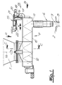
- the device shown in the figures is at the Bottom of a coal hopper arranged.
- the coal filling car has a lower coal outlet 1 and is on the furnace roof 2 in the longitudinal direction of a coke oven battery method and for filling the coke ovens at predetermined Positions positioned in the area of filling openings 3.
- a lid 4 of the filling hole 3 lifted, a Golflochrahmen surrounding the filling hole 5 cleaned and a filling telescope 6 for filling of the coke oven is lowered onto the Grelochrahmen 5.
- the screw conveyor 7 has a housing 10 with a arranged under the coal outlet 1 coal application area, a connected to the filling telescope 6 outlet 11 and a motor-driven worm shaft 12.
- the filling telescope 6, the lid lift 8 and the frame cleaner 9 are with the screw conveyor 7 to an operating unit 13 united in a horizontal plane is movably guided.
- the operation unit 13 is in the in The embodiment shown in FIGS. 1 to 5 to a vertical axis 14 rotatably on a Verstellwagen 15th arranged in the longitudinal direction (X direction) on rails 16 is guided.
- the rails 16 are at the bottom of the Coal filling carriage arranged.
- the Operating unit 13 axially movable and rotatable about the Kohleauslass 1 out and on a circular arc Lane 17 supported on the adjustment carriage 15.
- FIG. 1 If one takes away that the operating unit with a rocker 18, the rollers 19, on the adjustment carriage 15th is suspended.
- an actuator 20th On the rocker 18 is an actuator 20th arranged with a pinion, with one on the adjustment carriage 15 arranged tooth profile 21 meshes.
- the actuator 18 By operation of the actuator 18 is the operating unit 13 to the rotation axis 14 pivotable.
- the adjustment By another actuator 22, for example, as a hydraulic cylinder piston assembly is executed, the adjustment is 15 in Longitudinal direction (X-direction) movable. Actuation of the drives 20, 22, the operating unit 13 both in the longitudinal direction adjusted as well as about the vertical axis of rotation 14th be panned.
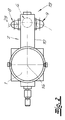
- FIG. 2 and 3 A comparative consideration of Figs. 2 and 3 extracts one, that the Deckelabheber 8 and the frame cleaner. 9 laterally connected to the housing 10 of the screw conveyor 7 are, with the working areas of these devices 8, 9 and the working area of the filling telescope 6 a common circular arc trajectory 23 to the Rotary axis 14 of the operating unit 13 are arranged. By Rotation of the operating unit 13, the lid lift 8, the filling telescope 6 and the frame cleaner 9 each in one Working position are brought above the filling hole 3.
- the device described allows a very precise Alignment of the filling telescope 6, the Deckelabhebers 8 and of the frame cleaner 9 to the filling openings 3 in the furnace roof 2 and is capable of operational fill hole positional deviations from a given basic position both in the longitudinal direction of the coke oven battery as well as in Transverse direction, ie in the X and Y direction, to compensate.
- the positional deviations can often in the order of ⁇ 100 to 150 mm in both axes be.
- the horizontal position deviations of the Grelochrahmen 5 are measured in the longitudinal and transverse directions and for each fill hole frame in a machine control on the Coal filling cars stored and updated as needed.
- the coal filling car is placed on the furnace roof 2 of the coke oven battery method and without consideration of positional deviations the filling openings 3 for filling a coke oven at a given location, that of the filling opening is assigned, positioned.
- the positioning can be, for example using an automatic positioning system with a positioning accuracy of less than 5 mm.
- This is the filling telescope 6, the lid lifter 8 and the frame cleaner 9 comprehensive Operating unit 13 in accordance with the stored X / Y values for the positional deviation of the Grelochrahmens 5 in one of the actual position of the Grelochrahmens 5 associated Position brought.
- the complete operating unit 13 is thus on the real situation set the Grelochrahmens 5.
- the Deckelabheber 8, the frame cleaner 9 and the filling telescope 6 in their respective working positions be moved above the filling hole 3. Since the relevant Pivoting movements for the Deckelabheber 8 and the Frame cleaner 9 always the same amount or tilt angle have facilities 6, 8, 9 after graduation the corresponding pivoting movement always exactly over the Grelochrahmen 5.
- the Artteleskop 6, the Deckelabheber 8 and the frame cleaner 9 therefore only need each a vertical movement to the Grelochdeckel 4 and in the Grelochrahmen 5 to get and do not need themselves Compensating devices for compensation of filling hole position deviations.
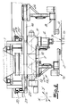
- the operating unit 13 a Verstellwagen 15 'on the on a road 23 guided on the underside of the coal filling carriage is.
- the carriageway 23 is in the steel construction of the coal filling wagon integrated and extends in the embodiment in the Y direction.
- Actuators 20 are provided by the machine control be controlled.
- the screw conveyor 7, the Deckelabheber 8 and the frame cleaner 9 are on the adjustment 15 'transverse to the direction of movement, in the embodiment So in the X direction, arranged movable.
- the adjustment carriage 15 'or the screw conveyor 7 are Actuators 20, 22 assigned whose travel on the matched maximum possible positional deviations of the Grelochrahmen 5 are.
- the lid lifter and the frame cleaner are equipped with separate traction drives 24, which also be controlled by the machine control. you The route is according to the stored X-values, which the positional shift of Grelochrahmen in the direction of the route, compensated.
Landscapes
- Chemical & Material Sciences (AREA)
- Engineering & Computer Science (AREA)
- Materials Engineering (AREA)
- Oil, Petroleum & Natural Gas (AREA)
- Organic Chemistry (AREA)
- Coke Industry (AREA)
- Charge And Discharge Circuits For Batteries Or The Like (AREA)
Abstract
Description
dass horizontale Lageabweichungen der Fülllochrahmen von einer Grundposition in Längs- und Querrichtung (X, Y) gemessen und gespeichert werden und
dass eine das Füllteleskop, einen Deckelabheber sowie einen Rahmenreiniger umfassende Betriebseinheit, die verstellbeweglich an den Kohlefüllwagen angeschlossen ist, nach Maßgabe der gespeicherten Werte in eine der tatsächlichen Lage der Fülllochrahmen zugeordnete Position gebracht wird sowie aus dieser Position der Deckelabheber, der Rahmenreiniger und das Füllteleskop in ihre jeweiligen Arbeitspositionen bewegt werden.
- Fig. 1
- eine an der Unterseite eines Kohlefüllwagen angeordnete Vorrichtung zur Beschickung von Koksöfen einer Koksofenbatterie,
- Fig. 2
- eine Draufsicht auf die in Fig. 1 dargestellte Vorrichtung aus der Blickrichtung A,
- Fig. 3
- eine stirnseitige Ansicht der in Fig. 1 dargestellten Vorrichtung aus der Blickrichtung B,
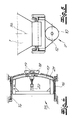
- Fig. 4
- die Draufsicht auf einen zu der Vorrichtung in Fig. 1 gehörenden Verstellwagen,
- Fig. 5
- den Querschnitt C-C aus Fig. 1, und
- Fig. 6
- eine weitere Ausgestaltung der erfindungsgemäßen Vorrichtung.
Claims (14)
- Verfahren zur Beschickung von Koksöfen einer Koksofenbatterie, bei dem ein Kohlefüllwagen auf der Ofendecke in Längsrichtung der Koksofenbatterie verfahren und zur Befüllung der Koksöfen an vorgegebenen Stellen positioniert wird, wobei anschließend ein Deckel von einem Füllloch abgehoben, ein das Füllloch umgebender Fülllochrahmen gereinigt und ein Füllteleskop zur Befüllung des Koksofens auf den Fülllochrahmen abgesenkt wird, dadurch gekennzeichnet, dass horizontale Lageabweichungen der Fülllochrahmen von einer Grundposition in Längs- und Querrichtung gemessen und gespeichert werden und
dass eine das Füllteleskop, einen Deckelabheber sowie einen Rahmenreiniger umfassende Betriebseinheit, die verstellbeweglich an den Kohlefüllwagen angeschlossen ist, nach Maßgabe der gespeicherten Werte in eine der tatsächlichen Lage der Fülllochrahmen zugeordnete Position gebracht wird sowie aus dieser Position der Deckelabheber, der Rahmenreiniger und das Füllteleskop in ihre jeweiligen Arbeitspositionen bewegt werden. - Verfahren nach Anspruch 1, dadurch gekennzeichnet, dass die Lageabweichungen für jeden Fülllochrahmen in der Maschinensteuerung des Kohlefüllwagens gespeichert und nach Bedarf aktualisiert werden.
- Verfahren nach Anspruch 1 oder 2, dadurch gekennzeichnet, dass die Betriebseinheit zum Ausgleich von Lageabweichungen der Fülllochrahmen in Querrichtung um eine vertikale Achse verschwenkt wird.
- Verfahren nach einem der Ansprüche 1 bis 3, dadurch gekennzeichnet, dass die Betriebseinheit einen Schneckenförderer aufweist, der über einen Kohleauslass an der Unterseite des Kohlefüllwagens mit Kohle beschickt wird, die Kohle dem versetzt angeordneten Füllteleskop zuführt und zum Ausgleich von Lageabweichungen der Fülllochrahmen in Querrichtung um den Kohleauslass gedreht wird.
- Verfahren nach Anspruch 4, dadurch gekennzeichnet, dass der Deckelabheber und der Rahmenreiniger seitlich zum Füllteleskop an dem Schneckenförderer befestigt sind und dass der Schneckenförderer zur Positionierung des Deckelabhebers, des Rahmenreinigers und des Füllteleskops in den jeweiligen Arbeitspositionen um den Kohleauslass verschwenkt wird.
- Verfahren nach einem der Ansprüche 1 bis 5, dadurch gekennzeichnet, dass die Betriebseinheit zum Ausgleich von Lageänderungen der Fülllochrahmen auf einem Verstellwagen, der auf Laufflächen an der Unterseite des Kohlefüllwagens geführt ist und Führungen für Quer- und Drehbewegungen der Betriebseinheit aufweist, verfahren wird.
- Kohlefüllwagen für das Verfahren nach einem der Ansprüche 1 bis 6, mit
unterseitigem Kohleauslass (1),
Schneckenförderer (7),
Füllteleskop (6),
Deckelabheber (8),
Rahmenreiniger (9) und
einer Maschinensteuerung,
wobei der Schneckenförderer (7) ein Fördergehäuse (10) mit einem unter dem Kohleauslass (1) angeordneten Kohleaufgabebereich, einen mit dem Füllteleskop (6) verbundenen Auslassstutzen (11) und eine motorisch angetriebene Schneckenwelle (12) aufweist, wobei das Füllteleskop (6), der Deckelabheber (8) und der Rahmenreiniger (9) mit dem Schneckenförderer zu einer Betriebseinheit vereinigt sind, die in einer horizontalen Ebene beweglich geführt ist, und wobei der Betriebseinheit an die Maschinensteuerung angeschlossene Stellantriebe (20, 22) für Stellbewegungen zugeordnet sind, dadurch gekennzeichnet, dass Lageabweichungen der Fülllochrahmen (5) von einer Grundposition in Längs- und Querrichtung (X, Y) in der Maschinensteuerung gespeichert sind, die durch Stellbewegungen der Stellantriebe (20, 22) kompensierbar sind. - Kohlefüllwagen nach Anspruch 7, dadurch gekennzeichnet, dass die Betriebseinheit (13) in Querrichtung (Y) linear beweglich oder um eine vertikale Achse (14) drehbeweglich auf einem Verstellwagen (15) angeordnet ist und dass der Verstellwagen (15) in Längsrichtung (X) auf Schienen (18) geführt ist, die an der Unterseite des Kohlefüllwagens angeordnet sind.
- Kohlefüllwagen nach Anspruch 8, dadurch gekennzeichnet, dass die Betriebseinheit (13) axial beweglich und drehbeweglich um den Kohleauslass (1) geführt sowie auf einer kreisbogenförmigen Bahn (17) auf dem Verstellwagen (13) abgestützt ist.
- Kohlefüllwagen nach Anspruch 8 oder 9, dadurch gekennzeichnet, dass der Stellantrieb (20) für eine Quer- oder Drehbewegung der Betriebseinheit (13) ein Ritzel aufweist, das mit einem auf dem Verstellwagen (15) angeordneten Zahnprofil (21) kämmt.
- Kohlefüllwagen nach einem der Ansprüche 7 bis 10, dadurch gekennzeichnet, dass der Deckelabheber (8) und der Rahmenreiniger (9) seitlich an das Gehäuse (10) des Schneckenförderers (7) angeschlossen sind, wobei die Arbeitsbereiche dieser Vorrichtungen (8, 9) und der Arbeitsbereich des Füllteleskops (6) auf einer gemeinsamen kreisbogenförmigen Bahnkurve (23) um die Drehachse (14) der Betriebseinheit (13) angeordnet sind.
- Kohlefüllwagen nach einem der Ansprüche 7 bis 11, dadurch gekennzeichnet, dass das Füllteleskop (6), der Deckelabheber (8) und der Rahmenreiniger (9) ohne Ausgleichseinrichtungen zur Kompensation von Füllloch-Lageabweichungen ausgebildet sind und lediglich vertikale Stellbewegungen ausführen.
- Kohlefüllwagen nach Anspruch 7, dadurch gekennzeichnet, dass die Betriebseinheit einen Verstellwagen aufweist, der auf einer Fahrbahn an der Unterseite des Kohlefüllwagens geführt ist, und dass der Schneckenförderer, der Deckelabheber und der Rahmenreiniger an dem Verstellwagen quer zur Bewegungsrichtung des Verstellwagens verfahrbar angeordnet sind.
- Kohlefüllwagen nach Anspruch 13, dadurch gekennzeichnet, dass dem Verstellwagen und dem Schneckenförderer Stellantriebe zugeordnet sind, deren Stellwege auf die Lageabweichungen der Fülllochrahmen abgestimmt sind, und dass der Deckelabheber sowie der Rahmenreiniger mit separaten Fahrantrieben ausgerüstet sind.
Applications Claiming Priority (2)
| Application Number | Priority Date | Filing Date | Title |
|---|---|---|---|
| DE10145431 | 2001-09-14 | ||
| DE10145431A DE10145431C2 (de) | 2001-09-14 | 2001-09-14 | Verfahren und Vorrichtung zur Beschickung von Koksöfen einer Koksofenbatterie |
Publications (3)
| Publication Number | Publication Date |
|---|---|
| EP1293552A2 true EP1293552A2 (de) | 2003-03-19 |
| EP1293552A3 EP1293552A3 (de) | 2003-09-10 |
| EP1293552B1 EP1293552B1 (de) | 2005-08-10 |
Family
ID=7699092
Family Applications (1)
| Application Number | Title | Priority Date | Filing Date |
|---|---|---|---|
| EP02020644A Expired - Lifetime EP1293552B1 (de) | 2001-09-14 | 2002-09-13 | Verfahren und Vorrichtung zur Beschickung von Koksöfen einer Koksofenbatterie |
Country Status (4)
| Country | Link |
|---|---|
| EP (1) | EP1293552B1 (de) |
| AT (1) | ATE301698T1 (de) |
| DE (2) | DE10145431C2 (de) |
| ES (1) | ES2247244T3 (de) |
Cited By (5)
| Publication number | Priority date | Publication date | Assignee | Title |
|---|---|---|---|---|
| DE102007044181A1 (de) | 2007-09-15 | 2009-04-02 | Uhde Gmbh | Füllteleskop zum Befüllen von Koksöfen |
| WO2009106251A1 (de) * | 2008-02-28 | 2009-09-03 | Uhde Gmbh | Verfahren und vorrichtung zur positionierung von bedieneinheiten eines kohlefüllwagens an füllöffnungen eines koksofens |
| WO2009097984A3 (de) * | 2008-02-07 | 2009-11-12 | Uhde Gmbh | Vorrichtung an einem kohlefüllwagen zum abheben von deckeln aus füllochrahmen in der ofendecke eines koksofens und reinigen der füllochrahamen |
| WO2009100815A3 (de) * | 2008-02-11 | 2009-12-03 | Uhde Gmbh | Vorrichtung zum befüllen von ofenkammern eines koksofens |
| CN103339226A (zh) * | 2011-02-11 | 2013-10-02 | 蒂森克虏伯伍德公司 | 用于对炼焦炉组的炼焦炉室装料的可调节的装料孔闭合件 |
Families Citing this family (1)
| Publication number | Priority date | Publication date | Assignee | Title |
|---|---|---|---|---|
| DE102007058473B4 (de) | 2007-12-04 | 2009-11-26 | Uhde Gmbh | Verfahren und Vorrichtung zum Verschließen eines Koksofens, der durch eine horizontal gerichtete, vorder- und hinterseitige Ofenöffnung beladen oder für die Verkokung vorbereitet wird |
Family Cites Families (6)
| Publication number | Priority date | Publication date | Assignee | Title |
|---|---|---|---|---|
| DE2545265C3 (de) * | 1975-10-09 | 1979-03-01 | Fa. Carl Still, 4350 Recklinghausen | Füllwagen für Verkokungsöfen |
| DE3316936A1 (de) * | 1983-05-09 | 1984-11-15 | Dr. C. Otto & Co Gmbh, 4630 Bochum | Einrichtung zum abheben und aufsetzen der fuellochdeckel an horizontalkammer-verkokungsoefen und zum reinigen der dichtflaechen |
| DE3822928A1 (de) * | 1987-07-17 | 1989-01-26 | Tiefenbach Gmbh | Lastmagnet |
| JPH10259381A (ja) * | 1997-03-21 | 1998-09-29 | Koubukuro Kosakusho:Kk | コークス炉の石炭装入装置 |
| EP0903393B1 (de) * | 1997-09-23 | 2001-12-05 | Thyssen Krupp EnCoke GmbH | Kohlefüllwagen zum Befüllen von Verkokungskammern einer Koksofenbatterie |
| DE19743868C2 (de) * | 1997-09-23 | 2000-01-05 | Krupp Uhde Gmbh | Kohlefüllwagen zum Befüllen von Verkokungskammern einer Koksofenbatterie |
-
2001
- 2001-09-14 DE DE10145431A patent/DE10145431C2/de not_active Expired - Fee Related
-
2002
- 2002-09-13 AT AT02020644T patent/ATE301698T1/de active
- 2002-09-13 DE DE50203866T patent/DE50203866D1/de not_active Expired - Lifetime
- 2002-09-13 ES ES02020644T patent/ES2247244T3/es not_active Expired - Lifetime
- 2002-09-13 EP EP02020644A patent/EP1293552B1/de not_active Expired - Lifetime
Cited By (28)
| Publication number | Priority date | Publication date | Assignee | Title |
|---|---|---|---|---|
| US8387770B2 (en) | 2007-09-15 | 2013-03-05 | Thyssenkrupp Uhde Gmbh | Charging telescope for charging coke ovens |
| DE102007044181B4 (de) * | 2007-09-15 | 2009-05-28 | Uhde Gmbh | Füllteleskop zum Befüllen von Koksöfen |
| DE102007044181A1 (de) | 2007-09-15 | 2009-04-02 | Uhde Gmbh | Füllteleskop zum Befüllen von Koksöfen |
| US8714899B2 (en) | 2008-02-07 | 2014-05-06 | Uhde Gmbh | Apparatus on a coal-charging larry cart for lifting a lid and cleaning a charging hole |
| WO2009097984A3 (de) * | 2008-02-07 | 2009-11-12 | Uhde Gmbh | Vorrichtung an einem kohlefüllwagen zum abheben von deckeln aus füllochrahmen in der ofendecke eines koksofens und reinigen der füllochrahamen |
| KR101529357B1 (ko) * | 2008-02-07 | 2015-06-16 | 티센크루프 인더스트리얼 솔루션스 아게 | 코크스 노의 노 커버에 있는 장입 구멍 프레임으로부터 커버판을 들어올리고 장입 구멍 프레임을 클리닝하기 위한, 석탄 장입 카트 상의 장치 |
| CN101939403A (zh) * | 2008-02-07 | 2011-01-05 | 犹德有限公司 | 在装煤车上用于从焦炉炉顶中的装料孔框架提升顶盖和用于清理装料孔框架的设备 |
| TWI472604B (zh) * | 2008-02-07 | 2015-02-11 | Thyssenkrupp Uhde Gmbh | 在煤進料車上用來將蓋板從煉焦爐之爐蓋上之進料孔框架取出及用來清潔進料孔框架之裝置 |
| CN101939403B (zh) * | 2008-02-07 | 2013-05-15 | 犹德有限公司 | 在装煤车上用于从焦炉炉顶中的装料孔框架提升顶盖和用于清理装料孔框架的设备 |
| US20110030157A1 (en) * | 2008-02-07 | 2011-02-10 | Franz-Josef Schuecker | Apparatus on a coal-charging larry cart for lifting a lid out of a charging hole in the roof of a coke oven and for cleaning the charging-hold jamb |
| JP2011511140A (ja) * | 2008-02-07 | 2011-04-07 | ウーデ・ゲゼルシヤフト・ミツト・ベシユレンクテル・ハフツング | 装炭車における、コークス炉の炉天井にある装填孔フレームから蓋を取り外すため、および装填孔フレームを洗浄するための装置 |
| CN101945977B (zh) * | 2008-02-11 | 2013-05-15 | 犹德有限公司 | 用于给炼焦炉的炉腔装料的装置 |
| WO2009100815A3 (de) * | 2008-02-11 | 2009-12-03 | Uhde Gmbh | Vorrichtung zum befüllen von ofenkammern eines koksofens |
| AU2009214413B2 (en) * | 2008-02-11 | 2012-12-20 | Uhde Gmbh | Device for filling oven chambers of a coke oven |
| CN101945977A (zh) * | 2008-02-11 | 2011-01-12 | 犹德有限公司 | 用于给炼焦炉的炉腔装料的装置 |
| RU2477743C2 (ru) * | 2008-02-11 | 2013-03-20 | Тиссенкрупп Уде Гмбх | Устройство для загрузки печных камер коксовой печи |
| CN101965390B (zh) * | 2008-02-28 | 2013-05-22 | 犹德有限公司 | 将装煤车的操作单元定位在炼焦炉装料口上的方法和设备 |
| CN101965390A (zh) * | 2008-02-28 | 2011-02-02 | 犹德有限公司 | 将装煤车的操作单元定位在炼焦炉装料口上的方法和设备 |
| JP2011513523A (ja) * | 2008-02-28 | 2011-04-28 | ウーデ・ゲゼルシヤフト・ミツト・ベシユレンクテル・ハフツング | コークス炉の装入開口に石炭装入車の操作ユニットを位置決めする方法と装置 |
| RU2484120C2 (ru) * | 2008-02-28 | 2013-06-10 | Тиссенкрупп Уде Гмбх | Способ и устройство для позиционирования блоков обслуживания углезагрузочного вагона на загрузочных отверстиях коксовой печи |
| DE102008011552B4 (de) * | 2008-02-28 | 2012-08-30 | Thyssenkrupp Uhde Gmbh | Verfahren und Vorrichtung zur Positionierung von Bedieneinheiten eines Kohlefüllwagens an Füllöffnungen eines Koksofens |
| WO2009106251A1 (de) * | 2008-02-28 | 2009-09-03 | Uhde Gmbh | Verfahren und vorrichtung zur positionierung von bedieneinheiten eines kohlefüllwagens an füllöffnungen eines koksofens |
| AU2009218757B2 (en) * | 2008-02-28 | 2015-01-15 | Uhde Gmbh | Method and device for the positioning of operating units of a coal filling cart at the filling openings of a coke oven |
| DE102008011552A1 (de) * | 2008-02-28 | 2009-09-24 | Uhde Gmbh | Verfahren und Vorrichtung zur Positionierung von Bedieneinheiten eines Kohlefüllwagens an Füllöffnungen eines Koksofens |
| KR101550948B1 (ko) | 2008-02-28 | 2015-09-07 | 티센크루프 인더스트리얼 솔루션스 아게 | 코크스 오븐의 장입 포트에 석탄 장입용 카트의 운용 장비를 위치 설정하는 방법 및 장치 |
| TWI477733B (zh) * | 2008-02-28 | 2015-03-21 | Thyssenkrupp Uhde Gmbh | 於煉焦爐進料口定位煤進料車之傳動單元之方法及裝置 |
| CN103339226A (zh) * | 2011-02-11 | 2013-10-02 | 蒂森克虏伯伍德公司 | 用于对炼焦炉组的炼焦炉室装料的可调节的装料孔闭合件 |
| CN103339226B (zh) * | 2011-02-11 | 2015-03-11 | 蒂森克虏伯伍德公司 | 用于对炼焦炉组的炼焦炉室装料的可调节的装料孔闭合件 |
Also Published As
| Publication number | Publication date |
|---|---|
| DE10145431A1 (de) | 2003-05-08 |
| ATE301698T1 (de) | 2005-08-15 |
| ES2247244T3 (es) | 2006-03-01 |
| DE50203866D1 (de) | 2005-09-15 |
| EP1293552A3 (de) | 2003-09-10 |
| EP1293552B1 (de) | 2005-08-10 |
| DE10145431C2 (de) | 2003-11-13 |
Similar Documents
| Publication | Publication Date | Title |
|---|---|---|
| EP0903393B1 (de) | Kohlefüllwagen zum Befüllen von Verkokungskammern einer Koksofenbatterie | |
| DE102008008713B4 (de) | Vorrichtung zum Befüllen von Ofenkammern eines Koksofens | |
| EP2247691B1 (de) | Verfahren und vorrichtung zur positionierung von bedieneinheiten eines kohlefüllwagens an füllöffnungen eines koksofens | |
| EP2245116B1 (de) | Vorrichtung an einem kohlefüllwagen zum abheben von deckeln aus füllochrahmen in der ofendecke eines koksofens und reinigen der füllochrahamen | |
| AT402519B (de) | Kontinuierlich verfahrbare gleisbaumaschine zum verdichten der schotterbettung eines gleises | |
| DE3313187C2 (de) | ||
| CH626415A5 (de) | ||
| EP4256133B1 (de) | Verfahren zur automatischen autonomen steuerung einer stopfmaschine | |
| AT401399B (de) | Gleisbaumaschine mit einem laser-bezugsystem | |
| DE8902668U1 (de) | Positioniervorrichtung zur maßgenauen Übergabe von Werkstücken | |
| DE1658339C3 (de) | Gleisstopf- und Richtmaschine | |
| AT405425B (de) | Gleisbaumaschine mit einem laser-bezugsystem und verfahren | |
| EP1293552B1 (de) | Verfahren und Vorrichtung zur Beschickung von Koksöfen einer Koksofenbatterie | |
| DE2313055A1 (de) | Verfahren und vorrichtung zum ausund einbau von gleisjochen | |
| DE2001498C3 (de) | Einrichtung an Gleisbearbeitungsmaschinen zur Überwachung der Korrektur der Lage eines zu bearbeitenden Gleises | |
| DE2602162C2 (de) | Bezugssystemanordnung für Gleisbaumaschinen | |
| DE3409853C2 (de) | ||
| DE1004641B (de) | Verfahren und Vorrichtung zum Anheben und Ausrichten von Gleisen | |
| DE2057119A1 (de) | Fahrbare Gleisstopf Nivellierma schine | |
| CH623624A5 (de) | ||
| EP2561968B1 (de) | Vorrichtung zum Schneiden einer Scheinfuge | |
| EP0722013A1 (de) | Verfahren und Gleisbaumaschine zur Durchführung von Gleisbauarbeiten | |
| DE102021118688A1 (de) | Selbstfahrende bodenfräsmaschine, adapterset für eine bodenfräsmaschine sowie verfahren zum inkrementellen verschieben und/oder vergrössern des hubbereiches | |
| EP1522766B1 (de) | Triebstockanordnung | |
| DE3914830C2 (de) |
Legal Events
| Date | Code | Title | Description |
|---|---|---|---|
| PUAI | Public reference made under article 153(3) epc to a published international application that has entered the european phase |
Free format text: ORIGINAL CODE: 0009012 |
|
| AK | Designated contracting states |
Kind code of ref document: A2 Designated state(s): AT BE BG CH CY CZ DE DK EE ES FI FR GB GR IE IT LI LU MC NL PT SE SK TR |
|
| AX | Request for extension of the european patent |
Extension state: AL LT LV MK RO SI |
|
| PUAL | Search report despatched |
Free format text: ORIGINAL CODE: 0009013 |
|
| AK | Designated contracting states |
Kind code of ref document: A3 Designated state(s): AT BE BG CH CY CZ DE DK EE ES FI FR GB GR IE IT LI LU MC NL PT SE SK TR |
|
| AX | Request for extension of the european patent |
Extension state: AL LT LV MK RO SI |
|
| RIC1 | Information provided on ipc code assigned before grant |
Ipc: 7C 10B 31/04 A Ipc: 7F 27D 3/06 B |
|
| 17P | Request for examination filed |
Effective date: 20030828 |
|
| AKX | Designation fees paid |
Designated state(s): AT BE BG CH CY CZ DE DK EE ES FI FR GB GR IE IT LI LU MC NL PT SE SK TR |
|
| GRAP | Despatch of communication of intention to grant a patent |
Free format text: ORIGINAL CODE: EPIDOSNIGR1 |
|
| RAP1 | Party data changed (applicant data changed or rights of an application transferred) |
Owner name: UHDE GMBH |
|
| GRAS | Grant fee paid |
Free format text: ORIGINAL CODE: EPIDOSNIGR3 |
|
| GRAA | (expected) grant |
Free format text: ORIGINAL CODE: 0009210 |
|
| AK | Designated contracting states |
Kind code of ref document: B1 Designated state(s): AT BE BG CH CY CZ DE DK EE ES FI FR GB GR IE IT LI LU MC NL PT SE SK TR |
|
| PG25 | Lapsed in a contracting state [announced via postgrant information from national office to epo] |
Ref country code: EE Free format text: LAPSE BECAUSE OF FAILURE TO SUBMIT A TRANSLATION OF THE DESCRIPTION OR TO PAY THE FEE WITHIN THE PRESCRIBED TIME-LIMIT Effective date: 20050810 |
|
| REG | Reference to a national code |
Ref country code: GB Ref legal event code: FG4D Free format text: NOT ENGLISH |
|
| REG | Reference to a national code |
Ref country code: CH Ref legal event code: EP |
|
| REG | Reference to a national code |
Ref country code: IE Ref legal event code: FG4D Free format text: LANGUAGE OF EP DOCUMENT: GERMAN |
|
| PG25 | Lapsed in a contracting state [announced via postgrant information from national office to epo] |
Ref country code: CY Free format text: LAPSE BECAUSE OF FAILURE TO SUBMIT A TRANSLATION OF THE DESCRIPTION OR TO PAY THE FEE WITHIN THE PRESCRIBED TIME-LIMIT Effective date: 20050913 |
|
| REF | Corresponds to: |
Ref document number: 50203866 Country of ref document: DE Date of ref document: 20050915 Kind code of ref document: P |
|
| PG25 | Lapsed in a contracting state [announced via postgrant information from national office to epo] |
Ref country code: MC Free format text: LAPSE BECAUSE OF NON-PAYMENT OF DUE FEES Effective date: 20050930 |
|
| REG | Reference to a national code |
Ref country code: CH Ref legal event code: NV Representative=s name: KELLER & PARTNER PATENTANWAELTE AG |
|
| GBT | Gb: translation of ep patent filed (gb section 77(6)(a)/1977) |
Effective date: 20051010 |
|
| REG | Reference to a national code |
Ref country code: SE Ref legal event code: TRGR |
|
| PG25 | Lapsed in a contracting state [announced via postgrant information from national office to epo] |
Ref country code: DK Free format text: LAPSE BECAUSE OF FAILURE TO SUBMIT A TRANSLATION OF THE DESCRIPTION OR TO PAY THE FEE WITHIN THE PRESCRIBED TIME-LIMIT Effective date: 20051110 Ref country code: BG Free format text: LAPSE BECAUSE OF FAILURE TO SUBMIT A TRANSLATION OF THE DESCRIPTION OR TO PAY THE FEE WITHIN THE PRESCRIBED TIME-LIMIT Effective date: 20051110 |
|
| REG | Reference to a national code |
Ref country code: GR Ref legal event code: EP Ref document number: 20050403387 Country of ref document: GR |
|
| REG | Reference to a national code |
Ref country code: ES Ref legal event code: FG2A Ref document number: 2247244 Country of ref document: ES Kind code of ref document: T3 |
|
| ET | Fr: translation filed | ||
| PLBE | No opposition filed within time limit |
Free format text: ORIGINAL CODE: 0009261 |
|
| STAA | Information on the status of an ep patent application or granted ep patent |
Free format text: STATUS: NO OPPOSITION FILED WITHIN TIME LIMIT |
|
| 26N | No opposition filed |
Effective date: 20060511 |
|
| REG | Reference to a national code |
Ref country code: DE Ref legal event code: R082 Ref document number: 50203866 Country of ref document: DE Representative=s name: RAINER ALBRECHT, DE |
|
| REG | Reference to a national code |
Ref country code: DE Ref legal event code: R081 Ref document number: 50203866 Country of ref document: DE Owner name: THYSSENKRUPP INDUSTRIAL SOLUTIONS AG, DE Free format text: FORMER OWNER: UHDE GMBH, 44141 DORTMUND, DE Effective date: 20120627 Ref country code: DE Ref legal event code: R082 Ref document number: 50203866 Country of ref document: DE Representative=s name: ALBRECHT, RAINER, DIPL.-ING. DR.-ING., DE Effective date: 20120627 Ref country code: DE Ref legal event code: R081 Ref document number: 50203866 Country of ref document: DE Owner name: THYSSENKRUPP UHDE GMBH, DE Free format text: FORMER OWNER: UHDE GMBH, 44141 DORTMUND, DE Effective date: 20120627 |
|
| PGFP | Annual fee paid to national office [announced via postgrant information from national office to epo] |
Ref country code: IE Payment date: 20130927 Year of fee payment: 12 Ref country code: CH Payment date: 20130919 Year of fee payment: 12 Ref country code: SE Payment date: 20130919 Year of fee payment: 12 |
|
| PGFP | Annual fee paid to national office [announced via postgrant information from national office to epo] |
Ref country code: TR Payment date: 20130826 Year of fee payment: 12 |
|
| PGFP | Annual fee paid to national office [announced via postgrant information from national office to epo] |
Ref country code: LU Payment date: 20131002 Year of fee payment: 12 |
|
| PGFP | Annual fee paid to national office [announced via postgrant information from national office to epo] |
Ref country code: FI Payment date: 20140911 Year of fee payment: 13 Ref country code: GR Payment date: 20140919 Year of fee payment: 13 |
|
| PGFP | Annual fee paid to national office [announced via postgrant information from national office to epo] |
Ref country code: SK Payment date: 20140910 Year of fee payment: 13 |
|
| PGFP | Annual fee paid to national office [announced via postgrant information from national office to epo] |
Ref country code: PT Payment date: 20140313 Year of fee payment: 13 |
|
| PG25 | Lapsed in a contracting state [announced via postgrant information from national office to epo] |
Ref country code: LU Free format text: LAPSE BECAUSE OF NON-PAYMENT OF DUE FEES Effective date: 20140913 |
|
| REG | Reference to a national code |
Ref country code: CH Ref legal event code: PL |
|
| REG | Reference to a national code |
Ref country code: SE Ref legal event code: EUG |
|
| PG25 | Lapsed in a contracting state [announced via postgrant information from national office to epo] |
Ref country code: SE Free format text: LAPSE BECAUSE OF NON-PAYMENT OF DUE FEES Effective date: 20140914 |
|
| REG | Reference to a national code |
Ref country code: IE Ref legal event code: MM4A |
|
| PG25 | Lapsed in a contracting state [announced via postgrant information from national office to epo] |
Ref country code: LI Free format text: LAPSE BECAUSE OF NON-PAYMENT OF DUE FEES Effective date: 20140930 Ref country code: CH Free format text: LAPSE BECAUSE OF NON-PAYMENT OF DUE FEES Effective date: 20140930 |
|
| PG25 | Lapsed in a contracting state [announced via postgrant information from national office to epo] |
Ref country code: IE Free format text: LAPSE BECAUSE OF NON-PAYMENT OF DUE FEES Effective date: 20140913 |
|
| PGFP | Annual fee paid to national office [announced via postgrant information from national office to epo] |
Ref country code: CZ Payment date: 20150911 Year of fee payment: 14 |
|
| REG | Reference to a national code |
Ref country code: DE Ref legal event code: R082 Ref document number: 50203866 Country of ref document: DE Representative=s name: ALBRECHT, RAINER, DIPL.-ING. DR.-ING., DE Ref country code: DE Ref legal event code: R081 Ref document number: 50203866 Country of ref document: DE Owner name: THYSSENKRUPP INDUSTRIAL SOLUTIONS AG, DE Free format text: FORMER OWNER: THYSSENKRUPP UHDE GMBH, 44141 DORTMUND, DE |
|
| REG | Reference to a national code |
Ref country code: PT Ref legal event code: MM4A Free format text: LAPSE DUE TO NON-PAYMENT OF FEES Effective date: 20160314 |
|
| PG25 | Lapsed in a contracting state [announced via postgrant information from national office to epo] |
Ref country code: PT Free format text: LAPSE BECAUSE OF NON-PAYMENT OF DUE FEES Effective date: 20160314 Ref country code: FI Free format text: LAPSE BECAUSE OF NON-PAYMENT OF DUE FEES Effective date: 20150913 |
|
| REG | Reference to a national code |
Ref country code: SK Ref legal event code: MM4A Ref document number: E 257 Country of ref document: SK Effective date: 20150913 |
|
| REG | Reference to a national code |
Ref country code: GR Ref legal event code: ML Ref document number: 20050403387 Country of ref document: GR Effective date: 20160405 |
|
| PG25 | Lapsed in a contracting state [announced via postgrant information from national office to epo] |
Ref country code: GR Free format text: LAPSE BECAUSE OF NON-PAYMENT OF DUE FEES Effective date: 20160405 |
|
| PG25 | Lapsed in a contracting state [announced via postgrant information from national office to epo] |
Ref country code: SK Free format text: LAPSE BECAUSE OF NON-PAYMENT OF DUE FEES Effective date: 20150913 |
|
| REG | Reference to a national code |
Ref country code: FR Ref legal event code: PLFP Year of fee payment: 15 |
|
| PG25 | Lapsed in a contracting state [announced via postgrant information from national office to epo] |
Ref country code: CZ Free format text: LAPSE BECAUSE OF NON-PAYMENT OF DUE FEES Effective date: 20160913 |
|
| PG25 | Lapsed in a contracting state [announced via postgrant information from national office to epo] |
Ref country code: TR Free format text: LAPSE BECAUSE OF NON-PAYMENT OF DUE FEES Effective date: 20150913 |
|
| REG | Reference to a national code |
Ref country code: FR Ref legal event code: PLFP Year of fee payment: 16 |
|
| PGFP | Annual fee paid to national office [announced via postgrant information from national office to epo] |
Ref country code: FR Payment date: 20170928 Year of fee payment: 16 Ref country code: DE Payment date: 20170928 Year of fee payment: 16 Ref country code: IT Payment date: 20170926 Year of fee payment: 16 Ref country code: GB Payment date: 20170921 Year of fee payment: 16 |
|
| PGFP | Annual fee paid to national office [announced via postgrant information from national office to epo] |
Ref country code: BE Payment date: 20170921 Year of fee payment: 16 Ref country code: NL Payment date: 20170921 Year of fee payment: 16 Ref country code: AT Payment date: 20170922 Year of fee payment: 16 |
|
| PGFP | Annual fee paid to national office [announced via postgrant information from national office to epo] |
Ref country code: ES Payment date: 20171025 Year of fee payment: 16 |
|
| REG | Reference to a national code |
Ref country code: DE Ref legal event code: R119 Ref document number: 50203866 Country of ref document: DE |
|
| REG | Reference to a national code |
Ref country code: NL Ref legal event code: MM Effective date: 20181001 |
|
| REG | Reference to a national code |
Ref country code: AT Ref legal event code: MM01 Ref document number: 301698 Country of ref document: AT Kind code of ref document: T Effective date: 20180913 |
|
| GBPC | Gb: european patent ceased through non-payment of renewal fee |
Effective date: 20180913 |
|
| REG | Reference to a national code |
Ref country code: BE Ref legal event code: MM Effective date: 20180930 |
|
| PG25 | Lapsed in a contracting state [announced via postgrant information from national office to epo] |
Ref country code: NL Free format text: LAPSE BECAUSE OF NON-PAYMENT OF DUE FEES Effective date: 20181001 |
|
| PG25 | Lapsed in a contracting state [announced via postgrant information from national office to epo] |
Ref country code: DE Free format text: LAPSE BECAUSE OF NON-PAYMENT OF DUE FEES Effective date: 20190402 Ref country code: IT Free format text: LAPSE BECAUSE OF NON-PAYMENT OF DUE FEES Effective date: 20180913 |
|
| PG25 | Lapsed in a contracting state [announced via postgrant information from national office to epo] |
Ref country code: BE Free format text: LAPSE BECAUSE OF NON-PAYMENT OF DUE FEES Effective date: 20180930 Ref country code: FR Free format text: LAPSE BECAUSE OF NON-PAYMENT OF DUE FEES Effective date: 20180930 |
|
| PG25 | Lapsed in a contracting state [announced via postgrant information from national office to epo] |
Ref country code: GB Free format text: LAPSE BECAUSE OF NON-PAYMENT OF DUE FEES Effective date: 20180913 Ref country code: AT Free format text: LAPSE BECAUSE OF NON-PAYMENT OF DUE FEES Effective date: 20180913 |
|
| REG | Reference to a national code |
Ref country code: ES Ref legal event code: FD2A Effective date: 20191031 |
|
| PG25 | Lapsed in a contracting state [announced via postgrant information from national office to epo] |
Ref country code: ES Free format text: LAPSE BECAUSE OF NON-PAYMENT OF DUE FEES Effective date: 20180914 |