EP0903393B1 - Kohlefüllwagen zum Befüllen von Verkokungskammern einer Koksofenbatterie - Google Patents
Kohlefüllwagen zum Befüllen von Verkokungskammern einer Koksofenbatterie Download PDFInfo
- Publication number
- EP0903393B1 EP0903393B1 EP98115886A EP98115886A EP0903393B1 EP 0903393 B1 EP0903393 B1 EP 0903393B1 EP 98115886 A EP98115886 A EP 98115886A EP 98115886 A EP98115886 A EP 98115886A EP 0903393 B1 EP0903393 B1 EP 0903393B1
- Authority
- EP
- European Patent Office
- Prior art keywords
- screw conveyor
- coal
- casing
- charging car
- charging
- Prior art date
- Legal status (The legal status is an assumption and is not a legal conclusion. Google has not performed a legal analysis and makes no representation as to the accuracy of the status listed.)
- Expired - Lifetime
Links
- 239000000571 coke Substances 0.000 title claims description 13
- 239000003245 coal Substances 0.000 claims description 56
- 229910000831 Steel Inorganic materials 0.000 claims description 8
- 239000010959 steel Substances 0.000 claims description 8
- 238000004140 cleaning Methods 0.000 claims description 7
- 238000004939 coking Methods 0.000 description 13
- 230000008878 coupling Effects 0.000 description 4
- 238000010168 coupling process Methods 0.000 description 4
- 238000005859 coupling reaction Methods 0.000 description 4
- 238000009434 installation Methods 0.000 description 3
- 230000000052 comparative effect Effects 0.000 description 2
- 238000010276 construction Methods 0.000 description 2
- 238000005429 filling process Methods 0.000 description 2
- 238000000034 method Methods 0.000 description 2
- 238000001514 detection method Methods 0.000 description 1
- 230000032258 transport Effects 0.000 description 1
Images


Classifications
-
- C—CHEMISTRY; METALLURGY
- C10—PETROLEUM, GAS OR COKE INDUSTRIES; TECHNICAL GASES CONTAINING CARBON MONOXIDE; FUELS; LUBRICANTS; PEAT
- C10B—DESTRUCTIVE DISTILLATION OF CARBONACEOUS MATERIALS FOR PRODUCTION OF GAS, COKE, TAR, OR SIMILAR MATERIALS
- C10B25/00—Doors or closures for coke ovens
- C10B25/20—Lids or closures for charging holes
- C10B25/24—Lids or closures for charging holes for ovens with horizontal chambers
-
- C—CHEMISTRY; METALLURGY
- C10—PETROLEUM, GAS OR COKE INDUSTRIES; TECHNICAL GASES CONTAINING CARBON MONOXIDE; FUELS; LUBRICANTS; PEAT
- C10B—DESTRUCTIVE DISTILLATION OF CARBONACEOUS MATERIALS FOR PRODUCTION OF GAS, COKE, TAR, OR SIMILAR MATERIALS
- C10B31/00—Charging devices
- C10B31/02—Charging devices for charging vertically
- C10B31/04—Charging devices for charging vertically coke ovens with horizontal chambers
-
- F—MECHANICAL ENGINEERING; LIGHTING; HEATING; WEAPONS; BLASTING
- F27—FURNACES; KILNS; OVENS; RETORTS
- F27D—DETAILS OR ACCESSORIES OF FURNACES, KILNS, OVENS OR RETORTS, IN SO FAR AS THEY ARE OF KINDS OCCURRING IN MORE THAN ONE KIND OF FURNACE
- F27D3/00—Charging; Discharging; Manipulation of charge
- F27D3/06—Charging or discharging machines on travelling carriages
-
- F—MECHANICAL ENGINEERING; LIGHTING; HEATING; WEAPONS; BLASTING
- F27—FURNACES; KILNS; OVENS; RETORTS
- F27D—DETAILS OR ACCESSORIES OF FURNACES, KILNS, OVENS OR RETORTS, IN SO FAR AS THEY ARE OF KINDS OCCURRING IN MORE THAN ONE KIND OF FURNACE
- F27D21/00—Arrangement of monitoring devices; Arrangement of safety devices
- F27D21/02—Observation or illuminating devices
- F27D2021/023—Closable inserting openings, e.g. for the introduction of lances, sensors or burners
-
- F—MECHANICAL ENGINEERING; LIGHTING; HEATING; WEAPONS; BLASTING
- F27—FURNACES; KILNS; OVENS; RETORTS
- F27D—DETAILS OR ACCESSORIES OF FURNACES, KILNS, OVENS OR RETORTS, IN SO FAR AS THEY ARE OF KINDS OCCURRING IN MORE THAN ONE KIND OF FURNACE
- F27D3/00—Charging; Discharging; Manipulation of charge
- F27D3/08—Screw feeders; Screw dischargers
Definitions
- the coal filling truck is guided on the ceiling of the Coking chambers of a coke oven battery can be moved. He picks up coal from a coal tower and transports it them to the coking chambers into which they go through Filling holes is filled.
- Modern coal filling trucks show a forced feed system with a horizontal Screw conveyor below the floor outlet. Further they are with an automatic lid lifting device for opening and closing fill hole lids as well as with a telescopic tube, which the outlet of the Screw conveyor connects to the open filling hole, to avoid disturbing emissions during the filling process equipped.
- the facilities described require a large installation height on the underside of the coal filling car. The local conditions of existing coking plants allow the use of modern coal filling trucks with the described facilities often too.
- the invention has for its object a coal filling truck of the structure described at the beginning, the low installation height for the screw conveyor and distinguishes the lid lifting device.
- the task is described in the beginning Coal filling truck solved according to the invention in that the Housing of the screw conveyor at the bottom of the Coal filling truck arranged horizontally movable as well by means of an actuator with the location of the Charging car between a starting position, in which the outlet port is offset to the side of the fill hole is positioned, and a filling position in which the Outlet port is essentially aligned with the fill hole, is movable, the housing of the screw conveyor a Has top cover plate, which in the Starting position of the screw conveyor the bottom outlet of the Coal filling car closes so far that no coal on the coking chamber ceiling can leak.
- the Screw conveyor is in the direction of travel of the coal filling car aligned, the adjusting movement of the screw conveyor in the form of an axial movement in the longitudinal direction of the Screw conveyor takes place.
- the travel of the screw conveyor housing is set up so that in a first Working position (starting position) of the fill hole cover is free is accessible for the lid lifting device and at unchanged location of the coal filling truck in a second Working position (filling position) of the outlet nozzle in essentially aligned with the fill hole.
- the invention Arrangement allows the outlet port to be as deep arrange that through the telescopic tube during the Filling process can only be bridged a small distance got to.
- the telescopic tube is therefore very short executable. Additional units for operating the Telescopic tube are accordingly also as compact Executable units.
- the cover plate of the screw conveyor fulfills the function of a slide valve which Bottom outlet of the coal filling car closes and the Floor outlet only releases when filling a coking chamber takes place and the screw conveyor is in the corresponding filling position.
- a shut-off device e.g. in the form of a gate valve, arranged by a device attached to the screw conveyor can be actuated.
- a device attached to the screw conveyor can be actuated.
- At the periphery of the outlet nozzle is also a Actuator arranged by means of which Telescopic tube can be moved up and down automatically can.
- the housing of the screw conveyor is expedient Guided rails that run on both sides of the screw conveyor Actuator arranged by means of which Telescopic tube can be moved up and down automatically can.
- the lid lifting device has conventional gripping and lifting devices on. A facility is also required around a picked-up lid from the filling area to move out.
- the lid lifting device can be used for this Purpose to be equipped with a separate drive that a translational movement or a horizontal one Pivots.
- the invention is the lid lifting device on the steel substructure of the filling truck Guided rails, the rails are parallel extend to the guide rails of the screw conveyor and travel movements of the screw conveyor along the guide rails and the lid lifting device along the Running rails are rigidly coupled. It is understood that the rigid coupling on the side, through the rail guides conditional relative movements between the screw conveyor and the cover lifting device during the movement allows.
- a coupling rod is expediently provided with Spherical bearings and pivot pins used.
- the driving movement of the screw conveyor relative to the bottom outlet is at this embodiment of the invention also used to Filling hole cover, which is taken up by the cover lifting device has been moved out of the work area of the fill hole and after the filling is finished again towards the filling hole to move back.
- a hydraulic or electromechanical control device arranged on a on the housing of the Auger mounted carrier works, and is the Lid lifting device also by means of a coupling rod connected to the carrier.
- the lid lifting device is not moving of the screw conveyor, but independent from the horizontal adjustment movement of the screw conveyor housing horizontally movable.
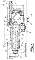
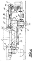
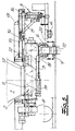
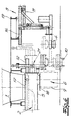
- 1 to 5 show sections of a longitudinal section through the lower part of a coal filling truck, which is in a Coke plant track-guided on the coke oven ceiling of one Coke oven battery is moved.
- the coal filling truck takes Coal from a coal tower and transported to the coking chambers of the coke oven battery.
- 6 is also in longitudinal section a further embodiment of the invention Coal filling car shown.
- the coal filling truck shown in the figures has one funnel-shaped bottom outlet 1, a horizontal Screw conveyor 2 below the floor outlet 1 and a lid lifting device 3 for opening and closing of Greochdeckeln 4 of the coking chambers.
- To the basics Construction of the screw conveyor 2 include one of housing 5 which can be loaded at the top with an outlet connection on the underside 6, at least one rotatably mounted in the housing 5 Screw conveyor 7 and a flange-mounted on the housing 5 Screw conveyor drive 8.
- a Telescopic tube 9 connected, which the outlet 6th connects to an open fill hole 10.
- the housing 5 of the screw conveyor 2 is on the underside of the coal filling car arranged horizontally movable and by means of an actuator 11 with unchanged Location of the coal filling truck between a starting position, in which the outlet port laterally to the fill hole is positioned offset, and a filling position, in which of the outlet nozzle 6 essentially with the filling hole 10 aligned, movable. 1 to 3 show the starting position, 4 and 5, the filling position of the Screw conveyor 2.
- the housing 5 of the screw conveyor 2 is guided on rails 12, which are on both sides of the housing 5 arranged on the steel substructure 13 of the coal filling car are.
- the cover lifting device 3 is on running rails 14 performed, which is also on the steel substructure 13 of the coal filling car are arranged.
- the running tracks 14 extend parallel to the guide rails 12 of the screw conveyor 2. Furthermore, one removes a comparative examination of the figures that the driving movements of the screw conveyor 2 along the guide rails 12 and the lid lifting device 3 along the Running rails are rigidly coupled.
- a hydraulic or electromechanical Setting device 11 is provided, which also on the steel substructure 13 of the coal filling car is arranged. She works on in the embodiment one attached to the housing 5 of the screw conveyor 2 Carrier 15. The cover lifting device is also on these connected by means of a coupling rod.
- the housing 5 of the screw conveyor 2 has an upper side Cover plate 17, which in the starting position of the screw conveyor 2 partially or the bottom outlet completely closed. The order is made that in the starting position no coal on the ceiling of the Coking chambers can leak.
- shut-off device e.g. in the form of a gate valve 18, arranged, by a device attached to the screw conveyor 19 can be actuated.
- the telescopic tube 9 is by means of the actuator 20 can be moved up and down automatically is.
- a vertically adjustable device 21 for cleaning the fill hole cover and fill hole frame connected is assigned to the outlet 6 end of the Screw conveyor housing 5 .
- the device 21 is together with the housing 5 between its starting position and its Filling position can be moved horizontally and is in the starting position settable on the frame of the filling hole 10.
- the Lid lifting device 3 is independent of the horizontal Adjustment movement of the screw conveyor housing 5 horizontally movable.
- the various functional positions of the device 21 are shown, partly in dashed lines, in FIG. 6.
- the Housing 5 of the screw conveyor 2 takes its starting position on.
- the Greochdeckel 4 is from the lid lifting device 3 has been added and is in one Position laterally offset from the fill hole.
- the lid lifting device 3 moves into the position shown in dashed lines and lowers the Filling hole cover 4 in the cleaning device 21.
- the cover lifting device moves 3 and the cleaning device 21 in the positions represented by solid lines. Subsequently can the screw conveyor 2 in its filling position moves and can the processes already described for coal filling.
Landscapes
- Engineering & Computer Science (AREA)
- Chemical & Material Sciences (AREA)
- Mechanical Engineering (AREA)
- General Engineering & Computer Science (AREA)
- Materials Engineering (AREA)
- Oil, Petroleum & Natural Gas (AREA)
- Organic Chemistry (AREA)
- Coke Industry (AREA)
Description
Claims (7)
- Kohlefüllwagen zum Befüllen von Verkokungskammern einer Koksofenbatterie, mitwobei der Schneckenförderer (2) ein von oben beschickbares Gehäuse (5) mit einem unterseitigen Auslaßstutzen (6), zumindest eine im Gehäuse (5) drehbar gelagerte Förderschnecke (7) sowie einen an das Gehäuse (5) angeflanschten Förderschneckenantrieb (8) aufweist und wobei an den Auslaßstutzen (6) ein Teleskoprohr (9) angeschlossen ist, welches den Auslaßstutzen (6) mit einem geöffneten Fülloch (10) verschließt, dadurch gekennzeichnet, daß das Gehäuse des Schneckenförderers (2) an der Unterseite des Kohlefüllwagens horizontal beweglich angeordnet sowie mittels eines Stellantriebs (11) bei unverändertem Standort des Kohlefüllwagens zwischen einer Ausgangsstellung, in welcher der Auslaßstutzen (6) seitlich zum Fülloch (10) versetzt positioniert ist, und einer Füllstellung, in welcher der Auslaßstutzen (6) im wesentlichen mit dem Fülloch (10) fluchtet, bewegbar ist, wobei das Gehäuse (5) des Schneckenförderers (7) eine oberseitige Abdeckplatte (17) aufweist, die in der Ausgangsstellung des Schneckenförderers (7) den Bodenauslaß (1) des Kohlefüllwagens so weit verschließt, daß keine Kohle auf die Decke der Verkokungskammern auslaufen kann.einem trichterförmigen Bodenauslaß (1),einem horizontalen Schneckenförderer (2) unterhalb des Bodenauslasses (1) undeiner Deckelabhebevorrichtung (3) zum Öffnen und Verschließen von Füllochdeckeln (4) der Koksofenkammern,
- Kohlefüllwagen nach Anspruch 1, dadurch gekennzeichnet, daß im Auslaßstutzen (6) des Schneckenförderers (2) ein Absperrorgan (18) angeordnet ist, das durch eine am Schneckenförderer (2) befestigte Vorrichtung (19) betätigbar ist.
- Kohlefüllwagen nach Anspruch 1 oder 2, dadurch gekennzeichnet, daß das Teleskoprohr (9) mittels einer am Umfang des Auslaßstutzens (6) des Schneckenförderers (2) angeordneten Betätigungsvorrichtung (20) selbsttätig auf-und abwärts bewegbar ist.
- Kohlefüllwagen nach einem der Ansprüche 1 bis 3, dadurch gekennzeichnet, daß das Gehäuse (5) des Schneckenförderers (2) auf Schienen (12) geführt ist, die beiderseits des Gehäuses (5) an der Stahlunterkonstruktion (13) des Kohlefüllwagens angeordnet sind.
- Kohlefüllwagen nach einem der Ansprüche 1 bis 4, dadurch gekennzeichnet, daß die Deckelabhebevorrichtung (3) auf an der Stahlunterkonstruktion (13) des Kohlefüllwagens angeordneten Laufschienen (14) geführt ist, wobei die Laufschienen (14) sich parallel zu den Führungsschienen (12) des Schneckenförderers (2) erstrecken und die Fahrbewegungen des Schneckenförderers (2) entlang den Führungs schienen (12) sowie der Deckelabhebevorrichtung (3) entlang der Laufschiene (14) starr gekoppelt sind.
- Kohlefüllwagen nach Anspruch 5, dadurch gekennzeichnet, daß an der Stahlunterkonstruktion (13) des Kohlefüllwagens eine hydraulische oder elektromechanische Stelleinrichtung angeordnet ist, die auf einem an dem Gehäuse des Schneckenförderers (2) befestigten Träger (15) arbeitet, und daß die Deckelabhebevorrichtung (3) mittels einer Kupplungsstange (16) ebenfalls mit dem Träger (15) verbunden ist.
- Kohlefüllwagen nach einem der Ansprüche 1 bis 4, dadurch gekennzeichnet, daß an das dem Auslaßstutzen (6) zugeordnete Ende des Schneckenförderergehäuses (5) eine vertikal verstellbare Einrichtung (21) zum Reinigen von Füllochdeckel und Füllochrahmen angeschlossen ist, die zusammen mit dem Gehäuse (5) zwischen dessen Ausgangsstellung und dessen Füllstellung horizontal verfahrbar ist und in der Ausgangsstellung auf den Rahmen des Fülloches (10) absetzbar ist.
Applications Claiming Priority (4)
| Application Number | Priority Date | Filing Date | Title |
|---|---|---|---|
| DE19741875 | 1997-09-23 | ||
| DE19741875 | 1997-09-23 | ||
| DE19743868A DE19743868C2 (de) | 1997-09-23 | 1997-10-04 | Kohlefüllwagen zum Befüllen von Verkokungskammern einer Koksofenbatterie |
| DE19743868 | 1997-10-04 |
Publications (3)
| Publication Number | Publication Date |
|---|---|
| EP0903393A2 EP0903393A2 (de) | 1999-03-24 |
| EP0903393A3 EP0903393A3 (de) | 1999-08-18 |
| EP0903393B1 true EP0903393B1 (de) | 2001-12-05 |
Family
ID=26040221
Family Applications (1)
| Application Number | Title | Priority Date | Filing Date |
|---|---|---|---|
| EP98115886A Expired - Lifetime EP0903393B1 (de) | 1997-09-23 | 1998-08-22 | Kohlefüllwagen zum Befüllen von Verkokungskammern einer Koksofenbatterie |
Country Status (5)
| Country | Link |
|---|---|
| US (2) | US6099229A (de) |
| EP (1) | EP0903393B1 (de) |
| BR (1) | BR9803970B1 (de) |
| CA (1) | CA2245380C (de) |
| PT (1) | PT903393E (de) |
Cited By (1)
| Publication number | Priority date | Publication date | Assignee | Title |
|---|---|---|---|---|
| AU2009211901B2 (en) * | 2008-02-07 | 2013-01-10 | Uhde Gmbh | Device on a coal charging car for lifting covers from filling hole frames in the furnace roof of a coke furnace and for cleaning the filling hole frames |
Families Citing this family (65)
| Publication number | Priority date | Publication date | Assignee | Title |
|---|---|---|---|---|
| US6290494B1 (en) * | 2000-10-05 | 2001-09-18 | Sun Coke Company | Method and apparatus for coal coking |
| DE10145431C2 (de) * | 2001-09-14 | 2003-11-13 | Thyssen Krupp Encoke Gmbh | Verfahren und Vorrichtung zur Beschickung von Koksöfen einer Koksofenbatterie |
| US7303597B2 (en) * | 2002-10-15 | 2007-12-04 | Pratt & Whitney Rocketdyne, Inc. | Method and apparatus for continuously feeding and pressurizing a solid material into a high pressure system |
| US7360639B2 (en) * | 2004-06-16 | 2008-04-22 | Pratt & Whitney Rocketdyne, Inc. | Hot rotary screw pump |
| US7547419B2 (en) * | 2004-06-16 | 2009-06-16 | United Technologies Corporation | Two phase injector for fluidized bed reactor |
| US7525202B2 (en) * | 2004-08-31 | 2009-04-28 | Microsoft Corporation | Quantum computational systems |
| US7402188B2 (en) * | 2004-08-31 | 2008-07-22 | Pratt & Whitney Rocketdyne, Inc. | Method and apparatus for coal gasifier |
| US7547423B2 (en) * | 2005-03-16 | 2009-06-16 | Pratt & Whitney Rocketdyne | Compact high efficiency gasifier |
| US8196848B2 (en) | 2005-04-29 | 2012-06-12 | Pratt & Whitney Rocketdyne, Inc. | Gasifier injector |
| US7717046B2 (en) * | 2005-04-29 | 2010-05-18 | Pratt & Whitney Rocketdyne, Inc. | High pressure dry coal slurry extrusion pump |
| UA90089C2 (ru) * | 2006-02-08 | 2010-04-12 | Григорий БЕРЕЗИН | Способ производства кокса из неспекающихся марок угля и устройство для его осуществления |
| DE102008008713B4 (de) * | 2008-02-11 | 2013-04-25 | Thyssenkrupp Uhde Gmbh | Vorrichtung zum Befüllen von Ofenkammern eines Koksofens |
| DE102008011552B4 (de) * | 2008-02-28 | 2012-08-30 | Thyssenkrupp Uhde Gmbh | Verfahren und Vorrichtung zur Positionierung von Bedieneinheiten eines Kohlefüllwagens an Füllöffnungen eines Koksofens |
| KR100948932B1 (ko) | 2008-10-27 | 2010-03-23 | 주식회사 포스코 | 원료탄 입조장치 |
| US7998316B2 (en) | 2009-03-17 | 2011-08-16 | Suncoke Technology And Development Corp. | Flat push coke wet quenching apparatus and process |
| US8939278B2 (en) | 2010-04-13 | 2015-01-27 | Aerojet Rocketdyne Of De, Inc. | Deconsolidation device for particulate material extrusion pump |
| US8851406B2 (en) | 2010-04-13 | 2014-10-07 | Aerojet Rocketdyne Of De, Inc. | Pump apparatus including deconsolidator |
| US9200225B2 (en) | 2010-08-03 | 2015-12-01 | Suncoke Technology And Development Llc. | Method and apparatus for compacting coal for a coal coking process |
| WO2012020681A1 (ja) * | 2010-08-09 | 2012-02-16 | シンフォニアテクノロジー株式会社 | 被処理物投入装置 |
| US8307974B2 (en) | 2011-01-21 | 2012-11-13 | United Technologies Corporation | Load beam unit replaceable inserts for dry coal extrusion pumps |
| US8684151B2 (en) * | 2011-03-09 | 2014-04-01 | Sinfonia Technology Co., Ltd. | Raw material loading apparatus and pipe unit for raw material loading apparatus |
| IN2015KN00248A (de) | 2012-07-31 | 2015-06-12 | Suncoke Technology & Dev Llc | |
| US9249357B2 (en) | 2012-08-17 | 2016-02-02 | Suncoke Technology And Development Llc. | Method and apparatus for volatile matter sharing in stamp-charged coke ovens |
| US9243186B2 (en) | 2012-08-17 | 2016-01-26 | Suncoke Technology And Development Llc. | Coke plant including exhaust gas sharing |
| US9359554B2 (en) | 2012-08-17 | 2016-06-07 | Suncoke Technology And Development Llc | Automatic draft control system for coke plants |
| US9169439B2 (en) | 2012-08-29 | 2015-10-27 | Suncoke Technology And Development Llc | Method and apparatus for testing coal coking properties |
| CN110283604A (zh) | 2012-09-21 | 2019-09-27 | 太阳焦炭科技和发展有限责任公司 | 经提供延长工艺周期的气体共用降低输出率的焦炉操作 |
| CN104902984B (zh) | 2012-12-28 | 2019-05-31 | 太阳焦炭科技和发展有限责任公司 | 用于去除排放物中的汞的系统和方法 |
| US9273249B2 (en) | 2012-12-28 | 2016-03-01 | Suncoke Technology And Development Llc. | Systems and methods for controlling air distribution in a coke oven |
| US10047295B2 (en) | 2012-12-28 | 2018-08-14 | Suncoke Technology And Development Llc | Non-perpendicular connections between coke oven uptakes and a hot common tunnel, and associated systems and methods |
| US9238778B2 (en) | 2012-12-28 | 2016-01-19 | Suncoke Technology And Development Llc. | Systems and methods for improving quenched coke recovery |
| CN104884578B (zh) | 2012-12-28 | 2016-06-22 | 太阳焦炭科技和发展有限责任公司 | 通风竖管盖以及相关联的系统和方法 |
| US10883051B2 (en) | 2012-12-28 | 2021-01-05 | Suncoke Technology And Development Llc | Methods and systems for improved coke quenching |
| WO2014105063A1 (en) | 2012-12-28 | 2014-07-03 | Suncoke Technology And Development Llc. | Systems and methods for maintaining a hot car in a coke plant |
| US9476547B2 (en) | 2012-12-28 | 2016-10-25 | Suncoke Technology And Development Llc | Exhaust flow modifier, duct intersection incorporating the same, and methods therefor |
| US9193915B2 (en) | 2013-03-14 | 2015-11-24 | Suncoke Technology And Development Llc. | Horizontal heat recovery coke ovens having monolith crowns |
| US9273250B2 (en) | 2013-03-15 | 2016-03-01 | Suncoke Technology And Development Llc. | Methods and systems for improved quench tower design |
| DE102013106473A1 (de) * | 2013-06-20 | 2014-12-24 | Thyssenkrupp Industrial Solutions Ag | Vorrichtung zur Reinigung eines Fülllochrahmens in der Ofendecke eines Koksofens |
| CN105916965B (zh) | 2013-12-31 | 2021-02-23 | 太阳焦炭科技和发展有限责任公司 | 用于焦炉脱碳的方法及相关系统和装置 |
| US9932974B2 (en) | 2014-06-05 | 2018-04-03 | Gas Technology Institute | Duct having oscillatory side wall |
| WO2016004106A1 (en) | 2014-06-30 | 2016-01-07 | Suncoke Technology And Development Llc | Horizontal heat recovery coke ovens having monolith crowns |
| CA3054519C (en) | 2014-08-28 | 2021-05-25 | Suncoke Technology And Development Llc | Method and system for optimizing coke plant operation and output |
| UA125278C2 (uk) | 2014-09-15 | 2022-02-16 | Санкоук Текнолоджі Енд Дівелепмент Ллк | Коксові печі, що мають конструкцію з монолітних компонентів |
| CN107406773B (zh) | 2014-12-31 | 2021-07-23 | 太阳焦炭科技和发展有限责任公司 | 多模态炼焦材料床 |
| WO2016109854A1 (en) | 2015-01-02 | 2016-07-07 | Suncoke Technology And Development Llc | Integrated coke plant automation and optimization using advanced control and optimization techniques |
| US11060032B2 (en) | 2015-01-02 | 2021-07-13 | Suncoke Technology And Development Llc | Integrated coke plant automation and optimization using advanced control and optimization techniques |
| JP6297015B2 (ja) * | 2015-09-28 | 2018-03-20 | アイシン高丘株式会社 | 溶解材料供給装置 |
| PL3397719T3 (pl) | 2015-12-28 | 2021-02-22 | Suncoke Technology And Development Llc | Sposób i system do dynamicznego załadunku pieca koksowniczego |
| MX387575B (es) | 2016-06-03 | 2025-03-18 | Suncoke Tech & Development Llc | Métodos y sistemas para generar automaticamente una acción correctiva en una instalación industrial. |
| MX2019014017A (es) | 2017-05-23 | 2020-08-17 | Suncoke Tech & Development Llc | Sistema y metodo para reparar un horno de coque. |
| CA3125340C (en) | 2018-12-28 | 2022-04-26 | Suncoke Technology And Development Llc | Spring-loaded heat recovery oven system and method |
| WO2020140079A1 (en) | 2018-12-28 | 2020-07-02 | Suncoke Technology And Development Llc | Decarbonizatign of coke ovens, and associated systems and methods |
| BR112021012598B1 (pt) | 2018-12-28 | 2024-01-23 | Suncoke Technology And Development Llc | Método para detectar um vazamento em um sistema para coqueificar carvão, método para detectar um vazamento de ar em um sistema para coqueificar carvão, método para detectar um vazamento de ar em um sistema para coqueificar carvão sob uma pressão negativa e método para detectar um vazamento de ar entre um sistema de alta pressão e um sistema de baixa pressão |
| WO2020140092A1 (en) | 2018-12-28 | 2020-07-02 | Suncoke Technology And Development Llc | Heat recovery oven foundation |
| BR112021012718B1 (pt) | 2018-12-28 | 2022-05-10 | Suncoke Technology And Development Llc | Sistema para detecção de particulado para uso em uma instalação industrial e método para detecção de particulado em uma instalação de gás industrial |
| WO2020140074A1 (en) | 2018-12-28 | 2020-07-02 | Suncoke Technology And Development Llc | Improved oven uptakes |
| BR122023020289A2 (pt) | 2018-12-31 | 2024-01-23 | SunCoke Technology and Development LLC | Planta de coque e método de modificar um gerador de valor de recuperação de calor (hrsg) |
| CA3125589A1 (en) | 2018-12-31 | 2020-07-09 | Suncoke Technology And Development Llc | Methods and systems for providing corrosion resistant surfaces in contaminant treatment systems |
| WO2021134071A1 (en) | 2019-12-26 | 2021-07-01 | Suncoke Technology And Development Llc | Oven health optimization systems and methods |
| WO2021225988A1 (en) | 2020-05-03 | 2021-11-11 | Suncoke Technology And Development Llc | High-quality coke products |
| MX2023013069A (es) | 2021-05-04 | 2023-12-14 | Suncoke Tech & Development Llc | Productos de coque de fundición y sistemas y métodos asociados. |
| US11851724B2 (en) | 2021-11-04 | 2023-12-26 | Suncoke Technology And Development Llc. | Foundry coke products, and associated systems, devices, and methods |
| US11946108B2 (en) | 2021-11-04 | 2024-04-02 | Suncoke Technology And Development Llc | Foundry coke products and associated processing methods via cupolas |
| EP4612261A1 (de) | 2022-11-04 | 2025-09-10 | Suncoke Technology and Development LLC | Kohlemischungen, giesskoksprodukte und zugehörige systeme, vorrichtungen und verfahren |
| WO2025111437A1 (en) | 2023-11-21 | 2025-05-30 | Suncoke Technology And Development Llc | Flat push hot car for foundry coke and associated systems and methods |
Family Cites Families (12)
| Publication number | Priority date | Publication date | Assignee | Title |
|---|---|---|---|---|
| US3142391A (en) * | 1961-07-17 | 1964-07-28 | Allied Chem | Coke oven charging machine having mechanism for removing and replacing charging hole covers |
| DE1671354B2 (de) * | 1968-03-05 | 1974-10-24 | Fa. Carl Still, 4350 Recklinghausen | Absenkbarer Kohlenauslauf unter mit Verschlussorganen versehenen Füllbunkern von Verkokungsofenfüllwagen |
| DE2509222A1 (de) * | 1975-03-04 | 1976-09-16 | Still Fa Carl | Fuellbehaelter-anschlusstueck fuer die uebergabe der kohle aus den fuellbehaeltern eines verkokungsofenfuellwagens in die fuellschaechte der ofenkammern |
| DE2510097B1 (de) * | 1975-03-07 | 1976-09-16 | Hartung Kuhn & Co Maschf | Kohlefuellwagen |
| DE2524462A1 (de) * | 1975-06-03 | 1976-12-16 | Still Fa Carl | Verkokungsofenfuellwagen |
| DE2545265C3 (de) * | 1975-10-09 | 1979-03-01 | Fa. Carl Still, 4350 Recklinghausen | Füllwagen für Verkokungsöfen |
| US4151919A (en) * | 1977-10-18 | 1979-05-01 | Didier Engineering Gmbh. | Coke oven hopper truck including support for removable filling cover |
| DE2922571C2 (de) * | 1979-06-02 | 1985-08-01 | Dr. C. Otto & Co Gmbh, 4630 Bochum | Füllwagen für Verkokungsöfen |
| DE3005994C2 (de) * | 1980-02-18 | 1982-08-12 | Gewerkschaft Schalker Eisenhütte, 4650 Gelsenkirchen | Koksofen-Füllwagen |
| DE3440277C1 (de) * | 1984-11-03 | 1986-05-22 | Siempelkamp Gießerei GmbH & Co, 4150 Krefeld | Verfahren zum Einbringen von radioaktiven Abfaellen in einen Schmelzofen und Vorrichtung zur Durchfuehrung des Verfahrens |
| DE4228191C1 (de) * | 1992-08-25 | 1993-11-04 | Hartung Kuhn & Co Maschf | Vorrichtung zum fuellen von kohle in die ofenkammern einer koksofenbatterie |
| US5941445A (en) * | 1997-11-24 | 1999-08-24 | Bethlehem Steel Corporation | Apparatus for refurbishing a coke oven doorjamb |
-
1998
- 1998-08-22 PT PT98115886T patent/PT903393E/pt unknown
- 1998-08-22 EP EP98115886A patent/EP0903393B1/de not_active Expired - Lifetime
- 1998-09-22 BR BRPI9803970-9A patent/BR9803970B1/pt not_active IP Right Cessation
- 1998-09-23 US US09/159,487 patent/US6099229A/en not_active Expired - Lifetime
- 1998-09-23 CA CA002245380A patent/CA2245380C/en not_active Expired - Fee Related
-
2000
- 2000-06-02 US US09/586,155 patent/US6152668A/en not_active Expired - Lifetime
Cited By (1)
| Publication number | Priority date | Publication date | Assignee | Title |
|---|---|---|---|---|
| AU2009211901B2 (en) * | 2008-02-07 | 2013-01-10 | Uhde Gmbh | Device on a coal charging car for lifting covers from filling hole frames in the furnace roof of a coke furnace and for cleaning the filling hole frames |
Also Published As
| Publication number | Publication date |
|---|---|
| CA2245380C (en) | 2005-11-15 |
| PT903393E (pt) | 2002-05-31 |
| US6099229A (en) | 2000-08-08 |
| BR9803970A (pt) | 1999-12-21 |
| BR9803970B1 (pt) | 2011-04-19 |
| CA2245380A1 (en) | 1999-03-23 |
| EP0903393A2 (de) | 1999-03-24 |
| US6152668A (en) | 2000-11-28 |
| EP0903393A3 (de) | 1999-08-18 |
Similar Documents
| Publication | Publication Date | Title |
|---|---|---|
| EP0903393B1 (de) | Kohlefüllwagen zum Befüllen von Verkokungskammern einer Koksofenbatterie | |
| DE102008008713A1 (de) | Vorrichtung zum Befüllen von Ofenkammern eines Koksofens | |
| DE102008008291B3 (de) | Vorrichtung an einem Kohlefüllwagen zum Abheben von Deckeln aus Fülllochrahmen in der Ofendecke eines Koksofens und zum Reinigen der Fülllochrahmen | |
| DE2553386B2 (de) | Staubfangvorrichtung für eine Koks-Trockenlöschanlage | |
| DE2142707C3 (de) | Wagen mit Vorrichtungen zum Ergreifen, Abheben, Ausschwenken, Zurückschwenken und Wiedereinsetzen der Füllschachtdeckel | |
| DE19743868C2 (de) | Kohlefüllwagen zum Befüllen von Verkokungskammern einer Koksofenbatterie | |
| DE102013104765B4 (de) | Transfervorrichtung für den Transfer von Brennelementen | |
| DE2545265C3 (de) | Füllwagen für Verkokungsöfen | |
| EP0639213B1 (de) | Kokseintragsvorrichtung mit einhausung für eine kokstrockenkühlanlage | |
| DE10145431C2 (de) | Verfahren und Vorrichtung zur Beschickung von Koksöfen einer Koksofenbatterie | |
| DE2211571B2 (de) | Einrichtung zum Auffangen und Abführen der beim Ausdrucken von Koks aus Verkokungsöfen entstehenden staubbeladenen Gase | |
| DE102013104761B4 (de) | Transfervorrichtung für den Transfer von Brennelementen | |
| DE2416151B1 (de) | ||
| DE2349289C3 (de) | ||
| EP4327910A1 (de) | Vorrichtung zum betreiben eines wasserspiels | |
| EP0568636B1 (de) | Kokseintragsvorrichtung für eine kokstrockenkühlanlage | |
| EP0085369A2 (de) | Verfahren zur Kokstrockenkühlung und geeigneter Kühlschacht | |
| EP1036746A1 (de) | Verfahren zum Öffnen und Verschliessen eines Wechselcontainers und Vorrichtung zur Durchführung des Verfahrens | |
| EP0036977B1 (de) | Tunnelofen | |
| DE3916359C2 (de) | Einrichtung zur horizontalen Lagerung eingebüchster Brennelemente | |
| DE3226783C2 (de) | Verkokungsofen | |
| WO1984000412A1 (fr) | Dispositif de chargement d'un four, en particulier un four a tambour rotatif, avec des materiaux a bruler, en particulier des dechets | |
| DE1517847A1 (de) | Bodenverschluss fuer Laeuterbottiche | |
| EP0088863A2 (de) | Automatischer Öffnungsmechanismus für Dreh- oder Falttüren, insbesondere von Fahrzeugen | |
| DE2259559B2 (de) | Einrichtung zum Überleiten der beim Füllen der Ofenkammern einer Horizontalkoksofenbatterie entstehenden Füllgase in die jeweils benachbarte Ofenkammer |
Legal Events
| Date | Code | Title | Description |
|---|---|---|---|
| PUAI | Public reference made under article 153(3) epc to a published international application that has entered the european phase |
Free format text: ORIGINAL CODE: 0009012 |
|
| AK | Designated contracting states |
Kind code of ref document: A2 Designated state(s): BE DE FR GB IT PT SE |
|
| AX | Request for extension of the european patent |
Free format text: AL;LT;LV;MK;RO;SI |
|
| PUAL | Search report despatched |
Free format text: ORIGINAL CODE: 0009013 |
|
| AK | Designated contracting states |
Kind code of ref document: A3 Designated state(s): AT BE CH CY DE DK ES FI FR GB GR IE IT LI LU MC NL PT SE |
|
| AX | Request for extension of the european patent |
Free format text: AL;LT;LV;MK;RO;SI |
|
| 17P | Request for examination filed |
Effective date: 19990904 |
|
| AKX | Designation fees paid |
Free format text: BE DE FR GB IT PT SE |
|
| 17Q | First examination report despatched |
Effective date: 20000331 |
|
| RAP1 | Party data changed (applicant data changed or rights of an application transferred) |
Owner name: THYSSEN KRUPP ENCOKE GMBH |
|
| GRAG | Despatch of communication of intention to grant |
Free format text: ORIGINAL CODE: EPIDOS AGRA |
|
| GRAG | Despatch of communication of intention to grant |
Free format text: ORIGINAL CODE: EPIDOS AGRA |
|
| GRAH | Despatch of communication of intention to grant a patent |
Free format text: ORIGINAL CODE: EPIDOS IGRA |
|
| GRAH | Despatch of communication of intention to grant a patent |
Free format text: ORIGINAL CODE: EPIDOS IGRA |
|
| GRAA | (expected) grant |
Free format text: ORIGINAL CODE: 0009210 |
|
| AK | Designated contracting states |
Kind code of ref document: B1 Designated state(s): BE DE FR GB IT PT SE |
|
| REG | Reference to a national code |
Ref country code: GB Ref legal event code: IF02 |
|
| GBT | Gb: translation of ep patent filed (gb section 77(6)(a)/1977) |
Effective date: 20011207 |
|
| REF | Corresponds to: |
Ref document number: 59802309 Country of ref document: DE Date of ref document: 20020117 |
|
| REG | Reference to a national code |
Ref country code: PT Ref legal event code: SC4A Free format text: AVAILABILITY OF NATIONAL TRANSLATION Effective date: 20020227 |
|
| PLBE | No opposition filed within time limit |
Free format text: ORIGINAL CODE: 0009261 |
|
| STAA | Information on the status of an ep patent application or granted ep patent |
Free format text: STATUS: NO OPPOSITION FILED WITHIN TIME LIMIT |
|
| 26N | No opposition filed | ||
| REG | Reference to a national code |
Ref country code: GB Ref legal event code: 732E |
|
| REG | Reference to a national code |
Ref country code: PT Ref legal event code: PC4A Owner name: UHDE GMBH, DE Effective date: 20060502 |
|
| REG | Reference to a national code |
Ref country code: FR Ref legal event code: TP |
|
| REG | Reference to a national code |
Ref country code: DE Ref legal event code: R082 Ref document number: 59802309 Country of ref document: DE Representative=s name: RAINER ALBRECHT, DE |
|
| REG | Reference to a national code |
Ref country code: DE Ref legal event code: R082 Ref document number: 59802309 Country of ref document: DE Representative=s name: ALBRECHT, RAINER, DIPL.-ING. DR.-ING., DE Effective date: 20120627 Ref country code: DE Ref legal event code: R081 Ref document number: 59802309 Country of ref document: DE Owner name: THYSSENKRUPP INDUSTRIAL SOLUTIONS AG, DE Free format text: FORMER OWNER: UHDE GMBH, 44141 DORTMUND, DE Effective date: 20120627 Ref country code: DE Ref legal event code: R081 Ref document number: 59802309 Country of ref document: DE Owner name: THYSSENKRUPP UHDE GMBH, DE Free format text: FORMER OWNER: UHDE GMBH, 44141 DORTMUND, DE Effective date: 20120627 |
|
| PGFP | Annual fee paid to national office [announced via postgrant information from national office to epo] |
Ref country code: SE Payment date: 20140820 Year of fee payment: 17 |
|
| PGFP | Annual fee paid to national office [announced via postgrant information from national office to epo] |
Ref country code: PT Payment date: 20140224 Year of fee payment: 17 |
|
| REG | Reference to a national code |
Ref country code: FR Ref legal event code: PLFP Year of fee payment: 18 |
|
| PGFP | Annual fee paid to national office [announced via postgrant information from national office to epo] |
Ref country code: DE Payment date: 20150821 Year of fee payment: 18 Ref country code: GB Payment date: 20150819 Year of fee payment: 18 |
|
| REG | Reference to a national code |
Ref country code: DE Ref legal event code: R082 Ref document number: 59802309 Country of ref document: DE Representative=s name: ALBRECHT, RAINER, DIPL.-ING. DR.-ING., DE Ref country code: DE Ref legal event code: R081 Ref document number: 59802309 Country of ref document: DE Owner name: THYSSENKRUPP INDUSTRIAL SOLUTIONS AG, DE Free format text: FORMER OWNER: THYSSENKRUPP UHDE GMBH, 44141 DORTMUND, DE |
|
| PGFP | Annual fee paid to national office [announced via postgrant information from national office to epo] |
Ref country code: BE Payment date: 20150819 Year of fee payment: 18 Ref country code: FR Payment date: 20150820 Year of fee payment: 18 |
|
| PGFP | Annual fee paid to national office [announced via postgrant information from national office to epo] |
Ref country code: IT Payment date: 20150824 Year of fee payment: 18 |
|
| REG | Reference to a national code |
Ref country code: PT Ref legal event code: MM4A Free format text: LAPSE DUE TO NON-PAYMENT OF FEES Effective date: 20160222 |
|
| REG | Reference to a national code |
Ref country code: SE Ref legal event code: EUG |
|
| PG25 | Lapsed in a contracting state [announced via postgrant information from national office to epo] |
Ref country code: PT Free format text: LAPSE BECAUSE OF NON-PAYMENT OF DUE FEES Effective date: 20160222 Ref country code: SE Free format text: LAPSE BECAUSE OF NON-PAYMENT OF DUE FEES Effective date: 20150823 |
|
| PG25 | Lapsed in a contracting state [announced via postgrant information from national office to epo] |
Ref country code: BE Free format text: LAPSE BECAUSE OF NON-PAYMENT OF DUE FEES Effective date: 20160831 |
|
| REG | Reference to a national code |
Ref country code: DE Ref legal event code: R119 Ref document number: 59802309 Country of ref document: DE |
|
| GBPC | Gb: european patent ceased through non-payment of renewal fee |
Effective date: 20160822 |
|
| REG | Reference to a national code |
Ref country code: FR Ref legal event code: ST Effective date: 20170428 |
|
| PG25 | Lapsed in a contracting state [announced via postgrant information from national office to epo] |
Ref country code: DE Free format text: LAPSE BECAUSE OF NON-PAYMENT OF DUE FEES Effective date: 20170301 Ref country code: FR Free format text: LAPSE BECAUSE OF NON-PAYMENT OF DUE FEES Effective date: 20160831 Ref country code: GB Free format text: LAPSE BECAUSE OF NON-PAYMENT OF DUE FEES Effective date: 20160822 |
|
| PG25 | Lapsed in a contracting state [announced via postgrant information from national office to epo] |
Ref country code: IT Free format text: LAPSE BECAUSE OF NON-PAYMENT OF DUE FEES Effective date: 20160822 |