EP0903393B1 - Charging car for charging the chambers of a coke oven battery - Google Patents
Charging car for charging the chambers of a coke oven battery Download PDFInfo
- Publication number
- EP0903393B1 EP0903393B1 EP98115886A EP98115886A EP0903393B1 EP 0903393 B1 EP0903393 B1 EP 0903393B1 EP 98115886 A EP98115886 A EP 98115886A EP 98115886 A EP98115886 A EP 98115886A EP 0903393 B1 EP0903393 B1 EP 0903393B1
- Authority
- EP
- European Patent Office
- Prior art keywords
- screw conveyor
- coal
- casing
- charging car
- charging
- Prior art date
- Legal status (The legal status is an assumption and is not a legal conclusion. Google has not performed a legal analysis and makes no representation as to the accuracy of the status listed.)
- Expired - Lifetime
Links
- 239000000571 coke Substances 0.000 title claims description 13
- 239000003245 coal Substances 0.000 claims description 56
- 229910000831 Steel Inorganic materials 0.000 claims description 8
- 239000010959 steel Substances 0.000 claims description 8
- 238000004140 cleaning Methods 0.000 claims description 7
- 238000004939 coking Methods 0.000 description 13
- 230000008878 coupling Effects 0.000 description 4
- 238000010168 coupling process Methods 0.000 description 4
- 238000005859 coupling reaction Methods 0.000 description 4
- 238000009434 installation Methods 0.000 description 3
- 230000000052 comparative effect Effects 0.000 description 2
- 238000010276 construction Methods 0.000 description 2
- 238000005429 filling process Methods 0.000 description 2
- 238000000034 method Methods 0.000 description 2
- 238000001514 detection method Methods 0.000 description 1
- 230000032258 transport Effects 0.000 description 1
Images


Classifications
-
- C—CHEMISTRY; METALLURGY
- C10—PETROLEUM, GAS OR COKE INDUSTRIES; TECHNICAL GASES CONTAINING CARBON MONOXIDE; FUELS; LUBRICANTS; PEAT
- C10B—DESTRUCTIVE DISTILLATION OF CARBONACEOUS MATERIALS FOR PRODUCTION OF GAS, COKE, TAR, OR SIMILAR MATERIALS
- C10B25/00—Doors or closures for coke ovens
- C10B25/20—Lids or closures for charging holes
- C10B25/24—Lids or closures for charging holes for ovens with horizontal chambers
-
- C—CHEMISTRY; METALLURGY
- C10—PETROLEUM, GAS OR COKE INDUSTRIES; TECHNICAL GASES CONTAINING CARBON MONOXIDE; FUELS; LUBRICANTS; PEAT
- C10B—DESTRUCTIVE DISTILLATION OF CARBONACEOUS MATERIALS FOR PRODUCTION OF GAS, COKE, TAR, OR SIMILAR MATERIALS
- C10B31/00—Charging devices
- C10B31/02—Charging devices for charging vertically
- C10B31/04—Charging devices for charging vertically coke ovens with horizontal chambers
-
- F—MECHANICAL ENGINEERING; LIGHTING; HEATING; WEAPONS; BLASTING
- F27—FURNACES; KILNS; OVENS; RETORTS
- F27D—DETAILS OR ACCESSORIES OF FURNACES, KILNS, OVENS OR RETORTS, IN SO FAR AS THEY ARE OF KINDS OCCURRING IN MORE THAN ONE KIND OF FURNACE
- F27D3/00—Charging; Discharging; Manipulation of charge
- F27D3/06—Charging or discharging machines on travelling carriages
-
- F—MECHANICAL ENGINEERING; LIGHTING; HEATING; WEAPONS; BLASTING
- F27—FURNACES; KILNS; OVENS; RETORTS
- F27D—DETAILS OR ACCESSORIES OF FURNACES, KILNS, OVENS OR RETORTS, IN SO FAR AS THEY ARE OF KINDS OCCURRING IN MORE THAN ONE KIND OF FURNACE
- F27D21/00—Arrangement of monitoring devices; Arrangement of safety devices
- F27D21/02—Observation or illuminating devices
- F27D2021/023—Closable inserting openings, e.g. for the introduction of lances, sensors or burners
-
- F—MECHANICAL ENGINEERING; LIGHTING; HEATING; WEAPONS; BLASTING
- F27—FURNACES; KILNS; OVENS; RETORTS
- F27D—DETAILS OR ACCESSORIES OF FURNACES, KILNS, OVENS OR RETORTS, IN SO FAR AS THEY ARE OF KINDS OCCURRING IN MORE THAN ONE KIND OF FURNACE
- F27D3/00—Charging; Discharging; Manipulation of charge
- F27D3/08—Screw feeders; Screw dischargers
Definitions
- the coal filling truck is guided on the ceiling of the Coking chambers of a coke oven battery can be moved. He picks up coal from a coal tower and transports it them to the coking chambers into which they go through Filling holes is filled.
- Modern coal filling trucks show a forced feed system with a horizontal Screw conveyor below the floor outlet. Further they are with an automatic lid lifting device for opening and closing fill hole lids as well as with a telescopic tube, which the outlet of the Screw conveyor connects to the open filling hole, to avoid disturbing emissions during the filling process equipped.
- the facilities described require a large installation height on the underside of the coal filling car. The local conditions of existing coking plants allow the use of modern coal filling trucks with the described facilities often too.
- the invention has for its object a coal filling truck of the structure described at the beginning, the low installation height for the screw conveyor and distinguishes the lid lifting device.
- the task is described in the beginning Coal filling truck solved according to the invention in that the Housing of the screw conveyor at the bottom of the Coal filling truck arranged horizontally movable as well by means of an actuator with the location of the Charging car between a starting position, in which the outlet port is offset to the side of the fill hole is positioned, and a filling position in which the Outlet port is essentially aligned with the fill hole, is movable, the housing of the screw conveyor a Has top cover plate, which in the Starting position of the screw conveyor the bottom outlet of the Coal filling car closes so far that no coal on the coking chamber ceiling can leak.
- the Screw conveyor is in the direction of travel of the coal filling car aligned, the adjusting movement of the screw conveyor in the form of an axial movement in the longitudinal direction of the Screw conveyor takes place.
- the travel of the screw conveyor housing is set up so that in a first Working position (starting position) of the fill hole cover is free is accessible for the lid lifting device and at unchanged location of the coal filling truck in a second Working position (filling position) of the outlet nozzle in essentially aligned with the fill hole.
- the invention Arrangement allows the outlet port to be as deep arrange that through the telescopic tube during the Filling process can only be bridged a small distance got to.
- the telescopic tube is therefore very short executable. Additional units for operating the Telescopic tube are accordingly also as compact Executable units.
- the cover plate of the screw conveyor fulfills the function of a slide valve which Bottom outlet of the coal filling car closes and the Floor outlet only releases when filling a coking chamber takes place and the screw conveyor is in the corresponding filling position.
- a shut-off device e.g. in the form of a gate valve, arranged by a device attached to the screw conveyor can be actuated.
- a device attached to the screw conveyor can be actuated.
- At the periphery of the outlet nozzle is also a Actuator arranged by means of which Telescopic tube can be moved up and down automatically can.
- the housing of the screw conveyor is expedient Guided rails that run on both sides of the screw conveyor Actuator arranged by means of which Telescopic tube can be moved up and down automatically can.
- the lid lifting device has conventional gripping and lifting devices on. A facility is also required around a picked-up lid from the filling area to move out.
- the lid lifting device can be used for this Purpose to be equipped with a separate drive that a translational movement or a horizontal one Pivots.
- the invention is the lid lifting device on the steel substructure of the filling truck Guided rails, the rails are parallel extend to the guide rails of the screw conveyor and travel movements of the screw conveyor along the guide rails and the lid lifting device along the Running rails are rigidly coupled. It is understood that the rigid coupling on the side, through the rail guides conditional relative movements between the screw conveyor and the cover lifting device during the movement allows.
- a coupling rod is expediently provided with Spherical bearings and pivot pins used.
- the driving movement of the screw conveyor relative to the bottom outlet is at this embodiment of the invention also used to Filling hole cover, which is taken up by the cover lifting device has been moved out of the work area of the fill hole and after the filling is finished again towards the filling hole to move back.
- a hydraulic or electromechanical control device arranged on a on the housing of the Auger mounted carrier works, and is the Lid lifting device also by means of a coupling rod connected to the carrier.
- the lid lifting device is not moving of the screw conveyor, but independent from the horizontal adjustment movement of the screw conveyor housing horizontally movable.
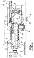
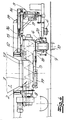
- 1 to 5 show sections of a longitudinal section through the lower part of a coal filling truck, which is in a Coke plant track-guided on the coke oven ceiling of one Coke oven battery is moved.
- the coal filling truck takes Coal from a coal tower and transported to the coking chambers of the coke oven battery.
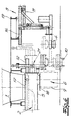
- 6 is also in longitudinal section a further embodiment of the invention Coal filling car shown.
- the coal filling truck shown in the figures has one funnel-shaped bottom outlet 1, a horizontal Screw conveyor 2 below the floor outlet 1 and a lid lifting device 3 for opening and closing of Greochdeckeln 4 of the coking chambers.
- To the basics Construction of the screw conveyor 2 include one of housing 5 which can be loaded at the top with an outlet connection on the underside 6, at least one rotatably mounted in the housing 5 Screw conveyor 7 and a flange-mounted on the housing 5 Screw conveyor drive 8.
- a Telescopic tube 9 connected, which the outlet 6th connects to an open fill hole 10.
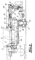
- the housing 5 of the screw conveyor 2 is on the underside of the coal filling car arranged horizontally movable and by means of an actuator 11 with unchanged Location of the coal filling truck between a starting position, in which the outlet port laterally to the fill hole is positioned offset, and a filling position, in which of the outlet nozzle 6 essentially with the filling hole 10 aligned, movable. 1 to 3 show the starting position, 4 and 5, the filling position of the Screw conveyor 2.
- the housing 5 of the screw conveyor 2 is guided on rails 12, which are on both sides of the housing 5 arranged on the steel substructure 13 of the coal filling car are.
- the cover lifting device 3 is on running rails 14 performed, which is also on the steel substructure 13 of the coal filling car are arranged.
- the running tracks 14 extend parallel to the guide rails 12 of the screw conveyor 2. Furthermore, one removes a comparative examination of the figures that the driving movements of the screw conveyor 2 along the guide rails 12 and the lid lifting device 3 along the Running rails are rigidly coupled.
- a hydraulic or electromechanical Setting device 11 is provided, which also on the steel substructure 13 of the coal filling car is arranged. She works on in the embodiment one attached to the housing 5 of the screw conveyor 2 Carrier 15. The cover lifting device is also on these connected by means of a coupling rod.
- the housing 5 of the screw conveyor 2 has an upper side Cover plate 17, which in the starting position of the screw conveyor 2 partially or the bottom outlet completely closed. The order is made that in the starting position no coal on the ceiling of the Coking chambers can leak.
- shut-off device e.g. in the form of a gate valve 18, arranged, by a device attached to the screw conveyor 19 can be actuated.
- the telescopic tube 9 is by means of the actuator 20 can be moved up and down automatically is.
- a vertically adjustable device 21 for cleaning the fill hole cover and fill hole frame connected is assigned to the outlet 6 end of the Screw conveyor housing 5 .
- the device 21 is together with the housing 5 between its starting position and its Filling position can be moved horizontally and is in the starting position settable on the frame of the filling hole 10.
- the Lid lifting device 3 is independent of the horizontal Adjustment movement of the screw conveyor housing 5 horizontally movable.
- the various functional positions of the device 21 are shown, partly in dashed lines, in FIG. 6.
- the Housing 5 of the screw conveyor 2 takes its starting position on.
- the Greochdeckel 4 is from the lid lifting device 3 has been added and is in one Position laterally offset from the fill hole.
- the lid lifting device 3 moves into the position shown in dashed lines and lowers the Filling hole cover 4 in the cleaning device 21.
- the cover lifting device moves 3 and the cleaning device 21 in the positions represented by solid lines. Subsequently can the screw conveyor 2 in its filling position moves and can the processes already described for coal filling.
Landscapes
- Chemical & Material Sciences (AREA)
- Engineering & Computer Science (AREA)
- Materials Engineering (AREA)
- Oil, Petroleum & Natural Gas (AREA)
- Organic Chemistry (AREA)
- Mechanical Engineering (AREA)
- General Engineering & Computer Science (AREA)
- Coke Industry (AREA)
Description
Die Erfindung betrifft einen Kohlefüllwagen zum Befüllen
von Verkokungskammern einer Koksofenbatterie, mit
Der Kohlefüllwagen ist schienengeführt auf der Decke der Verkokungskammern einer Koksofenbatterie verfahrbar. Er nimmt Einsatzkohle von einem Kohleturm auf und transportiert sie zu den Verkokungskammern, in welche sie durch Füllöcher eingefüllt wird. Moderne Kohlefüllwagen weisen ein Zwangsbeschickungssystem mit einem horizontalen Schneckenförderer unterhalb des Bodenauslasses auf. Ferner sind sie mit einer automatischen Deckelabhebevorrichtung zum Öffnen und Verschließen von Füllochdeckeln sowie mit einem Teleskoprohr, welches den Auslaßstutzen des Schneckenförderers mit dem geöffneten Fülloch verbindet, zur Vermeidung störender Emissionen während des Füllvorganges ausgerüstet. Die beschriebenen Einrichtungen erfordern eine große Einbauhöhe an der Unterseite des Kohlefüllwagens. Die örtlichen Verhältnisse bestehender Kokereianlagen lassen den Einsatz moderner Kohlefüllwagen mit den beschriebenen Einrichtungen oftmals nicht zu.The coal filling truck is guided on the ceiling of the Coking chambers of a coke oven battery can be moved. He picks up coal from a coal tower and transports it them to the coking chambers into which they go through Filling holes is filled. Modern coal filling trucks show a forced feed system with a horizontal Screw conveyor below the floor outlet. Further they are with an automatic lid lifting device for opening and closing fill hole lids as well as with a telescopic tube, which the outlet of the Screw conveyor connects to the open filling hole, to avoid disturbing emissions during the filling process equipped. The facilities described require a large installation height on the underside of the coal filling car. The local conditions of existing coking plants allow the use of modern coal filling trucks with the described facilities often too.
Bei einem aus DE-A 25 45 265 bekannten Kohlefüllwaren ist der Schneckenförderer mit einer geneigt angeordneten Förderschnecke schwenkbeweglich an einem an der Unterseite des Kohlefüllwagens verfahrbaren Träger aufgehängt. Das Gehäuse des Schneckenförderers ist ausreichend hoch ausgebildet, so daß sich innerhalb des Schneckenförderergehäuses ein Schüttkegel ausbilden kann. Die Anordnung erfordert ebenfalls eine große Einbauhöhe an der Unterseite des Kohlefüllwagens, die nicht immer zur Verfügung steht.In a coal filling product known from DE-A 25 45 265 the screw conveyor with an inclined arrangement Screw conveyor swiveling on one of the bottom suspended from the coal filling vehicle movable carrier. The The screw conveyor housing is sufficiently high trained so that is inside the screw conveyor housing can form a cone. The order also requires a large installation height at the bottom of the coal filling truck, which is not always available.
Der Erfindung liegt die Aufgabe zugrunde, einen Kohlefüllwagen des eingangs beschriebenen Aufbaus anzugeben, der sich durch eine niedrige Einbauhöhe für den Schneckenförderer sowie die Deckelabhebevorrichtung auszeichnet.The invention has for its object a coal filling truck of the structure described at the beginning, the low installation height for the screw conveyor and distinguishes the lid lifting device.
Die Aufgabe wird bei dem eingangs beschriebenen Kohlefüllwagen erfindungsgemäß dadurch gelöst, daß das Gehäuse des Schneckenförderers an der Unterseite des Kohlefüllwagens horizontal beweglich angeordnet sowie mittels eines Stellantriebs bei unverändertem Standort des Kohlefüllwagens zwischen einer Ausgangsstellung, in welcher der Auslaßstutzen seitlich zum Fülloch versetzt positioniert ist, und einer Füllstellung, in welcher der Auslaßstutzen im wesentlichen mit dem Fülloch fluchtet, bewegbar ist, wobei das Gehäuse des Schneckenförderers eine oberseitige Abdeckplatte aufweist, die in der Ausgangsstellung des Schneckenförderers den Bodenauslaß des Kohlefüllwagens so weit verschließt, daß keine Kohle auf die Decke der Verkokungskammern auslaufen kann. Der Schneckenförderer ist in Fahrtrichtung des Kohlefüllwagens ausgerichtet, wobei die Stellbewegung des Schneckenförderers in Form einer Axialbewegung in Längsrichtung des Schneckenförderers erfolgt. Der Stellweg des Schneckenförderergehäuses ist so eingerichtet, daß in einer ersten Arbeitsstellung (Ausgangsstellung) der Füllochdeckel frei zugänglich ist für die Deckelabhebevorrichtung und bei unverändertem Standort des Kohlefüllwagens in einer zweiten Arbeitsstellung (Füllstellung) der Auslaßstutzen im wesentlichen mit dem Fülloch fluchtet. Die erfindungsgemäße Anordnung ermöglicht es, den Auslaßstutzen so tief anzuordnen, dass durch das Teleskoprohr während des Befüllvorganges nur ein kleiner Abstand überbrückt werden muß. Das Teleskoprohr ist folglich mit sehr kurzer Baulänge ausführbar. Zusatzaggregate zur Betätigung des Teleskoprohres sind entsprechend ebenfalls als kompakte Aggregate ausführbar. Die Abdeckplatte des Schneckenförderers erfüllt die Funktion eines Schiebers, der den Bodenauslaß des Kohlefüllwagens verschließt und den Bodenauslaß nur freigibt, wenn die Befüllung einer Verkokungskammer erfolgt und der Schneckenförderer sich in der entsprechenden Füllstellung befindet.The task is described in the beginning Coal filling truck solved according to the invention in that the Housing of the screw conveyor at the bottom of the Coal filling truck arranged horizontally movable as well by means of an actuator with the location of the Charging car between a starting position, in which the outlet port is offset to the side of the fill hole is positioned, and a filling position in which the Outlet port is essentially aligned with the fill hole, is movable, the housing of the screw conveyor a Has top cover plate, which in the Starting position of the screw conveyor the bottom outlet of the Coal filling car closes so far that no coal on the coking chamber ceiling can leak. The Screw conveyor is in the direction of travel of the coal filling car aligned, the adjusting movement of the screw conveyor in the form of an axial movement in the longitudinal direction of the Screw conveyor takes place. The travel of the screw conveyor housing is set up so that in a first Working position (starting position) of the fill hole cover is free is accessible for the lid lifting device and at unchanged location of the coal filling truck in a second Working position (filling position) of the outlet nozzle in essentially aligned with the fill hole. The invention Arrangement allows the outlet port to be as deep arrange that through the telescopic tube during the Filling process can only be bridged a small distance got to. The telescopic tube is therefore very short executable. Additional units for operating the Telescopic tube are accordingly also as compact Executable units. The cover plate of the screw conveyor fulfills the function of a slide valve which Bottom outlet of the coal filling car closes and the Floor outlet only releases when filling a coking chamber takes place and the screw conveyor is in the corresponding filling position.
Gemäß einer bevorzugten Ausführung der Erfindung ist im Auslaßstutzen des Schneckenförderers ein Absperrorgan, z.B. in Form eines Absperrschiebers, angeordnet, das durch eine am Schneckenförderer befestigte Vorrichtung betätigbar ist. Am Umfang des Auslaßstutzens ist ferner eine Betätigungsvorrichtung angeordnet, mittels der das Teleskoprohr selbsttätig auf- und abwärts bewegt werden kann.According to a preferred embodiment of the invention A shut-off device, e.g. in the form of a gate valve, arranged by a device attached to the screw conveyor can be actuated. At the periphery of the outlet nozzle is also a Actuator arranged by means of which Telescopic tube can be moved up and down automatically can.
Das Gehäuse des Schneckenförderers ist zweckmäßig auf Schienen geführt, die beiderseits des Schneckenförderereine Betätigungsvorrichtung angeordnet, mittels der das Teleskoprohr selbsttätig auf- und abwärts bewegt werden kann.The housing of the screw conveyor is expedient Guided rails that run on both sides of the screw conveyor Actuator arranged by means of which Telescopic tube can be moved up and down automatically can.
Die Deckelabhebevorrichtung weist übliche Greif- und Hubeinrichtungen auf. Ferner ist eine Einrichtung erforderlich, um einen aufgenommenen Deckel aus dem Füllbereich herauszubewegen. Die Deckelabhebevorrichtung kann zu diesem Zweck mit einem separaten Antrieb ausgerüstet sein, die eine translatorische Bewegung oder eine horizontale Schwenkbewegung ausführt. Gemäß einer bevorzugten Ausführung der Erfindung ist die Deckelabhebevorrichtung auf an der Stahlunterkonstruktion des Füllwagens angeordneten Laufschienen geführt, wobei die Laufschienen sich parallel zu den Führungsschienen des Schneckenförderers erstrecken und Fahrbewegungen des Schneckenförderers entlang den Führungsschienen sowie der Deckelabhebevorrichtung entlang den Laufschienen starr gekoppelt sind. Es versteht sich, daß die starre Kopplung seitliche, durch die Schienenführungen bedingte Relativbewegungen zwischen dem Schneckenförderer und der Deckelabhebevorrichtung während der Fahrbewegung zuläßt. Zweckmäßigerweise wird eine Kupplungsstange mit Gelenklagern und Drehbolzen eingesetzt. Die Fahrbewegung des Schneckenförderers relativ zum Bodenauslaß wird bei dieser Ausführung der Erfindung auch genutzt, um einen Füllochdeckel, der von der Deckelabhebevorrichtung aufgenommen wurde, aus dem Arbeitsbereich des Fülloches herauszubewegen und nach beendeter Füllung wieder zum Fülloch hin zurückzubewegen. Gemäß einer bevorzugten konstruktiven Ausführung ist an der Stahlunterkonstruktion des Kohlefüllwagens eine hydraulische oder elektromechanische Stelleinrichtung angeordnet, die auf einen an dem Gehäuse des Schneckenförderers befestigten Träger arbeitet, und ist die Deckelabhebevorrichtung mittels einer Kupplungsstange ebenfalls mit dem Träger verbunden.The lid lifting device has conventional gripping and lifting devices on. A facility is also required around a picked-up lid from the filling area to move out. The lid lifting device can be used for this Purpose to be equipped with a separate drive that a translational movement or a horizontal one Pivots. According to a preferred embodiment the invention is the lid lifting device on the steel substructure of the filling truck Guided rails, the rails are parallel extend to the guide rails of the screw conveyor and travel movements of the screw conveyor along the guide rails and the lid lifting device along the Running rails are rigidly coupled. It is understood that the rigid coupling on the side, through the rail guides conditional relative movements between the screw conveyor and the cover lifting device during the movement allows. A coupling rod is expediently provided with Spherical bearings and pivot pins used. The driving movement of the screw conveyor relative to the bottom outlet is at this embodiment of the invention also used to Filling hole cover, which is taken up by the cover lifting device has been moved out of the work area of the fill hole and after the filling is finished again towards the filling hole to move back. According to a preferred design is on the steel substructure of the coal filling car a hydraulic or electromechanical control device arranged on a on the housing of the Auger mounted carrier works, and is the Lid lifting device also by means of a coupling rod connected to the carrier.
Gemäß einer weiteren, bevorzugten Ausführung der Erfindung ist an das dem Auslaßstutzen zugeordnete Ende des Schneckenförderergehäuses eine vertikal verstellbare Einrichtung zum Reinigen von Füllochdeckel und Füllochrahmen angeschlossen, die zusammen mit dem Gehäuse zwischen dessen Ausgangsstellung und dessen Füllstellung horizontal verfahrbar ist und in der Ausgangsstellung auf den Rahmen des Fülloches absetzbar ist. Bei dieser Ausführung der Erfindung ist die Deckelabhebevorrichtung nicht mit der Fahrbewegung des Schneckenförderers gekoppelt, sondern unabhängig von der horizontalen Stellbewegung des Schneckenförderergehäuses horizontal verfahrbar.According to a further preferred embodiment of the invention is at the end of the associated with the outlet Screw conveyor housing a vertically adjustable device for cleaning the fill hole cover and fill hole frame connected together with the housing between its Starting position and its filling position can be moved horizontally is and in the starting position on the frame of the Fülloches is deductible. In this embodiment of the invention the lid lifting device is not moving of the screw conveyor, but independent from the horizontal adjustment movement of the screw conveyor housing horizontally movable.
Im folgenden wird die Erfindung anhand einer lediglich ein Ausführungsbeispiel darstellenden Zeichnung ausführlich erläutert.In the following, the invention is based on only one Exemplary embodiment drawing explained in detail.
Die Fig. 1 bis 5 zeigen ausschnittsweise einen Längsschnitt durch den unteren Teil eines Kohlefüllwagens, der in einer Kokereianlage schienengeführt auf der Koksofendecke einer Koksofenbatterie verfahren wird. Der Kohlefüllwagen nimmt Einsatzkohle von einem Kohleturm auf und befördert diese zu den Verkokungskammern der Koksofenbatterie. Die Einsatzkohle wird dort durch Füllöcher in die Verkokungskammern vertikal eingefüllt. In Fig. 6 ist ebenfalls im Längsschnitt eine weitere Ausführung des erfindungsgemäßen Kohlefüllwagens dargestellt.1 to 5 show sections of a longitudinal section through the lower part of a coal filling truck, which is in a Coke plant track-guided on the coke oven ceiling of one Coke oven battery is moved. The coal filling truck takes Coal from a coal tower and transported to the coking chambers of the coke oven battery. The insert coal there through filling holes in the coking chambers filled vertically. 6 is also in longitudinal section a further embodiment of the invention Coal filling car shown.
Der in den Figuren dargestellte Kohlefüllwagen weist einen
trichterförmigen Bodenauslaß 1, einen horizontalen
Schneckenförderer 2 unterhalb des Bodenauslasses 1 sowie
eine Deckelabhebevorrichtung 3 zum Öffnen und Verschließen
von Füllochdeckeln 4 der Verkokungskammern auf. Zum grundsätzlichen
Aufbau des Schneckenförderers 2 gehören ein von
oben beschickbares Gehäuse 5 mit einem unterseitigen Auslaßstutzen
6, zumindest eine im Gehäuse 5 drehbar gelagerte
Förderschnecke 7 sowie ein an das Gehäuse 5 eingeflanschter
Förderschneckenantrieb 8. An den Auslaßstutzen 6 ist ein
Teleskoprohr 9 angeschlossen, welches den Auslaßstutzen 6
mit einem geöffneten Fülloch 10 verbindet.The coal filling truck shown in the figures has one
funnel-
Das Gehäuse 5 des Schneckenförderers 2 ist an der Unterseite
des Kohlefüllwagens horizontal beweglich angeordnet
sowie mittels eines Stellantriebes 11 bei unverändertem
Standort des Kohlefüllwagens zwischen einer Ausgangsstellung,
in welcher der Auslaßstutzen seitlich zum Fülloch
versetzt positioniert ist, und einer Füllstellung, in
welcher der Auslaßstutzen 6 im wesentlichen mit dem Fülloch
10 fluchtet, bewegbar. Die Fig. 1 bis 3 zeigen die Ausgangsstellung,
die Fig. 4 und 5 die Füllstellung des
Schneckenförderers 2. Das Gehäuse 5 des Schneckenförderers
2 ist auf Schienen 12 geführt, die beiderseits des Gehäuses
5 an der Stahlunterkonstruktion 13 des Kohlefüllwagens angeordnet
sind. Die Deckelabhebevorrichtung 3 ist auf Laufschienen
14 geführt, die ebenfalls an der Stahlunterkonstruktion
13 des Kohlefüllwagens angeordnet sind. Die Laufschienen
14 erstrecken sich parallel zu den Führungsschienen
12 des Schneckenförderers 2. Ferner entnimmt man
einer vergleichenden Betrachtung der Figuren, daß die Fahrbewegungen
des Schneckenförderers 2 entlang den Führungsschienen
12 sowie der Deckelabhebevorrichtung 3 entlang den
Laufschienen starr gekoppelt sind. Für die Verstellbewegung
des Schneckenförderers 2 ist eine hydraulische oder elektromechanische
Stelleinrichtung 11 vorgesehen, die ebenfalls
an der Stahlunterkonstruktion 13 des Kohlefüllwagens
angeordnet ist. Sie arbeitet im Ausführungsbeispiel auf
einem an dem Gehäuse 5 des Schneckenförderers 2 befestigten
Träger 15. An diesen ist auch die Deckelabhebevorrichtung
mittels einer Kupplungsstange angeschlossen.The
Das Gehäuse 5 des Schneckenförderers 2 weist eine oberseitige
Abdeckplatte 17 auf, die in der Ausgangsstellung
des Schneckenförderers 2 den Bodenauslaß 1 teilweise oder
vollständig verschließt. Die Anordnung ist so getroffen,
daß in der Ausgangsstellung keine Kohle auf die Decke der
Verkokungskammern auslaufen kann.The
Im Auslaßstutzen 6 des Schneckenförderers 2 ist ein Absperrorgan,
z.B. in Form eines Absperrschiebers 18, angeordnet,
das durch eine am Schneckenförderer befestigte Vorrichtung
19 betätigbar ist. Am Umfang des Auslaßstutzens 6
erkennt man ferner eine Betätigungsvorrichtung 20 für das
Teleskoprohr 9. Das Teleskoprohr 9 ist mittels der Betätigungsvorrichtung
20 selbsttätig auf- und abwärts bewegbar
ist. In the
Betrieb und Funktionsweise des erfindungsgemäßen Kohlefüllwagens
werden aus einer vergleichenden Betrachtung der
Figuren deutlich. Der Kohlefüllwagen nimmt in einem Kohleturm
der Kokereianlage Einsatzkohle auf, fährt zu einer
Verkokungskammer und wird dort an einem mit einem Füllochdeckel
4 verschlossenen Fülloch 10 positioniert (Fig. 1).
Während dieser Zeit nimmt das Gehäuse 5 des Schneckenförderers
2 die in Fig. 1 dargestellte Ausgangsstellung
ein. Nach der Positionierung des Kohlefüllwagens auf der zu
befüllenden Verkokungskammer erfolgt eine automatische
Füllochdeckelabhebung mittels der Deckelabhebevorrichtung
3. Das Erfassen und Anheben des Füllochdeckels 4 ist in den
Fig. 2 und 3 dargestellt. Es wird deutlich, daß der Bereich
oberhalb des Füllochdeckels 4 frei zugänglich ist und der
Schneckenförderer 2 mit Auslaßstutzen 6 und Teleskoprohr 9
die erforderliche Manipulation der Deckelabhebevorrichtung
3 nicht behindert. Nachdem der Füllochdeckel 4 angehoben
worden ist, werden das Gehäuse 5 des Schneckenförderers 2
und die Deckelabhebevorrichtung 3 in einer gemeinsamen
horizontalen Fahrbewegung translatorisch verfahren. Der
Stellweg ist so eingerichtet, daß der Auslaßstutzen 6 des
Schneckenförderers 2 schließlich die in Fig. 4 dargestellte
Füllstellung einnimmt, in welcher der Auslaßstutzen 6 im
wesentlichen mit dem Fülloch 10 fluchtet. Das Teleskoprohr
9 wird anschließend abgesenkt und eine Verbindung zwischen
dem Auslaßstutzen 6 und dem Fülloch 10 hergestellt.
Schließlich werden der im Auslaßstutzen 6 angeordnete Absperrschieber
18 geöffnet und der Förderschneckenantrieb 8
in Betrieb gesetzt. Damit beginnt die Kohleeinfüllung in
die Verkokungskammer durch die Förderschnecke 7. Operation and mode of operation of the coal filling vehicle according to the invention
are compared from a comparative perspective
Figures clearly. The coal filling truck takes in a coal tower
coal in the coke plant, drives to one
Coking chamber and is there on one with a
Bei der in Fig. 6 dargestellten Ausführung des Kohlefüllwagens
ist an das dem Auslaßstutzen 6 zuordnete Ende des
Schneckenförderergehäuses 5 eine vertikal verstellbare Einrichtung
21 zum Reinigen von Füllochdeckel und Füllochrahmen
angeschlossen. Die Einrichtung 21 ist zusammen mit
dem Gehäuse 5 zwischen dessen Ausgangsstellung und dessen
Füllstellung horizontal verfahrbar und ist in der Ausgangsstellung
auf den Rahmen des Fülloches 10 absetzbar. Die
Deckelabhebevorrichtung 3 ist unabhängig von der horizontalen
Stellbewegung des Schneckenförderergehäuses 5 horizontal
verfahrbar.In the embodiment of the coal filling vehicle shown in FIG. 6
is assigned to the
Die verschiedenen Funktionsstellungen der Einrichtung 21
sind, zum Teil gestrichelt, in der Fig. 6 dargestellt. Das
Gehäuse 5 des Schneckenförderers 2 nimmt seine Ausgangsstellung
ein. Der Füllochdeckel 4 ist von der Deckelabhebevorrichtung
3 aufgenommen worden und befindet sich in einer
seitlich zum Fülloch versetzten Position. Die Einrichtung
21 zum Reinigen von Füllochdeckel und Füllochrahmen wird
aus ihrer in durchgezogenen Linien dargestellten angehobenen
Position auf den Füllochrahmen abgesenkt und
reinigt dies. Die Deckelabhebevorrichtung 3 fährt in die
gestrichelt dargestellte Position vor und senkt den
Füllochdeckel 4 in die Reinigungseinrichtung 21 ab. Nach
Abschluß der Reinigungsvorgänge fahren die Deckelabhebevorrichtung
3 und die Reinigungsvorrichtung 21 in die mit
durchgezogenen Linien dargestellten Positionen zurück. Anschließend
kann der Schneckenförderer 2 in seine Füllstellung
bewegt und können die schon beschriebenen Vorgänge
für die Kohleeinfüllung eingeleitet werden.The various functional positions of the device 21
are shown, partly in dashed lines, in FIG. 6. The
Claims (7)
- A coal charging car for charging of coke oven chambers of a coke oven battery, said coal charging car comprised ofwith said screw conveyor (1) being comprised of a casing (5) chargeable from the top, equipped with a bottom outlet (6) located at the underside, provided with at least one worm conveyor (7) pivoted in a casing (5) as well as one worm conveyor drive (8) flanged to a casing (5), with a telescopic pipe (9) being connected to an outlet nozzle (6), said telescopic pipe closing the outlet nozzle (6) with an opened charging hole (10), characterized in that the casing of the screw conveyor (2) is positioned at the underside of a coal charging car to allow for being moved horizontally and being movable in unaltered position of the coal charging car by means of an actuating drive (11) between a home position in which the outlet nozzle (6) is positioned laterally staggered towards the charging hole (10) and a charging position in which the outlet nozzle (6) is mainly in alignment with the charging hole (10), said casing (5) of the worm conveyor (7) being provided with a top side cover plate (17) which, if said worm conveyor (7) is in its home position, seals the bottom outlet (1) of a coal charging car to such an extent that no coal can spill onto the top of coke oven chambers.a funnel-shaped bottom outlet (1)a horizontal screw conveyor (2) under the bottom outlet (1) anda lid lifting device (3) to open and close charging hole lids (4) of coke oven chambers,
- A coal charging car according to Claim 1, characterized in that a shutoff device (18) positioned in the outlet nozzle (6) of the screw conveyor (2) can be actuated by a device (19) fixed to said screw conveyor (2).
- A coal charging car according to Claim 1 or 2, characterized in that the telescopic pipe (9) is automatically movable in upward and downward direction by means of an actuating device (20) which is positioned at the perimeter of the outlet nozzle (6) of said screw conveyor (2).
- A coal charging car according to one of Claims 1 to 3, characterized in that the casing (5) of said screw conveyor (2) is guided on rails (12) which are positioned at both sides of the casing (5) at the steel substructure (13) of a coal charging car.
- A coal charging car according to one of Claims 1 to 4, characterized in that the lid lifting device (3) is guided on runner rails (14) positioned at the steel substructure (13) of a coal charging car, with the runner rails (14) extending in parallel to the guide rails (12) of said screw conveyor (2), and with the travel movements of said screw conveyor (2) along the guide rails (12) as well as those of the lid lifting device (3) along the runner rail (14) being rigidly coupled.
- A coal charging car according to Claim 5, characterized in that a hydraulic or electromechanical positioning device is arranged at the steel substructure (13) of a coal charging car, said positioning device working on a carrier (15) fixed to the casing of said screw conveyor (2), and that the lid lifting device (3) is also connected by means of a clutch bar (16) to said carrier (15).
- A coal charging car according to one of Claims 1 to 4, characterized in that a vertically adjustable device (21) for cleaning of charging hole lids and charging hole frames is connected to end of the screw conveyor casing (5) allocated to the outlet nozzle (6), wherein said device together with the casing (5) can be moved horizontally between its home position and its charging position and, when being in its home position, can be set down onto the frame of a charging hole (10).
Applications Claiming Priority (4)
| Application Number | Priority Date | Filing Date | Title |
|---|---|---|---|
| DE19741875 | 1997-09-23 | ||
| DE19741875 | 1997-09-25 | ||
| DE19743868A DE19743868C2 (en) | 1997-09-23 | 1997-10-04 | Charcoal filling truck for filling coking chambers of a coke oven battery |
| DE19743868 | 1997-10-04 |
Publications (3)
| Publication Number | Publication Date |
|---|---|
| EP0903393A2 EP0903393A2 (en) | 1999-03-24 |
| EP0903393A3 EP0903393A3 (en) | 1999-08-18 |
| EP0903393B1 true EP0903393B1 (en) | 2001-12-05 |
Family
ID=26040221
Family Applications (1)
| Application Number | Title | Priority Date | Filing Date |
|---|---|---|---|
| EP98115886A Expired - Lifetime EP0903393B1 (en) | 1997-09-23 | 1998-08-22 | Charging car for charging the chambers of a coke oven battery |
Country Status (5)
| Country | Link |
|---|---|
| US (2) | US6099229A (en) |
| EP (1) | EP0903393B1 (en) |
| BR (1) | BR9803970B1 (en) |
| CA (1) | CA2245380C (en) |
| PT (1) | PT903393E (en) |
Cited By (1)
| Publication number | Priority date | Publication date | Assignee | Title |
|---|---|---|---|---|
| AU2009211901B2 (en) * | 2008-02-07 | 2013-01-10 | Uhde Gmbh | Device on a coal charging car for lifting covers from filling hole frames in the furnace roof of a coke furnace and for cleaning the filling hole frames |
Families Citing this family (65)
| Publication number | Priority date | Publication date | Assignee | Title |
|---|---|---|---|---|
| US6290494B1 (en) * | 2000-10-05 | 2001-09-18 | Sun Coke Company | Method and apparatus for coal coking |
| DE10145431C2 (en) * | 2001-09-14 | 2003-11-13 | Thyssen Krupp Encoke Gmbh | Method and device for charging coke ovens from a coke oven battery |
| US7303597B2 (en) * | 2002-10-15 | 2007-12-04 | Pratt & Whitney Rocketdyne, Inc. | Method and apparatus for continuously feeding and pressurizing a solid material into a high pressure system |
| US7547419B2 (en) * | 2004-06-16 | 2009-06-16 | United Technologies Corporation | Two phase injector for fluidized bed reactor |
| US7360639B2 (en) * | 2004-06-16 | 2008-04-22 | Pratt & Whitney Rocketdyne, Inc. | Hot rotary screw pump |
| US7402188B2 (en) | 2004-08-31 | 2008-07-22 | Pratt & Whitney Rocketdyne, Inc. | Method and apparatus for coal gasifier |
| US7525202B2 (en) * | 2004-08-31 | 2009-04-28 | Microsoft Corporation | Quantum computational systems |
| US7547423B2 (en) * | 2005-03-16 | 2009-06-16 | Pratt & Whitney Rocketdyne | Compact high efficiency gasifier |
| US8196848B2 (en) | 2005-04-29 | 2012-06-12 | Pratt & Whitney Rocketdyne, Inc. | Gasifier injector |
| US7717046B2 (en) * | 2005-04-29 | 2010-05-18 | Pratt & Whitney Rocketdyne, Inc. | High pressure dry coal slurry extrusion pump |
| UA90089C2 (en) * | 2006-02-08 | 2010-04-12 | Григорий БЕРЕЗИН | Method for production of coke from the non-coking ranks of coal and the apparatus for its realization |
| DE102008008713B4 (en) * | 2008-02-11 | 2013-04-25 | Thyssenkrupp Uhde Gmbh | Device for filling furnace chambers of a coke oven |
| DE102008011552B4 (en) * | 2008-02-28 | 2012-08-30 | Thyssenkrupp Uhde Gmbh | Method and device for positioning control units of a coal filling car at filling openings of a coke oven |
| KR100948932B1 (en) | 2008-10-27 | 2010-03-23 | 주식회사 포스코 | Device for charging coal |
| US7998316B2 (en) | 2009-03-17 | 2011-08-16 | Suncoke Technology And Development Corp. | Flat push coke wet quenching apparatus and process |
| US8939278B2 (en) | 2010-04-13 | 2015-01-27 | Aerojet Rocketdyne Of De, Inc. | Deconsolidation device for particulate material extrusion pump |
| US8851406B2 (en) | 2010-04-13 | 2014-10-07 | Aerojet Rocketdyne Of De, Inc. | Pump apparatus including deconsolidator |
| US9200225B2 (en) | 2010-08-03 | 2015-12-01 | Suncoke Technology And Development Llc. | Method and apparatus for compacting coal for a coal coking process |
| KR20130094683A (en) * | 2010-08-09 | 2013-08-26 | 신포니아 테크놀로지 가부시끼가이샤 | Processed article feeding apparatus |
| US8307974B2 (en) | 2011-01-21 | 2012-11-13 | United Technologies Corporation | Load beam unit replaceable inserts for dry coal extrusion pumps |
| US8684151B2 (en) * | 2011-03-09 | 2014-04-01 | Sinfonia Technology Co., Ltd. | Raw material loading apparatus and pipe unit for raw material loading apparatus |
| EP2879777B1 (en) | 2012-07-31 | 2019-05-29 | SunCoke Technology and Development LLC | Methods for handling coal processing emissions and associated systems and devices |
| US9249357B2 (en) | 2012-08-17 | 2016-02-02 | Suncoke Technology And Development Llc. | Method and apparatus for volatile matter sharing in stamp-charged coke ovens |
| US9359554B2 (en) | 2012-08-17 | 2016-06-07 | Suncoke Technology And Development Llc | Automatic draft control system for coke plants |
| US9243186B2 (en) | 2012-08-17 | 2016-01-26 | Suncoke Technology And Development Llc. | Coke plant including exhaust gas sharing |
| US9169439B2 (en) | 2012-08-29 | 2015-10-27 | Suncoke Technology And Development Llc | Method and apparatus for testing coal coking properties |
| PL2898048T3 (en) | 2012-09-21 | 2020-11-16 | Suncoke Technology And Development Llc | Reduced output rate coke oven operation with gas sharing providing extended process cycle |
| US10047295B2 (en) | 2012-12-28 | 2018-08-14 | Suncoke Technology And Development Llc | Non-perpendicular connections between coke oven uptakes and a hot common tunnel, and associated systems and methods |
| WO2014105062A1 (en) | 2012-12-28 | 2014-07-03 | Suncoke Technology And Development Llc. | Systems and methods for removing mercury from emissions |
| US9273249B2 (en) | 2012-12-28 | 2016-03-01 | Suncoke Technology And Development Llc. | Systems and methods for controlling air distribution in a coke oven |
| US9476547B2 (en) | 2012-12-28 | 2016-10-25 | Suncoke Technology And Development Llc | Exhaust flow modifier, duct intersection incorporating the same, and methods therefor |
| US10883051B2 (en) | 2012-12-28 | 2021-01-05 | Suncoke Technology And Development Llc | Methods and systems for improved coke quenching |
| WO2014105065A1 (en) | 2012-12-28 | 2014-07-03 | Suncoke Technology And Development Llc. | Vent stack lids and associated systems and methods |
| US10760002B2 (en) | 2012-12-28 | 2020-09-01 | Suncoke Technology And Development Llc | Systems and methods for maintaining a hot car in a coke plant |
| US9238778B2 (en) | 2012-12-28 | 2016-01-19 | Suncoke Technology And Development Llc. | Systems and methods for improving quenched coke recovery |
| US9193915B2 (en) | 2013-03-14 | 2015-11-24 | Suncoke Technology And Development Llc. | Horizontal heat recovery coke ovens having monolith crowns |
| US9273250B2 (en) | 2013-03-15 | 2016-03-01 | Suncoke Technology And Development Llc. | Methods and systems for improved quench tower design |
| DE102013106473A1 (en) * | 2013-06-20 | 2014-12-24 | Thyssenkrupp Industrial Solutions Ag | Apparatus for cleaning a Fülllochrahmens in the furnace roof of a coke oven |
| BR112016015475B1 (en) | 2013-12-31 | 2021-02-17 | Suncoke Technology And Development Llc | decarbonization method of a coke deposit coke oven and coking system |
| US9932974B2 (en) | 2014-06-05 | 2018-04-03 | Gas Technology Institute | Duct having oscillatory side wall |
| US10526541B2 (en) | 2014-06-30 | 2020-01-07 | Suncoke Technology And Development Llc | Horizontal heat recovery coke ovens having monolith crowns |
| PL3186340T3 (en) | 2014-08-28 | 2021-04-19 | Suncoke Technology And Development Llc | Method and system for optimizing coke plant operation and output |
| RU2702546C2 (en) | 2014-09-15 | 2019-10-08 | САНКОУК ТЕКНОЛОДЖИ ЭНД ДИВЕЛОПМЕНТ ЭлЭлСи | Coke furnaces, having structure from monolithic components |
| WO2016109704A1 (en) | 2014-12-31 | 2016-07-07 | Suncoke Technology And Development Llc | Multi-modal beds of coking material |
| EP3240862A4 (en) | 2015-01-02 | 2018-06-20 | Suncoke Technology and Development LLC | Integrated coke plant automation and optimization using advanced control and optimization techniques |
| US11060032B2 (en) | 2015-01-02 | 2021-07-13 | Suncoke Technology And Development Llc | Integrated coke plant automation and optimization using advanced control and optimization techniques |
| JP6297015B2 (en) * | 2015-09-28 | 2018-03-20 | アイシン高丘株式会社 | Dissolving material supply device |
| WO2017117282A1 (en) * | 2015-12-28 | 2017-07-06 | Suncoke Technology And Development Llc | Method and system for dynamically charging a coke oven |
| RU2746968C2 (en) | 2016-06-03 | 2021-04-22 | САНКОУК ТЕКНОЛОДЖИ ЭНД ДИВЕЛОПМЕНТ ЭлЭлСи. | Methods and systems for automatic creation of corrective actions in an industrial facility |
| JP7154231B2 (en) | 2017-05-23 | 2022-10-17 | サンコーク テクノロジー アンド ディベロップメント リミテッド ライアビリティ カンパニー | Systems and methods for refurbishing coke ovens |
| BR112021012725B1 (en) | 2018-12-28 | 2024-03-12 | Suncoke Technology And Development Llc | METHOD FOR REPAIRING A LEAK IN A COKE OVEN OF A COKE OVEN, METHOD FOR REPAIRING THE SURFACE OF A COKE OVEN CONFIGURED TO OPERATE UNDER NEGATIVE PRESSURE AND HAVING AN OVEN FLOOR, AN OVEN CHAMBER AND A SINGLE CHIMNEY, AND METHOD OF CONTROLLING UNCONTROLLED AIR IN A SYSTEM FOR COAL COKE |
| WO2020140095A1 (en) | 2018-12-28 | 2020-07-02 | Suncoke Technology And Development Llc | Spring-loaded heat recovery oven system and method |
| WO2020140092A1 (en) | 2018-12-28 | 2020-07-02 | Suncoke Technology And Development Llc | Heat recovery oven foundation |
| BR112021012500B1 (en) | 2018-12-28 | 2024-01-30 | Suncoke Technology And Development Llc | UPCOMING COLLECTOR DUCT, EXHAUST GAS SYSTEM FOR A COKE OVEN, AND COKE OVEN |
| BR112021012718B1 (en) | 2018-12-28 | 2022-05-10 | Suncoke Technology And Development Llc | Particulate detection system for use in an industrial facility and method for detecting particulate matter in an industrial gas facility |
| BR112021012766B1 (en) | 2018-12-28 | 2023-10-31 | Suncoke Technology And Development Llc | DECARBONIZATION OF COKE OVENS AND ASSOCIATED SYSTEMS AND METHODS |
| BR112021012952A2 (en) | 2018-12-31 | 2021-09-08 | Suncoke Technology And Development Llc | METHODS AND SYSTEMS TO PROVIDE CORROSION RESISTANT SURFACES IN CONTAMINANT TREATMENT SYSTEMS |
| WO2020142389A1 (en) | 2018-12-31 | 2020-07-09 | Suncoke Technology And Development Llc | Improved systems and methods for utilizing flue gas |
| WO2021134071A1 (en) | 2019-12-26 | 2021-07-01 | Suncoke Technology And Development Llc | Oven health optimization systems and methods |
| EP4146767A4 (en) | 2020-05-03 | 2024-07-31 | Suncoke Technology and Development LLC | HIGH QUALITY COKE PRODUCTS |
| AU2022270111A1 (en) | 2021-05-04 | 2023-11-23 | Suncoke Technology And Development Llc | Foundry coke products, and associated systems and methods |
| US11946108B2 (en) | 2021-11-04 | 2024-04-02 | Suncoke Technology And Development Llc | Foundry coke products and associated processing methods via cupolas |
| EP4426799A4 (en) | 2021-11-04 | 2025-09-17 | Suncoke Tech & Development Llc | Cast coke products and related systems, devices and processes |
| US12110458B2 (en) | 2022-11-04 | 2024-10-08 | Suncoke Technology And Development Llc | Coal blends, foundry coke products, and associated systems, devices, and methods |
| US12410369B2 (en) | 2023-11-21 | 2025-09-09 | Suncoke Technology And Development Llc | Flat push hot car for foundry coke and associated systems and methods |
Family Cites Families (12)
| Publication number | Priority date | Publication date | Assignee | Title |
|---|---|---|---|---|
| US3142391A (en) * | 1961-07-17 | 1964-07-28 | Allied Chem | Coke oven charging machine having mechanism for removing and replacing charging hole covers |
| DE1671354B2 (en) * | 1968-03-05 | 1974-10-24 | Fa. Carl Still, 4350 Recklinghausen | Lowerable coal outlet under the filling bunkers of coking furnace filling wagons with locking devices |
| DE2509222A1 (en) * | 1975-03-04 | 1976-09-16 | Still Fa Carl | Coke oven charging car - has inclined worm conveyor pan, lifted and moved by actuators and with level and flap controls |
| DE2510097B1 (en) * | 1975-03-07 | 1976-09-16 | Hartung Kuhn & Co Maschf | COAL FILLER |
| DE2524462A1 (en) * | 1975-06-03 | 1976-12-16 | Still Fa Carl | COOKING OVEN FILLING TROLLEY |
| DE2545265C3 (en) * | 1975-10-09 | 1979-03-01 | Fa. Carl Still, 4350 Recklinghausen | Charging trolleys for coking ovens |
| US4151919A (en) * | 1977-10-18 | 1979-05-01 | Didier Engineering Gmbh. | Coke oven hopper truck including support for removable filling cover |
| DE2922571C2 (en) * | 1979-06-02 | 1985-08-01 | Dr. C. Otto & Co Gmbh, 4630 Bochum | Charging trolleys for coking ovens |
| DE3005994C2 (en) * | 1980-02-18 | 1982-08-12 | Gewerkschaft Schalker Eisenhütte, 4650 Gelsenkirchen | Coke oven charging car |
| DE3440277C1 (en) * | 1984-11-03 | 1986-05-22 | Siempelkamp Gießerei GmbH & Co, 4150 Krefeld | Process for introducing radioactive waste into a melting furnace and device for carrying out the process |
| DE4228191C1 (en) * | 1992-08-25 | 1993-11-04 | Hartung Kuhn & Co Maschf | DEVICE FOR FILLING COAL INTO THE OVEN CHAMBER OF A COOKING OVEN BATTERY |
| US5941445A (en) * | 1997-11-24 | 1999-08-24 | Bethlehem Steel Corporation | Apparatus for refurbishing a coke oven doorjamb |
-
1998
- 1998-08-22 EP EP98115886A patent/EP0903393B1/en not_active Expired - Lifetime
- 1998-08-22 PT PT98115886T patent/PT903393E/en unknown
- 1998-09-22 BR BRPI9803970-9A patent/BR9803970B1/en not_active IP Right Cessation
- 1998-09-23 US US09/159,487 patent/US6099229A/en not_active Expired - Lifetime
- 1998-09-23 CA CA002245380A patent/CA2245380C/en not_active Expired - Fee Related
-
2000
- 2000-06-02 US US09/586,155 patent/US6152668A/en not_active Expired - Lifetime
Cited By (1)
| Publication number | Priority date | Publication date | Assignee | Title |
|---|---|---|---|---|
| AU2009211901B2 (en) * | 2008-02-07 | 2013-01-10 | Uhde Gmbh | Device on a coal charging car for lifting covers from filling hole frames in the furnace roof of a coke furnace and for cleaning the filling hole frames |
Also Published As
| Publication number | Publication date |
|---|---|
| EP0903393A3 (en) | 1999-08-18 |
| CA2245380A1 (en) | 1999-03-23 |
| US6099229A (en) | 2000-08-08 |
| BR9803970A (en) | 1999-12-21 |
| BR9803970B1 (en) | 2011-04-19 |
| PT903393E (en) | 2002-05-31 |
| EP0903393A2 (en) | 1999-03-24 |
| US6152668A (en) | 2000-11-28 |
| CA2245380C (en) | 2005-11-15 |
Similar Documents
| Publication | Publication Date | Title |
|---|---|---|
| EP0903393B1 (en) | Charging car for charging the chambers of a coke oven battery | |
| DE102008008713A1 (en) | Device for filling furnace chambers of a coke oven | |
| DE102008008291B3 (en) | Device on a coal filling for lifting lids from Fülllochrahmen in the furnace roof of a coke oven and for cleaning the Fülllochrahmen | |
| DE2553386B2 (en) | Dust collector for a coke dry extinguishing system | |
| DE2142707C3 (en) | Trolley with devices for gripping, lifting, swiveling out, swiveling back and reinserting the hopper cover | |
| DE19743868C2 (en) | Charcoal filling truck for filling coking chambers of a coke oven battery | |
| DE102013104765B4 (en) | Transfer device for the transfer of fuel elements | |
| DE2545265C3 (en) | Charging trolleys for coking ovens | |
| EP0639213B1 (en) | Coke feed device with housing for a coke dry cooling installation | |
| DE2211571B2 (en) | Device for collecting and discharging the dust-laden gases produced when coke is printed out from coking ovens | |
| DE102013104761B4 (en) | Transfer device for the transfer of fuel elements | |
| DE2416151B1 (en) | ||
| DE2349289C3 (en) | ||
| EP4327910A1 (en) | Device for operating a water game | |
| EP0568636B1 (en) | Coke feed device for a coke dry cooling installation | |
| EP0085369A2 (en) | Process for the dry cooling of coke, and cooling chamber therefor | |
| EP1036746A1 (en) | Method for opening and closing an interchangeable container and device for performing the method | |
| DE102013104763B4 (en) | Transfer device for the transfer of fuel elements | |
| EP0036977B1 (en) | Tunnel-type furnace | |
| DE10145431A1 (en) | Method and device for charging coke ovens from a coke oven battery | |
| DE3916359C2 (en) | Device for the horizontal storage of lined-up fuel assemblies | |
| DE3528512C2 (en) | Coke oven door for horizontal chamber coking ovens | |
| DE3226783C2 (en) | Coking furnace | |
| WO1984000412A1 (en) | Device for loading a furnace, particularly a rotary drum furnace, with materials to be burned, particularly waste materials | |
| DE1517847A1 (en) | Bottom closure for lute tubs |
Legal Events
| Date | Code | Title | Description |
|---|---|---|---|
| PUAI | Public reference made under article 153(3) epc to a published international application that has entered the european phase |
Free format text: ORIGINAL CODE: 0009012 |
|
| AK | Designated contracting states |
Kind code of ref document: A2 Designated state(s): BE DE FR GB IT PT SE |
|
| AX | Request for extension of the european patent |
Free format text: AL;LT;LV;MK;RO;SI |
|
| PUAL | Search report despatched |
Free format text: ORIGINAL CODE: 0009013 |
|
| AK | Designated contracting states |
Kind code of ref document: A3 Designated state(s): AT BE CH CY DE DK ES FI FR GB GR IE IT LI LU MC NL PT SE |
|
| AX | Request for extension of the european patent |
Free format text: AL;LT;LV;MK;RO;SI |
|
| 17P | Request for examination filed |
Effective date: 19990904 |
|
| AKX | Designation fees paid |
Free format text: BE DE FR GB IT PT SE |
|
| 17Q | First examination report despatched |
Effective date: 20000331 |
|
| RAP1 | Party data changed (applicant data changed or rights of an application transferred) |
Owner name: THYSSEN KRUPP ENCOKE GMBH |
|
| GRAG | Despatch of communication of intention to grant |
Free format text: ORIGINAL CODE: EPIDOS AGRA |
|
| GRAG | Despatch of communication of intention to grant |
Free format text: ORIGINAL CODE: EPIDOS AGRA |
|
| GRAH | Despatch of communication of intention to grant a patent |
Free format text: ORIGINAL CODE: EPIDOS IGRA |
|
| GRAH | Despatch of communication of intention to grant a patent |
Free format text: ORIGINAL CODE: EPIDOS IGRA |
|
| GRAA | (expected) grant |
Free format text: ORIGINAL CODE: 0009210 |
|
| AK | Designated contracting states |
Kind code of ref document: B1 Designated state(s): BE DE FR GB IT PT SE |
|
| REG | Reference to a national code |
Ref country code: GB Ref legal event code: IF02 |
|
| GBT | Gb: translation of ep patent filed (gb section 77(6)(a)/1977) |
Effective date: 20011207 |
|
| REF | Corresponds to: |
Ref document number: 59802309 Country of ref document: DE Date of ref document: 20020117 |
|
| REG | Reference to a national code |
Ref country code: PT Ref legal event code: SC4A Free format text: AVAILABILITY OF NATIONAL TRANSLATION Effective date: 20020227 |
|
| PLBE | No opposition filed within time limit |
Free format text: ORIGINAL CODE: 0009261 |
|
| STAA | Information on the status of an ep patent application or granted ep patent |
Free format text: STATUS: NO OPPOSITION FILED WITHIN TIME LIMIT |
|
| 26N | No opposition filed | ||
| REG | Reference to a national code |
Ref country code: GB Ref legal event code: 732E |
|
| REG | Reference to a national code |
Ref country code: PT Ref legal event code: PC4A Owner name: UHDE GMBH, DE Effective date: 20060502 |
|
| REG | Reference to a national code |
Ref country code: FR Ref legal event code: TP |
|
| REG | Reference to a national code |
Ref country code: DE Ref legal event code: R082 Ref document number: 59802309 Country of ref document: DE Representative=s name: RAINER ALBRECHT, DE |
|
| REG | Reference to a national code |
Ref country code: DE Ref legal event code: R082 Ref document number: 59802309 Country of ref document: DE Representative=s name: ALBRECHT, RAINER, DIPL.-ING. DR.-ING., DE Effective date: 20120627 Ref country code: DE Ref legal event code: R081 Ref document number: 59802309 Country of ref document: DE Owner name: THYSSENKRUPP INDUSTRIAL SOLUTIONS AG, DE Free format text: FORMER OWNER: UHDE GMBH, 44141 DORTMUND, DE Effective date: 20120627 Ref country code: DE Ref legal event code: R081 Ref document number: 59802309 Country of ref document: DE Owner name: THYSSENKRUPP UHDE GMBH, DE Free format text: FORMER OWNER: UHDE GMBH, 44141 DORTMUND, DE Effective date: 20120627 |
|
| PGFP | Annual fee paid to national office [announced via postgrant information from national office to epo] |
Ref country code: SE Payment date: 20140820 Year of fee payment: 17 |
|
| PGFP | Annual fee paid to national office [announced via postgrant information from national office to epo] |
Ref country code: PT Payment date: 20140224 Year of fee payment: 17 |
|
| REG | Reference to a national code |
Ref country code: FR Ref legal event code: PLFP Year of fee payment: 18 |
|
| PGFP | Annual fee paid to national office [announced via postgrant information from national office to epo] |
Ref country code: DE Payment date: 20150821 Year of fee payment: 18 Ref country code: GB Payment date: 20150819 Year of fee payment: 18 |
|
| REG | Reference to a national code |
Ref country code: DE Ref legal event code: R082 Ref document number: 59802309 Country of ref document: DE Representative=s name: ALBRECHT, RAINER, DIPL.-ING. DR.-ING., DE Ref country code: DE Ref legal event code: R081 Ref document number: 59802309 Country of ref document: DE Owner name: THYSSENKRUPP INDUSTRIAL SOLUTIONS AG, DE Free format text: FORMER OWNER: THYSSENKRUPP UHDE GMBH, 44141 DORTMUND, DE |
|
| PGFP | Annual fee paid to national office [announced via postgrant information from national office to epo] |
Ref country code: BE Payment date: 20150819 Year of fee payment: 18 Ref country code: FR Payment date: 20150820 Year of fee payment: 18 |
|
| PGFP | Annual fee paid to national office [announced via postgrant information from national office to epo] |
Ref country code: IT Payment date: 20150824 Year of fee payment: 18 |
|
| REG | Reference to a national code |
Ref country code: PT Ref legal event code: MM4A Free format text: LAPSE DUE TO NON-PAYMENT OF FEES Effective date: 20160222 |
|
| REG | Reference to a national code |
Ref country code: SE Ref legal event code: EUG |
|
| PG25 | Lapsed in a contracting state [announced via postgrant information from national office to epo] |
Ref country code: PT Free format text: LAPSE BECAUSE OF NON-PAYMENT OF DUE FEES Effective date: 20160222 Ref country code: SE Free format text: LAPSE BECAUSE OF NON-PAYMENT OF DUE FEES Effective date: 20150823 |
|
| PG25 | Lapsed in a contracting state [announced via postgrant information from national office to epo] |
Ref country code: BE Free format text: LAPSE BECAUSE OF NON-PAYMENT OF DUE FEES Effective date: 20160831 |
|
| REG | Reference to a national code |
Ref country code: DE Ref legal event code: R119 Ref document number: 59802309 Country of ref document: DE |
|
| GBPC | Gb: european patent ceased through non-payment of renewal fee |
Effective date: 20160822 |
|
| REG | Reference to a national code |
Ref country code: FR Ref legal event code: ST Effective date: 20170428 |
|
| PG25 | Lapsed in a contracting state [announced via postgrant information from national office to epo] |
Ref country code: DE Free format text: LAPSE BECAUSE OF NON-PAYMENT OF DUE FEES Effective date: 20170301 Ref country code: FR Free format text: LAPSE BECAUSE OF NON-PAYMENT OF DUE FEES Effective date: 20160831 Ref country code: GB Free format text: LAPSE BECAUSE OF NON-PAYMENT OF DUE FEES Effective date: 20160822 |
|
| PG25 | Lapsed in a contracting state [announced via postgrant information from national office to epo] |
Ref country code: IT Free format text: LAPSE BECAUSE OF NON-PAYMENT OF DUE FEES Effective date: 20160822 |