EP1291709B1 - Ecran de projection a reflexion - Google Patents
Ecran de projection a reflexion Download PDFInfo
- Publication number
- EP1291709B1 EP1291709B1 EP02712359A EP02712359A EP1291709B1 EP 1291709 B1 EP1291709 B1 EP 1291709B1 EP 02712359 A EP02712359 A EP 02712359A EP 02712359 A EP02712359 A EP 02712359A EP 1291709 B1 EP1291709 B1 EP 1291709B1
- Authority
- EP
- European Patent Office
- Prior art keywords
- sheet
- projection screen
- front projection
- shading
- transparent
- Prior art date
- Legal status (The legal status is an assumption and is not a legal conclusion. Google has not performed a legal analysis and makes no representation as to the accuracy of the status listed.)
- Expired - Lifetime
Links
Images


Classifications
-
- G—PHYSICS
- G03—PHOTOGRAPHY; CINEMATOGRAPHY; ANALOGOUS TECHNIQUES USING WAVES OTHER THAN OPTICAL WAVES; ELECTROGRAPHY; HOLOGRAPHY
- G03B—APPARATUS OR ARRANGEMENTS FOR TAKING PHOTOGRAPHS OR FOR PROJECTING OR VIEWING THEM; APPARATUS OR ARRANGEMENTS EMPLOYING ANALOGOUS TECHNIQUES USING WAVES OTHER THAN OPTICAL WAVES; ACCESSORIES THEREFOR
- G03B21/00—Projectors or projection-type viewers; Accessories therefor
- G03B21/54—Accessories
- G03B21/56—Projection screens
- G03B21/60—Projection screens characterised by the nature of the surface
-
- E—FIXED CONSTRUCTIONS
- E06—DOORS, WINDOWS, SHUTTERS, OR ROLLER BLINDS IN GENERAL; LADDERS
- E06B—FIXED OR MOVABLE CLOSURES FOR OPENINGS IN BUILDINGS, VEHICLES, FENCES OR LIKE ENCLOSURES IN GENERAL, e.g. DOORS, WINDOWS, BLINDS, GATES
- E06B9/00—Screening or protective devices for wall or similar openings, with or without operating or securing mechanisms; Closures of similar construction
- E06B9/24—Screens or other constructions affording protection against light, especially against sunshine; Similar screens for privacy or appearance; Slat blinds
- E06B9/40—Roller blinds
- E06B9/42—Parts or details of roller blinds, e.g. suspension devices, blind boxes
-
- G—PHYSICS
- G02—OPTICS
- G02B—OPTICAL ELEMENTS, SYSTEMS OR APPARATUS
- G02B5/00—Optical elements other than lenses
- G02B5/02—Diffusing elements; Afocal elements
- G02B5/0205—Diffusing elements; Afocal elements characterised by the diffusing properties
- G02B5/021—Diffusing elements; Afocal elements characterised by the diffusing properties the diffusion taking place at the element's surface, e.g. by means of surface roughening or microprismatic structures
- G02B5/0226—Diffusing elements; Afocal elements characterised by the diffusing properties the diffusion taking place at the element's surface, e.g. by means of surface roughening or microprismatic structures having particles on the surface
-
- G—PHYSICS
- G02—OPTICS
- G02B—OPTICAL ELEMENTS, SYSTEMS OR APPARATUS
- G02B5/00—Optical elements other than lenses
- G02B5/02—Diffusing elements; Afocal elements
- G02B5/0273—Diffusing elements; Afocal elements characterized by the use
- G02B5/0284—Diffusing elements; Afocal elements characterized by the use used in reflection
-
- G—PHYSICS
- G03—PHOTOGRAPHY; CINEMATOGRAPHY; ANALOGOUS TECHNIQUES USING WAVES OTHER THAN OPTICAL WAVES; ELECTROGRAPHY; HOLOGRAPHY
- G03B—APPARATUS OR ARRANGEMENTS FOR TAKING PHOTOGRAPHS OR FOR PROJECTING OR VIEWING THEM; APPARATUS OR ARRANGEMENTS EMPLOYING ANALOGOUS TECHNIQUES USING WAVES OTHER THAN OPTICAL WAVES; ACCESSORIES THEREFOR
- G03B21/00—Projectors or projection-type viewers; Accessories therefor
- G03B21/54—Accessories
- G03B21/56—Projection screens
- G03B21/60—Projection screens characterised by the nature of the surface
- G03B21/602—Lenticular screens
Definitions
- the present invention relates to a front projection screen that displays an image projected by an image-projecting device, such as a slide projector, a liquid crystal projector or a moving picture projector.
- an image-projecting device such as a slide projector, a liquid crystal projector or a moving picture projector.
- Front projection screens for displaying images projected by a projector include white matrix screens, chemical etching screens, and high-luminance bead screens.
- white matrix screens When an image is projected on such a screen by a projector in a well-lighted room, the image cannot be displayed clearly due to the reduction of contrast or the loss of color balance. Therefore, room lights of the room must be turned off to darken the room.
- a high-luminance bead screen by a high-luminance projector a person is made to feel pains in the eyes by the glare of beads due to light regression when the person watches images displayed on the high-luminance bead screen for a long time.
- the term "light regression" signifies return of imaging light in a direction opposite to the traveling direction of projected imaging light.
- a composite screen proposed in JP-A No. 206620/2000 is capable of displaying an image of an excellent color balance without reducing the contrast of the image even in a light environment without requiring room lights to be turned off.
- This prior art composite screen is constructed by disposing a generally transparent, front shading sheet near a surface of a conventional front projection screen on the viewing side.
- the front shading sheet is provided with a plurality of horizontal, parallel, minute ridges having a triangular cross section in its front surface, and a shading layer is formed on one of the two sides of each ridge having a triangular cross section.
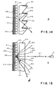
- Figs. 14 and 15 show a composite screen of the same construction as the screen disclosed in JP-A No. 206620/2000, formed by disposing a glass bead front projection screen analogous with a front projection screen embodying the present invention behind a front shading sheet.
- a front projection screen 33 is formed by bonding transparent glass beads 32 to the front surface of an opaque sheet 30 with a white, reflective adhesive layer 31.
- a front shading sheet 35 of a transparent material is disposed on the viewing side A of the front projection screen 33 such that an air gap 36 is formed between the front surface of the front projection screen 33 and the front shading sheet 35 to enable viewing images of an excellent color balance without reducing the contrast of images even in a light environment without turning off room lights.
- the front shading sheet 35 is provided with a plurality of horizontal, minute ridges 38 having a triangular cross section in its front surface, and a black shading layer 39 is formed on an upper side surface of each minute ridge 38.
- the front shading sheet 35 enables viewing images of an excellent color balance without reducing the contrast of the images owing to effects explained in JP-A No. 206620/2000 and to be explained later.
- imaging light rays R1 projected by a projector P disposed on the viewing side A travel straight through the front shading sheet 35, penetrate into the transparent glass bead 32, are reflected by the back surface of the transparent glass bead 32.
- the reflected imaging light rays emerge from the glass bead 32 travel through the air gap 36, enter the front shading sheet 35, are refracted by the front shading sheet 35, and emerge forward from the front shading sheet 35 in the directions of the arrows R2, R3, R4, R1, R5, R6 and R7.
- persons in a region between the arrows R2 and R7 are able to see an image formed by the imaging light rays projected by the projector P.
- the imaging light rays represented by the arrows R2, R3, R4, R1, R5, R6 and R7 include a large quantity of light including vertical components in addition to horizontal components.
- reflected light rays including both vertical components and horizontal components penetrate into the front shading sheet 35.
- Some of the reflected light rays incident on the front shading sheet 35 fall on the lower surface of the black shading layer 39 as shown in Fig. 14.
- the reflected light rays fallen on the lower surface of the black shading layer 39 are reflected totally on to the rear surface 41 of the front shading sheet 35 as indicated by the arrow Rt.
- the reflected rays are reflected again by the rear surface 41 and travel forward in the direction of the arrow Rt from the front shading sheet 35.
- Most of the reflected light rays fallen on the rear surface 41 at incident angles smaller than the critical angle travel rearward through the rear surface 41, while the reflected light rays fallen on the rear surface 41 at incident angles greater than the critical angle are totally reflected by the rear surface 41. Therefore, all the light rays Rt that emerge from parts of the front shading sheet 35 horizontally apart from the center of the front shading sheet 35 are reflected in a total reflection mode by the rear surface 41.
- the light rays Rt reflected by the rear surface 41 in a total reflection mode are dark light rays reflected by the lower surface of the black shading layer 39. Those dark light rays make an image formed by the light regressed from the transparent glass bead 32 turbid. It will be understood from the foregoing explanation that the dark light rays Rt emerge from parts horizontally apart from the center of the front shading sheet 35 because the light rays Rt fall on the rear surface 41 of the front shading sheet 35 at incident angles greater than the critical angle. Consequently, horizontal end parts of the image look dark to persons viewing the image from positions corresponding to horizontal end parts of the front shading sheet 35.
- the light rays Rt include both vertical components and horizontal components as a matter of course, the fact that the parts of the image displayed on horizontal end parts of the front shading sheet 35 look dark signifies that the viewing angle is small because it is possible that the viewing position changes greatly in horizontal directions while the viewing position does not change greatly in vertical directions.
- the present invention provides a front projection screen comprising: a front shading sheet facing a viewing side, wholly formed of a transparent material, having a front surface facing the viewing side, provided with a plurality of horizontal, parallel, minute ridges having a triangular cross section and each having a side surface coated with a shading layer; and a reflecting screen disposed opposite to a rear surface, facing a rear side opposite to the viewing side, of the front shading sheet; wherein a transparent filler layer formed of a material having a refractive index equal or nearly equal to that of the transparent material of the front shading sheet is sandwiched between the front shading sheet and the reflecting screen to construct a composite sheet such that any air layer is not formed at least between the front shading sheet and the transparent filler layer.
- the reflecting screen may include an opaque base sheet impermeable to light, a white, reflecting, adhesive layer formed on a front surface, facing the viewing side, of the base sheet, and many glass beads uniformly arranged on a front surface, facing the viewing side, of the white reflecting adhesive layer and formed of a material having a refractive index greater than that of the material of the transparent filler layer.
- the reflecting screen may include an opaque base sheet, and a white, mat sheet applied to a surface, facing the viewing side, of the opaque base sheet.
- the composite sheet may be flexible, and may be capable of being rolled in a roll and of being rolled out for use.
- the composite sheet may be flexible, and may be tautly set in a frame.
- the composite sheet of the front projection screen is provided on its rear surface with holding means capable of detachably holding the composite sheet on a wall, and a large screen may be constructed by closely arranging a plurality of front projection screens identical with the composite sheet on a wall.
- the front projection screen may further comprise connecting tabs projecting from sides of the composite sheet and capable of connecting the composite sheet to another identical composite sheet, and a large screen may be constructed by closely arranging a plurality of front projection screens identical with the front projection screen having the composite sheet provided with the connecting projections, and connecting together the plurality of front projection screens by the connecting tabs.
- Fig. 1 is a perspective view of a front projection screen in a first embodiment according to the present invention
- Fig. 2 is a longitudinal sectional view of the front projection screen shown in Fig. 1.
- the front projection screen in the first embodiment is a front projection screen of a light regression type that reflects projected imaging light so that the reflected imaging light travels in a direction opposite to the direction of travel of the projected imaging light.
- the reflected imaging light is caused to travel in a direction opposite to the direction of travel of the projected imaging light by the reflecting function of transparent glass beads 12, which will be described later.
- a front projection screen S in a first embodiment according to the present invention has a front shading sheet 5 wholly formed of a transparent material and facing a viewing side A.
- the front shading sheet 5 is formed of a transparent, flexible synthetic resin, such as a urethane resin.
- the front shading sheet 5 is provided in its front surface facing the viewing side A with horizontal, parallel minute ridges 8 arranged at pitches of, for example, about 0.2 mm.
- Each minute ridge 8 has a triangular cross section, and has an upper side surface 6 and a lower side surface 7.
- the lower side surface 7 is steeper than the upper side surface 6.
- the upper side surface 6 may be horizontal.
- the upper side surface 6 is coated with a black shading layer 9.
- the front shading sheet 5 has a flat rear surface 4.
- the rear surface 4, not facing the viewing side A, of the front shading sheet 5 is coated with a transparent filler layer 13 of a transparent filler having a refractive index equal or nearly equal to that of the transparent material of the front shading sheet 5.
- a reflecting screen RS is disposed behind the transparent filler layer 13.
- the respective refractive indices of the front shading sheet 5 and the transparent filler layer 13 are in the range of, for example, 1.45 to 1.65, and one of the indices may be greater than the other.
- the reflecting screen RS has a front layer formed by embedding transparent glass beads 12 having a refractive index greater than that of the transparent filler layer 13 in a plane in a uniform density in the transparent filler layer 13.
- the filler forming the transparent filler layer 13 is, for example, a resin having a refractive index smaller than that of the transparent glass beads 12.
- the transparent glass beads 12 are formed of a material having a large refractive index.
- the diameters of the transparent glass beads 12 are in the range of about 30 to about 70 ⁇ m, and may be different from each other.
- the refractive index of the transparent glass beads 12 is in the range of, for example, 1.9 to 2.12.
- the transparent glass beads 12 arranged embedded in a plane in the transparent filler layer 13 is coated with a white, reflecting adhesive layer 11, and an opaque base sheet 10 impermeable to light is applied to the reflecting adhesive layer 11.
- the base sheet 10 may be a fiber-reinforced plastic sheet formed by impregnating a glass cloth with a resin, such as a PVC resin (polyvinyl chloride resin), a PET resin (polyethylene terephthalate resin) or a polycarbonate resin.
- the transparent glass beads 12 arranged in a plane, the reflecting adhesive layer 11 and the base sheet 10 constitute the reflecting screen RS.
- the reflecting adhesive layer 11 enhances the diffusion of light by the interface between the reflecting adhesive layer 11 and the transparent glass beads 12.
- the front projection screen S has a shape generally resembling a sheet of composite construction.
- the front shading sheet 5 is formed of a flexible material
- the transparent filler layer 13 the reflecting adhesive layer 11 and the base sheet 10 are formed in flexible structures so that the front projection screen S is flexible. Any air layer is not formed in any parts of the front projection screen S, let alone between the front shading sheet 5 and the transparent filler layer 13.
- FIG. 2 An imaging light ray R projected on the front projection screen S by a projector P (Fig. 3) placed on the viewing side of the front projection screen S penetrates through the transparent lower side surface 7 of the front shading sheet 5 into the front shading sheet 5, passes through the transparent filler layer 13 and permeates the transparent glass bead 12. Then, as shown in Fig.
- the imaging light ray R is reflected in different directions by the rear surface of each transparent glass bead 12, the reflected imaging light beams travel forward through the transparent filler layer 13 and the front shading sheet 5, while the same are refracted at a boundary between the transparent glass bead 12 and the transparent filler layer 13 and at a boundary between the transparent filler layer 13 and the front shading sheet 5. Consequently, the reflected imaging light rays emerge from the front shading sheet 5 in different directions of the arrows R1 to R5, and a person on the viewing side A is able to see an image.
- the transparent filler layer 13 is in direct contact with the rear surface 4 of the front shading sheet 5, and the transparent filler layer 13 and the front shading sheet 5 are formed of materials respectively having refractive indices nearly equal to each other. Therefore, the transparent filler layer 13 and the front shading sheet 5 form a substantially homogeneous, continuous body.
- the emergence of the dark light rays Rt reflected rearward by the inner surface of the black shading layer 39, reflected by the rear surface 41 in a total reflection mode from parts horizontally apart from the center of the front shading sheet 35 of the front projection screen shown in Figs. 14 and 15 can be prevented.
- any dark light rays are not reflected forward by the rear surface 4 of the front shading sheet 5, light rays penetrate through the rear surface 4 into the transparent filler layer 13 and, consequently, any dark light rays emerge forward from the front shading sheet 5. Therefore, horizontal end parts of the image do not become dark.
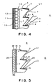
- Fig. 4 shows the effect of the black shading layer 9 of the front shading sheet 5 on raising the black level of the image by absorbing external light, such as illuminating light or outdoor light, fallen on the front surface of the front shading sheet 5 facing the viewing side A.
- An external light ray L1 fallen on the transparent lower side surface 7 of the minute ridge 8 having a triangular cross section is reflected by the lower side surface 7, and the reflected external light ray L2 is absorbed by the shading layer 9.
- External light rays L3 and L4 reflected by the lower side surface 7 are absorbed by the shading layer 9 formed on the upper side surface of the underlying minute ridge 8.
- An external light ray L5 penetrated into the front shading sheet 5 is reflected by the rear surface 4 in a total reflection mode and is absorbed by the shading layer 9 formed on the upper side surface.
- An external light ray L6 fallen directly on the shading layer 9 is absorbed by the same shading layer 9.
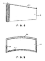
- Fig. 5 shows a front projection screen S in a second embodiment according to the present invention.
- the directionality of an imaging light reflected by the front projection screen S in the second embodiment differing from that of the imaging light reflected by the front projection screen S of the light regression type shown in Fig. 1, does not have a strong dependence on the direction of the projected light.
- the front projection screen S in the second embodiment has a front shading sheet 5 identical with that of the first embodiment shown in Fig. 2, and a reflecting screen RS different from that of the first embodiment shown in Fig. 2.
- the reflecting screen RS has a white, mat sheet 22, i.e., a white sheet having a satin-finished surface, contiguous with the transparent filler layer 13 of the front shading sheet 5, and an opaque film 20 applied to the rear surface of the white, mat sheet 22.
- the white, mat sheet 22 is bonded to the rear surface of the front shading sheet 5 with the transparent filler layer 13.
- a surface, contiguous with the transparent filler layer 13, of the white, mat sheet 22 is provided with minute irregularities. Fine particles are dispersed in the white, mat sheet 22 to enhance the diffusing effect of the white, mat sheet 22.
- the transparent filler layer 13, similarly to that of the first embodiment, is formed of a resin having a refractive index equal or nearly equal to that of the material of the front shading sheet 5.
- the white, mat sheet 22 has a thickness on the order of, for example, 0.1 mm.
- the white, mat sheet 22 is formed of a synthetic resin having a high reflectivity, such as a polyester resin or a styrene resin.
- the opaque film 20 is impermeable to light and is a black coating or a metallic mirror film formed by vapor deposition, such as an aluminum mirror film.
- the front projection screen S in the second embodiment shown in Fig. 5 is the same in function and effect as the front projection screen S in the first embodiment shown in Figs. 1 to 4.
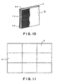
- the front projection screen S shown in Figs. 1 to 4, and the front projection screen S shown in Fig. 5 can be used in various modes. As shown in Figs. 6 and 7, the front projection screen S formed in a flexible sheet is wound on a horizontal take-up spool 50, and is rolled out by pulling the same downward for use. In Figs. 6 and 7, indicated at 51 is a weighting slat.
- a front projection screen S in a third embodiment according to the present invention is formed in a flexible sheet and is wound on a vertical take-up spool 52.
- the front projection screen S is rolled out by pulling the same laterally.
- a long, flexible shape-retaining member 53 is attached to the upper edge of the front projection screen S for shape retention.
- a front projection screen S in a fourth embodiment according to the present invention is formed in a rectangular, flexible sheet and is set in a rectangular frame 54.
- the front projection screen S is tensioned by a plurality of connecting members 55.
- the connecting members 55 may be connected to grommets or the like attached to the front projection screen S.
- the front projection screen S and the frame 54 are curved in a cylindrical shape.
- the front projection sheet S does not necessarily need to be a flexible sheet, but may be a hard structure capable of shape retention.
- Fig. 10 shows a rectangular front projection screen S in a fifth embodiment according to the present invention provided on its rear surface with magnetic rubber pads 56, i.e., holding means.
- Fig. 11 shows a large screen formed by closely arranging a plurality of front projection screen elements S similar to the front projection screen S shown in Fig. 10 on a support structure, such as a magnetic board or a magnetic partition board, and magnetically attaching the plurality of front projection screen elements S to the support structure.
- This large screen can be readily assembled and disassembled.
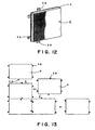
- Fig. 12 shows a rectangular, hard front projection screen S in a sixth embodiment according to the present invention capable of shape retention and provided on its rear surface with connecting tabs 58 and in its side with connecting holes.
- Fig. 13 is a view of assistance in explaining the construction of a large screen by closely arranging front projection screen elements S identical with the front projection screen S shown in Fig. 12. As shown in Fig. 13, the front projection screen elements S are closely arranged side by side, and the connecting tabs 58 of the front projection screen elements S are fitted in the connecting holes of the adjacent front projection screen elements S to construct a large screen. Thus, the large screen can be readily assembled and disassembled.
- the front projection screen includes the front shading sheet having the front surface facing the viewing side, provided with the plurality of horizontal, parallel, minute ridges having a triangular cross section, and each having the side surface coated with the shading layer; and the reflecting screen disposed opposite to the rear surface, facing the rear side opposite to the viewing side, of the front shading sheet; wherein the transparent filler layer formed of the material having a refractive index equal or nearly equal to that of the transparent material of the front shading sheet is sandwiched between the front shading sheet and the reflecting screen to construct the composite sheet such that any air layer is not formed at least between the front shading sheet and the transparent filler layer.
Landscapes
- Physics & Mathematics (AREA)
- General Physics & Mathematics (AREA)
- Optics & Photonics (AREA)
- Engineering & Computer Science (AREA)
- Structural Engineering (AREA)
- Architecture (AREA)
- Civil Engineering (AREA)
- Overhead Projectors And Projection Screens (AREA)
- Optical Elements Other Than Lenses (AREA)
Claims (7)
- Ecran de projection à réflexion (S) comprenant :dans lequel une couche transparente de remplissage (13) formée d'un matériau présentant un indice de réfraction égal ou approchant celui du matériau transparent de la feuille frontale d'estompage (5), est intercalé entre la feuille frontale d'estompage (5) et l'écran réfléchissant (11), pour constituer une feuille composite telle qu'aucune couche d'air n'est formée au moins entre la feuille frontale d'estompage (5) et la couche transparente de remplissage (13).une feuille frontale d'estompage (5) faisant face au côté d'observation (A), entièrement formée d'un matériau transparent, présentant une surface frontale faisant face au côté d'observation (A), prévue avec une pluralité de fines stries (7), horizontales et parallèles, présentant une section transversale triangulaire et comportant chacune une surface latérale (9) revêtue d'une couche d'estompage; etun écran réfléchissant (11) placé à l'opposé d'une surface arrière, faisant face à un côté arrière, opposé au côté d'observation de la feuille frontale d'estompage (5).
- Ecran de projection à réflexion selon la revendication 1, dans lequel l'écran réfléchissant (11,10) comprend :une feuille de base opaque (10) imperméable à la lumière;une couche adhésive, réfléchissante, blanche (11), formée sur une surface frontale de la feuille de base, faisant face au côté d'observation ;et un grand nombre de billes de verre (12) uniformément réparties sur une surface frontale, faisant face au côté d'observation (A), de la couche adhésive réfléchissante blanche (11), et formées d'un matériau présentant un indice de réfraction supérieur à celui du matériau de la couche transparente de remplissage (13).
- Ecran de projection à réflexion selon la revendication 1, dans lequel l'écran réfléchissant (10,11) inclut : une feuille de base opaque (10) et une feuille mate blanche (11) appliquée sur la surface, faisant face au côté d'observation, de la feuille de base opaque (10).
- Ecran de projection à réflexion selon l'une quelconque des revendications précédentes, dans lequel la feuille composite (5) est flexible, et a la capacité d'être enroulée en un rouleau (50) et enroulée hors service.
- Ecran de projection à réflexion selon l'une quelconque des revendications précédentes, dans lequel la feuille composite (S) est flexible, et est placée de manière tendue dans un cadre (54).
- Ecran de projection à réflexion selon l'une quelconque des revendications précédentes, comprenant en outre un moyen de fixation (56) capable de fixer la feuille composite sur un mur, de manière démontable, attaché à la surface arrière (10,11) de la feuille composite (S); dans lequel un grand écran peut être construit sur un mur en disposant l'un contre l'autre une pluralité d'écrans de projection frontaux (S) identiques à la feuille composite.
- Ecran de projection à réflexion selon l'une quelconque des revendications précédentes, comprenant en outre des pattes de connexion (58) débordant des côtés de la feuille composite (S) et capables d'attacher la feuille composite (S) à une autre feuille composite (S) identique ; dans lequel un grand écran peut être construit en disposant l'un contre l'autre une pluralité d'écrans de projection frontaux (S) identiques à l'écran de projection à réflexion (S) présentant la feuille composite prévue avec des saillies de connexion, et en attachant ensemble la pluralité d'écrans de projection frontaux (S) par les pattes de connexion (58).
Applications Claiming Priority (3)
| Application Number | Priority Date | Filing Date | Title |
|---|---|---|---|
| JP2001079403 | 2001-02-14 | ||
| JP2001079403 | 2001-02-14 | ||
| PCT/JP2002/001260 WO2002065208A1 (fr) | 2001-02-14 | 2002-02-14 | Ecran de projection a reflexion |
Publications (3)
| Publication Number | Publication Date |
|---|---|
| EP1291709A1 EP1291709A1 (fr) | 2003-03-12 |
| EP1291709A4 EP1291709A4 (fr) | 2003-05-28 |
| EP1291709B1 true EP1291709B1 (fr) | 2004-07-28 |
Family
ID=18935861
Family Applications (1)
| Application Number | Title | Priority Date | Filing Date |
|---|---|---|---|
| EP02712359A Expired - Lifetime EP1291709B1 (fr) | 2001-02-14 | 2002-02-14 | Ecran de projection a reflexion |
Country Status (8)
| Country | Link |
|---|---|
| US (1) | US6842282B2 (fr) |
| EP (1) | EP1291709B1 (fr) |
| JP (1) | JP4047172B2 (fr) |
| KR (1) | KR100719197B1 (fr) |
| CN (1) | CN100334503C (fr) |
| AT (1) | ATE272229T1 (fr) |
| DE (1) | DE60200820T2 (fr) |
| WO (1) | WO2002065208A1 (fr) |
Families Citing this family (60)
| Publication number | Priority date | Publication date | Assignee | Title |
|---|---|---|---|---|
| WO2004104694A1 (fr) * | 2003-05-26 | 2004-12-02 | Sharp Kabushiki Kaisha | Ecran de type a reflexion |
| GB0327819D0 (en) * | 2003-11-29 | 2003-12-31 | Lastolite Ltd | Improvements relating to projection screens |
| JP4087332B2 (ja) | 2003-12-25 | 2008-05-21 | 株式会社有沢製作所 | 反射型スクリーン |
| US7262911B2 (en) * | 2004-03-15 | 2007-08-28 | Arisawa Mfg. Co., Ltd. | Reflex-type screen assembly |
| KR101193096B1 (ko) * | 2004-07-09 | 2012-10-19 | 가부시키가이샤 다이신쿠 | 광학 필터 및 광학 필터의 제조 방법 |
| EP1774394B1 (fr) * | 2004-08-04 | 2011-12-28 | Fraunhofer-Gesellschaft zur Förderung der angewandten Forschung e.V. | Dispositif et procede de representation d'images statiques ou animees |
| JP2006053289A (ja) * | 2004-08-11 | 2006-02-23 | Seiko Epson Corp | スクリーン |
| US7224533B2 (en) * | 2004-11-08 | 2007-05-29 | Hewlett-Packard Development Company, L.P. | Optically retro-reflecting sphere |
| US7453634B2 (en) | 2005-03-07 | 2008-11-18 | Avery Dennison Corporation | Discontinuous or variable thickness gain modification coating for projection film and method for making same |
| KR100681415B1 (ko) * | 2005-06-01 | 2007-02-12 | 안희종 | 글라스비드 스크린 및 상기 스크린의 제작방법 |
| JP4793113B2 (ja) * | 2005-06-28 | 2011-10-12 | ソニー株式会社 | 反射型スクリーン |
| US7495828B2 (en) | 2005-11-23 | 2009-02-24 | Fusao Ishii | High contrast projection screen |
| US7911693B2 (en) * | 2006-03-20 | 2011-03-22 | Hewlett-Packard Development Company, L.P. | Ambient light absorbing screen |
| US20070253058A1 (en) * | 2006-05-01 | 2007-11-01 | Bright View Technologies, Inc. | Brightness enhancement structures including optical microstructures to provide elliptical diffusion patterns and methods of fabricating and operating the same |
| US7826134B2 (en) * | 2006-07-06 | 2010-11-02 | Hae-Yong Choi | High-definition sound-absorbing screen |
| US20080118241A1 (en) * | 2006-11-16 | 2008-05-22 | Tekolste Robert | Control of stray light in camera systems employing an optics stack and associated methods |
| US7570423B2 (en) * | 2007-01-25 | 2009-08-04 | Hewlett-Packard Development Company, L.P. | Projection screen |
| WO2008139914A1 (fr) * | 2007-05-09 | 2008-11-20 | Kuraray Co., Ltd. | Écran réflecteur et système d'affichage par projection vers l'avant |
| US20090027771A1 (en) * | 2007-07-27 | 2009-01-29 | Champion David A | Projection screen and method of making the same |
| JP4978436B2 (ja) * | 2007-11-19 | 2012-07-18 | セイコーエプソン株式会社 | スクリーン及び投射システム |
| JP5004090B2 (ja) * | 2007-11-30 | 2012-08-22 | 株式会社有沢製作所 | 反射型スクリーン及びスクリーン装置 |
| US7974005B2 (en) * | 2007-12-12 | 2011-07-05 | Texas Instruments Incorporated | Display screen for use in front projectors |
| US9118825B2 (en) * | 2008-02-22 | 2015-08-25 | Nan Chang O-Film Optoelectronics Technology Ltd. | Attachment of wafer level optics |
| JP5223541B2 (ja) * | 2008-08-26 | 2013-06-26 | セイコーエプソン株式会社 | 蒸着装置 |
| TWI378314B (en) * | 2008-10-15 | 2012-12-01 | Coretronic Corp | Screen of a projecting device |
| TWI369575B (en) * | 2008-10-24 | 2012-08-01 | Coretronic Corp | Projection screen |
| TWI368816B (en) * | 2008-10-24 | 2012-07-21 | Coretronic Corp | Reflective front projection screen |
| US8068277B2 (en) * | 2008-11-26 | 2011-11-29 | Lg Electronics Inc. | Reflective type screen using a spacer layer |
| US9419032B2 (en) | 2009-08-14 | 2016-08-16 | Nanchang O-Film Optoelectronics Technology Ltd | Wafer level camera module with molded housing and method of manufacturing |
| US8568002B2 (en) * | 2010-03-05 | 2013-10-29 | Southpac Trust International Inc., Trustee of the LDH Trust | Light diffusion and condensing fixture |
| TW201202837A (en) * | 2010-07-09 | 2012-01-16 | Coretronic Corp | Projection screen and manufacturing method thereof |
| JP2013050646A (ja) * | 2011-08-31 | 2013-03-14 | Dainippon Printing Co Ltd | 反射型スクリーン、及び反射型投射システム |
| KR20140064446A (ko) * | 2012-11-20 | 2014-05-28 | 삼성전자주식회사 | 프론트 프로젝션 디스플레이 장치용 반사형 스크린 |
| GB2518461A (en) | 2013-09-23 | 2015-03-25 | Barco Nv | Seamless display screen for fast installation |
| TWI506353B (zh) * | 2014-06-20 | 2015-11-01 | Delta Electronics Inc | 投影螢幕與應用其之投影系統 |
| CN105223766A (zh) * | 2014-07-04 | 2016-01-06 | 中强光电股份有限公司 | 投影屏幕以及投影屏幕的制作方法 |
| WO2016054795A1 (fr) * | 2014-10-10 | 2016-04-14 | 北京大学深圳研究生院 | Structure d'écran de projection orthographique de courte longueur focale |
| BE1023344B1 (fr) * | 2015-06-16 | 2017-02-09 | Tempora | Système de vidéo-projection à expérience visuelle augmentée |
| US10330832B2 (en) | 2015-06-25 | 2019-06-25 | Apple Inc. | High-luminance surface |
| US10928566B2 (en) | 2015-08-19 | 2021-02-23 | Apple Inc. | Transparent infrared reflective layer for a computing device |
| US10684397B2 (en) | 2015-09-08 | 2020-06-16 | Apple Inc. | Refractive coatings for a colored surface of an electronic device |
| WO2017058525A1 (fr) | 2015-09-29 | 2017-04-06 | Apple Inc. | Surfaces ayant des aspects optiques structurés |
| TWI581049B (zh) | 2015-12-24 | 2017-05-01 | 中強光電股份有限公司 | 投影屏幕 |
| CN107102509B (zh) | 2016-02-19 | 2020-05-26 | 台湾扬昕股份有限公司 | 投影屏幕 |
| CN107368491B (zh) * | 2016-05-12 | 2023-07-25 | 富泰华工业(深圳)有限公司 | 影像制作系统及方法 |
| US10114237B2 (en) | 2016-08-29 | 2018-10-30 | Apple Inc. | Surfaces with photonic crystal coatings and methods of customizing the visual appearance thereof |
| CN106554625A (zh) * | 2016-11-18 | 2017-04-05 | 石涛 | 填充液、该填充液的制备方法及应用 |
| US10574953B2 (en) | 2017-05-23 | 2020-02-25 | Sony Corporation | Transparent glass of polymer window pane as a projector screen |
| US10613428B2 (en) * | 2017-05-30 | 2020-04-07 | Sony Corporation | Wallpaper-based lenticular projection screen |
| US10429727B2 (en) | 2017-06-06 | 2019-10-01 | Sony Corporation | Microfaceted projection screen |
| CN108285679B (zh) * | 2017-07-18 | 2021-07-23 | 上海全鹰智能科技有限公司 | 一种大可视角的投影显示膜及其制备方法 |
| US10798331B2 (en) | 2017-07-21 | 2020-10-06 | Sony Corporation | Multichromic reflective layer to enhance screen gain |
| US10795252B2 (en) | 2017-07-21 | 2020-10-06 | Sony Corporation | Multichromic filtering layer to enhance screen gain |
| US10634988B2 (en) * | 2017-08-01 | 2020-04-28 | Sony Corporation | Tile-based lenticular projection screen |
| TWI686661B (zh) * | 2018-04-20 | 2020-03-01 | 億立材料有限公司 | 可多角度投影成像之投影幕 |
| CN110750029B (zh) * | 2018-07-06 | 2022-01-04 | 深圳光峰科技股份有限公司 | 投影屏幕 |
| KR102055183B1 (ko) | 2019-06-19 | 2019-12-12 | 박명구 | 2면 투사 스크린 장치 |
| CN110928131A (zh) * | 2019-12-06 | 2020-03-27 | 广东柯视丽科技有限公司 | 一种正投黑栅投影屏幕 |
| CN111627319A (zh) * | 2020-05-26 | 2020-09-04 | 深圳市真屏科技发展有限公司 | 防窥膜 |
| CN112987480A (zh) * | 2021-03-17 | 2021-06-18 | 成都比特王光学材料有限责任公司 | 一种高亮度微曲面投影屏 |
Family Cites Families (15)
| Publication number | Priority date | Publication date | Assignee | Title |
|---|---|---|---|---|
| US3510197A (en) * | 1966-12-09 | 1970-05-05 | Hitachi Ltd | Projection screen |
| DE2321428A1 (de) * | 1973-04-27 | 1974-11-14 | Mechanische Weberei Gmbh | Lichtbildprojektionswand |
| JPH04321017A (ja) * | 1991-04-19 | 1992-11-11 | Sharp Corp | 反射型スクリーン装置 |
| JPH0731233Y2 (ja) * | 1991-06-07 | 1995-07-19 | 丸山工業株式会社 | 映写用スクリーン |
| JP2814807B2 (ja) * | 1991-12-27 | 1998-10-27 | 松下電器産業株式会社 | 大画面映像表示用スクリーン装置と構成方法及びスクリーン接続部材 |
| JPH0675303A (ja) | 1992-08-26 | 1994-03-18 | Toppan Printing Co Ltd | 再帰反射性を有する反射型スクリーン |
| JPH06282009A (ja) * | 1993-03-29 | 1994-10-07 | Kodo Eizo Gijutsu Kenkyusho:Kk | 投写スクリーン |
| US5751387A (en) * | 1995-07-28 | 1998-05-12 | Fujitsu Limited | Fresnel lens and liquid crystal display device |
| JPH09274254A (ja) * | 1996-04-08 | 1997-10-21 | Izumi Kk | 映写スクリーン |
| GB9805198D0 (en) * | 1998-03-11 | 1998-05-06 | Maddock Alan | Portable visual display device |
| JPH11338056A (ja) * | 1998-05-22 | 1999-12-10 | Nissho Giken Kk | 映像表示装置 |
| JP2000206620A (ja) * | 1999-01-11 | 2000-07-28 | Nissho Giken Kk | 投映用スクリ―ン |
| US6304703B1 (en) * | 2000-01-13 | 2001-10-16 | Transvision, Inc. | Tiled fiber optic display apparatus |
| JP2002019385A (ja) * | 2000-07-06 | 2002-01-23 | Arisawa Optic Co Ltd | 投写スクリーン兼用白板 |
| JPWO2002056112A1 (ja) * | 2001-01-11 | 2004-08-12 | 株式会社アリサワ・オプテック | 背面透過型スクリーン |
-
2002
- 2002-02-14 US US10/257,291 patent/US6842282B2/en not_active Expired - Lifetime
- 2002-02-14 WO PCT/JP2002/001260 patent/WO2002065208A1/fr active IP Right Grant
- 2002-02-14 JP JP2002564666A patent/JP4047172B2/ja not_active Expired - Lifetime
- 2002-02-14 AT AT02712359T patent/ATE272229T1/de not_active IP Right Cessation
- 2002-02-14 EP EP02712359A patent/EP1291709B1/fr not_active Expired - Lifetime
- 2002-02-14 KR KR1020027013726A patent/KR100719197B1/ko active IP Right Grant
- 2002-02-14 DE DE60200820T patent/DE60200820T2/de not_active Expired - Lifetime
- 2002-02-14 CN CNB028011368A patent/CN100334503C/zh not_active Expired - Lifetime
Also Published As
| Publication number | Publication date |
|---|---|
| JP4047172B2 (ja) | 2008-02-13 |
| WO2002065208A1 (fr) | 2002-08-22 |
| DE60200820T2 (de) | 2005-07-14 |
| US6842282B2 (en) | 2005-01-11 |
| JPWO2002065208A1 (ja) | 2004-10-21 |
| CN100334503C (zh) | 2007-08-29 |
| EP1291709A1 (fr) | 2003-03-12 |
| ATE272229T1 (de) | 2004-08-15 |
| DE60200820D1 (de) | 2004-09-02 |
| KR100719197B1 (ko) | 2007-05-16 |
| US20030137728A1 (en) | 2003-07-24 |
| CN1461425A (zh) | 2003-12-10 |
| EP1291709A4 (fr) | 2003-05-28 |
| KR20020093907A (ko) | 2002-12-16 |
Similar Documents
| Publication | Publication Date | Title |
|---|---|---|
| EP1291709B1 (fr) | Ecran de projection a reflexion | |
| EP1288708B1 (fr) | Ecran a transmission cote verso | |
| JP3655972B2 (ja) | 反射型スクリーン及び前方投影システム | |
| JP2008076523A (ja) | 反射型スクリーン | |
| CN210894983U (zh) | 一种基于线性菲涅尔透镜的抗光屏幕结构 | |
| US4895429A (en) | Rear projection apparatus | |
| JP2005292679A (ja) | マイクロミラースクリーン | |
| JP2007293172A (ja) | フレネルレンズシートおよび透過型プロジェクションテレビ | |
| JPH09133971A (ja) | 背面プロジェクションtvセットの投射スクリーン | |
| JP2016062031A (ja) | 反射型スクリーン、映像表示システム | |
| JP2941292B2 (ja) | 背面投写形装置 | |
| EP1784688B1 (fr) | Ecran de rétroprojection | |
| JPH09160132A (ja) | 透過型スクリーン | |
| JP2008032777A (ja) | 光制御シート | |
| JPH0731233Y2 (ja) | 映写用スクリーン | |
| JPH075571A (ja) | 反射型の映写スクリーン | |
| JP2000111708A (ja) | レンズアレイシート | |
| JP2006106393A (ja) | 光拡散シートおよびプロジェクションスクリーン | |
| JP3357171B2 (ja) | マルチ映像装置用スクリーン | |
| CN211454223U (zh) | 光栅式抗光投影膜 | |
| JPH04119389A (ja) | 高輝度スクリーン | |
| JPH0743711Y2 (ja) | 背面投写型プロジェクションテレビのスクリーン | |
| CN211577653U (zh) | 超短焦硬幕 | |
| JPS62145233A (ja) | 反射型スクリ−ン用レンズシ−ト | |
| JPH10319507A (ja) | 平面型レンズ |
Legal Events
| Date | Code | Title | Description |
|---|---|---|---|
| PUAI | Public reference made under article 153(3) epc to a published international application that has entered the european phase |
Free format text: ORIGINAL CODE: 0009012 |
|
| 17P | Request for examination filed |
Effective date: 20021025 |
|
| AK | Designated contracting states |
Kind code of ref document: A1 Designated state(s): AT BE CH CY DE DK ES FI FR GB GR IE IT LI LU MC NL PT SE TR |
|
| AX | Request for extension of the european patent |
Extension state: AL LT LV MK RO SI |
|
| A4 | Supplementary search report drawn up and despatched |
Effective date: 20030411 |
|
| GRAP | Despatch of communication of intention to grant a patent |
Free format text: ORIGINAL CODE: EPIDOSNIGR1 |
|
| GRAJ | Information related to disapproval of communication of intention to grant by the applicant or resumption of examination proceedings by the epo deleted |
Free format text: ORIGINAL CODE: EPIDOSDIGR1 |
|
| RIN1 | Information on inventor provided before grant (corrected) |
Inventor name: WAKABAYASHI, YOSHIO Inventor name: TANAKA, KOJI Inventor name: FUKUDA, TATSUFUMI Inventor name: KURODA, KAZUMI |
|
| GRAP | Despatch of communication of intention to grant a patent |
Free format text: ORIGINAL CODE: EPIDOSNIGR1 |
|
| GRAS | Grant fee paid |
Free format text: ORIGINAL CODE: EPIDOSNIGR3 |
|
| RAP1 | Party data changed (applicant data changed or rights of an application transferred) |
Owner name: ARISAWA MFG. CO., LTD. |
|
| GRAA | (expected) grant |
Free format text: ORIGINAL CODE: 0009210 |
|
| AK | Designated contracting states |
Kind code of ref document: B1 Designated state(s): AT BE CH CY DE DK ES FI FR GB GR IE IT LI LU MC NL PT SE TR |
|
| PG25 | Lapsed in a contracting state [announced via postgrant information from national office to epo] |
Ref country code: IT Free format text: LAPSE BECAUSE OF FAILURE TO SUBMIT A TRANSLATION OF THE DESCRIPTION OR TO PAY THE FEE WITHIN THE PRESCRIBED TIME-LIMIT;WARNING: LAPSES OF ITALIAN PATENTS WITH EFFECTIVE DATE BEFORE 2007 MAY HAVE OCCURRED AT ANY TIME BEFORE 2007. THE CORRECT EFFECTIVE DATE MAY BE DIFFERENT FROM THE ONE RECORDED. Effective date: 20040728 Ref country code: LI Free format text: LAPSE BECAUSE OF FAILURE TO SUBMIT A TRANSLATION OF THE DESCRIPTION OR TO PAY THE FEE WITHIN THE PRESCRIBED TIME-LIMIT Effective date: 20040728 Ref country code: CH Free format text: LAPSE BECAUSE OF FAILURE TO SUBMIT A TRANSLATION OF THE DESCRIPTION OR TO PAY THE FEE WITHIN THE PRESCRIBED TIME-LIMIT Effective date: 20040728 Ref country code: FI Free format text: LAPSE BECAUSE OF FAILURE TO SUBMIT A TRANSLATION OF THE DESCRIPTION OR TO PAY THE FEE WITHIN THE PRESCRIBED TIME-LIMIT Effective date: 20040728 Ref country code: NL Free format text: LAPSE BECAUSE OF FAILURE TO SUBMIT A TRANSLATION OF THE DESCRIPTION OR TO PAY THE FEE WITHIN THE PRESCRIBED TIME-LIMIT Effective date: 20040728 Ref country code: FR Free format text: LAPSE BECAUSE OF FAILURE TO SUBMIT A TRANSLATION OF THE DESCRIPTION OR TO PAY THE FEE WITHIN THE PRESCRIBED TIME-LIMIT Effective date: 20040728 Ref country code: BE Free format text: LAPSE BECAUSE OF FAILURE TO SUBMIT A TRANSLATION OF THE DESCRIPTION OR TO PAY THE FEE WITHIN THE PRESCRIBED TIME-LIMIT Effective date: 20040728 Ref country code: TR Free format text: LAPSE BECAUSE OF FAILURE TO SUBMIT A TRANSLATION OF THE DESCRIPTION OR TO PAY THE FEE WITHIN THE PRESCRIBED TIME-LIMIT Effective date: 20040728 Ref country code: AT Free format text: LAPSE BECAUSE OF FAILURE TO SUBMIT A TRANSLATION OF THE DESCRIPTION OR TO PAY THE FEE WITHIN THE PRESCRIBED TIME-LIMIT Effective date: 20040728 |
|
| REG | Reference to a national code |
Ref country code: GB Ref legal event code: FG4D |
|
| REG | Reference to a national code |
Ref country code: CH Ref legal event code: EP |
|
| REG | Reference to a national code |
Ref country code: IE Ref legal event code: FG4D |
|
| REF | Corresponds to: |
Ref document number: 60200820 Country of ref document: DE Date of ref document: 20040902 Kind code of ref document: P |
|
| PG25 | Lapsed in a contracting state [announced via postgrant information from national office to epo] |
Ref country code: DK Free format text: LAPSE BECAUSE OF FAILURE TO SUBMIT A TRANSLATION OF THE DESCRIPTION OR TO PAY THE FEE WITHIN THE PRESCRIBED TIME-LIMIT Effective date: 20041028 Ref country code: SE Free format text: LAPSE BECAUSE OF FAILURE TO SUBMIT A TRANSLATION OF THE DESCRIPTION OR TO PAY THE FEE WITHIN THE PRESCRIBED TIME-LIMIT Effective date: 20041028 Ref country code: GR Free format text: LAPSE BECAUSE OF FAILURE TO SUBMIT A TRANSLATION OF THE DESCRIPTION OR TO PAY THE FEE WITHIN THE PRESCRIBED TIME-LIMIT Effective date: 20041028 |
|
| PG25 | Lapsed in a contracting state [announced via postgrant information from national office to epo] |
Ref country code: ES Free format text: LAPSE BECAUSE OF FAILURE TO SUBMIT A TRANSLATION OF THE DESCRIPTION OR TO PAY THE FEE WITHIN THE PRESCRIBED TIME-LIMIT Effective date: 20041108 |
|
| NLV1 | Nl: lapsed or annulled due to failure to fulfill the requirements of art. 29p and 29m of the patents act | ||
| LTIE | Lt: invalidation of european patent or patent extension |
Effective date: 20040728 |
|
| PG25 | Lapsed in a contracting state [announced via postgrant information from national office to epo] |
Ref country code: CY Free format text: LAPSE BECAUSE OF FAILURE TO SUBMIT A TRANSLATION OF THE DESCRIPTION OR TO PAY THE FEE WITHIN THE PRESCRIBED TIME-LIMIT Effective date: 20050214 Ref country code: IE Free format text: LAPSE BECAUSE OF NON-PAYMENT OF DUE FEES Effective date: 20050214 |
|
| REG | Reference to a national code |
Ref country code: CH Ref legal event code: PL |
|
| PG25 | Lapsed in a contracting state [announced via postgrant information from national office to epo] |
Ref country code: LU Free format text: LAPSE BECAUSE OF NON-PAYMENT OF DUE FEES Effective date: 20050228 Ref country code: MC Free format text: LAPSE BECAUSE OF NON-PAYMENT OF DUE FEES Effective date: 20050228 |
|
| PLBE | No opposition filed within time limit |
Free format text: ORIGINAL CODE: 0009261 |
|
| STAA | Information on the status of an ep patent application or granted ep patent |
Free format text: STATUS: NO OPPOSITION FILED WITHIN TIME LIMIT |
|
| 26N | No opposition filed |
Effective date: 20050429 |
|
| EN | Fr: translation not filed | ||
| REG | Reference to a national code |
Ref country code: IE Ref legal event code: MM4A |
|
| PG25 | Lapsed in a contracting state [announced via postgrant information from national office to epo] |
Ref country code: PT Free format text: LAPSE BECAUSE OF NON-PAYMENT OF DUE FEES Effective date: 20041228 |
|
| PGFP | Annual fee paid to national office [announced via postgrant information from national office to epo] |
Ref country code: DE Payment date: 20210202 Year of fee payment: 20 Ref country code: GB Payment date: 20210203 Year of fee payment: 20 |
|
| REG | Reference to a national code |
Ref country code: DE Ref legal event code: R071 Ref document number: 60200820 Country of ref document: DE |
|
| REG | Reference to a national code |
Ref country code: GB Ref legal event code: PE20 Expiry date: 20220213 |
|
| PG25 | Lapsed in a contracting state [announced via postgrant information from national office to epo] |
Ref country code: GB Free format text: LAPSE BECAUSE OF EXPIRATION OF PROTECTION Effective date: 20220213 |