EP1254981A2 - Vorrichtung zum Kräuseln von tuchartigem Material, insbesondere von textilem Material oder von Leder - Google Patents
Vorrichtung zum Kräuseln von tuchartigem Material, insbesondere von textilem Material oder von Leder Download PDFInfo
- Publication number
- EP1254981A2 EP1254981A2 EP02008985A EP02008985A EP1254981A2 EP 1254981 A2 EP1254981 A2 EP 1254981A2 EP 02008985 A EP02008985 A EP 02008985A EP 02008985 A EP02008985 A EP 02008985A EP 1254981 A2 EP1254981 A2 EP 1254981A2
- Authority
- EP
- European Patent Office
- Prior art keywords
- receiving part
- cloth
- bearing
- sewing
- support
- Prior art date
- Legal status (The legal status is an assumption and is not a legal conclusion. Google has not performed a legal analysis and makes no representation as to the accuracy of the status listed.)
- Granted
Links
Images



Classifications
-
- D—TEXTILES; PAPER
- D05—SEWING; EMBROIDERING; TUFTING
- D05B—SEWING
- D05B35/00—Work-feeding or -handling elements not otherwise provided for
- D05B35/08—Work-feeding or -handling elements not otherwise provided for for ruching, gathering, casing, or filling lace, ribbons, or bindings; Pleating devices; Cuttlers; Gathering feet; Crimpers; Curlers; Rufflers
Definitions
- the invention relates to a device in the preamble of Claim 1 mentioned and emerging from DE 200 00 099.3 U1 Art.
- the material to be crimped by a rotated, meshing gear pair passed through and then sewn with a fixing tape.
- the two gears as normal spur gears are designed, the material to be crimped can be strong Areas of curvature - for example at the corner areas of a vehicle seat - run outwards, i.e. towards the material edge.
- the Ripple process can be repeated in a time-consuming and cumbersome manner got to.
- the object of the invention is therefore in a device in the preamble of Claim type mentioned the gears of the gear pair in such a way to train them that even if there are strong edge curvatures Sewing material remain in engagement with it.
- the two gears are frustoconical and are engaged with each other at their largest diameter range, that will be to ripple, cloth-like material between the interlocking teeth of the only two linear gears - not like in the prior art relatively wide, cylindrical cylindrical spur gears - touched, so that with the Device according to the invention advantageously also with a cloth-like material a very strong area of curvature, even a meandering course, can be crimped, the gear pair always in the area of the cloth Material remains.
- the frustoconical design of the two gears in material pairing that is, in one from different Materials such as leather, nettle, fleece or the like existing crimp material with increasing gathering dimension an increased securing of the material pairing is achieved.
- the frustoconical design of the gears is very simple and to achieve in a cost-effective manner, that is to say without any significant additional effort.
- the bearing shaft is above lying gear rotatably supported in a bearing angle, this in turn is provided on a receiving part of the sewing machine height-displaceable.
- a perpendicular upward is at the end portion of the receiving part protruding bearing pin provided on which one in the bearing bracket rotatably inserted bearing sleeve is rotatably mounted.
- An adjustment system set out in claims 6 to 10 is self-regulating with regard to the material thickness of the sewing material and is also adjustable in the direction of the force of the presser foot and the designed contact pressure.
- the setting system consists of Essentially consisting of an upper side of the sewing material and approximately opposite Guide device lying on the underside, each with a material web adjacent roller.
- the guide device has one manually actuating and an automatically acting by spring force device.
- the guide device in turn has one above and one below the Material lies on the support bracket, the vertical leg of which has an elongated hole, which is penetrated by a clamping screw screwed into a stationary part.
- the support bracket can be clamped to an approximate dimension, while in screwed an adjusting screw into the free end section of the vertical leg is, which acts against the clamping screw via a pressure part, so that the altitude the guide device is adjustable to an exact dimension.
- a carried out by means of the crimping device according to the invention Crimping on a cloth-like material can be done in a rational manner and repeatable via a program-controlled handling machine be carried out, the crimping device on its swivel arm is appropriate.
- a gear of the device in the area Swivel arm of the handling machine can be driven in rotation.
- a gear wheel through the device a separate electric motor is driven in rotation (features of the claims 11 to 13).
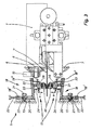
- the sewing head 1 shows a sewing head 1 of a sewing machine, the sewing head 1 has a presser foot 2 with a sewing drive 3. It is 2 in in a known manner with the cloth-like material a to be crimped in the vertical direction sewn to a fixing band b, as will be explained in the following.
- the cloth-like material a consists of textile material, leather or the like and is provided by a crimping device 5 provided on the end of the sewing head 1 ruffled, for which serve both gears 6 and 7, each are frustoconical in shape and in their largest diameter range are in gear-like use with one another, as shown in FIG. 1. Doing so one of the gears 6 and 7 by an electric motor, not shown, or in Area of the swivel arm of a handling machine by a flexible Shaft or the like rotated and the cloth-like material a through the meshing gear pair (gears 6 and 7) passed so that a Ripple c arises, as shown in FIG. 2.
- the bearing shaft 8 of the overhead gear 6 is over a bearing bush 8 'rotatably mounted in a bearing bracket 10, this is in turn provided on the upper side of the sewing head 1 so as to be displaceable in height.
- a bearing bracket 10 is a rack drive 14 in The directions of the double arrow d can be shifted in height.
- the Rack drive 14 in turn by one attached to the sewing head 1 Stepper motor 15 actuated.
- the bearing bracket 10 can also have a Not shown, electronically controlled adjustment mechanism in the directions of the Double arrow d can be shifted in height.
- the crimping device 5 has a guide device 17, which is provided on the upper side and approximately opposite on the underside of the cloth-like material a, each of which has a support bracket 18 with a vertical leg 18 'and an approximately horizontal leg 18 "
- an elongated hole 19 is provided in the vertical leg 18 'and extends through its longitudinal extension and is penetrated by a clamping screw 21 screwed into a fixed part 20.
- a pot-shaped receiving part 24 facing the cloth-like material a is fastened to the horizontal leg 18 " , in the interior of which there is a support part 26 which can be displaced in the directions of the double arrow e and has a cylindrical positioning section 26 ′′ .
- a guide pin 31 protrudes from the top thereof and penetrates a through bore 32 provided in the horizontal leg 18 ′′ of the support bracket 18 with radial play.
- the guide pin 31 is surrounded by a compression spring 33 which bears against the horizontal leg 18 ′′ and against the positioning section 26 ′′ with a prestress. This is delimited by a radially directed support shoulder 26 ′, to which a cylindrical guide section 26 ′′ adjoins, which passes through a circular recess 25 provided in the bottom 24 ′ of the receiving part 24.
- the action of the prestressed compression spring 33 means that the supporting part 26 lies in the 3 and 4, the rest position h shown on the support shoulder 26 'on the floor 24' of the receiving part 24.
- the holding portion 27 is adjoined to the guide section 26 "of the supporting part 26, into which a screw 28 is screwed, whereby a roller 30 'provided with a rubber jacket 30' is rotatably mounted thereon via a roller bearing 29.
- a number of locking grooves 34 are formed on the positioning section 26 ′′ .
- two free screws diametrically opposite and extending at right angles to its axis of rotation, are screwed onto the free end region of the receiving part 24 in each case a compression spring 36 is present, which in turn acts with a prestress against a locking ball 37 engaging in a rest position in a locking groove 34 of the positioning section 26 ′′ .
- the support part 26 can thus rotate about its axis of rotation in the directions of the double arrow f (FIGS. 4 and 5) are rotated, the latching balls 37 engaging in the respectively closest latching grooves 34 in the respectively achieved position of the roller 30 provided on the supporting part 26 for producing the crimp c on the cloth-like material a, so that the roller 30 in each optimal pivot position is fixed against pivoting.
Landscapes
- Engineering & Computer Science (AREA)
- Textile Engineering (AREA)
- Sewing Machines And Sewing (AREA)
- Treatment Of Fiber Materials (AREA)
Abstract
Description
- Fig. 1
- einen Nähkopf mit einer sich an diesem befindenden Kräuselvorrichtung in Vorderansicht,
- Fig. 2
- eine Ansicht in Pfeilrichtung A von Fig. 1,
- Fig. 3
- eine Gesamtvorderansicht von Nähkopf, Kräuselvorrichtung und Anstellsystem,
- Fig. 4
- eine vergrößerte Einzelansicht der obenliegenden Führungseinrichtung im Schnitt,
- Fig. 5
- eine schematische Darstellung in Draufsicht von Nähkopf, Kräuselvorrichtung und Anstellsystem.
Claims (13)
- Vorrichtung zum Kräuseln von tuchartigem Material, insbesondere von textilem Material oder von Leder, im Wesentlichen bestehend aus einem im Bereich des Nähfußes einer Nähmaschine vorgesehenen, in verzahnungsartigem Eingriff miteinander stehenden Zahnradpaar, dessen Lagerwellen etwa quer zur Transportrichtung des Nähguts verlaufen, wobei das tuchartige Material zur Erzeugung der Kräuselung durch das drehangetriebene Zahnradpaar hindurchgeführt und sodann mit einem Fixierband vernäht wird,
dadurch gekennzeichnet, dass die beiden Zahnräder (6 und 7) jeweils kegelstumpfförmig gestaltet sind und an ihrem größten Durchmesserbereich miteinander in Eingriff stehen. - Vorrichtung nach Anspruch 1, mit veränderbarem Achsabstand der Zahnräder,
dadurch gekennzeichnet, dass die Lagerwelle (8) des oben liegenden Zahnrads (6) in einem Lagerwinkel (10) drehbar gelagert ist, der seinerseits an einem Aufnahmeteil (Nähkopf 1) der Nähmaschine höhenverlagerbar vorgesehen ist. - Vorrichtung nach Anspruch 1 oder 2,
dadurch gekennzeichnet, dass am Endabschnitt des Aufnahmeteils (Nähkopf 1) ein lotrecht nach oben abstehender Lagerbolzen (12) befestigt ist, auf dem eine ihrerseits drehfest in den Lagerwinkel (10) eingesetzte Lagerhülse (13) drehbar gelagert ist. - Vorrichtung nach einem der Ansprüche 1 bis 3,
dadurch gekennzeichnet, dass der Lagerwinkel (10) durch einen Zahnstangenantrieb (14) höhenverlagerbar ist, der durch einen am Aufnahmeteil (Nähkopf 1) angebrachten Schrittmotor (15) betätigt ist. - Vorrichtung nach einem der Ansprüche 1 bis 4,
dadurch gekennzeichnet, dass der Lagerwinkel (10) über eine elektronisch gesteuerte Verstellmechanik höhenverlagert wird. - Vorrichtung nach einem der Ansprüche 1 bis 5,
gekennzeichnet durch eine am Nähgut (tuchartiges Material a) oberseitig und etwa gegenüberliegend unterseitig vorgesehene Führungseinrichtung (17), die jeweils eine an der Materialbahn (tuchartiges Material a) anliegende Laufrolle (30) aufweist, wobei die Führungseinrichtung eine manuell zu betätigende Vorrichtung (Klemmschraube 21 und Stellschraube 22) und eine durch Federkraft selbsttätig wirkende Vorrichtung (Tragteil 26) aufweist. - Vorrichtung nach einem der Ansprüche 1 bis 6,
dadurch gekennzeichnet, dass die Führungseinrichtung (17) jeweils einen obenliegenden und einen untenliegenden Tragwinkel (18) aufweist, dessen lotrechter Schenkel (18') von einem sich entsprechend seiner Längserstreckung verlaufenden Langloch (19) durchsetzt ist, das eine ihrerseits in ein ortsfestes Teil (20) eingeschraubte Klemmschraube (21) durchsetzt, wobei gegen diese über ein Druckteil (23) eine in den freien Endabschnitt des lotrechten Schenkels (18') eingeschraubte Stellschraube (22) wirkt. - Vorrichtung nach einem der Ansprüche 1 bis 7,
dadurch gekennzeichnet, dassvom waagrechten, etwa in der Bezugsebene des Nähguts (tuchartiges Material a) verlaufenden Schenkel (18") des Tragwinkels (18) der Führungseinrichtung (17) ein topfförmiges Aufnahmeteil (24) absteht, dessen eine Ausnehmung (25) aufweisender Boden (24') von einem gegen Federwirkung (Druckfeder 33) höhenverlagerbaren Tragteil (26) durchsetzt ist,vom Tragteil (26) ein seinerseits den waagrechten Schenkel (18") des Tragwinkels (18) höhenverlagerbar durchsetzender Führungsbolzen (31) absteht, der von einer mit Vorspannung am waagrechten Schenkel und am Tragteil anliegenden Druckfeder (33) umgeben ist, durch deren Wirkung das Tragteil in Ruhelage (h) über seine Auflageschulter (26') auf dem Boden (24') des Aufnahmeteils (24) aufliegt,das Tragteil (26) einen über das Aufnahmeteil (24) hinausragenden Haltefortsatz (27) aufweist, in den eine etwa parallel zum waagrechten Schenkel (18") des Tragwinkels (18) verlaufende Schraube (28) eingeschraubt ist, wobei auf dieser über ein Wälzlager (29) eine Laufrolle (30) drehbar gelagert ist. - Vorrichtung nach einem der Ansprüche 1 bis 8,
dadurch gekennzeichnet, dass am Tragteil (26) ein zylindrischer, die Ausnehmung (25) im Boden (24') des Aufnahmeteils (24) axial verlagerbar (Richtungen des Doppelpfeils e) durchsetzender Führungsabschnitt (26".) vorgesehen ist, an den sich über die radial gerichtete Auflageschulter (26') ein zylindrischer Positionierabschnitt (26"') anschließt, wobei an diesem eine Anzahl von jeweils in einem Winkelabstand voneinander angeordnete, axial verlaufende Rastnuten (34) ausgebildet sind. - Vorrichtung nach einem der Ansprüche 1 bis 9,
dadurch gekennzeichnet, dass am freien Endbereich des topfförmigen Aufnahmeteils (24) zumindest eine, etwa parallel zum waagrechten Schenkel (18") des Tragwinkels (18) verlaufende Stellschraube (35) eingeschraubt ist, an deren innenliegendem freien Ende eine Druckfeder (36) anliegt, welche mit Vorspannung gegen ein seinerseits in eine lotrechte Rastnut (34) des Positionierabschnitts (26"') eingreifendes Rastelement (Rastkugel 37) wirkt, wobei sich dieses in Ruhelage befindet. - Vorrichtung nach einem der Ansprüche 1 bis 10,
dadurch gekennzeichnet, dass eines der Zahnräder (6 oder 7) der Kräuselvorrichtung (5) durch einen Elektromotor drehangetrieben wird. - Vorrichtung nach einem der Ansprüche 1 bis 11,
dadurch gekennzeichnet, dass das an der Kräuselvorrichtung (5) vorgesehene Aufnahmeteil (Nähkopf 1) am Schwenkarm eines Handhabungsautomaten befestigt und über diesen programmgesteuert verlagerbar ist. - Vorrichtung nach einem der Ansprüche 1 bis 12,
dadurch gekennzeichnet, dass eines der Zahnräder (6 oder 7) der Kräuselvorrichtung (5) im Bereich des Schwenkarms des Handhabungsautomaten über eine biegsame Welle drehangetrieben wird.
Applications Claiming Priority (2)
| Application Number | Priority Date | Filing Date | Title |
|---|---|---|---|
| DE2001121669 DE10121669A1 (de) | 2001-05-04 | 2001-05-04 | Vorrichtung zum Kräuseln von tuchartigem Material, insbesondere von textilem Material oder von Leder |
| DE10121669 | 2001-05-04 |
Publications (3)
| Publication Number | Publication Date |
|---|---|
| EP1254981A2 true EP1254981A2 (de) | 2002-11-06 |
| EP1254981A3 EP1254981A3 (de) | 2004-01-02 |
| EP1254981B1 EP1254981B1 (de) | 2007-01-03 |
Family
ID=7683588
Family Applications (1)
| Application Number | Title | Priority Date | Filing Date |
|---|---|---|---|
| EP20020008985 Expired - Lifetime EP1254981B1 (de) | 2001-05-04 | 2002-04-23 | Vorrichtung zum Kräuseln von tuchartigem Material, insbesondere von textilem Material oder von Leder |
Country Status (2)
| Country | Link |
|---|---|
| EP (1) | EP1254981B1 (de) |
| DE (2) | DE10121669A1 (de) |
Family Cites Families (6)
| Publication number | Priority date | Publication date | Assignee | Title |
|---|---|---|---|---|
| GB477195A (en) * | 1937-01-30 | 1937-12-23 | David Almond Ltd | Improvements in or relating to sewing machines |
| US4070975A (en) * | 1975-11-26 | 1978-01-31 | U.S. Blind Stitch Machine Corporation | Ruffler attachment for sewing machine |
| DE8501084U1 (de) * | 1985-01-17 | 1985-04-11 | Josef Greulich Betriebs-GmbH, 8590 Marktredwitz | Naehmaschine mit kraeuselvorrichtung |
| US4811873A (en) * | 1987-05-18 | 1989-03-14 | Smock Right, Inc. | Self-stripping pleating apparatus |
| DE19634327A1 (de) * | 1996-08-24 | 1998-02-26 | Moll Automatische Naehsysteme | Vorrichtung zur Herstellung von Nähten |
| DE20000099U1 (de) * | 2000-01-04 | 2000-03-02 | KSL Keilmann Sondermaschinenbau GmbH, 64653 Lorsch | Vorrichtung zum Kräuseln tuchartigen Materials |
-
2001
- 2001-05-04 DE DE2001121669 patent/DE10121669A1/de not_active Withdrawn
-
2002
- 2002-04-23 DE DE50209125T patent/DE50209125D1/de not_active Expired - Fee Related
- 2002-04-23 EP EP20020008985 patent/EP1254981B1/de not_active Expired - Lifetime
Also Published As
| Publication number | Publication date |
|---|---|
| EP1254981B1 (de) | 2007-01-03 |
| DE50209125D1 (de) | 2007-02-15 |
| DE10121669A1 (de) | 2002-11-07 |
| EP1254981A3 (de) | 2004-01-02 |
Similar Documents
| Publication | Publication Date | Title |
|---|---|---|
| CH687996A5 (de) | Naehgutfuehrungsvorrichtung an einer Naehmaschine. | |
| DE3930562C1 (de) | ||
| DE3920783C1 (de) | ||
| DE3926329C2 (de) | ||
| DE1915472A1 (de) | Maehmaschine | |
| CH681093A5 (de) | ||
| DE834497C (de) | Naehmaschine | |
| DE3343615C2 (de) | Zwangsgesteuerte Taumelsiebmaschine | |
| EP1254981A2 (de) | Vorrichtung zum Kräuseln von tuchartigem Material, insbesondere von textilem Material oder von Leder | |
| DE2535317C2 (de) | Oberer Stoffschieber für Nähmaschinen | |
| DE19757934A1 (de) | Trimmvorrichtung für einen Rocksaum | |
| CH663173A5 (de) | Vorrichtung zum schnelleinspannen von skiern verschiedener breite. | |
| DE1951056A1 (de) | Vorrichtung zum selbsttaetigen und sicheren Herausfuehren einer durch magnetische Anziehung an eine Schablone angedrueckte,angetriebene Rolle aus den Innenecken der Schablone | |
| DE2706197A1 (de) | Markise | |
| DE3424712A1 (de) | Vorrichtung zum flaechigen auftragen pulverfoermiger produkte | |
| DE2035156C3 (de) | Vorrichtung zum Schleifen von Spiral bohrerspitzen | |
| DE102006026978B3 (de) | Kettenwirkmaschine | |
| DE2632132C2 (de) | Vorrichtung zum Schraubenschneiden einer Schlauchware | |
| DE102019133956B4 (de) | Nähmaschine mit einem abstandselement, und verwendung eines abstandselements in einer nähmaschine | |
| DE2551712C2 (de) | Nähmaschine | |
| DE644497C (de) | Pikiervorrichtung fuer Naehmaschinen | |
| DE2926410A1 (de) | Vorrichtung zum profilfraesen kreisbogenfoermig gekruemmter staebe | |
| DE151185C (de) | ||
| DE943925C (de) | Blindstichnaehmaschine | |
| DE2426538C2 (de) | Nähmaschine |
Legal Events
| Date | Code | Title | Description |
|---|---|---|---|
| PUAI | Public reference made under article 153(3) epc to a published international application that has entered the european phase |
Free format text: ORIGINAL CODE: 0009012 |
|
| AK | Designated contracting states |
Kind code of ref document: A2 Designated state(s): AT BE CH CY DE DK ES FI FR GB GR IE IT LI LU MC NL PT SE TR |
|
| AX | Request for extension of the european patent |
Free format text: AL;LT;LV;MK;RO;SI |
|
| PUAL | Search report despatched |
Free format text: ORIGINAL CODE: 0009013 |
|
| AK | Designated contracting states |
Kind code of ref document: A3 Designated state(s): AT BE CH CY DE DK ES FI FR GB GR IE IT LI LU MC NL PT SE TR |
|
| AX | Request for extension of the european patent |
Extension state: AL LT LV MK RO SI |
|
| 17P | Request for examination filed |
Effective date: 20040604 |
|
| AKX | Designation fees paid |
Designated state(s): DE FR GB |
|
| GRAP | Despatch of communication of intention to grant a patent |
Free format text: ORIGINAL CODE: EPIDOSNIGR1 |
|
| GRAS | Grant fee paid |
Free format text: ORIGINAL CODE: EPIDOSNIGR3 |
|
| GRAA | (expected) grant |
Free format text: ORIGINAL CODE: 0009210 |
|
| AK | Designated contracting states |
Kind code of ref document: B1 Designated state(s): DE FR GB |
|
| REG | Reference to a national code |
Ref country code: GB Ref legal event code: FG4D Free format text: NOT ENGLISH |
|
| REF | Corresponds to: |
Ref document number: 50209125 Country of ref document: DE Date of ref document: 20070215 Kind code of ref document: P |
|
| GBT | Gb: translation of ep patent filed (gb section 77(6)(a)/1977) |
Effective date: 20070207 |
|
| ET | Fr: translation filed | ||
| PLBE | No opposition filed within time limit |
Free format text: ORIGINAL CODE: 0009261 |
|
| STAA | Information on the status of an ep patent application or granted ep patent |
Free format text: STATUS: NO OPPOSITION FILED WITHIN TIME LIMIT |
|
| 26N | No opposition filed |
Effective date: 20071005 |
|
| PGFP | Annual fee paid to national office [announced via postgrant information from national office to epo] |
Ref country code: DE Payment date: 20090606 Year of fee payment: 8 Ref country code: FR Payment date: 20090429 Year of fee payment: 8 |
|
| PGFP | Annual fee paid to national office [announced via postgrant information from national office to epo] |
Ref country code: GB Payment date: 20090430 Year of fee payment: 8 |
|
| GBPC | Gb: european patent ceased through non-payment of renewal fee |
Effective date: 20100423 |
|
| REG | Reference to a national code |
Ref country code: FR Ref legal event code: ST Effective date: 20101230 |
|
| PG25 | Lapsed in a contracting state [announced via postgrant information from national office to epo] |
Ref country code: DE Free format text: LAPSE BECAUSE OF NON-PAYMENT OF DUE FEES Effective date: 20101103 |
|
| PG25 | Lapsed in a contracting state [announced via postgrant information from national office to epo] |
Ref country code: GB Free format text: LAPSE BECAUSE OF NON-PAYMENT OF DUE FEES Effective date: 20100423 |
|
| PG25 | Lapsed in a contracting state [announced via postgrant information from national office to epo] |
Ref country code: FR Free format text: LAPSE BECAUSE OF NON-PAYMENT OF DUE FEES Effective date: 20100430 |