EP1247706B1 - Anordnungsstruktur einer Diebstahlsicherung für Motorräder - Google Patents
Anordnungsstruktur einer Diebstahlsicherung für Motorräder Download PDFInfo
- Publication number
- EP1247706B1 EP1247706B1 EP20020252239 EP02252239A EP1247706B1 EP 1247706 B1 EP1247706 B1 EP 1247706B1 EP 20020252239 EP20020252239 EP 20020252239 EP 02252239 A EP02252239 A EP 02252239A EP 1247706 B1 EP1247706 B1 EP 1247706B1
- Authority
- EP
- European Patent Office
- Prior art keywords
- theft device
- motorcycle
- case
- receptacle
- structure according
- Prior art date
- Legal status (The legal status is an assumption and is not a legal conclusion. Google has not performed a legal analysis and makes no representation as to the accuracy of the status listed.)
- Expired - Fee Related
Links
Images


Classifications
-
- B—PERFORMING OPERATIONS; TRANSPORTING
- B60—VEHICLES IN GENERAL
- B60R—VEHICLES, VEHICLE FITTINGS, OR VEHICLE PARTS, NOT OTHERWISE PROVIDED FOR
- B60R25/00—Fittings or systems for preventing or indicating unauthorised use or theft of vehicles
- B60R25/10—Fittings or systems for preventing or indicating unauthorised use or theft of vehicles actuating a signalling device
- B60R25/102—Fittings or systems for preventing or indicating unauthorised use or theft of vehicles actuating a signalling device a signal being sent to a remote location, e.g. a radio signal being transmitted to a police station, a security company or the owner
-
- B—PERFORMING OPERATIONS; TRANSPORTING
- B60—VEHICLES IN GENERAL
- B60R—VEHICLES, VEHICLE FITTINGS, OR VEHICLE PARTS, NOT OTHERWISE PROVIDED FOR
- B60R25/00—Fittings or systems for preventing or indicating unauthorised use or theft of vehicles
- B60R25/20—Means to switch the anti-theft system on or off
- B60R25/2009—Antitheft state indicator
-
- B—PERFORMING OPERATIONS; TRANSPORTING
- B60—VEHICLES IN GENERAL
- B60R—VEHICLES, VEHICLE FITTINGS, OR VEHICLE PARTS, NOT OTHERWISE PROVIDED FOR
- B60R25/00—Fittings or systems for preventing or indicating unauthorised use or theft of vehicles
- B60R25/30—Detection related to theft or to other events relevant to anti-theft systems
- B60R25/33—Detection related to theft or to other events relevant to anti-theft systems of global position, e.g. by providing GPS coordinates
-
- B—PERFORMING OPERATIONS; TRANSPORTING
- B60—VEHICLES IN GENERAL
- B60R—VEHICLES, VEHICLE FITTINGS, OR VEHICLE PARTS, NOT OTHERWISE PROVIDED FOR
- B60R2325/00—Indexing scheme relating to vehicle anti-theft devices
- B60R2325/20—Communication devices for vehicle anti-theft devices
- B60R2325/205—Mobile phones
-
- B—PERFORMING OPERATIONS; TRANSPORTING
- B60—VEHICLES IN GENERAL
- B60R—VEHICLES, VEHICLE FITTINGS, OR VEHICLE PARTS, NOT OTHERWISE PROVIDED FOR
- B60R2325/00—Indexing scheme relating to vehicle anti-theft devices
- B60R2325/30—Vehicles applying the vehicle anti-theft devices
- B60R2325/304—Boats
-
- B—PERFORMING OPERATIONS; TRANSPORTING
- B60—VEHICLES IN GENERAL
- B60R—VEHICLES, VEHICLE FITTINGS, OR VEHICLE PARTS, NOT OTHERWISE PROVIDED FOR
- B60R2325/00—Indexing scheme relating to vehicle anti-theft devices
- B60R2325/30—Vehicles applying the vehicle anti-theft devices
- B60R2325/306—Motorcycles
-
- B—PERFORMING OPERATIONS; TRANSPORTING
- B60—VEHICLES IN GENERAL
- B60W—CONJOINT CONTROL OF VEHICLE SUB-UNITS OF DIFFERENT TYPE OR DIFFERENT FUNCTION; CONTROL SYSTEMS SPECIALLY ADAPTED FOR HYBRID VEHICLES; ROAD VEHICLE DRIVE CONTROL SYSTEMS FOR PURPOSES NOT RELATED TO THE CONTROL OF A PARTICULAR SUB-UNIT
- B60W2556/00—Input parameters relating to data
- B60W2556/45—External transmission of data to or from the vehicle
- B60W2556/50—External transmission of data to or from the vehicle for navigation systems
Definitions
- This invention relates to a structure for installing an anti-theft device in a motorcycle, particularly to a structure for installing in a motorcycle an anti-theft device comprising a communications device capable of reporting its current position by wireless transmitting at least identifying information.
- the vehicle anti-theft device taught by Japanese Patent No. 2,665,478 has a theft detector and a position detector installed in a vehicle. When the detector detects that the vehicle has been stolen, it activates the position detector to automatically transmit position information thereafter.
- a communications terminal can inform a person, such as its owner or administrator, located at remote location of its current position by wirelessly transmitting at least its identifying information by, when using the GPS, wirelessly transmitting its current position acquired from the GPS and its identifying information or, when using the PHS, wirelessly transmitting its identifying information.
- a motorcycle is exposed to the exterior substantially throughout and is also subject to considerably more vibration during driving than a car.
- the anti-theft device therefore has to be protected from rainwater etc. and to be isolated from vibration so as to protect it from vibration-induced failure. No installation structure that realistically satisfies these needs has yet been developed.
- the case can be cylindrical. Since the structure of the case enables the holder and the cover to be separated, the anti-theft device can be readily inserted into and removed from the case. Ease of maintenance is therefore enhanced.
- Materials with different properties can be utilized for the holder and the cover.
- the holder can be formed of a material with good anti-vibration property such as anti-vibration rubber and the cover can be formed of a material with good transparency property such as transparent resin. This simplifies case fabrication.
- the anti-theft device is installed between a wall of the receptacle and a lining sheet covering the wall.
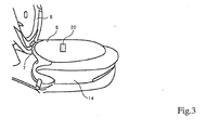
- This motorcycle has an engine 2 mounted at the approximate center of a body frame 1 that drives a rear wheel 4 through a powertrain 3 attached to the engine 2 to be vertically swingable.
- a storage box 5 for holding helmets H1, H2 or the like is mounted on the rear of the body frame 1 (above the rear wheel 4).
- a seat is attached over the storage box 5 by a hinge 7 at its forward edge so as to be movable between positions where it opens and closes the upper opening of the storage box 5.
- the anti-theft device 20 of this embodiment is illustrated in FIG. 5.
- the anti-theft device 20 can be waterproofed to a degree suitable for everyday purposes, secured by locking and concealed from sight by installing it in a lockable receptacle like the storage box 5, this embodiment enables installation that provides still higher levels of concealment, waterproofing and anti-vibration property by effecting the installation with the anti-theft device 20 enclosed in a case and also by implementing innovations in the installation structure.
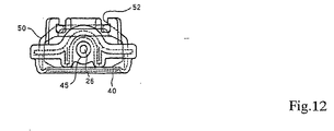
- the holder 40 of the case 30 formed of a material having elasticity and waterproofing property (e.g., rubber). It is formed of a base plate 41 and a surrounding upright wall 42 to have a boat-like shape.
- the base plate 41 is formed at multiple locations with ribs 43 for engaging with and positioning the anti-theft device 20 and with ribs 44 for engaging with and positioning the connector 25.
- One end of the wall 42 is formed with a cylindrical member 45 for passing the cord 26 extending from the connector 25.
- the cover 50 is attached to the holder 40 by engaging the hooks 51 with the gate-like lugs 46. When this engagement is established, watertightness is secured at the mating faces between the cover 50 and holder 40 owing to the intimate engagement produced by the elasticity of the rubber of the flange 53 fitted in the peripheral groove 48.
- the illustrated case 30 is fastened to the motorcycle body side by inserting it into a fastener 60 provided on the body side.
- the fastener 60 has a pair of hooks that fit into the gate-like lugs 47 of the case 30 to securely fasten the case 30 within the fastener 60 and thus to the motorcycle body side.
- the gate-like lugs 47 are, like the holder 40, formed of elastic rubber or the like, a vibration damping effect is obtained with respect to vibration from the motorcycle body side.
- the anti-theft device 20 housed in the case 30 is attached within a lockable storage portion provide in the motorcycle.
- a lockable storage portion provide in the motorcycle.
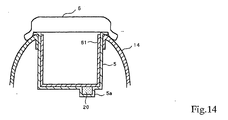
- it is mounted on the motorcycle using one of the structures shown in FIGs. 13 to 14, which show sectional views of the storage box 5 taken in the lateral direction of the motorcycle.
- the anti-theft device 20 When the anti-theft device 20 is in installed the storage box 5 that is lockably closable by the seat 6 in this manner, it can be prevented from detachment by an unauthorized person and be waterproofed to a degree suitable for everyday purposes. Since it is additionally covered by the lining sheet 61, moreover, a high degree of concealment is achieved. On the other hand, the user can easily check the indicator 21 of the anti-theft device 20 by opening the storage box 5 with a key and turning back the lining sheet 61.
- the anti-theft device 20 when the anti-theft device 20 is in installed the storage box 5 in this manner, it can be prevented from detachment by an unauthorized person and be waterproofed to a degree suitable for everyday purposes. Since it is additionally covered by the lining sheet 61, moreover, a high degree of concealment is achieved. On the other hand, the user can easily check the indicator 21.
- the arrangement has the further advantage that the floor of the storage box 5 can be maintained flat. This upgrades the utility of the storage box 5 and makes the location of the anti-theft device 20 even more difficult for someone else to discern.
- the anti-theft device 20 When the anti-theft device 20 is installed in the space between the storage box 5 and the rear cover 14 in this manner, it can be prevented from detachment by an unauthorized person, be waterproofed to a degree suitable for everyday purposes and be well concealed Moreover, the user can easily visually check the indicator 21 by a simple operation of undoing the screw plugs 5b and removing the storage box 5.
- any of various other lockable sites can also be used as the place for installation of the anti-theft device 20. It can, for example, be mounted in a storage box with lockable cover provided in the front cover 12 or the center cover 13, or in a tool storage space or the like formed between the motorcycle body and a seat that can be locked to the body.
- the anti-theft device 20 inside the case 30 can be protected from vibration by the elasticity of the holder 40 if the case 30 is attached to the motorcycle body side by its holder 40 side.
- the vibration propagation path can be made indirect and the elasticity enhanced to realize better vibration damping effect.
- a further improvement in anti-vibration effect can be achieved by adopting a vibration-damping structure utilizing additional elastic bodies.
- the transmission of vibration to the case 30 (and the anti-theft device 20 inside) can be reduced by, for example, forming a large number of conical elastic projections 49 on the bottom surface of the holder 40 and placing the case 30 so that the easily deformed tip portions of the elastic projections 49 are in contact with and deformable by the inner wall surface of the storage box 5.
- the effect of reducing vibration transmission can be further increased by forming peripheral grooves 48 at the bases of the conical elastic projections 49 so as to increase the deformability of the elastic projections 49.
- the flange 53 formed on the cover 50 is snuggly fitted in the peripheral groove 48 formed at the outer periphery of the wall 42, and the projecting ridge 45a formed in the cylindrical member 45 is bitingly engaged with the cord 26, invasion of water into the interior of the case 30 is prevented even during extraordinary circumstances as when the motorcycle is hosed down.
- a waterproofing structure such as that shown in FIG 16, it becomes possible to prevent condensation of moisture inside the case 30.
- the flange 53 forms an eave that prevents water from entering the peripheral groove 48a, while the labyrinth passage formed by the staggered projections 48b and notches formed in a wall 54 allows moisture inside the case 30 to escape to the exterior.
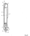
- FIG. 17 shows the configuration of an onboard charger 27 suitable for use with the anti-theft device 20 installed in the motorcycle.
- An internal battery 71 of the anti-theft device 20 is connected to the onboard charger 27 through an internal transformer 72 and the cord 26.
- the onboard charger 27 is connected to the onboard battery 10 by a cord 28.
- the voltage of the onboard battery 10 is transformed (stepped down from 12V to 5.2V, for example) by a transformer 73 in the onboard charger 27 and then transformed (stepped down from 5.2V to 4.2V, for example) by the internal transformer 72, whereafter it is used to charge the internal battery 71.
- the control circuit (e.g., microcomputer) of the anti-theft device 20 may be prevented from periodically entering sleep mode, i.e., may not enter the low power consumption operating mode but operate continuously to consume a large amount of energy. As this would put a drain on the onboard battery 10, it might become a major problem in the case of a motorcycle whose onboard battery 10 is of relatively small capacity.
- the service life of the internal battery 71 will be affected if charging is conducted under high-temperature condition of 40°C or higher or under low-temperature condition of -5°C or below.
- the internal transformer 72 is therefore designed not to charge the internal battery 71 under such temperature conditions. In fact, however, the likelihood of the motorcycle being used or stored under such high or low temperature conditions is high.
- the control unit 75 used can be one that controls the charge condition checking process so as to check the charge condition of the internal battery 71 at normal intervals (e.g., once every 36 hours), shorten the check interval (e.g., to once every 6 hours) if the result in a prescribed number of consecutive checks (e.g. 3 checks) is that the battery cannot be charged, decide that the internal battery 71 or the anti-theft device 20 is faulty if the result in a prescribed number of these checks (e.g., 5 checks) consecutively indicate that the battery cannot be charged , and upon deciding that a fault has occurred issue a warning through the indicator 21 or set off an audible alarm.
- a prescribed number of consecutive checks e.g. 3 checks
- the fact that the normal check interval is set at 36 hours means that if, for example, a charge condition check is made during the heat of a summer day, the next charge condition check will be made in the cool of the morning. As a result, the ratio of charge condition checks and battery chargings conducted under suitable temperature conditions is increased.
- the processing for this control can be viewed as an invention of a battery charging method or battery charger that carries out charge condition checks at preset intervals under the control of a microcomputer-based control unit 75 that conducts control processing in accordance with a prescribed program.
- the interval between charge condition checks and the method for controlling the interval can be defined in any of various ways. Typical ones are explained further in the following.
- the time offset (i.e., interval) can be set to any of various time periods.
- the interval should preferably be set at a value by obtained by dividing 24 hours (1 day) by a natural number not smaller than 2. Among these preferable interval values (12, 8, 6, ...), 6 hours is particularly preferable.
- the interval is preferably defined so that the offset is a natural number multiple of 6 hours.
- a battery charging operation is conducted.
- the charging operation is conducted while monitoring the battery voltage and current values and can be continued up to full charge, or be continued until the charged amount of power becomes substantially equal to the amount of power consumed during the check operation time interval, or be continued until the charged amount of power becomes substantially equal to the amount of power consumed during the time period of a plurality of check operation intervals.
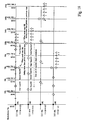
- Embodiment [1] in this figure when the normal interval is defined as 36 hours, since the interval is longer than one day (24 hours) by 12 hours (a half-day), it follows that at the end of the first interval 36 hours (one and a half days) later, the offset relative to the preceding operation time point is 12 hours, and at the end of the second check operation interval 72 hours (three days) later, the check operation time point returns to that at the start.
- control unit 75 When charging becomes possible or sufficient charging is achieved in the course of the check operations repeatedly conducted at short intervals before the prescribed number of check operations has been completed, the control unit 75 preferably restores the check operation to the normal interval (36 hours).
- Embodiment [2] in FIG. 18 when the normal interval is defined as 30 hours, since the interval is longer than one day (24 hours) by 6 hours (1/4 day), it follows that at the end of the second interval 60 hours (two and a half days) later, the offset relative to the preceding operation time point is 12 hours, and at the end of the fourth check operation interval 120 hours (five days) later, the check operation time point returns to that at the start.
- the control unit 75 judges that charging was impossible or insufficient during a prescribed number of consecutive intervals following the last time that charging was possible (the number of consecutive intervals is four in this embodiment but can be greater), the succeeding check operations are conducted at a shorter interval.
- the shorter interval is preferably 6 hours.
Claims (15)
- Eine Struktur zur Installation eines Diebstahlschutzgeräts, wobei die Struktur umfasst:- eine in einem Motorrad auszubildende Aufnahme (5);- einen in einem Motorrad auszubildenden Deckel (6) der geöffnet werden kann und der abgeschlossen werden kann, um die Aufnahme (5) zu sichern, und- ein in der Aufnahme (5) installiertes Diebstahlschutzgerät (20), dadurch gekennzeichnet, dass:- das Diebstahlschutzgerät (20) in der Lage ist, durch drahtloses Übertragen zumindest von identifizierender Information seine Position mitzuteilen; und durch- ein Gehäuse (30) in der Aufnahme zum Halten des Diebstahlschutzgeräts (20), welches zumindest aus einem Abschnitt gebildet wird, das an einer aus nicht vibrierendem Material hergestellten Motorradkörperseite zu befestigen ist und einen transparenten Bereich (50) besitzt, durch den hindurch ein Anzeiger des Diebstahlschutzgeräts (20) betrachtet werden kann.
- Eine Struktur gemäß Anspruch 1, bei der das Diebstahlschutzgerät (20) zwischen einer Wand der Aufnahme (5) und einer die Wand bedeckenden Auskleidungsschicht installiert ist.
- Eine Struktur gemäß Anspruch 1, bei der die Aufnahme (5) mit einer internen Aussparung ausgebildet ist, wobei das Diebstahlschutzgerät (20) in der Aussparung der Aufnahme (5) installiert ist und eine Öffnung der Aussparung mit einer Auskleidungsschicht bedeckt ist.
- Eine Struktur gemäß Anspruch 1, bei der das Diebstahlschutzgerät (20) an einer Seitenwand der Aufnahme (5) im wesentlichen in ihrer Mitte in Motorradlängserstreckungsrichtung befestigt ist.
- Eine Struktur gemäß Anspruch 1, wobei die Aufnahme (5) eine Box zum Aufnehmen von zwei Helmen ist und das Diebstahlschutzgerät (20) in einem Raum installiert ist, der zwischen den Räumen zur Aufnahme der Helme zur Verfügung steht.
- Eine Struktur gemäß einem der voranstehenden Ansprüche, bei der das Gehäuse (30) zum Halten des Diebstahlschutzgeräts (20) aus einem an der Motorradkörperseite zu befestigenden Halter (40) und einem an dem Halter (40) durch eine wasserdichte Struktur befestigbaren Deckel (50) aufgebaut ist, wobei zumindest ein Abschnitt des an der Motorradkörperseite zu befestigenden Halters (40) aus einem nicht vibrierenden Material besteht und der Deckel (50) einen transparenten Abschnitt besitzt, durch den hindurch ein Anzeiger des Diebstahlschutzgeräts (20) betrachtet werden kann.
- Eine Struktur gemäß einem der voranstehenden Ansprüche, bei der der Abschnitt des Gehäuses, der dem Motorradkörper zugewandt ist, mit einem Polstermaterial versehen ist.
- Eine Struktur gemäß einem der voranstehenden Ansprüche, wobei das Gehäuse (30) mit einem Eingriffselement (45) versehen ist und eine Schnur (26), welche das Diebstahlschutzgerät (20) und eine Bordbatterie (10) des Motorrads miteinander verbindet, aus dem Gehäuse (30) austritt, durch das Eingriffselement (45) geschlungen ist und zur Batterieseite weiterführt.
- Eine Struktur gemäß einem der voranstehenden Ansprüche, wobei das Gehäuse (30) ein zylindrisches Element (45) einschließlich eines Lochs umfasst, um es einer Schnur (26) zu ermöglichen, aus dem Gehäuse (30) auszutreten, wobei die Schnur (26) an dem Diebstahlschutzgerät (20) befestigt ist.
- Eine Struktur gemäß Anspruch 9, wobei das Diebstahlschutzgerät (20) eine interne Batterie (71) besitzt, die an ein Bordladegerät (27) mittels der Schnur (26), die durch einen Verbinder (25) mit dem Diebstahlschutzgerät (20) verbunden ist, angeschlossen ist, wobei das Bordladegerät (27) an eine Bordbatterie (10) anschließbar ist.
- Eine Struktur gemäß Anspruch 10, wobei die interne Batterie (21) über einen internen Wandler (73) an das Bordladegerät (27) angeschlossen ist.
- Eine Struktur gemäß Anspruch 11, wobei das Bordladegerät (27) mit einer Steuereinheit (75) und einem Schalter (74) zum Herstellen und Unterbrechen einer Verbindung zum Diebstahlschutzgerät (20) ausgerüstet ist.
- Eine Struktur gemäß einem der voranstehenden Ansprüche, wobei das Diebstahlschutzgerät (20) so angeordnet ist, dass es vor Sicht geschützt ist.
- Ein Motorrad einschließlich einer Struktur gemäß einem der voranstehenden Ansprüche.
- Ein Verfahren zum Installieren eines Diebstahlschutzgeräts (20) in einem Motorrad, welches in der Lage ist, durch drahtloses Übertragen zumindest von identifizierender Information seine Position mitzuteilen, wobei das Verfahren umfasst:- Ausbilden einer Struktur einschließlich einer Aufnahme (5) und eines Deckels, der geöffnet werden kann und der geschlossen werden kann, um die Aufnahme (5) zu sichern, in einem Motorrad;- Ausbilden eines Gehäuses (30) zum Halten des Diebstahlschutzgeräts (20), wobei das Gehäuse einen transparenten Abschnitt (50) zum Betrachten des Diebstahlschutzgeräts (20) besitzt; und- Installieren des in dem Gehäuse (30) gehaltenen Diebstahlschutzgeräts (20) in der Aufnahme (5).
Applications Claiming Priority (4)
| Application Number | Priority Date | Filing Date | Title |
|---|---|---|---|
| JP2001103082 | 2001-04-02 | ||
| JP2001103082 | 2001-04-02 | ||
| JP2002021277A JP4189154B2 (ja) | 2001-04-02 | 2002-01-30 | 自動二輪車の盗難対策装置設置構造 |
| JP2002021277 | 2002-01-30 |
Publications (3)
| Publication Number | Publication Date |
|---|---|
| EP1247706A2 EP1247706A2 (de) | 2002-10-09 |
| EP1247706A3 EP1247706A3 (de) | 2004-02-04 |
| EP1247706B1 true EP1247706B1 (de) | 2006-05-10 |
Family
ID=26612945
Family Applications (1)
| Application Number | Title | Priority Date | Filing Date |
|---|---|---|---|
| EP20020252239 Expired - Fee Related EP1247706B1 (de) | 2001-04-02 | 2002-03-27 | Anordnungsstruktur einer Diebstahlsicherung für Motorräder |
Country Status (5)
| Country | Link |
|---|---|
| US (1) | US7034665B2 (de) |
| EP (1) | EP1247706B1 (de) |
| JP (1) | JP4189154B2 (de) |
| DE (1) | DE60211245T2 (de) |
| ES (1) | ES2262757T3 (de) |
Families Citing this family (55)
| Publication number | Priority date | Publication date | Assignee | Title |
|---|---|---|---|---|
| FR2842493B1 (fr) * | 2002-07-18 | 2005-09-09 | De Meder Laurent Bourgine | Procede et dispositif de securite pour vehicule deux roues et similaires |
| JP4593465B2 (ja) | 2003-02-14 | 2010-12-08 | 本田技研工業株式会社 | Icタグ搭載のスクータ型自動二輪車 |
| JP4243162B2 (ja) * | 2003-10-15 | 2009-03-25 | 本田技研工業株式会社 | 軽車両 |
| US7252171B2 (en) * | 2003-11-12 | 2007-08-07 | Augustine Jr James J | Contoured rear fender storage container for a motorcycle |
| JP4184256B2 (ja) | 2003-12-25 | 2008-11-19 | 本田技研工業株式会社 | 商品管理システム |
| JP2005242659A (ja) * | 2004-02-26 | 2005-09-08 | Honda Motor Co Ltd | タグ取付方法及びタグ付金属部品 |
| JP4989539B2 (ja) * | 2008-03-28 | 2012-08-01 | 本田技研工業株式会社 | 車両の盗難防止装置 |
| JP2010120626A (ja) | 2008-10-24 | 2010-06-03 | Yamaha Motor Co Ltd | 自動二輪車 |
| JP2010120628A (ja) | 2008-10-24 | 2010-06-03 | Yamaha Motor Co Ltd | 自動二輪車 |
| JP2010120625A (ja) | 2008-10-24 | 2010-06-03 | Yamaha Motor Co Ltd | 自動二輪車 |
| JP2010120627A (ja) | 2008-10-24 | 2010-06-03 | Yamaha Motor Co Ltd | 自動二輪車 |
| JP5222693B2 (ja) * | 2008-10-31 | 2013-06-26 | 本田技研工業株式会社 | 自動二輪車 |
| JP5205217B2 (ja) * | 2008-11-04 | 2013-06-05 | 本田技研工業株式会社 | 自動二輪車の盗難対策装置 |
| JP5192995B2 (ja) * | 2008-11-14 | 2013-05-08 | 本田技研工業株式会社 | 自動二輪車の盗難対策装置 |
| JP5042984B2 (ja) * | 2008-12-26 | 2012-10-03 | 本田技研工業株式会社 | 自動二輪車 |
| EP2404792B1 (de) * | 2009-03-06 | 2013-12-25 | Honda Motor Co., Ltd. | Feststellung von abnormalitäten und fahrzeugortungsvorrichtung |
| JP5412199B2 (ja) * | 2009-07-17 | 2014-02-12 | 本田技研工業株式会社 | 自動二輪車 |
| JP5469945B2 (ja) * | 2009-07-17 | 2014-04-16 | 本田技研工業株式会社 | 自動二輪車 |
| JP5235176B2 (ja) * | 2009-07-31 | 2013-07-10 | 本田技研工業株式会社 | 自動二輪車 |
| JP5235177B2 (ja) * | 2009-07-31 | 2013-07-10 | 本田技研工業株式会社 | 自動二輪車 |
| JP5287587B2 (ja) * | 2009-08-07 | 2013-09-11 | 本田技研工業株式会社 | 盗難防止装置及び盗難防止方法 |
| JP5486966B2 (ja) * | 2010-03-10 | 2014-05-07 | 本田技研工業株式会社 | 鞍乗り型車両 |
| JP5470104B2 (ja) * | 2010-03-10 | 2014-04-16 | 本田技研工業株式会社 | 鞍乗り型車両 |
| JP2012025297A (ja) | 2010-07-26 | 2012-02-09 | Yamaha Motor Co Ltd | 自動二輪車、及び、自動二輪車に搭載される盗難通報装置 |
| JP5520733B2 (ja) * | 2010-07-28 | 2014-06-11 | 本田技研工業株式会社 | 鞍乗り型車両 |
| JP5558981B2 (ja) * | 2010-09-13 | 2014-07-23 | 株式会社東海理化電機製作所 | 車両用通信システム |
| CN103619698B (zh) * | 2011-06-23 | 2016-10-05 | 本田技研工业株式会社 | 电子装置用防水构造 |
| WO2012176299A1 (ja) * | 2011-06-23 | 2012-12-27 | 本田技研工業株式会社 | 車両盗難防止装置 |
| IN2014CN00497A (de) * | 2011-06-23 | 2015-04-03 | Honda Motor Co Ltd | |
| JP5782932B2 (ja) * | 2011-09-05 | 2015-09-24 | スズキ株式会社 | 自動二輪車 |
| JP5358654B2 (ja) * | 2011-11-21 | 2013-12-04 | 本田技研工業株式会社 | 自動二輪車 |
| JP5536751B2 (ja) * | 2011-12-20 | 2014-07-02 | 本田技研工業株式会社 | 自動2輪車の盗難対策装置配置構造 |
| EP2615002B1 (de) * | 2012-01-13 | 2014-04-30 | Denso Corporation | Diebstahlverfolgungsvorrichtung |
| JP5882803B2 (ja) * | 2012-03-22 | 2016-03-09 | 本田技研工業株式会社 | 鞍乗り型車両 |
| JP5656923B2 (ja) * | 2012-06-18 | 2015-01-21 | 本田技研工業株式会社 | 自動二輪車の盗難対策装置 |
| JP5656924B2 (ja) * | 2012-06-18 | 2015-01-21 | 本田技研工業株式会社 | 自動二輪車の盗難対策装置 |
| JP5492948B2 (ja) * | 2012-07-11 | 2014-05-14 | 本田技研工業株式会社 | 自動二輪車 |
| CN103048665A (zh) * | 2012-11-26 | 2013-04-17 | 精功镇江汽车制造有限公司 | 纯电动汽车的蓄电池gps定位系统 |
| JP5487334B2 (ja) * | 2013-01-21 | 2014-05-07 | 本田技研工業株式会社 | 自動二輪車の盗難対策装置 |
| JP5487335B2 (ja) * | 2013-01-21 | 2014-05-07 | 本田技研工業株式会社 | 自動二輪車の盗難対策装置 |
| JP6083600B2 (ja) * | 2013-01-31 | 2017-02-22 | 本田技研工業株式会社 | 鞍乗り型車両における通信ユニットの配置構造 |
| USD746760S1 (en) | 2014-08-15 | 2016-01-05 | Technologies Bewegen Inc. | Bicycle basket |
| USD730780S1 (en) | 2014-08-15 | 2015-06-02 | Technologies Bewegen Inc. | Bicycle |
| USD766138S1 (en) | 2014-08-15 | 2016-09-13 | Technologies Bewegen Inc. | Base station for a bicycle sharing system |
| USD730779S1 (en) | 2014-08-15 | 2015-06-02 | Technologies Bewegen Inc. | Electric bicycle |
| USD738276S1 (en) | 2014-08-18 | 2015-09-08 | Technologies Bewegen Inc. | Bicycle handlebar |
| USD776576S1 (en) | 2014-08-18 | 2017-01-17 | Technologies Bewegen Inc. | Electric bicycle |
| USD730781S1 (en) | 2014-08-18 | 2015-06-02 | Technologies Bewegen Inc. | Electric bicycle |
| US9786153B2 (en) | 2014-11-26 | 2017-10-10 | Justin London | Multi-modal tracking locator alarm system |
| JP2018090175A (ja) * | 2016-12-06 | 2018-06-14 | ヤマハ発動機株式会社 | 鞍乗型車両および鞍乗型車両への追跡装置の取付方法 |
| US11753101B2 (en) | 2018-04-27 | 2023-09-12 | FUELL Inc. | Electric saddle type vehicle with storage areas |
| US11299229B2 (en) | 2018-04-27 | 2022-04-12 | FUELL Inc. | Electric saddle type vehicle chassis |
| US11654996B2 (en) | 2018-04-27 | 2023-05-23 | FUELL Inc. | Electric saddle type vehicle |
| WO2020150646A1 (en) * | 2019-01-17 | 2020-07-23 | FUELL Inc. | Electric saddle type vehicle with storage areas |
| CN115497245B (zh) * | 2022-11-16 | 2023-03-10 | 合肥松果智造智能科技有限公司 | 防盗监管方法、装置、计算机设备和存储介质 |
Family Cites Families (14)
| Publication number | Priority date | Publication date | Assignee | Title |
|---|---|---|---|---|
| US4322714A (en) * | 1980-11-17 | 1982-03-30 | Martek Products, Inc. | Vehicle anti-theft alarm |
| US4641124A (en) * | 1982-09-13 | 1987-02-03 | Davis Dwin S | Vehicle security alarm |
| JPS6130450A (ja) | 1984-07-20 | 1986-02-12 | Yamaha Motor Co Ltd | 車両用盗難防止装置 |
| JP2665478B2 (ja) | 1987-02-13 | 1997-10-22 | 本田技研工業株式会社 | 車輌盗難対策装置 |
| DE3839959A1 (de) * | 1988-10-06 | 1990-04-12 | Bosch Gmbh Robert | Notrufeinrichtung fuer ein fahrzeug |
| US5147077A (en) * | 1990-01-25 | 1992-09-15 | Suzuki Kabushiki Kaisha | Storage box compartment means for a motorcycle |
| US5629693A (en) * | 1993-11-24 | 1997-05-13 | Trimble Navigation Limited | Clandestine location reporting by a missing vehicle |
| US5534847A (en) * | 1994-11-23 | 1996-07-09 | Mcgregor; Gerald C. | Bicycle alarm system |
| AU8559498A (en) * | 1997-08-20 | 1999-03-08 | Locus Corporation | Positioning system and mobile communication device |
| US5894810A (en) * | 1998-04-22 | 1999-04-20 | Orr; John D. | Personal watercraft having a hood assembly with a base piece for mounting a stereo system |
| US6459426B1 (en) * | 1998-08-17 | 2002-10-01 | Genesis Microchip (Delaware) Inc. | Monolithic integrated circuit implemented in a digital display unit for generating digital data elements from an analog display signal received at high frequencies |
| US6028507A (en) * | 1999-03-30 | 2000-02-22 | John Banks | Security system for motor vehicles |
| JP2001009071A (ja) | 1999-06-25 | 2001-01-16 | Mizuno Corp | アイアンゴルフクラブヘッド、アイアンゴルフクラブ及びアイアンゴルフクラブセット |
| JP2001196529A (ja) | 2000-01-17 | 2001-07-19 | Mitsubishi Electric Corp | 半導体装置及びその配線方法 |
-
2002
- 2002-01-30 JP JP2002021277A patent/JP4189154B2/ja not_active Expired - Fee Related
- 2002-03-27 EP EP20020252239 patent/EP1247706B1/de not_active Expired - Fee Related
- 2002-03-27 ES ES02252239T patent/ES2262757T3/es not_active Expired - Lifetime
- 2002-03-27 DE DE2002611245 patent/DE60211245T2/de not_active Expired - Lifetime
- 2002-05-21 US US10/112,489 patent/US7034665B2/en not_active Expired - Fee Related
Also Published As
| Publication number | Publication date |
|---|---|
| US20040036609A1 (en) | 2004-02-26 |
| JP2002362448A (ja) | 2002-12-18 |
| ES2262757T3 (es) | 2006-12-01 |
| DE60211245D1 (de) | 2006-06-14 |
| EP1247706A2 (de) | 2002-10-09 |
| EP1247706A3 (de) | 2004-02-04 |
| JP4189154B2 (ja) | 2008-12-03 |
| DE60211245T2 (de) | 2007-03-08 |
| US7034665B2 (en) | 2006-04-25 |
Similar Documents
| Publication | Publication Date | Title |
|---|---|---|
| EP1247706B1 (de) | Anordnungsstruktur einer Diebstahlsicherung für Motorräder | |
| US20020113491A1 (en) | Anti-theft device installation structure for motorcycle | |
| US5552642A (en) | Protection system with voltage switching | |
| US20150318521A1 (en) | Rechargeable battery system for replacement of lead-acid battery | |
| WO2008058222A2 (en) | Power management systems for automotive video event recorders | |
| JPH07293079A (ja) | 車両用携帯式電装装置 | |
| US20040239502A1 (en) | Storage battery loaded onto vehicle | |
| CN1261472A (zh) | 用于在具有电池的车辆中使用的电子附件的电池放电保护系统 | |
| US20090147427A1 (en) | Battery disconnect device | |
| CN101312292A (zh) | 电源管理装置 | |
| CN204915915U (zh) | 一种电动车锂电池遥控智能防盗系统 | |
| CN113212609A (zh) | 一种车辆智能警报方法、系统及电动车 | |
| CN103958294A (zh) | 保安系统 | |
| US10513188B2 (en) | Rechargeable battery pack for electric or hybrid vehicles comprising a communication interface | |
| JP2003112606A (ja) | 盗難防止装置 | |
| KR101088499B1 (ko) | 지중전력설비함체용 보안키시스템 및 그 보안키 | |
| US20170313194A1 (en) | Rechargeable battery pack for electric or hybrid vehicles | |
| MXPA06001615A (es) | Sistema de bateria multiple, sistema de manejo de bateria multiple, sistema de fijacion de la bateria auxiliar y sistema de bateria multiple controlado por red. | |
| US6707377B2 (en) | Remote control apparatus and method | |
| CN112550221A (zh) | 一种基于光能发电的汽车防盗装置 | |
| CN101812946B (zh) | 一种防盗摄像锁 | |
| CN201240351Y (zh) | 带独立电源的汽车防盗报警器 | |
| CN103373319A (zh) | 车用监控装置及其电源管理模块 | |
| CN217396712U (zh) | 一种智能报警锁 | |
| CN215245232U (zh) | 一种车辆智能警报系统及电动车 |
Legal Events
| Date | Code | Title | Description |
|---|---|---|---|
| PUAI | Public reference made under article 153(3) epc to a published international application that has entered the european phase |
Free format text: ORIGINAL CODE: 0009012 |
|
| AK | Designated contracting states |
Kind code of ref document: A2 Designated state(s): AT BE CH CY DE DK ES FI FR GB GR IE IT LI LU MC NL PT SE TR |
|
| AX | Request for extension of the european patent |
Free format text: AL;LT;LV;MK;RO;SI |
|
| PUAL | Search report despatched |
Free format text: ORIGINAL CODE: 0009013 |
|
| AK | Designated contracting states |
Kind code of ref document: A3 Designated state(s): AT BE CH CY DE DK ES FI FR GB GR IE IT LI LU MC NL PT SE TR |
|
| AX | Request for extension of the european patent |
Extension state: AL LT LV MK RO SI |
|
| RIC1 | Information provided on ipc code assigned before grant |
Ipc: 7B 60R 25/10 A Ipc: 7B 60R 11/00 B |
|
| 17P | Request for examination filed |
Effective date: 20040301 |
|
| 17Q | First examination report despatched |
Effective date: 20040427 |
|
| AKX | Designation fees paid |
Designated state(s): DE ES FR GB IT |
|
| GRAP | Despatch of communication of intention to grant a patent |
Free format text: ORIGINAL CODE: EPIDOSNIGR1 |
|
| GRAS | Grant fee paid |
Free format text: ORIGINAL CODE: EPIDOSNIGR3 |
|
| GRAA | (expected) grant |
Free format text: ORIGINAL CODE: 0009210 |
|
| AK | Designated contracting states |
Kind code of ref document: B1 Designated state(s): DE ES FR GB IT |
|
| PG25 | Lapsed in a contracting state [announced via postgrant information from national office to epo] |
Ref country code: IT Free format text: LAPSE BECAUSE OF FAILURE TO SUBMIT A TRANSLATION OF THE DESCRIPTION OR TO PAY THE FEE WITHIN THE PRESCRIBED TIME-LIMIT;WARNING: LAPSES OF ITALIAN PATENTS WITH EFFECTIVE DATE BEFORE 2007 MAY HAVE OCCURRED AT ANY TIME BEFORE 2007. THE CORRECT EFFECTIVE DATE MAY BE DIFFERENT FROM THE ONE RECORDED. Effective date: 20060510 |
|
| REG | Reference to a national code |
Ref country code: GB Ref legal event code: FG4D |
|
| REF | Corresponds to: |
Ref document number: 60211245 Country of ref document: DE Date of ref document: 20060614 Kind code of ref document: P |
|
| ET | Fr: translation filed | ||
| REG | Reference to a national code |
Ref country code: ES Ref legal event code: FG2A Ref document number: 2262757 Country of ref document: ES Kind code of ref document: T3 |
|
| PLBE | No opposition filed within time limit |
Free format text: ORIGINAL CODE: 0009261 |
|
| STAA | Information on the status of an ep patent application or granted ep patent |
Free format text: STATUS: NO OPPOSITION FILED WITHIN TIME LIMIT |
|
| 26N | No opposition filed |
Effective date: 20070213 |
|
| REG | Reference to a national code |
Ref country code: GB Ref legal event code: 732E Free format text: REGISTERED BETWEEN 20100304 AND 20100310 |
|
| REG | Reference to a national code |
Ref country code: ES Ref legal event code: PC2A |
|
| REG | Reference to a national code |
Ref country code: FR Ref legal event code: TP |
|
| REG | Reference to a national code |
Ref country code: GB Ref legal event code: 746 Effective date: 20111128 |
|
| REG | Reference to a national code |
Ref country code: DE Ref legal event code: R082 Ref document number: 60211245 Country of ref document: DE Representative=s name: KLUNKER, SCHMITT-NILSON, HIRSCH, DE Effective date: 20120503 Ref country code: DE Ref legal event code: R081 Ref document number: 60211245 Country of ref document: DE Owner name: HONDA GIKEN KOGYO K.K., JP Free format text: FORMER OWNERS: HONDA GIKEN KOGYO K.K., TOKYO, JP; HONDA ACCESS CORP., NIIZA, SAITAMA, JP Effective date: 20120503 Ref country code: DE Ref legal event code: R081 Ref document number: 60211245 Country of ref document: DE Owner name: HONDA GIKEN KOGYO K.K., JP Free format text: FORMER OWNER: HONDA GIKEN KOGYO K.K., HONDA ACCESS CORP., , JP Effective date: 20120503 |
|
| PGFP | Annual fee paid to national office [announced via postgrant information from national office to epo] |
Ref country code: IT Payment date: 20120321 Year of fee payment: 11 |
|
| PGFP | Annual fee paid to national office [announced via postgrant information from national office to epo] |
Ref country code: DE Payment date: 20130320 Year of fee payment: 12 |
|
| PGFP | Annual fee paid to national office [announced via postgrant information from national office to epo] |
Ref country code: FR Payment date: 20140311 Year of fee payment: 13 Ref country code: ES Payment date: 20140211 Year of fee payment: 13 |
|
| REG | Reference to a national code |
Ref country code: DE Ref legal event code: R119 Ref document number: 60211245 Country of ref document: DE |
|
| REG | Reference to a national code |
Ref country code: DE Ref legal event code: R119 Ref document number: 60211245 Country of ref document: DE Effective date: 20141001 |
|
| PG25 | Lapsed in a contracting state [announced via postgrant information from national office to epo] |
Ref country code: DE Free format text: LAPSE BECAUSE OF NON-PAYMENT OF DUE FEES Effective date: 20141001 |
|
| PG25 | Lapsed in a contracting state [announced via postgrant information from national office to epo] |
Ref country code: IT Free format text: LAPSE BECAUSE OF NON-PAYMENT OF DUE FEES Effective date: 20140327 |
|
| PGFP | Annual fee paid to national office [announced via postgrant information from national office to epo] |
Ref country code: GB Payment date: 20150325 Year of fee payment: 14 |
|
| REG | Reference to a national code |
Ref country code: FR Ref legal event code: ST Effective date: 20151130 |
|
| PG25 | Lapsed in a contracting state [announced via postgrant information from national office to epo] |
Ref country code: FR Free format text: LAPSE BECAUSE OF NON-PAYMENT OF DUE FEES Effective date: 20150331 |
|
| REG | Reference to a national code |
Ref country code: ES Ref legal event code: FD2A Effective date: 20160426 |
|
| PG25 | Lapsed in a contracting state [announced via postgrant information from national office to epo] |
Ref country code: ES Free format text: LAPSE BECAUSE OF NON-PAYMENT OF DUE FEES Effective date: 20150328 |
|
| GBPC | Gb: european patent ceased through non-payment of renewal fee |
Effective date: 20160327 |
|
| PG25 | Lapsed in a contracting state [announced via postgrant information from national office to epo] |
Ref country code: GB Free format text: LAPSE BECAUSE OF NON-PAYMENT OF DUE FEES Effective date: 20160327 |