EP1233915B1 - Standbeutel mit umknickbarem verschlusselement - Google Patents
Standbeutel mit umknickbarem verschlusselement Download PDFInfo
- Publication number
- EP1233915B1 EP1233915B1 EP00972827A EP00972827A EP1233915B1 EP 1233915 B1 EP1233915 B1 EP 1233915B1 EP 00972827 A EP00972827 A EP 00972827A EP 00972827 A EP00972827 A EP 00972827A EP 1233915 B1 EP1233915 B1 EP 1233915B1
- Authority
- EP
- European Patent Office
- Prior art keywords
- stand
- side wall
- closure element
- pouch
- embossing
- Prior art date
- Legal status (The legal status is an assumption and is not a legal conclusion. Google has not performed a legal analysis and makes no representation as to the accuracy of the status listed.)
- Expired - Lifetime
Links
Images


Classifications
-
- B—PERFORMING OPERATIONS; TRANSPORTING
- B65—CONVEYING; PACKING; STORING; HANDLING THIN OR FILAMENTARY MATERIAL
- B65D—CONTAINERS FOR STORAGE OR TRANSPORT OF ARTICLES OR MATERIALS, e.g. BAGS, BARRELS, BOTTLES, BOXES, CANS, CARTONS, CRATES, DRUMS, JARS, TANKS, HOPPERS, FORWARDING CONTAINERS; ACCESSORIES, CLOSURES, OR FITTINGS THEREFOR; PACKAGING ELEMENTS; PACKAGES
- B65D75/00—Packages comprising articles or materials partially or wholly enclosed in strips, sheets, blanks, tubes, or webs of flexible sheet material, e.g. in folded wrappers
- B65D75/52—Details
- B65D75/58—Opening or contents-removing devices added or incorporated during package manufacture
- B65D75/5861—Spouts
- B65D75/5872—Non-integral spouts
- B65D75/5883—Non-integral spouts connected to the package at the sealed junction of two package walls
-
- B—PERFORMING OPERATIONS; TRANSPORTING
- B65—CONVEYING; PACKING; STORING; HANDLING THIN OR FILAMENTARY MATERIAL
- B65D—CONTAINERS FOR STORAGE OR TRANSPORT OF ARTICLES OR MATERIALS, e.g. BAGS, BARRELS, BOTTLES, BOXES, CANS, CARTONS, CRATES, DRUMS, JARS, TANKS, HOPPERS, FORWARDING CONTAINERS; ACCESSORIES, CLOSURES, OR FITTINGS THEREFOR; PACKAGING ELEMENTS; PACKAGES
- B65D75/00—Packages comprising articles or materials partially or wholly enclosed in strips, sheets, blanks, tubes, or webs of flexible sheet material, e.g. in folded wrappers
- B65D75/008—Standing pouches, i.e. "Standbeutel"
-
- Y—GENERAL TAGGING OF NEW TECHNOLOGICAL DEVELOPMENTS; GENERAL TAGGING OF CROSS-SECTIONAL TECHNOLOGIES SPANNING OVER SEVERAL SECTIONS OF THE IPC; TECHNICAL SUBJECTS COVERED BY FORMER USPC CROSS-REFERENCE ART COLLECTIONS [XRACs] AND DIGESTS
- Y10—TECHNICAL SUBJECTS COVERED BY FORMER USPC
- Y10S—TECHNICAL SUBJECTS COVERED BY FORMER USPC CROSS-REFERENCE ART COLLECTIONS [XRACs] AND DIGESTS
- Y10S383/00—Flexible bags
- Y10S383/906—Dispensing feature
Definitions
- the invention relates to a stand-up pouch made of a heat sealable or weldable Plastic film for holding liquid and / or pasty material, with two side walls, which are connected to each other at their longitudinal edges, being at the bottom Stand-up pouch end between the lower transverse edges a foldable, between the side walls lying, serving as a standing floor part is arranged and at the top Stand-up pouch end between the side walls is a foldable ceiling part, and with a removal opening between the upper transverse edge of a first side wall and the associated edge of the ceiling part, a closure element in the removal opening is used.
- FIG. Stand-up pouch already known comprises two side walls, one serving as a stand-up base Floor part and a ceiling part.
- the floor and ceiling part comes in connected State of the bag to lie within the contour of the side walls. Fold these parts accordingly when filling the container.
- To create the pouch the parts shown in Fig. 14 welded together.
- the long edges the side walls sealed along the areas shown in dashed lines.
- the corner areas the side walls are covered with areas of the corresponding floor or ceiling part connected flat or linear in the manner of a triangle. Even the dashed ones Cross edges of the side walls are with the corresponding cross edges of the ceiling and Bottom part connected. Between a side wall and the corresponding cover part a removal opening is formed.
- a closure element is in this removal opening used.
- the pouring of the contents from the stand-up pouch can, however occasionally due to the more or less rigidly projecting closure element prove to be difficult since the entire pouch will be tilted down sharply got to. Especially with very full stand-up pouches it can spill Liquid come.
- the present invention is therefore based on the object of the known stand-up pouch in terms of handling, especially when pouring.
- this object is achieved in that the stand-up pouch in the first Sidewall in a region below the closure element a means for stabilizing and holding the fastener in a forward bent position comprises, wherein the means is formed from at least one embossing.
- the stand-up pouch according to the invention enables the closure element to move forward can be folded and remains stable in this position.
- the overturned The closure element remains in its position even when the stand-up pouch is closed Pouring in hand and squeezing it. In the overturned Position can hold liquid through the closure element even at very full Bags can be poured out safely and easily without the bag being very strongly inclined must become.
- the upper one Ceiling part in a region below the closure element means for stabilizing and holding the closure member in an upright position at least one embossing is formed.
- the means for stabilizing and holding consist of at least a linear embossing, e.g. from two sides to the middle Longitudinal axis of the first side wall extends.
- the embossing can, for example run semi-oval or triangular.
- Such imprints form one Bending limit within which the closure element bends forwards the area between the embossments and the closure element inwards bulges the bag.
- the embossing is advantageously arranged in the upper third of the first side wall. This leads to the desired stabilization.
- the ceiling part is over sealing seams from both longitudinal edges obliquely to the removal opening of the first side wall or extend obliquely to the upper transverse edge of the second side wall, with the respective Side wall connected, the beveled sealing seams the same Outside seams are.
- the beveled in this embodiment Sealing seams that extend from both ends of the longitudinal edges to the removal opening or upper transverse edge, the ceiling part is no longer through the longitudinal seam restricted and can fold out well when the bulge is filled.
- the removal opening is between one formed on a side wall, across the transverse edge the side wall protruding side wall tab and a corresponding on Cover part formed formed part of the cover plate, which along their longitudinal edges with each other are connected.
- the removal opening is from limited two tabs into which the closure element is inserted. Such an arrangement enables an even better kinking of the closure element.
- the side walls are spaced apart between the transverse edges running outward longitudinal embossments are provided.
- These longitudinal embossings form longitudinal fold lines, which are in the form of depressions in the film material be impressed.
- the length of the first side wall is greater than the length of the second side wall, so that the removal opening of the first side wall to lie above the upper transverse edge of the second side wall comes.
- the removal opening protrudes above the edge of the bag, so that the closure elements, e.g. a screw cap, simplified into the removal opening can be welded.
- the ceiling part is formed in one piece with the second side wall is. Because the ceiling part is not specially welded to the top edge of the side wall this shape saves a welding step. In addition, can bulge the ceiling part rounder and smoother in this area, as there are no protruding parts Weld seam is annoying. This is particularly advantageous if the closure element is bent towards vome, with the entire ceiling part stretching towards vome.
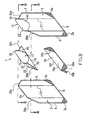
- the individual components of the stand-up pouch according to the invention a first embodiment. These parts are preferably made of film material formed in a dual network in a manner known per se.
- the stand-up pouch comprises a side wall 2, a side wall 3 base part 10 serving as standing floor and a ceiling part 11.
- the bottom and top part comes within the connected state of the bag Contour of the side walls to lie. These parts fold when the container is filled then accordingly.
- a ceiling panel flap 15 is integral with the side wall educated.
- the side wall flap is also integral with the side wall 2 14 designed and corresponding to the ceiling part tab 15.
- the individual Parts are now connected to each other to create the bag.
- the corner areas 3a, 3b, 3c and 3d of the side wall 3 with the corner areas 11a, 11b, 10b and in the drawing not shown rear corner of the bottom part flat in the manner of a triangle connected.
- corner areas 11d, 11c, 10a and 10c are in accordance with this order the corner areas 2d, 2c, 2b and 2a of the side wall 2 are also triangular welded.
- edges of the floor and ceiling sections pointing to the side are covered with the Longitudinal edges 4 and 6 or 5 and 7 also welded lengthways.
- the lower edge 8 is connected to the edge of the base part assigned to it, while the lower edge of the base part 10 facing the side wall 2 is welded to the lower edge 9 of this side wall.
- the ceiling part is over the length of its upper side facing the side wall 3 Edge welded to the corresponding upper edge of the side wall.
- the ceiling panel 15, however, is only along its longitudinal edge 16 and 18 with the corresponding Longitudinal edges 17 and 19 of the side wall bracket 14 welded.
- the side walls 2 and 3 are also with spaced, provided outward longitudinal embossments 21, as in Fig. 5 also is recognizable.
- the stand-up pouch according to the invention also means 33 for stabilizing and holding the bent forward Closure element 20 on.
- the device for stabilizing and holding is here the line embossing 33 is formed, which is located in an area below the Closure element 20 extends.
- the embossing 33 is approximately in this embodiment semi-oval directed from the inside to the outside. Between the embossing 33 and the Closure element 20 creates an area 40 which, as will be explained further below will buckle inwards when the locking area is bent.
- FIGS. 6 and 7 show a side view of the stand-up pouch shown in FIG is filled. Because the bag is filled, it bulges, as through regions 35 is shown to the outside. 6, the closure element 20 is in an upright position Position shown. Fig. 6 also clearly shows the embossing 33 and the area 40 between embossing 33 and closure element 20. Will now for better pouring the closure element 20 in the direction of arrow D e.g. Bent 90 ° downwards, as in Fig. 7 is shown, the areas 40 can put inside the bag, as is shown by the dashed lines. The curvature within the embossing 33 stabilizes and holds the bent closure element in position.
- Cover part also be provided with an embossing 34, as can be seen in FIG. 1 can.
- This embossment 34 runs below the in the welded state inserted closure element 20 and also extends in this case semi-oval to the folded edge 11 of the cover part 11.
- the embossing 34 is also from the inside directed outwards.
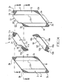
- This Bag differs from the bag shown in Fig. 1 in that the cover part via sealing seams 30 which extend obliquely from both ends of the longitudinal edges 4, 7 the removal opening 12 of the first side wall 2 or obliquely to the transverse edge 31 of the extend second side wall 3, is connected to the respective side wall 3, 2.
- the upper transverse edge 22 is with the upper transverse edge 31 of the side wall welded.
- the ceiling part tab 15 against it is only along its longitudinal edges 16, 18 with the corresponding longitudinal edges 17th and 19 of the side wall bracket 14 welded.
- a closure element 20 e.g. a screw closure element that is welded in.
- the longitudinal edges 4, 7 only extend to one point P, which is at the same height as the middle folded edge 11f of the ceiling part 11. Of this Point P out runs two sealing seams on each side of the stand-up pouch 30 to the removal opening 12 or to the upper transverse edge 31 of the respective side walls 2, 3. Because the longitudinal seams 4, 7 do not extend over the entire length h1 extend to the removal opening 12, the sealing seams 30, the outer seams represent, with a filled bag, as shown for example in Fig. 10a is free to move apart and thus form a V-shaped cutout 32. So is good unfolding of the ceiling part and also good handling of the bag guaranteed.
- a device 33 for stabilizing and Keep the locking element bent forward Like the first one Embodiment 33 extends in an area below the Closure element semi-oval.
- the embossing is directed from the inside to the outside. Between the closure element 20 and the embossment 33, the area 40, such as is clear from Figures 9 and 10a.
- the bag according to the invention can, as from the filled bag shown in Fig. 10a, have a ceiling part 11, the also has an embossment 34 which extends from the closure element 20 in the direction the middle folded edge 11f of the ceiling part 11 extends.
- FIGS. 11a and 11b essentially corresponds to that in FIGS 10a and 10b shown bags with the difference that the length h1 of the first Side wall 2 is greater than the length h2 of the second side wall 3, so that the removal opening 12 of the first side wall above the upper transverse edge 31 of the second Side wall 3 comes to rest.
- the bags shown in Figures 8-11 can also without embossing or means formed for stabilization 33, 34 on the first side wall and the ceiling part his.
- the ceiling part 11 which is between the side walls 2nd and 3 is inserted, are not welded to the upper edge 31 of the side wall 3, but can also be formed in one piece with the side wall 3. Because that Ceiling part does not have to be welded to the upper edge of the side wall, this shape saves a weld. In addition, the ceiling part can be in this Bulge the area rounder and smoother, since there is no protruding weld seam.
- FIG. 13a to d show different embodiments of the device for stabilization and hold. All facilities have in common that they are below the closure element 20 from two sides to the central longitudinal axis A of the first side wall 3 extend out.
- the embossing 33 is triangular. She runs essentially from both side edges of the closure element from triangular downward.
- 13b shows two embossments 33, which are below the closure element 20 run towards the central longitudinal axis A.
- Fig. 13c shows an embossing, which for Longitudinal axis A axisymmetric, first vertically, then obliquely and then horizontally runs.
- 13d shows two semi-oval embossments 33 lying one inside the other.
- the embossments do not have to reach the top of the bag or run up to the closure element 20 itself and they do not have to be exact either complete the side edges of the fastener. However, it is essential that they are in an area below the closure element 20 approximately in the upper third of the bag run.
- the embossments 34 on the ceiling part can have the same shapes as those in FIG Figure 13 have shapes shown. They then extend z. B. from two sides from towards the middle of the ceiling part in the direction of the folded edge 11f.
Description
- Fig. 1
- die Bestandteile eines erfindungsgemäßen Standbeutels in perspektivischer Ex plosionsdarstellung gemäß einem ersten Ausführungsbeispiel,
- Fig. 2
- eine Vorderansicht des erfindungsgemäßen Standbeutels aus Fig. 1,
- Fig. 3
- eine Ansicht auf den entlang der Linie III-III der Fig. 1 längs geschnittenen Stand beutel,
- Fig. 4
- eine Seitenansicht auf den entlang der Linie IV-IV der Fig. 1 längs geschnittenen Standbeutel,
- Fig. 5
- eine Draufsicht auf einen entlang der Linie V-V horizontal geschnittenen Behälter in der Form, wie er sie in gefülltem Zustand einnimmt,
- Fig. 6
- eine schematische Seitenansicht des in Fig. 2 gezeigten gefüllten Beutels mit aufrechtem Verschlußelement,
- Fig. 7
- den in Fig. 6 dargestellten gefüllten Standbeutel mit abgeknicktem Verschluße lement,
- Fig. 8
- die Bestandteile eines erfindungsgemäßen Standbeutels in perspektivischer Ex plosionsdarstellung, gemäß einem zweiten Ausführungsbeispiel,
- Fig. 9
- die Vorderansicht des in Fig. 8 gezeigten Standbeutels,
- Fig. 10a
- eine schematische Seitenansicht des in Fig. 9 gezeigten gefüllten Beutels,
- Fig. 10b
- den in Fig. 10a gezeigten Standbeutel mit abgeknicktem Verschlußele ment,
- Fig. 11a
- eine schematische Seitenansicht eines gefüllten Standbeutels, gemäß ei nem weiteren Ausführungsbeispiel der vorliegenden Erfindung,
- Fig. 11b
- den in Fig. 11a gezeigten Standbeutel mit abgeknicktem Verschlußele ment,
- Fig. 12
- eine zweite Standbeutelseitenwand, die einstückig mit dem Deckenteil ausgebildet ist,
- Figuren 13a bis e
- verschiedene Ausführungsformen der Einrichtung zum Stabilisieren und Halten des umgeknickten Verschlußelements,
- Figur 14
- einen aus dem Stand der Technik bekannten Standbeutel.
Claims (12)
- Standbeutel aus einer heißsiegelfähigen oder schweißbaren Kunststofffolie zur Aufnahme von flüssigem und/oder pastösem Gut, mit zwei Seitenwänden (2,3), die an ihren Längskanten miteinander verbunden sind, wobei am unteren Standbeutelende zwischen den unteren Querkanten (8, 9) ein faltbares, zwischen den Seitenwänden (2, 3) liegendes, als Standboden (10) dienendes Bodenteil angeordnet ist und am oberen Standbeutelende zwischen den Seitenwänden (2, 3) ein faltbares Deckenteil liegt, und mit einer Entnahmeöffnung (12) zwischen der oberen Querkante (13, 20) einer ersten Seitenwand (2) und der zugeordneten Deckenteilkante (21, 22), wobei in die Entnahmeöffnung (12) ein Verschlußelement (20) eingesetzt ist,
dadurch gekennzeichnet, dass
der Standbeutel in der ersten Seitenwand (2) in einem Bereich unterhalb des Verschlusselements (20) ein Mittel (33) zum Stabilisieren und Halten des Verschlusselements (20) in einer nach vom umgekippten Position umfasst, wobei das Mittel zum Stabilisieren und Halten des Verschlusselements aus mindestens einer Prägung (33, 34) gebildet ist. - Standbeutel nach Anspruch 1,
dadurch gekennzeichnet, dass
das obere Deckenteil in einem Bereich unterhalb des Verschlusselements (20) ein Mittel (34) zum Stabilisieren und Halten des Verschlusselements in einer aufrechten Position umfasst, wobei das Mittel zum Stabilisieren und Halten des Verschlusselements aus mindestens einer Prägung (33, 34) gebildet ist. - Standbeutel nach Anspruch 1,
dadurch gekennzeichnet, dass
sich die Prägung von zwei Seiten aus zur mittleren Längsachse (A) der ersten Seitenwand (2) hin als Linienprägung erstreckt. - Standbeutel nach mindestens einem der vorhergehenden Ansprüche,
dadurch gekennzeichnet, dass
die Prägung (33) eine halbovalförmige Linienprägung ist. - Standbeutel nach mindestens einem der vorhergehenden Ansprüche,
dadurch gekennzeichnet, dass die Prägung (33) eine dreiecksförmige Linienprägung ist. - Standbeutel nach mindestens einem der vorhergehenden Ansprüche,
dadurch gekennzeichnet, dass die Prägung (33, 34) von innen nach außen gerichtet ist. - Standbeutel nach mindestens einem der vorhergehenden Ansprüche,
dadurch gekennzeichnet, dass
die Mittel zum Stabilisieren und Halten des Verschlusselementes in der nach vorne umgekippten Position im oberen Drittel der ersten Seitenwand (2) angeordnet sind. - Standbeutel nach Anspruch 1,
dadurch gekennzeichnet, dass
die Entnahmeöffnung (12) zwischen einer an einer Seitenwand (2) ausgebildeten, über eine Querkante (13) der Seitenwand (2) vorstehenden Seitenwandlasche (14) und einer dazu korrespondierend am Deckenteil (11) ausgebildeten Deckenteillasche (15) gebildet ist, die entlang ihrer Längskanten (16, 17, 18, 19) miteinander verbunden sind. - Standbeutel insbesondere nach Anspruch 1 oder 8,
dadurch gekennzeichnet, dass
das Deckenteil (11) über Siegelnähte (30), die sich von beiden Längskanten (4, 7) aus schräg zu der Entnahmeöffnung (12) der ersten Seitenwand bzw. scräg zur oberen Querkante der zweiten Seitenwand hin erstrecken, mit der jeweiligen Seitenwand (3, 2) verbunden ist, wobei die abgeschrägten Siegelnähte (30) gleichzeitig die Außennähte sind. - Standbeutel nach mindestens einem der vorhergehenden Ansprüche,
dadurch gekennzeichnet, dass
die Seitenwände (2, 3) mit zwischen den Querkanten (6, 7, 4, 5) beabstandet verlaufenden nach außen gerichteten Längsprägungen (21) versehen sind. - Standbeutel nach mindestens einem der vorhergehenden Ansprüche,
dadurch gekennzeichnet, dass
die Länge (h1) der ersten Seitenwand (2) größer als die Länge (h2) der zweiten Seitenwand (3) ist, so dass die Entnahmeöffnung der ersten Seitenwand oberhalb der oberen Querkante (31) der zweiten Seitenwand (3) zu liegen kommt. - Standbeutel nach mindestens einem der vorhergehenden Ansprüche,
dadurch gekennzeichnet, dass
das Deckenteil einstückig mit der zweiten Seitenwand (3) ausgebildet ist.
Priority Applications (1)
| Application Number | Priority Date | Filing Date | Title |
|---|---|---|---|
| SI200030512T SI1233915T1 (en) | 1999-11-30 | 2000-10-20 | Butt- ended bag with a buckle-over closing element |
Applications Claiming Priority (3)
| Application Number | Priority Date | Filing Date | Title |
|---|---|---|---|
| DE19957563 | 1999-11-30 | ||
| DE19957563A DE19957563A1 (de) | 1999-11-30 | 1999-11-30 | Standbeutel mit umknickbarem Verschlusselement |
| PCT/EP2000/010357 WO2001040074A1 (de) | 1999-11-30 | 2000-10-20 | Standbeutel mit umknickbarem verschlusselement |
Publications (2)
| Publication Number | Publication Date |
|---|---|
| EP1233915A1 EP1233915A1 (de) | 2002-08-28 |
| EP1233915B1 true EP1233915B1 (de) | 2004-08-11 |
Family
ID=7930839
Family Applications (1)
| Application Number | Title | Priority Date | Filing Date |
|---|---|---|---|
| EP00972827A Expired - Lifetime EP1233915B1 (de) | 1999-11-30 | 2000-10-20 | Standbeutel mit umknickbarem verschlusselement |
Country Status (19)
| Country | Link |
|---|---|
| US (1) | US6796712B1 (de) |
| EP (1) | EP1233915B1 (de) |
| JP (1) | JP3677000B2 (de) |
| KR (1) | KR100485685B1 (de) |
| CN (1) | CN1221446C (de) |
| AT (1) | ATE273199T1 (de) |
| AU (1) | AU1142201A (de) |
| BR (1) | BR0016050A (de) |
| CA (1) | CA2396647C (de) |
| DE (2) | DE19957563A1 (de) |
| DK (1) | DK1233915T3 (de) |
| EA (1) | EA003486B1 (de) |
| ES (1) | ES2226935T3 (de) |
| IL (2) | IL149898A0 (de) |
| MX (1) | MXPA02005459A (de) |
| PT (1) | PT1233915E (de) |
| SI (1) | SI1233915T1 (de) |
| WO (1) | WO2001040074A1 (de) |
| ZA (1) | ZA200204280B (de) |
Cited By (1)
| Publication number | Priority date | Publication date | Assignee | Title |
|---|---|---|---|---|
| EP2433879A1 (de) | 2010-09-27 | 2012-03-28 | Nordenia Deutschland Halle GmbH | Standbeutel für schüttfähige Güter sowie Verfahren zur Herstellung eines Standbeutels |
Families Citing this family (18)
| Publication number | Priority date | Publication date | Assignee | Title |
|---|---|---|---|---|
| AU2003290068A1 (en) * | 2003-12-17 | 2005-07-14 | Sps Verpackungs-System Gmbh | Butt-ended bag comprising a closing film |
| JP2009137601A (ja) * | 2007-12-04 | 2009-06-25 | Fuji Seal International Inc | スパウト付きパウチ容器 |
| KR200454372Y1 (ko) * | 2009-04-29 | 2011-06-30 | 진성토건 주식회사 | 거푸집용 목재빔 |
| AR071971A1 (es) * | 2009-05-29 | 2010-07-28 | Ppg Ind Argentina S A | Una bolsa de posicion vertical |
| IT1394738B1 (it) * | 2009-07-13 | 2012-07-13 | Grc Pack Luxembourg S A | Dispositivo di apertura e chiusura per contenitori in materiale flessibile destinati al confezionamento di prodotti fluidi, confezione comprendente un contenitore in materiale flessibile e un tale dispositivo di chiusura e metodo di confezionamento di un prodotto fluido in tale confezione |
| PL2301859T3 (pl) * | 2009-09-25 | 2013-08-30 | Mondi Halle Gmbh | Torba stojąca z termozgrzewalnej folii z tworzywa sztucznego i sposób jej wytwarzania |
| WO2011060787A1 (en) * | 2009-11-19 | 2011-05-26 | Paul Bjerring | Dispenser |
| SG189827A1 (en) * | 2010-11-22 | 2013-06-28 | Hosokawa Yoko Kk | Bag with port member and connection structure thereof |
| US20140044379A1 (en) | 2012-08-10 | 2014-02-13 | Mark W. Gum | Stand-up bag of a weldable foil for holding pourable contents |
| JP6073711B2 (ja) * | 2013-03-04 | 2017-02-01 | 株式会社細川洋行 | 袋体及び当該袋体を用いた流体吐出方法 |
| US9499291B2 (en) * | 2013-04-23 | 2016-11-22 | ProAmpac Intermediate, Inc. | Hold-open device and package having same |
| US20140346252A1 (en) * | 2013-05-23 | 2014-11-27 | Chris Davis | Spray container |
| US9650178B2 (en) * | 2014-01-16 | 2017-05-16 | The Fresh Group, Ltd. | Watermelon pouch |
| US20150353254A1 (en) * | 2014-06-10 | 2015-12-10 | Jonathan Pauly | Flexible container for portable beverages |
| JP2016010392A (ja) * | 2014-06-30 | 2016-01-21 | 大日本印刷株式会社 | 培養袋及び培養方法 |
| JP6314269B1 (ja) * | 2017-04-10 | 2018-04-18 | 菅野包装資材株式会社 | パウチ容器 |
| GB2568753A (en) * | 2017-11-28 | 2019-05-29 | Creanovate Ltd | Container with a collapsible portion |
| CN108973231B (zh) * | 2018-09-28 | 2023-10-24 | 杭州勤诚塑料包装材料有限公司 | 袋子加工装置及其加工方法 |
Family Cites Families (10)
| Publication number | Priority date | Publication date | Assignee | Title |
|---|---|---|---|---|
| US2361876A (en) * | 1941-02-26 | 1944-10-31 | John P R Schell | Package and method of forming same |
| US2950029A (en) * | 1956-10-29 | 1960-08-23 | Hedwin Corp | Container |
| US3367380A (en) * | 1964-03-05 | 1968-02-06 | Dev Consultants Inc | Collapsible container |
| US4572413A (en) * | 1982-09-30 | 1986-02-25 | Vogt Kuno J | Resealable closure assembly for a container |
| US4505312A (en) * | 1983-05-04 | 1985-03-19 | Halkey-Roberts Corp. | Filling an air venting closure |
| DE3466515D1 (en) * | 1983-08-09 | 1987-11-05 | Zeller Plastik Koehn Graebner | Container formed of elastically deformable plastics material |
| FR2649072B1 (fr) * | 1989-06-30 | 1991-11-29 | Design Agc Sarl | Conteneur en materiau thermoplastique moule en une seule piece et equipe d'une trompe verseuse |
| JPH05201455A (ja) * | 1992-01-22 | 1993-08-10 | Hiranoya Bussan:Kk | 軟質袋用の注ぎ口構造 |
| DE9409316U1 (de) * | 1994-06-08 | 1994-08-04 | Innovative Packaging Syst | Standbeutel |
| DE4440173A1 (de) * | 1994-11-10 | 1996-05-15 | Tetra Laval Holdings & Finance | Stehfähige Fließmittelpackung |
-
1999
- 1999-11-30 DE DE19957563A patent/DE19957563A1/de not_active Withdrawn
-
2000
- 2000-10-20 ES ES00972827T patent/ES2226935T3/es not_active Expired - Lifetime
- 2000-10-20 CA CA002396647A patent/CA2396647C/en not_active Expired - Fee Related
- 2000-10-20 MX MXPA02005459A patent/MXPA02005459A/es active IP Right Grant
- 2000-10-20 EA EA200200607A patent/EA003486B1/ru not_active IP Right Cessation
- 2000-10-20 JP JP2001541774A patent/JP3677000B2/ja not_active Expired - Fee Related
- 2000-10-20 BR BR0016050-4A patent/BR0016050A/pt not_active Application Discontinuation
- 2000-10-20 PT PT00972827T patent/PT1233915E/pt unknown
- 2000-10-20 KR KR10-2002-7006896A patent/KR100485685B1/ko not_active IP Right Cessation
- 2000-10-20 AT AT00972827T patent/ATE273199T1/de not_active IP Right Cessation
- 2000-10-20 IL IL14989800A patent/IL149898A0/xx active IP Right Grant
- 2000-10-20 WO PCT/EP2000/010357 patent/WO2001040074A1/de active IP Right Grant
- 2000-10-20 DK DK00972827T patent/DK1233915T3/da active
- 2000-10-20 CN CNB00816472XA patent/CN1221446C/zh not_active Expired - Fee Related
- 2000-10-20 EP EP00972827A patent/EP1233915B1/de not_active Expired - Lifetime
- 2000-10-20 SI SI200030512T patent/SI1233915T1/xx unknown
- 2000-10-20 US US10/148,397 patent/US6796712B1/en not_active Expired - Fee Related
- 2000-10-20 AU AU11422/01A patent/AU1142201A/en not_active Abandoned
- 2000-10-20 DE DE50007407T patent/DE50007407D1/de not_active Expired - Fee Related
-
2002
- 2002-05-28 IL IL149898A patent/IL149898A/en not_active IP Right Cessation
- 2002-05-29 ZA ZA200204280A patent/ZA200204280B/xx unknown
Cited By (1)
| Publication number | Priority date | Publication date | Assignee | Title |
|---|---|---|---|---|
| EP2433879A1 (de) | 2010-09-27 | 2012-03-28 | Nordenia Deutschland Halle GmbH | Standbeutel für schüttfähige Güter sowie Verfahren zur Herstellung eines Standbeutels |
Also Published As
| Publication number | Publication date |
|---|---|
| ZA200204280B (en) | 2004-01-28 |
| AU1142201A (en) | 2001-06-12 |
| DE19957563A1 (de) | 2001-06-07 |
| EA200200607A1 (ru) | 2002-12-26 |
| CN1402689A (zh) | 2003-03-12 |
| EP1233915A1 (de) | 2002-08-28 |
| DK1233915T3 (da) | 2004-11-29 |
| CA2396647A1 (en) | 2001-06-07 |
| KR20020086459A (ko) | 2002-11-18 |
| DE50007407D1 (de) | 2004-09-16 |
| JP2003515508A (ja) | 2003-05-07 |
| CN1221446C (zh) | 2005-10-05 |
| PT1233915E (pt) | 2004-12-31 |
| JP3677000B2 (ja) | 2005-07-27 |
| KR100485685B1 (ko) | 2005-04-27 |
| EA003486B1 (ru) | 2003-06-26 |
| IL149898A0 (en) | 2002-11-10 |
| SI1233915T1 (en) | 2005-02-28 |
| ATE273199T1 (de) | 2004-08-15 |
| ES2226935T3 (es) | 2005-04-01 |
| CA2396647C (en) | 2006-12-19 |
| WO2001040074A1 (de) | 2001-06-07 |
| US6796712B1 (en) | 2004-09-28 |
| MXPA02005459A (es) | 2004-04-21 |
| IL149898A (en) | 2007-06-03 |
| BR0016050A (pt) | 2002-07-23 |
Similar Documents
| Publication | Publication Date | Title |
|---|---|---|
| EP1233915B1 (de) | Standbeutel mit umknickbarem verschlusselement | |
| EP0772554B1 (de) | Standbeutel | |
| DE3152836C2 (de) | Filtervorrichtung für Kaffee oder dergleichen | |
| EP0515896B1 (de) | Beutel | |
| DE4339436A1 (de) | Reißverschlußtasche und Verfahren zum Bilden davon | |
| EP1395500A1 (de) | Verpackung, mit wenigstens einem ein verpackungsgut tragenden trägerabschnitt und verfahren zum herstellen und füllen der verpackung | |
| DE69922341T2 (de) | Flüssigkeitsbehälter | |
| EP1730041A1 (de) | Pulverdichte verpackung | |
| EP0257281B1 (de) | Flüssigkeitspackung mit Griff | |
| DE3612895C2 (de) | ||
| EP0345647A1 (de) | Nachfüllbeutel | |
| DE3927986C2 (de) | Ausgabevorrichtung für Flüssigkeiten aus einem Pappkarton | |
| EP1737752B1 (de) | Standbeutel mit verschlussfolie | |
| DE102005018683A1 (de) | Verpackung | |
| DE2362872A1 (de) | Faltbehaelter | |
| EP0118819A2 (de) | Behälter aus kaschiertem Karton od.dgl. insbesondere für fliessfähiges Gut | |
| EP0543962B1 (de) | Tube aus Karton | |
| WO1996015046A1 (de) | Stehfähige fliessmittelpackung | |
| DE3919635C1 (en) | Packaging for dispensing liq. product - incorporates rigid outer casing containing flexible bag | |
| EP1336387A1 (de) | Single-Dose Knickverpackung | |
| DE3629258A1 (de) | Mit einem freiraum versehener aussenkarton einer zweistoff-fluessigkeitsverpackung | |
| CH689303A5 (de) | Aufhaengbarer Beutel. | |
| DE2203555C3 (de) | Standbeutel aus biegeweicher Kunststoffolle | |
| WO1996030276A1 (de) | Beutelförmiger behälter mit flexiblen wänden | |
| DE2448375A1 (de) | Tonnenartiger verpackungskarton, insbesondere fuer chemikalien |
Legal Events
| Date | Code | Title | Description |
|---|---|---|---|
| PUAI | Public reference made under article 153(3) epc to a published international application that has entered the european phase |
Free format text: ORIGINAL CODE: 0009012 |
|
| 17P | Request for examination filed |
Effective date: 20020529 |
|
| AK | Designated contracting states |
Kind code of ref document: A1 Designated state(s): AT BE CH CY DE DK ES FI FR GB GR IE IT LI LU MC NL PT SE |
|
| AX | Request for extension of the european patent |
Free format text: AL PAYMENT 20020529;LT PAYMENT 20020529;LV PAYMENT 20020529;MK PAYMENT 20020529;RO PAYMENT 20020529;SI PAYMENT 20020529 |
|
| 17Q | First examination report despatched |
Effective date: 20021113 |
|
| GRAP | Despatch of communication of intention to grant a patent |
Free format text: ORIGINAL CODE: EPIDOSNIGR1 |
|
| GRAS | Grant fee paid |
Free format text: ORIGINAL CODE: EPIDOSNIGR3 |
|
| GRAA | (expected) grant |
Free format text: ORIGINAL CODE: 0009210 |
|
| AK | Designated contracting states |
Kind code of ref document: B1 Designated state(s): AT BE CH CY DE DK ES FI FR GB GR IE IT LI LU MC NL PT SE |
|
| AX | Request for extension of the european patent |
Extension state: AL LT LV MK RO SI |
|
| REG | Reference to a national code |
Ref country code: GB Ref legal event code: FG4D Free format text: NOT ENGLISH |
|
| REG | Reference to a national code |
Ref country code: CH Ref legal event code: EP |
|
| REG | Reference to a national code |
Ref country code: IE Ref legal event code: FG4D Free format text: GERMAN |
|
| REF | Corresponds to: |
Ref document number: 50007407 Country of ref document: DE Date of ref document: 20040916 Kind code of ref document: P |
|
| REG | Reference to a national code |
Ref country code: DK Ref legal event code: T3 |
|
| REG | Reference to a national code |
Ref country code: SE Ref legal event code: TRGR Ref country code: CH Ref legal event code: NV Representative=s name: BOVARD AG PATENTANWAELTE |
|
| REG | Reference to a national code |
Ref country code: GR Ref legal event code: EP Ref document number: 20040403843 Country of ref document: GR |
|
| REG | Reference to a national code |
Ref country code: PT Ref legal event code: SC4A Free format text: AVAILABILITY OF NATIONAL TRANSLATION Effective date: 20041104 |
|
| REG | Reference to a national code |
Ref country code: ES Ref legal event code: FG2A Ref document number: 2226935 Country of ref document: ES Kind code of ref document: T3 |
|
| ET | Fr: translation filed | ||
| PLBE | No opposition filed within time limit |
Free format text: ORIGINAL CODE: 0009261 |
|
| STAA | Information on the status of an ep patent application or granted ep patent |
Free format text: STATUS: NO OPPOSITION FILED WITHIN TIME LIMIT |
|
| 26N | No opposition filed |
Effective date: 20050512 |
|
| PGFP | Annual fee paid to national office [announced via postgrant information from national office to epo] |
Ref country code: DE Payment date: 20071129 Year of fee payment: 8 Ref country code: DK Payment date: 20071025 Year of fee payment: 8 Ref country code: ES Payment date: 20071025 Year of fee payment: 8 Ref country code: LU Payment date: 20071025 Year of fee payment: 8 Ref country code: MC Payment date: 20071024 Year of fee payment: 8 Ref country code: NL Payment date: 20071029 Year of fee payment: 8 |
|
| PGFP | Annual fee paid to national office [announced via postgrant information from national office to epo] |
Ref country code: IT Payment date: 20071017 Year of fee payment: 8 Ref country code: AT Payment date: 20071024 Year of fee payment: 8 Ref country code: CH Payment date: 20071029 Year of fee payment: 8 Ref country code: FI Payment date: 20071025 Year of fee payment: 8 |
|
| PGFP | Annual fee paid to national office [announced via postgrant information from national office to epo] |
Ref country code: BE Payment date: 20071029 Year of fee payment: 8 Ref country code: SE Payment date: 20071017 Year of fee payment: 8 |
|
| PGFP | Annual fee paid to national office [announced via postgrant information from national office to epo] |
Ref country code: GB Payment date: 20071018 Year of fee payment: 8 |
|
| PGFP | Annual fee paid to national office [announced via postgrant information from national office to epo] |
Ref country code: GR Payment date: 20071029 Year of fee payment: 8 |
|
| PGFP | Annual fee paid to national office [announced via postgrant information from national office to epo] |
Ref country code: CY Payment date: 20070926 Year of fee payment: 8 |
|
| REG | Reference to a national code |
Ref country code: PT Ref legal event code: MM4A Free format text: LAPSE DUE TO NON-PAYMENT OF FEES Effective date: 20090420 |
|
| BERE | Be: lapsed |
Owner name: *SPS VERPACKUNGS-SYSTEM G.M.B.H. Effective date: 20081031 |
|
| PG25 | Lapsed in a contracting state [announced via postgrant information from national office to epo] |
Ref country code: MC Free format text: LAPSE BECAUSE OF NON-PAYMENT OF DUE FEES Effective date: 20081031 |
|
| PGFP | Annual fee paid to national office [announced via postgrant information from national office to epo] |
Ref country code: FR Payment date: 20071031 Year of fee payment: 8 |
|
| REG | Reference to a national code |
Ref country code: CH Ref legal event code: PL |
|
| REG | Reference to a national code |
Ref country code: DK Ref legal event code: EBP |
|
| EUG | Se: european patent has lapsed | ||
| GBPC | Gb: european patent ceased through non-payment of renewal fee |
Effective date: 20081020 |
|
| LTLA | Lt: lapse of european patent or patent extension |
Effective date: 20081020 |
|
| NLV4 | Nl: lapsed or anulled due to non-payment of the annual fee |
Effective date: 20090501 |
|
| REG | Reference to a national code |
Ref country code: IE Ref legal event code: MM4A |
|
| REG | Reference to a national code |
Ref country code: FR Ref legal event code: ST Effective date: 20090630 |
|
| PG25 | Lapsed in a contracting state [announced via postgrant information from national office to epo] |
Ref country code: FI Free format text: LAPSE BECAUSE OF NON-PAYMENT OF DUE FEES Effective date: 20081020 Ref country code: NL Free format text: LAPSE BECAUSE OF NON-PAYMENT OF DUE FEES Effective date: 20090501 |
|
| PG25 | Lapsed in a contracting state [announced via postgrant information from national office to epo] |
Ref country code: PT Free format text: LAPSE BECAUSE OF NON-PAYMENT OF DUE FEES Effective date: 20090420 Ref country code: IT Free format text: LAPSE BECAUSE OF NON-PAYMENT OF DUE FEES Effective date: 20081020 Ref country code: DE Free format text: LAPSE BECAUSE OF NON-PAYMENT OF DUE FEES Effective date: 20090501 Ref country code: AT Free format text: LAPSE BECAUSE OF NON-PAYMENT OF DUE FEES Effective date: 20081020 |
|
| PGFP | Annual fee paid to national office [announced via postgrant information from national office to epo] |
Ref country code: IE Payment date: 20071015 Year of fee payment: 8 |
|
| REG | Reference to a national code |
Ref country code: SI Ref legal event code: KO00 Effective date: 20090603 |
|
| PG25 | Lapsed in a contracting state [announced via postgrant information from national office to epo] |
Ref country code: BE Free format text: LAPSE BECAUSE OF NON-PAYMENT OF DUE FEES Effective date: 20081031 |
|
| PG25 | Lapsed in a contracting state [announced via postgrant information from national office to epo] |
Ref country code: LI Free format text: LAPSE BECAUSE OF NON-PAYMENT OF DUE FEES Effective date: 20081031 Ref country code: CY Free format text: LAPSE BECAUSE OF NON-PAYMENT OF DUE FEES Effective date: 20081020 Ref country code: IE Free format text: LAPSE BECAUSE OF NON-PAYMENT OF DUE FEES Effective date: 20081020 Ref country code: CH Free format text: LAPSE BECAUSE OF NON-PAYMENT OF DUE FEES Effective date: 20081031 Ref country code: DK Free format text: LAPSE BECAUSE OF NON-PAYMENT OF DUE FEES Effective date: 20081031 Ref country code: FR Free format text: LAPSE BECAUSE OF NON-PAYMENT OF DUE FEES Effective date: 20081031 |
|
| PG25 | Lapsed in a contracting state [announced via postgrant information from national office to epo] |
Ref country code: GR Free format text: LAPSE BECAUSE OF NON-PAYMENT OF DUE FEES Effective date: 20090505 Ref country code: GB Free format text: LAPSE BECAUSE OF NON-PAYMENT OF DUE FEES Effective date: 20081020 |
|
| PGFP | Annual fee paid to national office [announced via postgrant information from national office to epo] |
Ref country code: PT Payment date: 20070927 Year of fee payment: 8 |
|
| REG | Reference to a national code |
Ref country code: ES Ref legal event code: FD2A Effective date: 20081021 |
|
| PG25 | Lapsed in a contracting state [announced via postgrant information from national office to epo] |
Ref country code: ES Free format text: LAPSE BECAUSE OF NON-PAYMENT OF DUE FEES Effective date: 20081021 |
|
| PG25 | Lapsed in a contracting state [announced via postgrant information from national office to epo] |
Ref country code: SE Free format text: LAPSE BECAUSE OF NON-PAYMENT OF DUE FEES Effective date: 20081021 Ref country code: LU Free format text: LAPSE BECAUSE OF NON-PAYMENT OF DUE FEES Effective date: 20081020 |