EP1232983B1 - Vorrichtung zum Führen flächiger Exemplare in Falzapparaten - Google Patents
Vorrichtung zum Führen flächiger Exemplare in Falzapparaten Download PDFInfo
- Publication number
- EP1232983B1 EP1232983B1 EP02001148A EP02001148A EP1232983B1 EP 1232983 B1 EP1232983 B1 EP 1232983B1 EP 02001148 A EP02001148 A EP 02001148A EP 02001148 A EP02001148 A EP 02001148A EP 1232983 B1 EP1232983 B1 EP 1232983B1
- Authority
- EP
- European Patent Office
- Prior art keywords
- copy
- material web
- web
- guide
- transport elements
- Prior art date
- Legal status (The legal status is an assumption and is not a legal conclusion. Google has not performed a legal analysis and makes no representation as to the accuracy of the status listed.)
- Expired - Lifetime
Links
- 239000000463 material Substances 0.000 claims description 49
- 239000000969 carrier Substances 0.000 claims description 5
- 238000006073 displacement reaction Methods 0.000 claims 1
- 230000002093 peripheral effect Effects 0.000 description 9
- 238000001514 detection method Methods 0.000 description 7
- 230000001419 dependent effect Effects 0.000 description 4
- 230000005540 biological transmission Effects 0.000 description 3
- 238000007664 blowing Methods 0.000 description 2
- 238000000576 coating method Methods 0.000 description 2
- 230000008878 coupling Effects 0.000 description 2
- 238000010168 coupling process Methods 0.000 description 2
- 238000005859 coupling reaction Methods 0.000 description 2
- 238000007726 management method Methods 0.000 description 2
- 230000009471 action Effects 0.000 description 1
- 230000004913 activation Effects 0.000 description 1
- 230000006978 adaptation Effects 0.000 description 1
- 239000011248 coating agent Substances 0.000 description 1
- 239000013013 elastic material Substances 0.000 description 1
- 230000002349 favourable effect Effects 0.000 description 1
- 238000012423 maintenance Methods 0.000 description 1
- 238000000034 method Methods 0.000 description 1
- 230000008569 process Effects 0.000 description 1
- 238000005096 rolling process Methods 0.000 description 1
Images


Classifications
-
- B—PERFORMING OPERATIONS; TRANSPORTING
- B65—CONVEYING; PACKING; STORING; HANDLING THIN OR FILAMENTARY MATERIAL
- B65H—HANDLING THIN OR FILAMENTARY MATERIAL, e.g. SHEETS, WEBS, CABLES
- B65H29/00—Delivering or advancing articles from machines; Advancing articles to or into piles
- B65H29/12—Delivering or advancing articles from machines; Advancing articles to or into piles by means of the nip between two, or between two sets of, moving tapes or bands or rollers
Definitions
- the invention relates to a device for guiding flat specimens in Folding apparatus, in particular such folding copies, of a continuous web be separated.
- downstream folding machines are stationary recorded copy guides used the cutting gap of a Cutting cylinder pair are arranged downstream.
- Such stationary recorded copy guides are usually designed so that they have the width of the width of the maximum processable web formats and in terms of the width of their guide gap are designed so that the distance of the guide gap limiting lateral Areas corresponds to the thickness of a maximum processable web strand.
- a cutting gap of a pair of cutting cylinders downstream copy guides is a guide of a leading end of a web through the outlet gusset of the cutting cylinder pair in the inlet region with each other cooperating Conveyor belts possible, so that the separated in the cutting gap of the web Specimens during the passage from the outlet gusset of the cutting cylinder pair in the inlet gusset of the downstream conveyor belt pair is not left to itself stay.
- Stationary arranged copy guides which are arranged downstream of a pair of cutting cylinders are encountered in terms of achievable copy management quality in narrow railway widths at borders. Especially with the width of stationary arranged copy guides exceeding width of the material web to be processed, provide stationary Copy guides in the outlet gusset of a pair of cutting cylinders no satisfactory Solution dar. Furthermore, with stationary arranged copy guides no individual Adaptation of the guide surfaces to the material web strand thickness possible; continue to leave Stationary copy guides are not readily out of their assembly area downstream Remove the cutting cylinder pair.
- the mentioned stationary copy guides For example, FR 2 751 630 or US 5,839,365 can be removed.
- adjustable copy guides also completely from the outlet gusset of a Reset the pair of cutting cylinders or extend them so that they can be used for maintenance, For example, for the replacement of Nutenbalken, or cutting blades, free is accessible.
- a copy guide associated with the side region of the web This can be done achieve that, especially in multi-layer webs in the area of the former trained first longitudinal fold trapped air from the sheets are pressed can. Furthermore, by the associated with the open end of a multilayer material web Exemplar Operations issued whose flare at the open end prevented.
- the on both sides of the respective material web to be processed arranged copy guides preferably moved both symmetrically with respect to the machine center, as well independently of each other with respect to the machine center. This will be the Taking account of the fact that with isolated orders the material webs, of which in the cutting gap of a cutting cylinder pair, the individual copies are separated, not always centered on the cutting cylinder pair. With the invention obtained solution can also be such eccentrically guided material webs, from which copies are separated on both sides during the passage of the Detecting the outlet gusset of the cutting cylinder pair.
- each copy guide can be assigned a first actuator, with which these within a travel path to the respective track format dependent positioned side portions of the material web to be processed with high accuracy can be positioned.
- the thus achieved preferably stepless mobility of the Exemplar Entrysvoriquesen can be brought about, for example via threaded spindles are at which the copy guide means are movably received.
- each arranged on a side wall of the folder copy guide preferably an actuating cylinder, with which a body of rotation comprehensive recording the copy guide into a position that captures the copy, as well as the one in the copy non-captive position is adjustable.
- the actuating cylinder preferably designed as a pneumatic cylinder.
- a pre-positioning of the copy guides can accordingly be made make the material web width to be processed and in a second step a job or a secondment of the copies or the leading end of a Material web leading transport elements from the respective side areas at the open Carry out the end or at the back of the flat copy.
- the copy guide device preferably by Two rotating bodies are formed by an endless conveyor belt or belt be wrapped in the event of a paper jam in a very short time by the activation of the actuating cylinder can be moved out of the area of the outlet gusset, to avoid damage.
- Each copy guide comprises in a preferred embodiment two pairs of rotary bodies, each one driven rotary body and a driving rotary body include, around which preferably circulate band-shaped transport elements.
- To achieve a relatively speed-free guidance of the flat copy at the copy guide devices are preferably on both sides of the web recorded rotational body with the help of integrated into the copy guide Driven drives. These drives are preferably as small-sized electric motors trained and drive the transport elements in the conveying direction of the flat specimens along the coverage area.
- the transport elements are preferably configured band-shaped and in the axial direction spaced at the driving them rotational bodies of the copy guides added.
- the transport elements can be used for gentle treatment of the Exit gussets passing flat specimens with friction-reducing coatings be provided.
- the transport elements are around the rotating body run around the copy guides, so that they are the flat specimens on both sides along a vertically oriented detection area.
- the copy guides is between the pairs of bodies of revolution formed on the copy guides a variable in its opening gap.
- the gap is configured by the driven, preferably band-shaped Limited transport elements and can be by pivoting the driven rotary body make narrower or wider with respect to the driving bodies of revolution.
- This can be necessary to the inventively designed movable copy guides on both sides of the web in an optimal manner to the thickness, i. the number of layers of to be processed material webs, adapt.
- the copy guides are the driven rotary body, around which preferably belt-shaped configured transport elements revolve in pivotable Carriers added.
- the inventively proposed solution a positionable, relativ yorkshin in relation to the sheet copies working copy guide is preferred to be used on folders of web-fed rotary printing presses.
- the web-fed printing press downstream folders can be both Combination folders as well as conventionally operating folders, as well to deal with pinless folders, with which 48, 64, and 96-page copies can be produced.
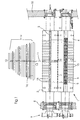
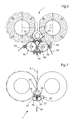
- FIG. 1 the top view of a pair of cutting cylinders is shown Folder and a variety of this cutting cylinder pair of processable web widths out.
- a pair of cutting cylinders comprises a grooving cylinder 2 delimiting a cutting gap 7 and a knife cylinder 4.
- a Nutenbalken 3 inserted, which preferably consists of an elastic material.
- a cutting blade. 5 integrated, which of a leading end of the cutting gap 7 passing Material web individual, flat copies separated.
- the grooved cylinder 2 and the knife cylinder 4 are at their pins in rolling bearings in side walls 8 and 10 of the folder rotatably received.
- On the drive side side wall 8 of the folder is - indicated here by gears - a drive provided, via which the cylinder 2, 3rd of the cutting cylinder pair 1 are set in rotation.
- ring segments 15 are arranged, which in the cutting gap 7 from leading end of the web separated flat copies a wavy Impart stiffening.
- the maximum in the cutting gap 7 as shown in FIG 1 processable material web format is indicated by reference numeral 13; the minimum Material web format is indicated by reference numeral 12.
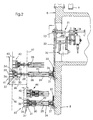
- Figure 2 shows a web width-dependent positionable copy guide on a side wall the folding apparatus, with which side regions to be processed material webs detectable are.
- an actuator flanged On the drive side side wall 8 of a folder is an actuator flanged, which drives a sprocket 23, for example via a bevel gear 21.
- a circulating around the sprocket 23 chain 22 acts as a transmission element and passes the rotational movement of the sprocket 23 to a drive wheel 26 on, which in turn rotatably on a threaded spindle 25 is added.
- the threaded spindle 25 is rotatably embedded on a spindle bearing 27 in a bearing sleeve 24.
- Threaded spindle 25 can be a surrounding actuating cylinder guide 28 in the interior the bearing sleeve 24 on or extend from the interior of the bearing sleeve 24.
- a positioning cylinder 29 preferably as a pneumatic Cylinder is formed.
- a receptacle 30 which the Copy guide takes.
- drives 33 for driven Rotary body 35 designed as rollers, embedded as well as a first carrier 31 and a second carrier 32.
- On each of the carriers 31 and 32 is a driving body of revolution 35, driven by the drive 33 and a driven rotating body 36 in a smaller Diameter added.
- the side regions 46 of a material web 16 engaging band-shaped Transport elements 37 can be provided with a friction-reducing coating be, so that a gentle gripping the side portions 46 of a material web 36th ensured during the action of the band-shaped transport elements 37 is.
- Reference numeral 46 denotes the side edge of a material web 16 which has a minimum Web width - compare reference numeral 12, Figure 1 - has.
- the rotational body 35 and 36 and the so are circulating conveyor belts 37 in an active, i. the side region 46 of the material web 16 capturing position.
- an inactive position 42 i. is at a detection of the side area 46th prevented the web 16 with minimum width 12.
- the Actuating cylinder 29 To bridge the with reference numerals 40 designated travel path from position 41 to position 42 is the Actuating cylinder 29, which in turn is received on the actuating cylinder guide 28.
- the active and the inactive position of the copy guide denotes which these in the processing of a material web 16 with maximum Web width 13 occupies. This is by its side edge 47 in the illustration according to FIG 2 indicated. Even with maximum processable web format is about the actuating cylinder 29, a travel path 40 of the rotary bodies 35 and 36, respectively, on the copy guide in pairs, achievable.
- the feed movement in the area of the web edge 47 takes place analogously to the processing of a material web 16 with a minimum web width 12 via the chain drive 22, 23,26.
- the sprocket 26 drives the enclosed by the bearing sleeve 24 Threaded spindle, on which the actuating cylinder guide 28 arranged movable is and with which the spindle 25 cooperates.
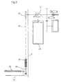
- FIG. 3 shows a first actuator for web-width-dependent Positioning the copy guide closer.
- the schematic reproduction according to Figure 3 is an actuator 20 can be removed, which via a bevel gear on a shaft acts on which a sprocket 23 is formed.
- a drive transmission element 22 chain acting a sprocket 26 is driven, which in turn on the spindle 25 is included, which in turn is enclosed by the bearing sleeve 24 which at the drive side wall 8 of the folder is attached.
- the spindles 25, the of Bearing sleeves 24 are enclosed are also driven directly by drive motors.
- the threaded spindles 25 via gear drives or belt drives or the like into a rotational movement.
- the transmitted to the spindle 25 respectively rotational movement causes the extension and retraction of the actuating cylinder 29 receiving Stellzylinder Assemblyen 28 from the interior or in the interior of the bearing sleeves 24th
- the active Position reproduced - is moved, for example, the rotational body 35, 36th in case of a paper jam to avoid damage in a very short time, within less than a second to go back.
- the first carrier 31 is shown, which with respect to the receptacle 30th is relatively movable.
- an electric motor 33 is accommodated on the receptacle 30, which drives the rotary body 35 with the interposition of a coupling 34. about this on the peripheral surface enclosing transport elements 37, preferably band-shaped Transport belt, the rotating body 36 is moved.
- the rotary bodies 35 and 36 for example, three axially spaced from each other Transport elements 37 added.
- FIG. 4.4 shows the exemplified guide device in an inactive position 44, i. from the web edge 47 of the web 16 returned to maximum web width 13.
- i. inactive position 44 is the position of the actuating cylinder guide 28 with respect to the bearing sleeve 24 and the spindle 25 enclosed by this identical to the positions of these Components as shown in Figure 4.3.
- Only the actuating cylinder 29 has the Recording 30 on the actuating cylinder guide 28 in the direction of the drive side side wall 8 of the folder back, whereby the rotary body 35 and 36 together with the order this circumferential transport elements 37 of the web edge 47 of the web 16 with maximum web width 13 are reset.
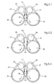
- Figure 5.1 shows the driven rotary body 35, the drive motor 33 is not here is shown.
- the band-shaped transport elements 37 - preferably 3 in number - to.
- the by means of the drive motor 33 in rotation offset rotational elements 35 drive over the circulating transport elements 37 above the latter on the first carrier 31 and second carrier 32 respectively received rotary elements 36 of smaller diameter at.
- the preferably band-shaped configured transport elements 37 run against the Clockwise around and shape the entering in an opening gap 50 between their surfaces flat specimens or the leading end of the web a conveying movement in the direction of copy travel direction, i. in the illustrations according to of Fig. 5.1 to Fig. 5.3 down, on.
- FIG. 6 shows the side view of a cutting cylinder pair the outlet gussets downstream conveyor belts.
- the cutting gap 7 of the cutting cylinder pair according to Figure 6 is an outlet gusset 53rd downstream, in which the leading end of the web 16 enters.
- the leading one End of the material web 16 enters an inlet region 55, which passes through conveyor belts 54 is limited.
- the inventively proposed copy guide 31, 32, 35, 36 supports the trouble-free, i. guided entry of the leading end of the web 16 in the inlet region 55 between the conveyor belts 54, before by a in the cutting gap cross-section a flat copy of the web of material 16 is separated.
- the drive motors are the rotary bodies 35 marked with larger diameter by reference numeral 33.
- transport elements 37 which revolve around the rotary bodies 35 and 36, preferably are driven at machine speed, can be a largely relativ Anthonysbeat Promotion of the leading end 16 of the material web, or after completion of the cross section in the cutting gap 7 of a flat copy 60, achieve.
- FIG. 8 shows an alternative embodiment of another invention Copy guide with conveyor belt driven rotating Transport elements.
- an outlet gusset 53 of a cutting cylinder pair 1 circumferential, preferably band-shaped transport elements 37 assigned.
- these transport elements 37 directly driven by pulleys 56, which also drives the serve at the outlet gusset 53 subsequent conveyor belts 54.
- the pulleys 56 are in the illustration of Figure 8 in an offset arrangement 62 to each other educated.
- the Conveying direction of the circulating, preferably belt-shaped transport elements 37 is identical to the conveying direction of the leading end of the material web 16th or the flat copy 60. With this embodiment of the invention underlying Thought can also be a two-sided enclosure of the preceding End of the web 16 and the surface copy 60 achieve.
- the circulating Transport elements 37 preferably with one of the conveying speed of Material web 16 and the sheet-like copies substantially corresponding speed be driven, cause a relatively speed-free detection of Outer sides of the flat copy 60 and the leading end of the web 16, so that no damage to the separated copies 60 occur.
Landscapes
- Engineering & Computer Science (AREA)
- Mechanical Engineering (AREA)
- Folding Of Thin Sheet-Like Materials, Special Discharging Devices, And Others (AREA)
- Delivering By Means Of Belts And Rollers (AREA)
Description
- Figur 1
- die Draufsicht auf ein Schneidzylinderpaar eines Falzapparates sowie eine Vielzahl von mit diesem verarbeitbarer Bahnbreiten,
- Figur 2
- eine bahnbreitenabhängig an einer Seitenwand des Falzapparates positionierbare Exemplarführung, die Seitenbereiche zu verarbeitender Materialbahnen erfaßt,
- Figur 3
- einen ersten Stellantrieb zur bahnbreitenabhängigen Positionierung der Exemplarführung,
- Figuren 4.1, 4.2
- eine an die Seitenkante einer minimal verarbeitbaren Bahnbreite angestellte Exemplarführung in aktiver und inaktiver Position,
- Figuren 4.3, 4.4
- eine an die Seitenkante eines maximal verarbeitbaren Bahnformates angestellte Exemplarführung sowohl in aktiver wie auch in inaktiver Position,
- Figur 5.1 bis 5.3
- verschiedene Öffnungsspaltgeometrien zwischen den die Exemplare ergreifenden umlaufenden Transportelementen,
- Figur 6
- die Seitenansicht eines Schneidzylinderpaares mit dessen Auslaufzwickel nachgeordneten Transportbändern,
- Figur 7
- die im Auslaufzwickel des Schneidzylinderpaares positionierte Exemplarführung in Seitenansicht mit angetriebenen, umlaufenden Transportelementen und
- Figur 8
- eine Ausführungsvariante einer erfindungsgemäßen Exemplarführung mit über Transportbänder direkt angetriebenen, umlaufenden Transportelementen.
- 1
- Schneidzylinderpaar
- 2
- Nutenzylinder
- 3
- Nutenbalken
- 4
- Messerzylinder
- 5
- Schneidmesser
- 6
- Messerlagerung
- 7
- Schneidspalt
- 8
- Seitenwand Antriebsseite
- 9
- Antrieb
- 10
- Seitenwand Bedienseite
- 11
- Maschinenmitte
- 12
- minimale Bahnbreite
- 13
- maximale Bahnbreite
- 14
- weitere Bahnbreiten
- 15
- Ringsegmente
- 16
- Materialbahn
- 20
- Stellantrieb
- 21
- Kegelradgetriebe
- 22
- Übertragungselement
- 23
- Rad
- 24
- Lagerhülse
- 25
- Spindel
- 26
- Antriebsrad
- 27
- Spindellager
- 28
- Stellzylinderführung
- 29
- Stellzylinder
- 30
- Aufnahme
- 31
- erster Träger
- 32
- zweiter Träger
- 33
- Antriebsmotor
- 34
- Kupplung
- 35
- treibende Rollen
- 36
- angetriebene Rollen
- 37
- Transportelemente
- 40
- Verfahrweg
- 41
- aktive Position minimale Bahnbreite
- 42
- inaktive Position minimale Bahnbreite
- 43
- aktive Position maximale Bahnbreite
- 44
- inaktive Position maximale Bahnbreite
- 45
- Verfahrweg Aufnahme 30
- 46
- Bahnkante minimale Bahnbreite
- 47
- Bahnkante maximale Bahnbreite
- 50
- Öffnungsspalt
- 51
- oberer Abstand
- 52
- unterer Abstand
- 53
- Auslaufzwickel
- 54
- Transportbänder
- 55
- Einlaufbereich
- 56
- Umlenkrollen
- 60
- Exemplar
- 61
- Umlaufrollen
- 62
- versetzte Anordnung
- 63
- Erfassungsbereich
Claims (16)
- Vorrichtung zum Führen von flächigen Exemplaren (60), die von einer Materialbahn (16) in einem Schneidspalt (7) eines Schneidzylinderpaares (1) abgetrennt werden, mit einer im Auslaufzwickel (53) des Schneidzylinderpaares (1) angeordneten Exemplarführung (31, 32, 35, 36), welche die vorlaufenden Enden der flächigen Exemplare (60) zur Führung derselben erfasst, dadurch gekennzeichnet, dass die Exemplarführung (31, 32, 35, 36) umlaufende Transportelemente (37) umfasst, die über Stellantriebe (20, 22, 26, 29) zur Anpassung an unterschiedliche Positionen und Breiten (12, 13, 14) von Materialbahnen (16) in lateraler Richtung verfahrbar sind.
- Vorrichtung gemäß Anspruch 1, dadurch gekennzeichnet, daß jeweils eine Exemplarführung (31, 32, 35, 36) den Seitenbereichen (46, 47) der Materialbahn (16) zugeordnet ist.
- Vorrichtung gemäß Anspruch 2, dadurch gekennzeichnet, daß die beidseits der zu verarbeitenden Materialbahn (16) angeordneten Exemplarführungen (31, 32, 35, 36) symmetrisch in bezug auf die Maschinenmitte (11) verfahrbar sind
- Vorrichtung gemäß Anspruch 2, dadurch gekennzeichnet, daß die beidseits der zu verarbeitenden Materialbahn (16) angeordneten Exemplarführungen (31, 32, 35, 36) unabhängig voneinander in bezug auf die Maschinenmitte (11) verfahrbar sind.
- Vorrichtung gemäß Anspruch 1, dadurch gekennzeichnet, daß jeder Exemplarführung (31, 32, 35, 36) ein erster Stellantrieb (20, 22, 26) zugeordnet ist, welcher diese innerhalb eines Verfahrweges (45) im Bereich der Seitenkanten (46, 47) der Materialbahn (16) entsprechend der Breite (12, 13, 14) positioniert.
- Vorrichtung gemäß Anspruch 1, dadurch gekennzeichnet, daß jede Exemplarführung (31, 32, 35, 36) paarweise angetriebene Rotationskörper (36) sowie treibende Rotationskörper (35) enthält, um welche die Transportelemente (37) umlaufen.
- Vorrichtung gemäß Anspruch 6, dadurch gekennzeichnet, daß die treibenden Rotationskörper (35) mittels in die Exemplarführungen (31, 32, 35, 36) integrierte Antriebe (33) angetrieben sind.
- Vorrichtung gemäß Anspruch 6 oder 7, dadurch gekennzeichnet, daß jede Exemplarführung (31, 32, 35, 36) einen Stellzylinder (29) umfaßt, mit welchem eine die Rotationskörper (35, 36) umfassende Aufnahme (30) in eine die Materialbahn (16) erfassende Position (41, 43) sowie in eine die Materialbahn (16) nicht erfassende Position (42, 44) verfahrbar ist.
- Vorrichtung nach einem der Ansprüche 6 bis 8, dadurch gekennzeichnet, daß zwischen den Paaren von Rotationskörpern (35, 36) ein in seiner Öffnungsweite (51) variabler Spalt (50) ausgebildet ist.
- Vorrichtung gemäß Anspruch 9, dadurch gekennzeichnet, daß der Spalt (50) durch die angetriebenen Transportelemente (37) begrenzt ist.
- Vorrichtung gemäß Anspruch 9 oder 10, dadurch gekennzeichnet, daß die angetriebenen Rotationskörper (36) bezogen auf die diese jeweils antreibenden Rotationskörper (36) in verschwenkbaren Trägern (31, 32) aufgenommen sind.
- Vorrichtung gemäß Anspruch 11, dadurch gekennzeichnet, daß die verschwenkbaren Träger (31, 32) zur Variation der Öffnungsweite (51) des Spaltes (50) in bezug auf die treibenden Rotationskörper (35) verschwenkbar sind.
- Vorrichtung nach einem der vorhergehenden Ansprüche, dadurch gekennzeichnet, daß die Transportelemente (37) als voneinander in axiale Richtung beabstandete Transportbänder ausgeführt sind.
- Vorrichtung nach einem der vorhergehenden Ansprüche, dadurch gekennzeichnet, daß die Transportelemente (37) die den Schneidspalt 7 verlassende Materialbahn (16) beidseits relativgeschwindigkeitsfrei entlang eines Erfassungsbereiches (63) führen.
- Vorrichtung nach einem der vorhergehenden Ansprüche, dadurch gekennzeichnet, dass die angetriebenen Transportelemente sowohl auf einander gegenüberliegenden Seiten der Materialbahn (16) als auch beiderseits der Materialbahn (16) angeordnet sind.
- Falzapparat mit einer Vorrichtung zum Führen einer Materialbahn (16) gemäß einem oder mehreren der vorhergehenden Ansprüche.
Applications Claiming Priority (2)
| Application Number | Priority Date | Filing Date | Title |
|---|---|---|---|
| DE10107368A DE10107368A1 (de) | 2001-02-16 | 2001-02-16 | Vorrichtung zum Führen flächiger Exemplare in Falzapparaten |
| DE10107368 | 2001-02-16 |
Publications (3)
| Publication Number | Publication Date |
|---|---|
| EP1232983A2 EP1232983A2 (de) | 2002-08-21 |
| EP1232983A3 EP1232983A3 (de) | 2004-01-07 |
| EP1232983B1 true EP1232983B1 (de) | 2005-03-23 |
Family
ID=7674331
Family Applications (1)
| Application Number | Title | Priority Date | Filing Date |
|---|---|---|---|
| EP02001148A Expired - Lifetime EP1232983B1 (de) | 2001-02-16 | 2002-01-25 | Vorrichtung zum Führen flächiger Exemplare in Falzapparaten |
Country Status (4)
| Country | Link |
|---|---|
| US (1) | US6752078B2 (de) |
| EP (1) | EP1232983B1 (de) |
| JP (1) | JP2002255391A (de) |
| DE (2) | DE10107368A1 (de) |
Families Citing this family (2)
| Publication number | Priority date | Publication date | Assignee | Title |
|---|---|---|---|---|
| DE10160754C2 (de) * | 2001-11-14 | 2003-10-09 | Koenig & Bauer Ag | Fördereinheit zum Fördern flacher Gegenstände |
| DE202008016465U1 (de) * | 2008-12-15 | 2010-02-11 | Manroland Ag | Bandleitungsvorrichtung eines Falzapparats |
Family Cites Families (25)
| Publication number | Priority date | Publication date | Assignee | Title |
|---|---|---|---|---|
| DE1248066B (de) | 1965-02-08 | 1967-08-24 | Planeta Veb Druckmasch Werke | Einrichtung an Mehrfarben-Rotationsdruck-maschinen zum passgerechten Verbinden von Druckwerken |
| US3518940A (en) * | 1967-06-30 | 1970-07-07 | Cameron Machine Co | Endless belt printing machine |
| FR2097292A5 (de) | 1970-07-01 | 1972-03-03 | Guinard Pompes | |
| US4069959A (en) * | 1976-10-27 | 1978-01-24 | Butler Automatic, Inc. | Web guide apparatus |
| US4204619A (en) * | 1978-05-04 | 1980-05-27 | Damour Lawrence R | Pivoted web guide for travelling strip |
| DE3139117C1 (de) * | 1981-10-01 | 1983-04-21 | M.A.N.- Roland Druckmaschinen AG, 6050 Offenbach | Variabler Falzapparat mit einem Schneidzylinderpaarund einem unterhalb diesem angeordneten Abreisswalzenpaar |
| US4477006A (en) * | 1983-03-03 | 1984-10-16 | Robert L. Fife | Offset pivot guiding assembly |
| DE3525040C2 (de) * | 1985-07-13 | 1994-05-11 | Bell & Howell Co | Einrichtung zur Umlenkung der Förderrichtung von Papierblättern |
| DE3917845A1 (de) * | 1989-06-01 | 1990-12-06 | Roland Man Druckmasch | Schneidvorrichtung fuer ein falzwerk einer druckmaschine |
| DE4128864C2 (de) | 1991-08-30 | 1994-10-13 | Roland Man Druckmasch | Auflagerverbindung für verschraubte Gestellwände |
| DE4323524C2 (de) | 1993-07-14 | 1996-03-14 | Kostal Leopold Gmbh & Co Kg | Dichtungsanordnung |
| US5558263A (en) * | 1994-07-26 | 1996-09-24 | Eastman Kodak Company | Apparatus and method for non-contact active tensioning and steering of moving webs |
| DE4442279C2 (de) | 1994-11-28 | 1999-09-09 | Heidelberger Druckmasch Ag | Druckwerksschaltung |
| FR2731383B1 (fr) | 1995-03-07 | 1997-05-30 | Heidelberg Harris Sa | Dispositif de transport d'exemplaires |
| FR2751630B1 (fr) * | 1996-07-23 | 1998-10-23 | Heidelberg Harris Sa | Dispositif de guidage de cahiers a la sortie d'un groupe de deux cylindres coupeurs d'une plieuse |
| DE19749593A1 (de) * | 1997-11-10 | 1999-05-20 | Moelnlycke Ab | Vorrichtung zum Transportieren kontinuierlicher längserstreckter Materialbahnen |
| FR2771958B1 (fr) * | 1997-12-08 | 2000-02-25 | Heidelberger Druckmasch Ag | Dispositif de coupe transversale de bandes de matiere et plieuse avec ou sans pointure comportant un tel dispositif de coupe |
| DE19804735B4 (de) * | 1998-02-06 | 2006-06-29 | Windmöller & Hölscher Kg | Verfahren und Vorrichtung zum Ausrichten zweier zu einer mehrlagigen Bahn zusammengeführter Bahnen |
| US6195112B1 (en) * | 1998-07-16 | 2001-02-27 | Eastman Kodak Company | Steering apparatus for re-inkable belt |
| US6164201A (en) * | 1998-09-11 | 2000-12-26 | Heidelberger Druckmachinen Ag | Method and apparatus for web steering |
| US6604444B1 (en) * | 1998-10-29 | 2003-08-12 | Heidelberger Druckmaschinen Ag | Low maintenance cutting rubber |
| DE19959152A1 (de) * | 1999-12-08 | 2001-06-13 | Heidelberger Druckmasch Ag | Einrichtung zur Führung von Materialbahnen in Rotationsdruckmaschinen |
| DE10000507B4 (de) | 2000-01-08 | 2006-03-16 | Koenig & Bauer Ag | Verfahren und Vorrichtung zum Aus- und Einbau von rotationssymmetrischen Teilen |
| DE20005844U1 (de) | 2000-03-29 | 2000-07-27 | Räder, Gerhard, 90765 Fürth | Staubdichte Abdeckung für Transportkästen |
| US6295925B1 (en) * | 2000-05-22 | 2001-10-02 | Sarni/Bria Flexographic Llc | Web tension control system and method for flexographic tag and label presses |
-
2001
- 2001-02-16 DE DE10107368A patent/DE10107368A1/de not_active Withdrawn
-
2002
- 2002-01-25 DE DE50202517T patent/DE50202517D1/de not_active Expired - Fee Related
- 2002-01-25 EP EP02001148A patent/EP1232983B1/de not_active Expired - Lifetime
- 2002-02-14 JP JP2002037025A patent/JP2002255391A/ja active Pending
- 2002-02-19 US US10/078,116 patent/US6752078B2/en not_active Expired - Fee Related
Also Published As
| Publication number | Publication date |
|---|---|
| US20020112625A1 (en) | 2002-08-22 |
| EP1232983A3 (de) | 2004-01-07 |
| EP1232983A2 (de) | 2002-08-21 |
| US6752078B2 (en) | 2004-06-22 |
| JP2002255391A (ja) | 2002-09-11 |
| DE10107368A1 (de) | 2002-08-29 |
| DE50202517D1 (de) | 2005-04-28 |
Similar Documents
| Publication | Publication Date | Title |
|---|---|---|
| DE2426217B2 (de) | Vorrichtung zum Transport von einen Querschneider verlassenden einzelnen Bogen | |
| EP1043257A2 (de) | Vorrichtung zum Umlenken eines Stroms flacher Produkte in verschiedene Richtungen | |
| EP1274547B1 (de) | Vorrichtung zum querschneiden von mindestens einer bahn in einem falzapparat | |
| EP1486443B1 (de) | Vorrichtung zum Ausschleusen von Signaturen oder eines Anfanges einer Bahn oder eines Bahnstranges aus einem Falzapparat | |
| EP0576810B1 (de) | Einrichtung zur Unterstützung des kontrollierten Exemplartransportes im Falzapparat von Rotationsdruckmaschinen | |
| DE10020316A1 (de) | Zylinderanordnung für einen Falzapparat einer Rotationsdruckmaschine | |
| EP1232983B1 (de) | Vorrichtung zum Führen flächiger Exemplare in Falzapparaten | |
| EP1097892B1 (de) | Vorrichtung und Verfahren zum Schneiden und Umlenken von Signaturen | |
| DE19932070A1 (de) | Exemplarführungseinrichtung mit variabler Geometrie | |
| EP1112952B1 (de) | Vorrichtung zum fortlaufenden Falzen von flachem Material | |
| EP1108672B1 (de) | Verfahren und Vorrichtung zum linearen Falzen | |
| EP1110894B1 (de) | Verfahren und Vorrichtung zum Falzen von Materialbogen | |
| EP1184314A2 (de) | Vorrichtung zum Führen von Signaturen, insbesondere im Bereich eines Auslauf-Zwickels einer Schneidzylinderanordnung in einem Falzapparat einer Rotationsdruckmaschine | |
| DE102005008000B4 (de) | Vorrichtung zum Fördern von Produkten | |
| DE10235897A1 (de) | Bedruckstoff verarbeitende Maschine mit einer Transportbandeinrichtung | |
| DE4217814C2 (de) | Einrichtung zur Unterstützung des kontrollierten Exemplartransportes im Falzapparat von Rotationsdruckmaschinen | |
| EP1522515B1 (de) | Längsfalzvorrichtung | |
| DE19754151A9 (de) | Einrichtung zur Verbesserung der Falzgenauigkeit im Falzapparat | |
| DE19754151A1 (de) | Einrichtung zur Verbesserung der Falzgenauigkeit im Falzapparat | |
| EP1201591A1 (de) | Exemplarführung für flächige Exemplare in Falzapparaten | |
| EP0716038A2 (de) | Falzapparat mit einer Produkthalteeinrichtung | |
| DE10018775A1 (de) | Verfahren und Vorrichtung zum Transportieren einer Bahn oder von Signaturen in einem Falzapparat | |
| DE20022734U1 (de) | Vorrichtung zum Transportieren von Signaturen in einem Falzapparat | |
| DE29718924U1 (de) | Schrank | |
| DE102005034565A1 (de) | Falzapparat und ein Doppel-Falzapparat |
Legal Events
| Date | Code | Title | Description |
|---|---|---|---|
| PUAI | Public reference made under article 153(3) epc to a published international application that has entered the european phase |
Free format text: ORIGINAL CODE: 0009012 |
|
| AK | Designated contracting states |
Kind code of ref document: A2 Designated state(s): AT BE CH CY DE DK ES FI FR GB GR IE IT LI LU MC NL PT SE TR |
|
| AX | Request for extension of the european patent |
Free format text: AL;LT;LV;MK;RO;SI |
|
| RIN1 | Information on inventor provided before grant (corrected) |
Inventor name: PHILIPPE, ROBERT Inventor name: BLANCHARD, ALAIN Inventor name: CHAGNON, FRANCK |
|
| PUAL | Search report despatched |
Free format text: ORIGINAL CODE: 0009013 |
|
| AK | Designated contracting states |
Kind code of ref document: A3 Designated state(s): AT BE CH CY DE DK ES FI FR GB GR IE IT LI LU MC NL PT SE TR |
|
| AX | Request for extension of the european patent |
Extension state: AL LT LV MK RO SI |
|
| 17P | Request for examination filed |
Effective date: 20031217 |
|
| GRAP | Despatch of communication of intention to grant a patent |
Free format text: ORIGINAL CODE: EPIDOSNIGR1 |
|
| AKX | Designation fees paid |
Designated state(s): DE FR GB IT |
|
| RAP1 | Party data changed (applicant data changed or rights of an application transferred) |
Owner name: HEIDELBERG WEB SYSTEMS, S.A. |
|
| GRAS | Grant fee paid |
Free format text: ORIGINAL CODE: EPIDOSNIGR3 |
|
| RAP1 | Party data changed (applicant data changed or rights of an application transferred) |
Owner name: GOSS INTERNATIONAL MONTATAIRE S.A. |
|
| GRAA | (expected) grant |
Free format text: ORIGINAL CODE: 0009210 |
|
| AK | Designated contracting states |
Kind code of ref document: B1 Designated state(s): DE FR GB IT |
|
| PG25 | Lapsed in a contracting state [announced via postgrant information from national office to epo] |
Ref country code: IT Free format text: LAPSE BECAUSE OF FAILURE TO SUBMIT A TRANSLATION OF THE DESCRIPTION OR TO PAY THE FEE WITHIN THE PRESCRIBED TIME-LIMIT;WARNING: LAPSES OF ITALIAN PATENTS WITH EFFECTIVE DATE BEFORE 2007 MAY HAVE OCCURRED AT ANY TIME BEFORE 2007. THE CORRECT EFFECTIVE DATE MAY BE DIFFERENT FROM THE ONE RECORDED. Effective date: 20050323 |
|
| REG | Reference to a national code |
Ref country code: GB Ref legal event code: FG4D Free format text: NOT ENGLISH |
|
| REG | Reference to a national code |
Ref country code: IE Ref legal event code: FG4D Free format text: GERMAN |
|
| REF | Corresponds to: |
Ref document number: 50202517 Country of ref document: DE Date of ref document: 20050428 Kind code of ref document: P |
|
| GBT | Gb: translation of ep patent filed (gb section 77(6)(a)/1977) |
Effective date: 20050718 |
|
| PLBE | No opposition filed within time limit |
Free format text: ORIGINAL CODE: 0009261 |
|
| STAA | Information on the status of an ep patent application or granted ep patent |
Free format text: STATUS: NO OPPOSITION FILED WITHIN TIME LIMIT |
|
| 26N | No opposition filed |
Effective date: 20051227 |
|
| ET | Fr: translation filed | ||
| PGFP | Annual fee paid to national office [announced via postgrant information from national office to epo] |
Ref country code: GB Payment date: 20070125 Year of fee payment: 6 |
|
| PGFP | Annual fee paid to national office [announced via postgrant information from national office to epo] |
Ref country code: DE Payment date: 20070228 Year of fee payment: 6 |
|
| PGFP | Annual fee paid to national office [announced via postgrant information from national office to epo] |
Ref country code: FR Payment date: 20070117 Year of fee payment: 6 |
|
| GBPC | Gb: european patent ceased through non-payment of renewal fee |
Effective date: 20080125 |
|
| PG25 | Lapsed in a contracting state [announced via postgrant information from national office to epo] |
Ref country code: DE Free format text: LAPSE BECAUSE OF NON-PAYMENT OF DUE FEES Effective date: 20080801 |
|
| REG | Reference to a national code |
Ref country code: FR Ref legal event code: ST Effective date: 20081029 |
|
| PG25 | Lapsed in a contracting state [announced via postgrant information from national office to epo] |
Ref country code: GB Free format text: LAPSE BECAUSE OF NON-PAYMENT OF DUE FEES Effective date: 20080125 |
|
| PG25 | Lapsed in a contracting state [announced via postgrant information from national office to epo] |
Ref country code: FR Free format text: LAPSE BECAUSE OF NON-PAYMENT OF DUE FEES Effective date: 20080131 |