EP1224037B1 - Procede et dispositif permettant de diriger le son - Google Patents
Procede et dispositif permettant de diriger le son Download PDFInfo
- Publication number
- EP1224037B1 EP1224037B1 EP00964444A EP00964444A EP1224037B1 EP 1224037 B1 EP1224037 B1 EP 1224037B1 EP 00964444 A EP00964444 A EP 00964444A EP 00964444 A EP00964444 A EP 00964444A EP 1224037 B1 EP1224037 B1 EP 1224037B1
- Authority
- EP
- European Patent Office
- Prior art keywords
- output
- signal
- array
- input signal
- transducers
- Prior art date
- Legal status (The legal status is an assumption and is not a legal conclusion. Google has not performed a legal analysis and makes no representation as to the accuracy of the status listed.)
- Expired - Lifetime
Links
Images


Classifications
-
- H—ELECTRICITY
- H04—ELECTRIC COMMUNICATION TECHNIQUE
- H04R—LOUDSPEAKERS, MICROPHONES, GRAMOPHONE PICK-UPS OR LIKE ACOUSTIC ELECTROMECHANICAL TRANSDUCERS; DEAF-AID SETS; PUBLIC ADDRESS SYSTEMS
- H04R1/00—Details of transducers, loudspeakers or microphones
- H04R1/20—Arrangements for obtaining desired frequency or directional characteristics
- H04R1/32—Arrangements for obtaining desired frequency or directional characteristics for obtaining desired directional characteristic only
-
- H—ELECTRICITY
- H04—ELECTRIC COMMUNICATION TECHNIQUE
- H04S—STEREOPHONIC SYSTEMS
- H04S5/00—Pseudo-stereo systems, e.g. in which additional channel signals are derived from monophonic signals by means of phase shifting, time delay or reverberation
- H04S5/02—Pseudo-stereo systems, e.g. in which additional channel signals are derived from monophonic signals by means of phase shifting, time delay or reverberation of the pseudo four-channel type, e.g. in which rear channel signals are derived from two-channel stereo signals
-
- F—MECHANICAL ENGINEERING; LIGHTING; HEATING; WEAPONS; BLASTING
- F41—WEAPONS
- F41H—ARMOUR; ARMOURED TURRETS; ARMOURED OR ARMED VEHICLES; MEANS OF ATTACK OR DEFENCE, e.g. CAMOUFLAGE, IN GENERAL
- F41H13/00—Means of attack or defence not otherwise provided for
- F41H13/0043—Directed energy weapons, i.e. devices that direct a beam of high energy content toward a target for incapacitating or destroying the target
- F41H13/0081—Directed energy weapons, i.e. devices that direct a beam of high energy content toward a target for incapacitating or destroying the target the high-energy beam being acoustic, e.g. sonic, infrasonic or ultrasonic
-
- G—PHYSICS
- G10—MUSICAL INSTRUMENTS; ACOUSTICS
- G10K—SOUND-PRODUCING DEVICES; METHODS OR DEVICES FOR PROTECTING AGAINST, OR FOR DAMPING, NOISE OR OTHER ACOUSTIC WAVES IN GENERAL; ACOUSTICS NOT OTHERWISE PROVIDED FOR
- G10K15/00—Acoustics not otherwise provided for
- G10K15/04—Sound-producing devices
-
- H—ELECTRICITY
- H04—ELECTRIC COMMUNICATION TECHNIQUE
- H04R—LOUDSPEAKERS, MICROPHONES, GRAMOPHONE PICK-UPS OR LIKE ACOUSTIC ELECTROMECHANICAL TRANSDUCERS; DEAF-AID SETS; PUBLIC ADDRESS SYSTEMS
- H04R3/00—Circuits for transducers, loudspeakers or microphones
- H04R3/005—Circuits for transducers, loudspeakers or microphones for combining the signals of two or more microphones
-
- H—ELECTRICITY
- H04—ELECTRIC COMMUNICATION TECHNIQUE
- H04R—LOUDSPEAKERS, MICROPHONES, GRAMOPHONE PICK-UPS OR LIKE ACOUSTIC ELECTROMECHANICAL TRANSDUCERS; DEAF-AID SETS; PUBLIC ADDRESS SYSTEMS
- H04R3/00—Circuits for transducers, loudspeakers or microphones
- H04R3/12—Circuits for transducers, loudspeakers or microphones for distributing signals to two or more loudspeakers
-
- H—ELECTRICITY
- H04—ELECTRIC COMMUNICATION TECHNIQUE
- H04R—LOUDSPEAKERS, MICROPHONES, GRAMOPHONE PICK-UPS OR LIKE ACOUSTIC ELECTROMECHANICAL TRANSDUCERS; DEAF-AID SETS; PUBLIC ADDRESS SYSTEMS
- H04R2203/00—Details of circuits for transducers, loudspeakers or microphones covered by H04R3/00 but not provided for in any of its subgroups
- H04R2203/12—Beamforming aspects for stereophonic sound reproduction with loudspeaker arrays
Definitions
- This invention relates to steerable acoustic antennae, and concerns in particular digital electronically-steerable acoustic antennae.
- Phased array antennae are well known in the art in both the electromagnetic and the ultrasonic acoustic fields. They are less well known, but exist in simple forms, in the sonic (audible) acoustic area. These latter are relatively crude, and the invention seeks to provide improvements related to a superior audio acoustic array capable of being steered so as to direct its output more or less at will.
- WO 96/31086 describes a system which uses a unary coded signal to drive a an array of output transducers. Each transducer is capable of creating a sound pressure pulse and is not able to reproduce the whole of the signal to be output.
- the present invention addresses the problem that traditional stereo or surround sound devices have many wires and loudspeaker units with correspondingly set-up times. This aspect therefore relates to the creation of a true stereo or surround-sound field without the wiring and separated loudspeakers traditionally associated with stereo and surround-sound systems.
- the invention provides a method of causing plural input signals representing respective channels to appear to emanate from respective different positions in space, said method comprising:
- an apparatus for causing plural input signals representing respective channels to appear to emanate from respective different positions in space comprising:
- the invention is applicable to a preferably fully digital steerable acoustic phased array antenna (a Digital Phased-Array Antennae, or DPAA) system comprising a plurality of spatially-distributed sonic electroacoustic transducers (SETs) arranged in a two-dimensional array and each connected to the same digital signal input via an input signal Distributor which modifies the input signal prior to feeding it to each SET in order to achieve the desired directional effect.
- a Digital Phased-Array Antennae or DPAA
- SETs spatially-distributed sonic electroacoustic transducers
- the SETs are preferably arranged in a plane or curved surface (a Surface), rather than randomly in space. They may also, however, be in the form of a 2-dimensional stack of two or more adjacent sub-arrays - two or more closely-spaced parallel plane or curved surfaces located one behind the next.
- the SETs making up the array are preferably closely spaced, and ideally completely fill the overall antenna aperture. This is impractical with real circular-section SETs but may be achieved with triangular, square or hexagonal section SETs, or in general with any section which tiles the plane. Where the SET sections do not tile the plane, a close approximation to a filled aperture may be achieved by making the array in the form of a stack or arrays - ie, three-dimensional - where at least one additional Surface of SETs is mounted behind at least one other such Surface, and the SETs in the or each rearward array radiate between the gaps in the frontward array(s).
- the SETs are preferably similar, and ideally they are identical. They are, of course, sonic - that is, audio - devices, and most preferably they are able uniformly to cover the entire audio band from perhaps as low as (or lower than) 20Hz, to as much as 20KHz or more (the Audio Band). Alternatively, there can be used SETs of different sonic capabilities but together covering the entire range desired. Thus, multiple different SETs may be physically grouped together to form a composite SET (CSET) wherein the groups of different SETs together can cover the Audio Band even though the individual SETs cannot. As a further variant, SETs each capable of only partial Audio Band coverage can be not grouped but instead scattered throughout the array with enough variation amongst the SETs that the array as a whole has complete or more nearly complete coverage of the Audio Band.
- CSET composite SET
- CSET contains several (typically two) identical transducers, each driven by the same signal. This reduces the complexity of the required signal processing and drive electronics while retaining many of the advantages of a large DPAA.
- position of a CSET is referred to hereinafter, it is to be understood that this position is the centroid of the CSET as a whole, i.e. the centre of gravity of all of the individual SETs making up the CSET.
- the spacing of the SETs or CSET that is, the general layout and structure of the array and the way the individual transducers are disposed therein - is preferably regular, and their distribution about the Surface is desirably symmetrical.
- the SETs are most preferably spaced in a triangular, square or hexagonal lattice.
- the type and orientation of the lattice can be chosen to control the spacing and direction of side-lobes.
- each SET preferably has an omnidirectional input/output characteristic in at least a hemisphere at all sound wavelengths which it is capable of effectively radiating (or receiving).
- Each output SET may take any convenient or desired form of sound radiating device (for example, a conventional loudspeaker), and though they are all preferably the same they could be different.
- the loudspeakers may be of the type known as pistonic acoustic radiators (wherein the transducer diaphragm is moved by a piston) and in such a case the maximum radial extent of the piston-radiators (eg, the effective piston diameter for circular SETs) of the individual SETs is preferably as small as possible, and ideally is as small as or smaller than the acoustic wavelength of the highest frequency in the Audio Band (eg in air, 20KHz sound waves have a wavelength of approximately 17mm, so for circular pistonic transducers, a maximum diameter of about 17mm is preferable).
- the overall dimensions of the or each array of SETs in the plane of the array are very preferably chosen to be as great as or greater than the acoustic wavelength in air of the lowest frequency at which it is intended to significantly affect the polar radiation pattern of the array.
- the invention is applicable to fully digital steerable sonic/ audible acoustic phased array antenna system, and while the actual transducers can be driven by an analogue signal most preferably they are driven by a digital power amplifier.
- a typical such digital power amplifier incorporates: a PCM signal input; a clock input (or a means of deriving a clock from the input PCM signal); an output clock, which is either internally generated, or derived from the input clock or from an additional output clock input; and an optional output level input, which may be either a digital (PCM) signal or an analogue signal (in the latter case, this analogue signal may also provide the power for the amplifier output).
- a characteristic of a digital power amplifier is that, before any optional analogue output filtering, its output is discrete valued and stepwise continuous, and can only change level at intervals which match the output clock period.
- the discrete output values are controlled by the optional output level input, where provided.
- the output signal's average value over any integer multiple of the input sample period is representative of the input signal.
- the output signal's average value tends towards the input signal's average value over periods greater than the input sample period.
- Preferred forms of digital power amplifier include bipolar pulse width modulators, and one-bit binary modulators.
- DAC digital-to-analogue converter
- linear power amplifier for each transducer drive channel
- the DPAA has one or more digital input terminals (Inputs). When more than one input terminal is present, it is necessary to provide means for routing each input signal to the individual SETs.
- each of the inputs may be connected to each of the SETs via one or more input signal Distributors.
- an input signal is fed to a single Distributor, and that single Distributor has a separate output to each of the SETs (and the signal it outputs is suitably modified, as discussed hereinafter, to achieve the end desired).
- a plurality of Distributors each feeding all the SETs - the outputs from each Distributor to any one SET have to be combined, and conveniently this is done by an adder circuit prior to any further modification the resultant feed may undergo.
- the Input terminals preferably receive one or more digital signals representative of the sound or sounds to be handled by the DPAA (Input Signals).
- the original electrical signal defining the sound to be radiated may be in an analogue form, and therefore the system of the invention may include one or more analogue-to-digital converters (ADCs) connected each between an auxiliary analogue input terminal (Analogue Input) and one of the Inputs, thus allowing the conversion of these external analogue electrical signals to internal digital electrical signals, each with a specific (and appropriate) sample rate Fs i .
- the signals handled are time-sampled quantized digital signals representative of the sound waveform or waveforms to be reproduced by the DPAA.
- a digital sample-rate-converter is required to be provided between an Input and the remaining internal electronic processing system of the DPAA if the signal presented at that input is not synchronised with the other components of and input signals to, the DPAA.
- the output of each DSRC is clocked in-phase with and at the same rate as all the other DSRCs, so that disparate external signals from the Inputs with different clock rates and/or phases can be brought together within the DPAA, synchronised, and combined meaningfully into one or more composite internal data channels.
- the DSRC may be omitted on one "master"channel if that input signal's clock is then used as the master clock for all the other DSRC outputs. Where several external input signals already share a common external or internal data timing clock then there may effectively be several such "master" channels.
- No DSRC is required on any analogue input channel as its analogue to digital conversion process may be controlled by the internal master clock for direct synchronisation.
- the DPAA of the invention incorporates a Distributor which modifies the input signal prior to feeding it to each SET in order to achieve the desired directional effect.
- a Distributor is a digital device, or piece of software, with one input and multiple outputs.
- One of the DPAA's Input Signals is fed into its input. It preferably has one output for each SET; alternatively, one output can be shared amongst a number of the SETs or the elements of a CSET.
- the Distributor sends generally differently modified versions of the input signal to each of its outputs.
- the modifications can be either fixed, or adjustable using a control system.
- the modifications carried out by the distributor can comprise applying a signal delay, applying amplitude control and/or adjustably digitally filtering.
- SDM signal delay means
- ACM amplitude control means
- ADFs adjustable digital filters
- the ADFs can be arranged to apply delays to the signal by appropriate choice of filter coefficients. Further, this delay can be made frequency dependent such that different frequencies of the input signal are delayed by different amounts and the filter can produce the effect of the sum of any number of such delayed versions of the signal.
- the terms "delaying” or “delayed” used herein should be construed as incorporating the type of delays applied by ADFs as well as SDMs.
- the delays can be of any useful duration including zero, but in general, at least one replicated input signal is delayed by a non-zero value.
- the signal delay means are variable digital signal time-delay elements.
- SDM signal delay means
- the DPAA will operate over a broad frequency band (eg the Audio Band).
- the amplitude control means is conveniently implemented as digital amplitude control means for the purposes of gross beam shape modification. It may comprise an amplifier or alternator so as to increase or decrease the magnitude of an output signal. Like the SDM, there is preferably an adjustable ACM for each Input/SET combination.
- the amplitude control means is preferably arranged to apply differing amplitude control to each signal output from the Distributor so as to counteract for the fact that the DPAA is of finite size. This is conveniently achieved by normalising the magnitude of each output signal in accordance with a predefined curve such as a Gaussian curve or a raised cosine curve.
- a predefined curve such as a Gaussian curve or a raised cosine curve.
- ADF digital filters
- group delay and magnitude response vary in a specified way as a function of frequency (rather than just a simple time delay or level change)
- simple delay elements may be used in implementing these filters to reduce the necessary computation.
- This approach allows control of the DPAA radiation pattern as a function of frequency which allows control of the radiation pattern of the DPAA to be adjusted separately in different frequency bands (which is useful because the size in wavelengths of the DPAA radiating area, and thus its directionality, is otherwise a strong function of frequency).
- the SDM delays, ACM gains and ADF coefficients can be fixed, varied in response to User input, or under automatic control. Preferably, any changes required while a channel is in use are made in many small increments so that no discontinuity is heard. These increments can be chosen to define predetermined "roll-off” and "attack” rates which describe how quickly the parameters are able to change.
- this combination of digital signals is conveniently done by digital algebraic addition of the I separate delayed signals - ie the signal to each SET is a linear combination of separately modified signals from each of the I Inputs. It is because of this requirement to perform digital addition of signals originating from more than one Input that the DSRCs (see above) are desirable, to synchronize these external signals, as it is generally not meaningful to perform digital addition on two or more digital signals with different clock rates and/or phases.
- the input digital signals are preferably passed through an oversampling-noise-shaping-quantizer (ONSQ) which reduces their bit-width and increases their sample-rate whilst keeping their signal to noise ratio (SNR) in the acoustic band largely unchanged.
- ONSQ oversampling-noise-shaping-quantizer
- SNR signal to noise ratio
- the drives are implemented as digital PWM
- use of an ONSQ increases the signal bit rate.
- the DDG digital delay generators
- the DDG will in general require more storage capacity to accommodate the higher bit rate; if, however, the DDGs operate at the Input bit-width and sample rate (thus requiring the minimum storage capacity in the DDGs), and instead an ONSQ is connected between each DDG output and SET digital driver, then one ONSQ is required for every SET, which increases the complexity of the DPAA, where the number of SETs is large. There are two additional trade-offs in the latter case:
- the input digital signal(s) are advantageously passed through one or more digital pre-compensators to correct for the linear and/or non-linear response characteristics of the SETs.
- a digital pre-compensator In the case of a DPAA with multiple Inputs/Distributors, it is essential that, if non-linear compensation is to be carried out, it be performed on the digital signals after the separate channels have been combined in the digital adders which occur after the DDGs too; this results in the requirement for a separate non-linear compensator (NLC) for each and every SET.
- NLC non-linear compensator
- the compensator(s) can be placed directly in the digital signal stream after the Input(s), and at most one compensator per Input is required.
- Such linear compensators are usefully implemented as filters which correct the SETs for amplitude and phase response across a wide frequency range; such non-linear compensators correct for the imperfect (non-linear) behaviour of the SET motor and suspension components which are generally highly non-linear where considerable excursion of the SET moving-component is required.
- the DPAA system may be used with a remote-control handset (Handset) that communicates with the DPAA electronics (via wires, or radio or infra-red or some other wireless technology) over a distance (ideally from anywhere in the listening area of the DPAA), and provides manual control over all the major functions of the DPAA.
- a remote-control handset Heandset
- Such a control system would be most useful to provide the following functions:
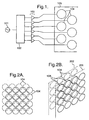
- FIG. 1 depicts a simple DPAA.
- An input signal (101) feeds a Distributor (102) whose many (6 in the drawing) outputs each connect through optional amplifiers (103) to output SETs (104) which are physically arranged to form a two-dimensional array (105).
- the Distributor modifies the signal sent to each SET to produce the desired radiation pattern. There may be additional processing steps before and after the Distributor, which are illustrated in turn later. Details of the amplifier section are shown in Figure 10.
- Figure 2 shows SETs (104) arranged to form a front Surface (201) and a second Surface (202) such that the SETs on the rear Surface radiate through the gaps between SETs in the front Surface.
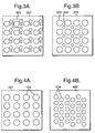
- Figure 3 shows CSETs (301) arranged to make an array (302), and two different types of SET (303, 304) combined to make an array (305).
- the "position" of the CSET may be thought to be at the centre of gravity of the group of SETS.
- Figure 4 shows two possible arrangements of SETs (104) forming a rectangular array (401) and a hex array (402).
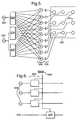
- FIG. 5 shows a DPAA with two input signals (501,502) and three Distributors (503-505).
- Distributor 503 treats the signal 501, whereas both 504 and 505 treat the input signal 502.
- the outputs from each Distributor for each SET are summed by adders (506), and pass through amplifiers 103 to the SETs 104. Details of the input section are shown in Figures 6 and 7.
- Figure 6 shows a possible arrangement of input circuitry with, for illustrative purposes, three digital inputs (601) and one analogue input (602).
- Digital receiver and analogue buffering circuitry has been omitted for clarity.
- Most current digital audio transmission formats e.g. S/PDIF, AES/EBU), DSRCs and ADCs treat (stereo) pairs of channels together. It may therefore be most convenient to handle Input Channels in pairs.
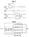
- FIG 7 shows an arrangement in which there are two digital inputs (701) which are known to be synchronous and from which the master clock is derived using a PLL or other clock recovery means (702). This situation would arise, for example, where several channels are supplied from an external surround sound decoder. This clock is then applied to the DSRCs (604) on the remaining inputs (601).
- Figure 8 shows the components of a Distributor. It has a single input signal (101) coming from the input circuitry and multiple outputs (802), one for each SET or group of SETs.
- the path from the input to each of the outputs contains a SDM (803) and/or an ADF (804) and/or an ACM (805). If the modifications made in each signal path are similar, the Distributor can be implemented more efficiently by including global SDM, ADF and/or ACM stages (806-808) before splitting the signal.
- the parameters of each of the parts of each Distributor can be varied under User or automatic control. The control connections required for this are not shown.
- the DPAA is front-back symmetrical in its radiation pattern, when beams with real focal points are formed, in the case where the array of transducers is made with an open back (ie. no sound-opaque cabinet placed around the rear of the transducers).
- additional such reflecting or scattering surfaces may advantageously be positioned at the mirror image real focal points behind the DPAA to further direct the sound in the desired manner.
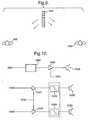
- FIG. 9 illustrates the use of an open-backed DPAA (901) to convey a signal to left and right sections of an audience (902,903), exploiting the rear radiation.
- This system may be used to detect a microphone position (see later) in which case any ambiguity can be resolved by examining the polarity of the signal received by the microphone.
- Figure 10 shows possible power amplifier configurations.
- the input digital signal (1001) possibly from a Distributor or adder, passes through a DAC (1002) and a linear power amplifier (1003) with an optional gain/volume control input (1004).
- the output feeds a SET or group of SETs (1005).
- the inputs (1006) directly feed digital amplifiers (1007) with optional global volume control input (1008).
- the global volume control inputs can conveniently also serve as the power supply to the output drive circuitry.
- the discrete-valued digital amplifier outputs optionally pass through analogue low-pass filters (1009) before reaching the SETs (1005).
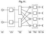
- Figure 11 shows that ONSQ stages can be incorporated in to the DPAA either before the Distributors, as (1101), or after the adders, as (1102), or in both positions. Like the other block diagrams, this shows only one elaboration of the DPAA architecture. If several elaborations are to be used at once, the extra processing steps can be inserted in any order.
- Figure 12 shows the incorporation of linear compensation (1201) and/or non-linear compensation (1202) into a single-Distributor DPAA.
- Non-linear compensation can only be used in this position if the Distributor applies only pure delay, not filtering or amplitude changes.
- Figure 13 shows, the arrangement for linear and/or non-linear compensation in a multi-Distributor DPAA.
- the linear compensation 1301 can again be applied at the input stage before the Distributors, but now each output must be separately non-linearly compensated 1302.
- This arrangement also allows non-linear compensation where the Distributor filters or changes the amplitude of the signal.
- the use of compensators allows relatively cheap transducers to be used with good results because any shortcomings can be taken into account by the digital compensation. If compensation is carried out before replication, this has the additional advantage that only one compensator per input signal is required.
- Figure 14 illustrates the interconnection of three DPAAs (1401).
- the inputs (1402), input circuitry (1403) and control systems (1404) are shared by all three DPAAs.
- the input circuitry and control system could either be separately housed or incorporated into one of the DPAAs, with the others acting as slaves.
- the three DPAAs could be identical, with the redundant circuitry in the slave DPAAs merely inactive. This set-up allows increased power, and if the arrays are placed side by side, better directivity at low frequencies.
- FIG. 15 shows the Distributor (102) of this embodiment in further detail.
- the input signal (101) is routed to a replicator (1504) by means of an input terminal (1514).
- the replicator (1504) has the function of copying the input signal a pre-determined number of times and providing the same signal at said pre-determined number of output terminals (1518).
- Each replica of the input signal is then supplied to the means (1506) for modifying the replicas.
- the means (1506) for modifying the replicas includes signal delay means (1508), amplitude control means (1510) and adjustable digital filter means (1512).
- the amplitude control means (1510) is purely optional.
- one or other of the signal delay means (1508) and adjustable digital filter (1512) may also be dispensed with.
- the most fundamental function of the means (1506) to modify replicas is to provide that different replicas are in some sense delayed by generally different amounts. It is the choice of delays which determines the sound field achieved when the output transducers (104) output the various delayed versions of the input signal (101).
- the delayed and preferably otherwise modified replicas are output from the Distributor (102) via output terminals (1516).
- each signal delay means (1508) and/or each adjustable digital filter (1512) critically influences the type of sound field which is achieved.
- the first example relates to four particularly advantageous sound fields and linear combinations thereof.
- a first sound field is shown in Figure 16A.
- the array (105) comprising the various output transducers (104) is shown in plan view. Other rows of output transducers may be located above or below the illustrated row as shown, for example, in Figures 4A or 4B.
- the delays applied to each replica by the various signal delay means (508) are set to be the same value, eg 0 (in the case of a plane array as illustrated), or to values that are a function of the shape of the Surface (in the case of curved surfaces).
- the radiation in the direction of the beam (perpendicular to the wave front) is significantly more intense than in other directions, though in general there will be "side lobes" too.
- the assumption is that the array (105) has a physical extent which is one or several wavelengths at the sound frequencies of interest. This fact means that the side lobes can generally be attenuated or moved if necessary by adjustment of the ACMs or ADFs.
- the mode of operation may generally be thought of as one in which the array (105) mimics a very large traditional loudspeaker. All of the individual transducers (104) of the array (105) are operated in phase to produce a symmetrical beam with a principle direction perpendicular to the plane of the array. The sound field obtained will be very similar to that which would be obtained if a single large loudspeaker having a diameter D was used.
- the first sound field might be thought of as a specific example of the more general second sound field.
- the delay applied to each replica by the signal delay means (1508) or adjustable digital filter (1512) is made to vary such that the delay increases systematically amongst the transducers (104) in some chosen direction across the surface of the array.
- the delays applied to the various signals before they are routed to their respective output transducer (104) may be visualised in Figure 15B by the dotted lines extending behind the transducer. A longer dotted line represents a longer delay time.
- the delays applied to the output transducers increase linearly as you move from left to right in Figure 15B.
- the signal routed to the transducer (104a) has substantially no delay and thus is the first signal to exit the array.
- the signal routed to the transducer (104b) has a small delay applied so this signal is the second to exit the array.
- the delays applied to the transducers (104c, 104d, 104e etc) successively increase so that there is a fixed delay between the outputs of adjacent transducers.
- Such a series of delays produces a roughly parallel "beam" of sound similar to the first sound field except that now the beam is angled by an amount dependent on the amount of systematic delay increase that was used.
- the beam direction will be very nearly orthogonal to the array (105); for larger delays (max t n ) - T c the beam can be steered to be nearly tangential to the surface.
- sound waves can be directed without focussing by choosing delays such that the same temporal parts of the sound waves (those parts of the sound waves representing the same information) from each transducer together form a front F travelling in a particular direction.
- the level of the side lobes (due to the finite array size) in the radiation pattern may be reduced.
- a Gaussian or raised cosine curve may be used to determine the amplitudes of the signals from each SET.
- a trade off is achieved between adjusting for the effects of finite array size and the decrease in power due to the reduced amplitude in the outer SETs.
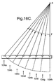
- the signal delay applied by the signal delay means (1508) and/or the adaptive digital filter (1512) is chosen such that the sum of the delay plus the sound travel time from that SET (104) to a chosen point in space in front of the DPAA are for all of the SETs the same value - ie. so that sound waves arrive from each of the output transducers at the chosen point as in-phase sounds - then the DPAA may be caused to focus sound at that point, P. This is illustrated in Figure 16C.
- the position of the focal point may be varied widely almost anywhere in front of the DPAA by suitably choosing the set of delays as previously described.
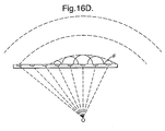
- Figure 16D shows a fourth sound field wherein yet another rationale is used to determine the delays applied to the signals routed to each output transducer.
- Huygens wavelet theorem is invoked to simulate a sound field which has an apparent origin O. This is achieved by setting the signal delay created by the signal delay means (1508) or the adaptive digital filter (1512) to be equal to the sound travel time from a point in space behind the array to the respective output transducer. These delays are illustrated by the dotted lines in Figure 16D.
- Hemispherical wave fronts are shown in Figure 16D. These sum to create the wave front F which has a curvature and direction of movement the same as a wave front would have if it had originated at the simulated origin. Thus, a true sound field is obtained.
- the method according to the first example involves using the replicator (1504) to obtain N replica signals, one for each of the N output transducers.
- Each of these replicas are then delayed (perhaps by filtering) by respective delays which are selected in accordance with both the position of the respective output transducer in the array and the effect to be achieved.
- the delayed signals are then routed to the respective output transducers to create the appropriate sound field.
- the distributor (102) preferably comprises separate replicating and delaying means so that signals may be replicated and delays may be applied to each replica.
- the distributor (102) preferably comprises separate replicating and delaying means so that signals may be replicated and delays may be applied to each replica.
- other configurations are included in the present invention, for example, an input buffer with N taps may be used, the position of the tap determining the amount of delay.
- the system described is a linear one and so it is possible to combine any of the above four effects by simply adding together the required delayed signals for a particular output transducer.
- the linear nature of the system means that several inputs may each be separately and distinctly focussed or directed in the manner described above, giving rise to controllable and potentially widely separated regions where distinct sound fields (representative of the signals at the different inputs) may be established remote from the DPAA proper. For example, a first signal can be made to appear to originate some distance behind the DPAA and a second signal can be focussed on a position some distance in front of the DPAA.
- the second example relates to the use of a DPAA not to direct or simulate the origin of sound, but to direct "anti-sound" so that quiet spots may be created in the sound field.
- Such a method can be particularly useful in a public address (PA) system which can suffer from "howl” or positive electro-acoustic feedback whenever a loudspeaker system is driven by amplified signals originating from microphones physically disposed near the loudspeakers.
- PA public address
- a loudspeaker's output reaches (often in a fairly narrow frequency band), and is picked up by, a microphone, and is then amplified and fed to the loudspeaker, and from which it again reaches the microphone ... and where the received signal's phase and frequency matches the present microphone signal's output the combined signal rapidly builds up until the system saturates, and emits a loud and unpleasant whistling, or "howling" noise.
- Anti-feedback or anti-howlround devices are known for reducing or suppressing acoustic feedback. They can operate in a number of different ways. For example, they can reduce the gain - the amount of amplification - at specific frequencies where howl-round occurs, so that the loop gain at those frequencies is less than unity. Alternatively, they can modify the phase at such frequencies, so that the loudspeaker output tends to cancel rather than add to the microphone signal.
- Another possibility is the inclusion in the signal path from microphone to loudspeaker of a frequency-shifting device (often producing a frequency shift of just a few hertz), so that the feedback signal no longer matches the microphone signal.
- the second example proposes a new way, appropriate in any situation where the microphone/loudspeaker system employs a plurality of individual transducer units arranged as an array and in particular where the loudspeaker system utilises a multitude of such transducer units as disclosed in, say, the Specification of International Patent Publication WO 96/31,086 .
- the second example suggests that the phase and/or the amplitude of the signal fed to each transducer unit be arranged such that the effect on the array is to produce a significantly reduced "sensitivity" level in one or more chosen direction (along which may actually or effectively lie a microphone) or at one or more chosen points.
- the second example proposes in one from that the loudspeaker unit array produces output nulls which are directed wherever there is a microphone that could pick up the sound and cause howl, or where for some reason it is undesirable to direct a high sound level.
- Sound waves may be cancelled (ie. nulls can be formed) by focussing or directing inverted versions of the signal to be cancelled to particular positions.
- the signal to be cancelled can be obtained by calculation or measurement.
- the method of the second example generally uses the apparatus of Figure 1 to provide a directional sound field provided by an appropriate choice of delays.
- the signals output by the various transducers (104) are inverted and scaled versions of the sound field signal so that they tend to cancel out signals in the sound field derived from the uninverted input signal.
- An example of this mechanism is shown in Figure 17.
- an input signal (101) is input to a controller (1704).
- the controller routes the input signal to a traditional loudspeaker (1702), possibly after applying a delay to the input signal.
- the loudspeaker (1702) outputs sound waves derived from the input signal to create a sound field (1706).
- the DPAA (104) is arranged to cause a substantially silent spot within this sound field at a so-called "null" position P. This is achieved by calculating the value of sound pressure at the point P due to the signal.from loudspeaker (1702). This signal is then inverted and focussed at the point P (see Figure 17) using the methods similar to focussing normal sound signals described in accordance with the first example. Almost total cancelling may be achieved by calculating or measuring the exact level of the sound field at position P and scaling the inverted signal so as to achieve more precise cancellation.
- the signal in the sound field which is to be cancelled will be almost exactly the same as the signal supplied to the loudspeaker (1702) except it will be affected by the impulse response of the loudspeaker as measured at the nulling point (it is also affected by the room acoustics, but this will be neglected for the sake of simplicity). It is therefore useful to have a model of the loudspeaker impulse response to ensure that the nulling is carried out correctly. If a correction to account for the impulse response is not used, it may in fact reinforce the signal rather than cancelling it (for example if it is 180° out of phase).
- the impulse response (the response of the loudspeaker to a sharp impulse of infinite magnitude and infinitely small duration, but nonetheless having a finite area) generally consists of a series of values represented by samples at successive times after the impulse has been applied. These values may be scaled to obtain the coefficients of an FIR filter which can be applied to the signal input to the loudspeaker (1702) to obtain a signal corrected to account for the impulse response. This corrected signal may then be used to calculate the sound field at the nulling point so that appropriate anti-sound can be beamed. The sound field at the nulling point is termed the "signal to be cancelled".
- the FIR filter mentioned above causes a delay in the signal flow, it is useful to delay everything else to obtain proper synchronisation. In other words, the input signal to the loudspeaker (1702) is delayed so that there is time for the FIR filter to calculate the sound field using the impulse response of the loudspeaker (1702).
- the impulse response can be measured by adding test signals to the signal sent to the loudspeaker (1702) and measuring them using an input transducer at the nulling point. Alternatively, it can be calculated using a model of the system.
- FIG. 18 Another form of this example is shown in Figure 18.
- the DPAA is also used for this purpose.
- the input signal is replicated and routed to each of the output transducers.
- the magnitude of the sound signal at the position P is calculated quite easily, since the sound at this position is due solely to the DPAA output. This is achieved by firstly calculating the transit time from each of the output transducers to the nulling point.
- the impulse response at the nulling point consists of the sum of each impulse response for each output transducer, delayed and filtered as the input signal will create the initial sound field, then further delayed by the transit time to the nulling point and attenuated due to 1/r 2 distance effects.
- this impulse response should be convolved (ie filtered) with the impulse response of the individual array transducers.
- the nulling signal is reproduced through those same transducers so it undergoes the same filtering at that stage. If we are using a measured (see below), rather than a model based impulse response for the nulling, then it is usually necessary to deconvolve the measured response with the impulse response of the output transducers.
- the signal to be cancelled obtained using the above mentioned considerations is inverted and scaled before being again replicated. These replicas then have delays applied to them so that the inverted signal is focussed at the position P. It is usually necessary to further delay the original (uninverted) input signal so that the inverted (nulling) signal can arrive at the nulling point at the same time as the sound field it is designed to null.
- the input signal replica and the respective delayed inverted input signal replica are added together to create an output signal for that transducer.
- the input signal (101) is routed to a first Distributor (1906) and a processor (1910). From there it is routed to an inverter (1902) and the inverted input signal is routed to a second Distributor (1908). In the first Distributor (1906) the input signal is passed without delay, or with a constant delay to the various adders (1904). Alternatively, a set of delays may be applied to obtain a directed input signal.
- the processor (1910) processes the input signal to obtain a signal representative of the sound field that will be established due to the input signal (taking into account any directing of the input signal).
- this processing will in general comprise using the known impulse response of the various transducers, the known delay time applied to each input signal replica and the known transit times from each transducer to the nulling point to determine the sound field at the nulling point.
- the second Distributor (1908) replicates and delays the inverted sound field signal and the delayed replicas are routed to the various adders (1904) to be added to the outputs from the first Distributor. A single output signal is then routed to each of the output transducers (104).
- the first distributor (1906) can provide for directional or simulated origin sound fields. This is useful when it is desired to direct a plurality of soundwaves in a particular direction, but it is necessary to have some part of the resulting field which is very quiet.
- the inverting carried out in the invertor (1902) could be carried out on each of the replicas leaving the second distributor.
- the inversion step can also be incorporated into the filter.
- the Distributor (1906) incorporates ADFs, both the initial sound field and the nulling beam can be produced by it, by summing the filter coefficients relating to the initial sound field and to the nulling beam.
- a null point may be formed within sound fields which have not been created by known apparatus if an input transducer (for example a microphone) is used to measure the sound at the position of interest.
- Figure 20 shows the implementation of such a system.
- a microphone (2004) is connected to a controller (2002) and is arranged to measure the sound level at a particular position in space.
- the controller (2002) inverts the measured signal and creates delayed replicas of this inverted signal so as to focus the inverted signal at the microphone location. This creates a negative feedback loop in respect of the sound field at the microphone location which tends to ensure quietness at the microphone location.
- this delay is tolerable.
- the signal output by the output transducers (104) of the DPAA could be filtered so as to only comprise low frequency components.
- nulling using an inverted (and possibly scaled) sound field signal which is focussed at a point.
- more general nulling could comprise directing a parallel beam using a method similar to that described with reference to the first and second sound fields of the first example.
- the advantages of the array or the invention are manifold.
- One such advantage is that sound energy may be selectively NOT directed, and so "quiet spots” may be produced, whilst leaving the energy directed into the rest of the surrounding region largely unchanged (though, as already mentioned, it may additionally be shaped to form a positive beam or beams).
- This is particularly useful in the case where the signals fed to the loudspeaker are derived totally or in part from microphones in the vicinity of the loudspeaker array: if an "anti-beam” is directed from the speaker array towards such a microphone, then the loop-gain of the system, in this direction or at this point alone, is reduced, and the likelihood of howl-round may be reduced; ie. a null or partial null is located at or near to the microphone. Where there are multiple microphones, as in common on stages, or at conferences, multiple anti-beams may be so formed and directed at each of the microphones.
- anti-beams may be directed at those boundaries to reduce the adverse effects of any reflections therefrom, thus improving the quality of sound in the listening area.
- the array-extent in one or both of the principal 2D dimensions of the transducer array is such that it is smaller than one or a few wavelengths of sound below a given frequency (Fc) within the useful range of use of the system, then its ability to produce significant directionality in either or both of those dimensions will be somewhat or even greatly reduced.
- the wavelength is very large compared to one or both of the associated dimensions, the directionality will be essentially zero.
- the array is in any case ineffective for directional purposes below frequency Fc.
- the driving signal to the transducer array should first be split into frequencies-below-frequency Fs (BandLow) and frequencies-above-Fs (BandHigh), where Fs is somewhere in the region of Fc (ie. where the array starts to interfere destructively in the far field due to its small size compared to the wavelength of signals of frequency below Fs).
- BandLow frequencies-below-frequency Fs
- BandHigh frequencies-above-Fs
- the apparatus of Figure 20 and of Figure 18 may be combined such that the input signal detected at the microphone (2004) is generally output by the transducers (104) of the DPAA but with cancellation of this output signal at the location of the microphone itself.
- the input signal detected at the microphone (2004) is generally output by the transducers (104) of the DPAA but with cancellation of this output signal at the location of the microphone itself.
- there would normally be probability of howl-round (positive electro-acoustic feedback) were the system gain to be set above a certain level. Often this limiting level is sufficiently low that users of the microphone have to be very close for adequate sensitivity, which can be problematical.
- this undesirable effect can be greatly reduced, and the system gain increased to a higher level giving more useful sensitivity.
- the present invention relates to the use of a DPAA system to create a surround sound or stereo effect using only a single sound emitting apparatus similar to the apparatus already described in relation to the first and second examples. Particularly, the present invention relates to directing different channels of sound in different directions so that the soundwaves impinge on a reflective or resonant surface and are re-transmitted thereby.
- the invention addresses the problem that where the DPAA is operated outdoors (or any other place having substantially anechoic conditions) an observer needs to move close to those regions in which sound has been focussed in order to easily perceive the separate sound fields. It is otherwise difficult for the observer to locate the separate sound fields which have been created.
- an acoustic reflecting surface or alternatively an acoustically resonant body which re-radiates.absorbed incident sound energy, is placed in such a focal region, it re-radiates the focussed sound, and so effectively becomes a new sound source, remote from the DPAA, and located at the focal region. If a plane reflector is used then the reflected sound is predominantly directed in a specific direction; if a diffuse reflector is present then the sound is re-radiated more or less in all directions away from the focal region on the same side of the reflector as the focussed sound is incident from the DPAA.
- a true multiple separated-source sound radiator system may be constructed using a single DPAA of the design described herein. It is not essential to focus sound, instead sound can be directed in the manner of the second sound field of the first example.
- the DPAA is operated in the manner previously described with multiple separated focussed beams - ie. with sound signals representative of distinct input signals focussed in distinct and separated regions - in non-anechoic conditions (such as in a normal room environment) wherein there are multiple hard and/or predominantly sound reflecting boundary surfaces, and in particular where those focussed regions are directed at one or more of the reflecting boundary surfaces, then using only his normal directional sound perceptions an observer is easily able to perceive the separate sound fields, and simultaneously locate each of them in space at their respective separate focal regions, due to the reflected sounds (from the boundaries) reaching the observer from those regions.
- the observer perceives real separated sound fields which in no way rely on the DPAA introducing artificial psycho-acoustic elements into the sound signals.
- the position of the observer is relatively unimportant for true sound location, so long as he is sufficiently far from the near-field radiation of the DPAA.
- multi-channel "surround-sound" can be achieved with only one physical loudspeaker (the DPAA), making use of the natural boundaries found in most real environments.
- Similar separated multi-source sound fields can be achieved by the suitable placement of artificial reflecting or resonating surfaces where it is desired that a sound source should seem to originate, and then directing beams at those surfaces.
- artificial reflecting or resonating surfaces where it is desired that a sound source should seem to originate, and then directing beams at those surfaces.
- optically-transparent plastic or glass panels could be placed and used as sound reflectors with little visual impact.
- a sound scattering reflector or broadband resonator could be introduced instead (this would be more difficult but not impossible to make optically transparent).
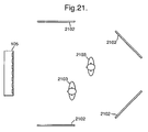
- Figure 21 illustrates the use of a single DPAA and multiple reflecting or resonating surfaces (2102) to present multiple sources to listeners (2103). As it does not rely on psychoacoustic cues, the surround sound effect is audible throughout the listening area.
- a spherical reflector having a diameter roughly equivalent to the size of the focus point can be used to achieve diffuse reflection over a wide angle.
- the surfaces should have a roughness on the scale of the wavelength of sound frequency it is desired to diffuse.
- the invention can be used in conjunction with the second example to provide that anti-beams of the other channels may be directed towards the reflector associated with a given channel.
- channel 1 may be focussed at reflector 1 and channel 2 may be focussed at reflector 2 and appropriate nulling would be included to null channel I at reflector 2 and null channel 2 at reflector 1. This would ensure that only the correct channels have significant energy at the respective reflective surface.
- the great advantage of the present invention is that all of the above may be achieved with a single DPAA apparatus, the output signals for each transducer being built up from summations of delayed replicas of (possibly corrected and inverted) input signals.
- much wiring and apparatus traditionally associated with surround sound systems is dispensed with.
- the third example relates to the use of microphones (input transducers) and test signals to locate the position of a microphone in the vicinity of an array of output transducers or the position of a loudspeaker in the vicinity of an array of microphones.
- one or more microphones are provided that are able to sense the acoustic emission from the DPAA, and which are connected to the DPAA control electronics either by wired or wireless means.
- the DPAA incorporates a subsystem arranged to be able to compute the location of the microphone(s) relative to one or more DPAA SETs by measuring the propagation times of signals from three or more (and in general from all of the) SETs to the microphone and triangulating, thus allowing the possibility of tracking the microphone movements during use of the DPAA without interfering with the listener's perception of the programme material sound.
- the DPAA SET array is open-backed - ie. it radiates from both sides of the transducer in a dipole like manner - the potential ambiguity of microphone position, in front of or behind the DPAA, may be resolved by examination of the phase of the received signals (especially at the lower frequencies).
- the speed of sound which changes with air temperature during the course of a performance, affecting the acoustics of the venue and the performance of the speaker system, can be determined in the same process by using an additional triangulation point.
- the microphone locating may either be done using a specific test pattern (eg. a pseudo-random noise sequence or sequence of short pulses to each of the SETs in turn, where the pulse length t p is as short or shorter than the spatial resolution r s required, in the sense that t p ⁇ r, / c s ) or by introducing low level test signals (which may be designed to be inaudible) with the programme material being broadcast by the DPAA, and then detecting these by cross-correlation.
- a specific test pattern eg. a pseudo-random noise sequence or sequence of short pulses to each of the SETs in turn, where the pulse length t p is as short or shorter than the spatial resolution r s required, in the sense that t p ⁇ r
- a control system may be added to the DPAA that optimises (in some desired sense) the sound field at one or more specified locations, by altering the delays applied by the SDMs and/or the filter coefficients of the ADFs. If the previously described microphones are available, then this optimisation can occur either at set-up time - for instance during pre-performance use of the DPAA) - or during actual use. In the latter case, one or more of the microphones may be embedded in the handset used otherwise to control the DPAA, and in this case the control system may be designed actively to track the microphone in real-time and so continuously to optimise the sound at the position of the handset, and thus at the presumed position of at least one of the listeners.
- control system may use this model to estimate automatically the required adjustments to the DPAA parameters to optimise the sound at any user-specified positions to reduce any troublesome side lobes.
- the control system just described can additionally be made to adjust the sound level at one or more specific locations - eg. positions where live performance microphones are situated, which are connected to the DPAA, or positions where there are known to be undesired reflecting surfaces - to be minimised, creating "dead-zones". In this way unwanted mic/DPAA feedback can be avoided, as can unwanted room reverberations. This possibility has been discussed in the section relating to the second aspect of the invention.
- one or more of the live performance microphones can be spatially tracked (by suitable processing of the pattern of delays between said microphones and the DPAA transducers).
- This microphone spatial information may in turn be used for purposes such as positioning the "dead-zones" wherever the microphones are moved to (note that the buried test-signals will of necessity be of non-zero amplitude at the microphone positions).
- Figure 22 illustrates a possible configuration for the use of a microphone to specify locations in the listening area.
- the microphone (2201) is connected an analogue or digital input (2204) of the DPAA (105) via a radio transmitter (2202) and receiver (2203).
- a wired or other wirefree connection could instead be used if more convenient.
- Most of the SETs (104) are used for normal operation or are silent.
- a small number of SETs (2205) emit test signals, either added to or instead of the usual programme signal.
- the path lengths (2206) between the test SETs and the microphone are deduced by comparison of the test signals and microphone signal, and used to deduce the location of the microphone by triangulation. Where the signal to noise ratio of the received test signals is poor, the response can be integrated over several seconds.
- FIG. 23 illustrates this problem.
- the area 2302 surrounded by the dotted line indicates the sound field shape of the DPAA (105) in the absence of wind. Wind W blows from the right so that the sound field 2304 is obtained, which is a skewed version of field 2302.
- the propagation of the microphone location finding signals are affected in the same manner by crosswinds.
- the wind W causes the test signals to take a curved path from the DPAA to the microphone. This causes the system to erroneously locate the microphone at position P, west of the true position M.
- the radiation pattern of the array way is adjusted to optimise coverage around the apparent microphone location P, to compensate for the wind, and give optimum coverage in the actual audience area.
- the DPAA control system can make these adjustments automatically during the course of a performance. To ensure stability of the control system, only slow changes must be made. The robustness of the system can be improved using multiple microphones at known locations throughout the audience area. Even when the wind changes, the sound field can be kept substantially constantly directed in the desired way.
- the use of the microphones previously described allows a simple way to set up this situation.
- One of the microphones is temporarily positioned near the surface which is to become the remote sound source, and the position of the microphone is accurately determined by the DPAA sub-system already described.
- the control system then computes the optimum array parameters to locate a focussed or directed beam (connected to one or more of the user-selected inputs) at the position of the microphone. Thereafter the microphone may be removed.
- the separate remote sound source will then emanate from the surface at the chosen location.
- the time it takes the test signal to travel from each output transducer to the input transducer may generally be calculated for all of the output transducers in the array giving rise to many more simultaneous equations than there are variables to be solved (three spatial variables and the speed of sound). Values for the variables which yield the lowest overall error can be obtained by appropriate solving of the equations.
- test signals may comprise pseudo-random noise signals or inaudible signals which are added to delayed input signal replicas being output by the DPAA SETs or are output via transducers which do not output any input signal components.
- the system according to the third example is also applicable to a DPAA apparatus made up of an array of input transducers with an output transducer in the vicinity of that array.
- the output transducer can output only a single test signal which will be received by each of the input transducers in the array.
- the time between output of the test signal and its reception can then be used to triangulate the position of the output transducer and/or calculate the speed of sound.
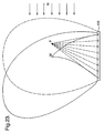
- Figs. 24 to 26 illustrate how such input nulls are set up. Firstly, the position O at which an input null should be located is selected. At this position, it should be possible to make noises which will not be picked up by the array of input transducers (2404) as a whole. The method of creating this input null will be described by referring to an array having only three input transducers (2404a, 2404b and 2404c), although many more would be used in practice.
- transducer (2404c) the situation in which sound is emitted from a point source located at position O is considered. If a pulse of sound is emitted at time 0, it will reach transducer (2404c) first, then transducer (2404b) and then transducer (2404a) due to the different path lengths. For ease of explanation, we will assume that the pulse reaches transducer (2404c) after 1 second, transducer (2404b) after 1.5 seconds and transducer (2404a) after 2 seconds (these are unrealistically large figures chosen purely for ease of illustration). This is shown in Figure 25A. These received input signals are then delayed by varying amounts so as to actually focus the input sensitivity of the array on the position 0.
- this involves delaying the input received at transducer (2404b) by 0.5 seconds and the input received at transducer (2404c) by 1 second. As can be seen from Figure 25B, this results in modifying all of the input signals (by applying delays) to align in time. These three input signals are then summed to obtain an output signal as shown in Figure 25C. The magnitude of this output signal is then reduced by dividing the output signal by approximately the number of input transducers in the array. In the present case, this involves dividing the output signal by three to obtain the signal shown in Figure 25D. The delays applied to the various input signals to achieve the signals shown in Figure 25B are then removed from replicas of the output signal.
- the output signal is replicated and advanced by varying amounts which are the same as the amount of delay that was applied to each input signal. So, the output signal in Figure 25D is not advanced at all to create a first nulling signal Na. Another replica of the output signal is advanced by 0.5 seconds to create nulling signal Nb and a third replica of the output signal is advanced by 1 second to create nulling signal Nc. The nulling signals are shown in Figure 25E.
- these nulling signals are subtracted from the respective input signals to provide a series of modified input signals.
- the nulling signals in the present example are exactly the same as input signals and so three modified signals having substantially zero magnitude are obtained.
- the input nulling method of the third example serves to cause the DPAA to ignore signals emitted from position O where an input null is located.
- the pulse level will in general be reduced by (N-1)/(N) of a pulse and the noise will in general have a magnitude of(1/N) of a pulse.
- the effect of the modification is negligible when the sound comes from a point distal from the nulling position O.
- the signals of 26F can then be used for conventional beamforming to recover the signal from X.
- the various test signals used with the third example are distinguishable by applying a correlation function to the various input signals.
- the test signal to be detected is cross-correlated with any input signal and the result of such cross-correlation is analysed to indicate whether the test signal is present in the input signal.
- the pseudo-random noise signals are each independent such that no one signal is a linear combination of any number of other signals in the group. This ensures that the cross-correlation process identifies the test signals in question.
- the test signals may desirably be formulated to have a non-flat spectrum so as to maximise their inaudibility. This can be done by filtering pseudo-random noise signals. Firstly, they may have their power located in regions of the audio band to which the ear is relatively insensitive. For example, the ear has most sensitivity at around 3.5KHz so the test signals preferably have a frequency spectrum with minimal power near this frequency. Secondly, the masking effect can be used by adaptively changing the test signals in accordance with the programme signal, by putting much of the test signal power in parts of the spectrum which are masked.
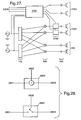
- Figure 27 shows a block diagram of the incorporation of test signal generation and analysis into a DPAA.
- Test signals are both generated and analysed in block (2701). It has as inputs the normal input channels 101, in order to design test signals which are imperceptible due to a masking by the desired audio signal, and microphone inputs 2204.
- the usual input circuitry, such as DSRCs and/or ADCs have been omitted for clarity.
- the test signals are emitted either by dedicated SETs (2703) or shared SETs 2205. In the latter case the test signal is incorporated into the signal feeding each SET in a test signal insertion step (2702).
- Figure 28 shows two possible test signal insertion steps.
- the programme input signals (2801) come from a Distributor or adder.
- the test signals (2802) come from block 2701 in Figure 27.
- the output signals (2803) go to ONSQs, non-linear compensators, or directly to amplifier stages.
- insertion step (2804) the test signal is added to the programme signal.
- insertion step (2805) the test signal replaces the programme signal. Control signals are omitted.
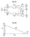
- Figure 29 illustrates the general apparatus for selectively beaming distinct frequency bands.
- Input signal 101 is connected to a signal splitter/combiner (2903) and hence to a low-pass-filter (2901) and a high-pass-filter (2902) in parallel channels.
- Low-pass-filter (2901) is connected to a Distributor (2904) which connects to all the adders (2905) which are in turn connected to the N transducers (104) of the DPAA (105).
- High-pass-filter (2902) connects to a device (102) which is the same as device (102) in Figure 2 (and which in general contains within it N variable-amplitude and variable-time delay elements), which in turn connects to the other ports of the adders (2905).
- the system may be used to overcome the effect of far-field cancellation of the low frequencies, due to the array size being small compared to a wavelength at those lower frequencies.
- the system therefore allows different frequencies to be treated differently in terms of shaping the sound field.
- the lower frequencies pass between the source/detector and the transducers (2904) all with the same time-delay (nominally zero) and amplitude, whereas the higher frequencies are appropriately time-delayed and amplitude-controlled for each of the N transducers independently. This allows anti-beaming or nulling of the higher frequencies without global far-field nulling of the low frequencies.
- the method according to the fourth example can be carried out using the adjustable digital filters (512).
- Such filters allow different delays to be accorded to different frequencies by simply choosing appropriate values for the filter coefficients. In this case, it is not necessary to separately split up the frequency bands and apply different delays to the replicas derived from each frequency band. An appropriate effect can be achieved simply by filtering the various replicas of the single input signal.
- the fifth example addresses the problem that a user of the DPAA system may not always be easily able to locate where sound of a particular channel is being focussed at any particular time.
- This problem is alleviated by providing two steerable beams of light which can be caused to cross in space at the point where sound is being focussed.
- the beams of light are under the control of the operator and the DPAA controller is arranged to cause sound channel focussing to occur wherever the operator causes the light beams to intersect. This provides a very easy to set up system which does not rely on creating mathematical models of the room or other complex calculations.
- two light beams may be steered automatically by the DPAA electronics such that they intersect in space at or near the centre of the focal region of a channel, again providing a great deal of useful set-up feedback information to the operator.
- Means to select which channel settings control the positions of the light beams should also be provided and these may all be controlled from the handset.
- the focal regions of multiple channels may be high-lighted simultaneously by the intersection locations in space of pairs of the steerable light beams.
- Small laser beams particularly solid-state diode lasers, provide a useful source of collimated light.
- Steering is easily achieved through small steerable mirrors driven by galvos or motors, or alternatively by a WHERM mechanism as described in the specification of the British Patent Application No. 0003,136.9 .
- Figure 30 illustrates the use of steerable light beams (3003, 3004) emitted from projectors (3001, 3002) on a DPAA to show the point of focus (3005). If projector (3001) emits red light and (3002) green light, then yellow light will be seen at the point of focus.
- a digital peak limiter is a system which scales down an input digital audio signal as necessary to prevent the output signal from exceeding a specified maximum level. It derives a control signal from the input signal, which may be subsampled to reduce the required computation. The control signal is smoothed to prevent discontinuities in the output signal. The rate at which the gain is decreased before a peak (the attack time constant) and returned to normal afterwards (the release time constant) are chosen to minimise the audible effects of the limiter. They can be factory-preset, under the control of the user, or automatically adjusted according to the characteristics of the input signal. If a small amount of latency can be tolerated, then the control signal can "look ahead" (by delaying the input signal but not the control signal), so that the attack phase of the limiting action can anticipate a sudden peak.
- each SET receives sums of the input signals with different relative delays, it is not sufficient simply to derive the control signal for a peak limiter from a sum of the input signals, as peaks which do not coincide in one sum may do so in the delayed sums presented to one or more SETs. If independent peak limiters are used on each summed signal then, when some SETs are limited and others are not, the radiation pattern of the array will be affected.
- MML Multichannel Multiphase Limiter
- This apparatus acts on the input signals. It finds the peak level of each input signal in a time window spanning the range of delays currently implemented by the SDMs, then sums these I peak levels to produce its control signal. If the control signal does not exceed the FSDL, then none of the delayed sums presented to individual SETs can, so no limiting action is required. If it does, then the input signals should be limited to bring the level down to the FSDL.
- the attack and release time constants and the amount of lookahead can be either under the control of the user or factory-preset according to application.
- the MML can act either before or after the oversampler.
- Lower latency can be achieved by deriving the control signal from the input signals before oversampling, then applying the limiting action to the oversampled signals; a lower order, lower group delay anti-imaging filter can be used for the control signal, as it has limited bandwidth.
- Figure 31 illustrates a two-channel implementation of the MML although it can be extrapolated for any number of channels (input signals).
- the input signals (3101) come from the input circuitry or the linear compensators.
- the output signals (3111) go to the Distributors.
- Each delay unit (3102) comprises a buffer and stores a number of samples of its input signal and outputs the maximum absolute value contained in its buffer as (3103). The length of the buffer can be changed to track the range of delays implemented in the distributors by control signals which are not illustrated.
- the adder (3104) sums these maximum values from each channel. Its output is converted by the response shaper (3105) into a more smoothly varying gain control signal with specified attack and release rates.
- the input signals are each attenuated in accordance with the gain control signal.
- the signals are attenuated in proportion to the gain control signal.
- Delays (3109) may be incorporated into the channel signal paths in order to allow gain changes to anticipate peaks.
- oversampling If oversampling is to be incorporated, it can be placed within the MML, with upsampling stages (3106) followed by anti-image filters (3107-3108). High quality anti-image filters can have considerable group delay in the passband. Using a filter design with less group delay for 3108 can allow the delays 3109 to be reduced or eliminated.
- the MML is most usefully incorporated after them in the signal path, splitting the Distributors into separate global and per-SET stages.
- the sixth example therefore allows a limiting device which is simple in construction, which effectively prevents clipping and distortion and which maintains the required radiation shaping.
- the seventh example relates to the method for detecting, and mitigating against the effects of, failed transducers in an array.
- the method according to the seventh example requires that a test signal is routed to each output transducer of the array which is received (or not) by an input transducer located nearby, so as to determine whether a transducer has failed.
- the test signals may be output by each transducer in turn or simultaneously, provided that the test signals are distinguishable from one another.
- the test signals are generally similar to those used in relation to the third example already described.
- the failure detection step may be carried out initially before setting up a system, for example during a "sound check” or, advantageously, it can be carried out all the time the system is in use, by ensuring that the test signals are inaudible or not noticeable. This is achieved by providing that the test signals comprise pseudo-random noise signals of low amplitude. They can be sent by groups of transducers at a time, these groups changing so that eventually all the transducers send a test signal, or they can be sent by all of the transducers for substantially all of the time, being added to the signal which it is desired to output from the DPAA.
- transducer failure If a transducer failure is detected, it is often desirable to mute that transducer so as to avoid unpredictable outputs. It is then further desirable to reduce the amplitude of output of the transducers adjacent to the muted transducer so as to provide some mitigation against the effect of a failed transducer. This correction may extend to controlling the amplitude of a group of working transducers located near to a muted transducer.
- the eighth example relates to a method for reproducing an audio signal received at a reproducing device such as a DPAA which steers the audio output signals so that they are transmitted mainly in one or a plurality of separate directions.
- the amount of delay observed at each transducer determines the direction in which the audio signal is directed. It is therefore necessary for an operator of such a system to program the device so as to direct the signal in a particular direction. If the desired direction changes, it is necessary to reprogram the device.
- the eighth example seeks to alleviate the above problem by providing a method and apparatus which can direct an output audio signal automatically.
- the associated information signal is decoded and is used to shape the sound field. This dispenses with the need for an operator to program where the audio signal must be directed and also allows the direction of audio signal steering to be changed as desired during reproduction of the audio signal.
- the eighth example is a sound playback system capable of reproducing one or several audio channels, some or all of which of these channels have an associated stream of time-varying steering information, and a number of loudspeaker feeds.
- Each stream of steering information is used by a decoding system to control how the signal from the associated audio channel is distributed among the loudspeaker feeds.
- the number of loudspeaker feeds is typically considerably greater than the number of recorded audio channels and the number of audio channels used may change in the course of a programme.
- the eighth example applies mainly to reproducing systems which can direct sound in one of a number of directions. This can be done in a plurality of ways:-
- most of the loudspeaker feeds drive a large, two-dimensional array of loudspeakers, forming a phased array.
- the eighth example comprises associating sound field shaping information with the actual audio signal itself, the shaping information being useable to dictate how the audio signal will be directed.
- the shaping information can comprise one or more physical positions on which it is desired to focus a beam or at which it is desired to simulate the sound origin.
- the steering information may consist of the actual delays to be provided to each replica of the audio signal.
- this approach leads to the steering signal comprising a lot of information.
- the steering information is preferably multiplexed into the same data stream as the audio channels.
- They can be combined into an MPEG stream and delivered by DVD, DVB, DAB or any future transport layer.
- the conventional digital sound systems already present in cinemas could be extended to use the composite signal.
- steering information which consists of gains, delays and filter coefficients for each loudspeaker feed
- the decoding system is programmed with, or determines by itself, the location of the loudspeaker(s) driven by each loudspeaker feed and the shape of the listening area. It uses this information to derive the gains, delays and filter coefficients necessary to make each channel come from the location described by the steering information.
- This approach to storing the steering information allows the same recording to be used with different speaker and array configurations and in differently sized spaces. It also significantly reduces the quantity of steering information to be stored or transmitted.
- the array In audio-visual and cinema applications, the array would typically be located behind the screen (made of acoustically transparent material), and be a significant fraction of the size of the screen.
- the use of such a large array allows channels of sound to appear to come from any point behind the screen which corresponds to the locations of objects in the projected image, and to track the motion of those objects.
- Encoding the steering information using units of the screen height and width, and informing the decoding system of the location of the screen will then allow the same steering information to be used in cinemas with different sized screens, while the apparent audio sources remain in the same place in the image.
- the system may be augmented with discrete (non-arrayed) loudspeakers or extra arrays. It may be particularly convenient to place an array on the ceiling.
- Figure 32 shows a device for carrying out the method.
- An audio signal multiplexed with an information signal is input to the terminal 3201 of the de-multiplexer 3207.
- the de-multiplexer 3207 outputs the audio signal and the information signal separately.
- the audio signal is routed to input terminal 3202 of decoding device 3208 and the information signal is routed to terminal 3203 of the decoding device 3208.
- the replicating device 3204 replicates the audio signal input at input terminal 3202 into a number of identical replicas (here, four replicas are used, but any number is possible).
- the replicating device 3204 outputs four signals each identical to the signal presented at input terminal 3202.
- the information signal is routed from terminal 3203 to a controller 3209 which is able to control the amount of delay applied to each of the replicated signals at each of the delay elements 3210.
- Each of the delayed replicated audio signals are then sent to separate transducers 3206 via output terminal 3205 to provide a directional sound output.
- the information comprising the information signal input at the terminal 3203 can be continuously changed with time so that the output audio signal can be directed around the auditorium in accordance with the information signal. This prevents the need for an operator to continuously monitor the audio signal output direction to provide the necessary adjustments.
- the information signal input to terminal 3203 can comprise values for the delays that should be applied to the signal input to each transducer 3206.
- the information stored in the information signal could instead comprise physical location information which is decoded in the decoder 3209 into an appropriate set of delays. This may be achieved using a look-up table which maps physical locations in the auditorium with a set of delays to achieve directionality to that location.
- a mathematical algorithm such as that provided in the description of the first aspect of the invention, is used which translates a physical location into a set of delay values.
- the eighth example also comprises a decoder which can be used with conventional audio playback devices so that the steering information can be used to provide traditional stereo sound or surround sound.
- the steering information can be used to synthesize a binaural representation of the recording using head-related transfer functions to position apparent sound sources around the listener.
- a recorded signal comprising the audio channels and associated steering information can be played back in a conventional manner if desired, say, because no phased array is available.
- the above description refers to a system using a single audio input which is played back through all of the transducers in the array.
- the system may be extended to play back multiple audio inputs (again, using all of the transducers) by processing each input separately and thus calculating a set of delay coefficients for each input (based on the information signal associated with that input) and summing the delayed audio inputs obtained for each transducer.
- This is possible due to the linear nature of the system. This allows separate audio inputs to be directed in different ways using the same transducers. Thus many audio inputs can be controlled to have directivity in particular directions which change throughout a performance automatically.
- the ninth example relates to a method of designing a sound field output by a DPAA device.
- ADFs allows a constrained optimisation procedure many degrees of freedom.
- a user would specify targets, typically areas of the venue in which coverage should be as even as possible, or should vary systematically with distance, other regions in which coverage should be minimised, possibly at particular frequencies, and further regions in which coverage does not matter.
- the regions can be specified by the use of microphones or another positioning system, by manual user input, or through the use of data sets from architectural or acoustic modelling systems.
- the targets can be ranked by priority.
- the optimisation procedure can be carried out either by within the DPAA itself, in which case it could be made adaptive in response to wind variations, as described above, or as a separate step using an external computer.
- the optimisation comprises selecting appropriate coefficients for the ADFs to achieve the desired effect. This can.be done, for example, by starting with filter coefficients equivalent to a single set of delays as described in the first example, and calculating the resulting radiation pattern through simulation. Further positive and negative beams (with different, appropriate delays) can then be added iteratively to improve the radiation pattern, simply by adding their corresponding filter coefficients to the existing set.
Claims (52)
- Procédé pour faire apparaître plusieurs signaux d'entrée représentant des canaux respectifs comme émanant de positions différentes respectives dans l'espace, ledit procédé comprenant les étapes consistant à :prévoir une surface réfléchissant les sons ou résonante en chacune desdites positions dans l'espace ;prévoir un ensemble de transducteurs de sortie distants desdites positions dans l'espace ; etdiriger, en employant ledit ensemble de transducteurs de sortie, les ondes sonores de chaque canal vers la position respective dans l'espace pour que lesdites ondes sonores soient retransmises par ladite surface réfléchissante ou résonante ;ladite étape de direction comprenant les opérations consistant à :obtenir, relativement à chaque transducteur, une réplique retardée de chaque signal d'entrée retardé d'un retard respectif choisi selon la position dans l'ensemble du transducteur de sortie respectif et de ladite position respective dans l'espace de telle manière que les ondes sonores du canal sont dirigées vers la position dans l'espace relativement à ce canal ;additionner, relativement à chaque transducteur, les répliques retardées respectives de chaque signal d'entrée pour produire un signal de sortie ; etacheminer les signaux de sortie jusqu'aux transducteurs respectifs.
- Procédé selon la revendication 1, dans lequel ladite étape d'obtention, relativement à chaque transducteur de sortie, d'une réplique retardée du signal d'entrée comprend :la réplication dudit signal d'entrée ledit nombre de fois prédéterminé pour obtenir un signal réplique relativement à chaque transducteur de sortie ;retarder chaque réplique dudit signal d'entrée par ledit retard respectif choisi selon la position dans l'ensemble du transducteur de sortie respectif et ladite position respective dans l'espace.
- Procédé selon la revendication 1 ou 2, comprenant en outre :le calcul, avant ladite étape de retard, des retards respectifs relativement à chaque réplique du signal d'entrée par les opérations consistant à :déterminer la distance qui sépare chaque transducteur de sortie de la position dans l'espace par rapport à ce signal d'entrée ;déduire des valeurs de retard respectives telles que les ondes sonores provenant de chaque transducteur pour un seul canal arrivent simultanément à ladite position dans l'espace.
- Procédé selon l'une quelconque des revendications 1 à 3, comprenant en outre les opérations consistant à :inverser l'un desdits signaux d'entrée ;obtenir, relativement à chaque transducteur de sortie, une réplique retardée dudit signal d'entrée inversé retardé d'un retard respectif choisi selon la position dans l'ensemble du transducteur respectif, de sorte que les ondes sonores obtenues à partir dudit signal d'entrée inversé sont dirigées en une position dans l'espace afin d'annuler au moins partiellement les ondes sonores obtenues à partir de ce signal d'entrée à cette position dans l'espace.
- Procédé selon la revendication 4, dans lequel ladite étape d'obtention, relativement à chaque transducteur de sortie, d'une réplique retardée dudit signal d'entrée inversé comprend :la réplication dudit signal d'entrée inversé ledit nombre de fois prédéterminé pour obtenir un signal réplique relativement à chaque transducteur de sortie ;retarder chaque réplique dudit signal d'entrée inversé par un retard prédéterminé respectif choisi selon la position dans l'ensemble du transducteur de sortie respectif.
- Procédé selon la revendication 4 ou 5, dans lequel ledit signal d'entrée inversé est réduit de sorte que les ondes sonores obtenues à partir dudit signal d'entrée inversé annulent substantiellement les ondes sonores obtenues à partir de ce signal d'entrée à ladite position dans l'espace.
- Procédé selon la revendication 6, dans lequel ladite réduction est choisie en déterminant, relativement au signal d'entrée qui a été inversé, l'amplitude des ondes sonores à ladite position dans l'espace et en choisissant ladite réduction de telle manière que les ondes sonores obtenues à partir dudit signal d'entrée inversé ont sensiblement la même amplitude en cette position.
- Procédé selon l'une quelconque des revendications 1 à 7, dans lequel au moins l'une desdites surfaces est fournie par un mur d'une pièce ou autre structure permanente.
- Procédé selon l'une quelconque des revendications 1 à 8, dans lequel ledit ensemble de transducteurs de sortie comprend un motif régulier de transducteurs de sortie dans un plan en deux dimensions.
- Procédé selon la revendication 9, dans lequel chacun desdits transducteurs de sortie a une direction de sortie principale perpendiculaire audit plan en deux dimensions.
- Procédé selon la revendication 9 ou 10, dans lequel ledit plan en deux dimensions est un plan courbé.
- Procédé selon l'une quelconque des revendications 1 à 11, dans lequel chacun desdits transducteurs de sortie est commandé par un amplificateur de puissance numérique.
- Procédé selon l'une quelconque des revendications 1 à 12, dans lequel l'amplitude d'un signal délivré par un transducteur dudit ensemble de transducteurs de sortie est commandée de façon à modeler de manière plus précise le champ sonore.
- Procédé selon l'une quelconque des revendications 1 à 13, dans lequel les signaux sont suréchantillonnés avant d'être retardés.
- Procédé selon l'une quelconque des revendications 1 à 14, dans lequel les signaux sont modelés par du bruit avant d'être répliqués.
- Procédé selon l'une quelconque des revendications 1 à 15, dans lequel les signaux sont convertis en signaux MLI avant d'être acheminés jusqu'aux transducteurs de sortie respectifs de l'ensemble.
- Procédé selon la revendication 13, dans lequel ladite commande est prévue pour réduire l'amplitude de signaux de sortie transmis à des transducteurs autour de la périphérie de l'ensemble.
- Procédé selon la revendication 13 ou 17, dans lequel ladite commande est prévue pour réduire l'amplitude de signaux de sortie transmis à des transducteurs selon une fonction prédéterminée comme une courbe de Gauss ou une courbe de cosinus carré.
- Procédé selon l'une quelconque des revendications 1 à 18, dans lequel chacun desdits transducteurs comprend un groupe de transducteurs individuels.
- Procédé selon l'une quelconque des revendications 1 à 19, dans lequel des compensateurs linéaires ou non linéaires sont placés avant chaque transducteur de sortie pour ajuster un signal acheminé jusqu'à celui-ci pour prendre en compte les imperfections du transducteur de sortie.
- Procédé selon la revendication 20, dans lequel ledit compensateur est un compensateur linéaire prévu pour compenser un signal de sortie avant qu'il soit répliqué.
- Procédé selon la revendication 20 ou 21, dans lequel lesdits compensateurs sont adaptables en fonction de la forme du champ sonore, de sorte que les composantes à haute fréquence sont amplifiées selon l'angle suivant lequel elles doivent être orientées.
- Procédé selon l'une quelconque des revendications 1 à 22, dans lequel des moyens sont prévus pour commander progressivement les changements du champ sonore.
- Procédé selon la revendication 23, dans lequel lesdits moyens fonctionnent de telle manière qu'un retard de signal est augmenté progressivement en dupliquant des échantillons ou bien diminué progressivement en sautant des échantillons.
- Procédé selon l'une quelconque des revendications 1 à 24, dans lequel la directivité du champ sonore est changée sur la base du signal transmis au système et délivré en sortie de l'ensemble de transducteurs de sortie.
- Procédé selon l'une quelconque des revendications 1 à 25, dans lequel il est prévu plusieurs ensembles de transducteurs de sortie, qui sont commandés par un dispositif de commande commun.
- Appareil destiné à faire apparaître plusieurs signaux d'entrée représentant des canaux respectifs comme émanant de positions différentes respectives dans l'espace, à utiliser avec des surfaces réfléchissantes ou résonantes en chacune desdites positions dans l'espace, ledit appareil comprenant :un ensemble de transducteurs de sortie distants desdites positions dans l'espace ; etun dispositif de commande pour diriger, en employant ledit ensemble de transducteurs de sortie, les ondes sonores de chaque canal vers la position respective de ce canal dans l'espace de telle manière que lesdites ondes sonores sont retransmises par ladite surface réfléchissante ou résonante ;ledit dispositif de commande comprenant :un moyen de réplication et de retard prévu pour obtenir, relativement à chaque transducteur, une réplique retardée du signal d'entrée retardé d'un retard respectif choisi selon la position dans l'ensemble du transducteur de sortie respectif et ladite position respective dans l'espace de telle manière que les ondes sonores du canal sont dirigées vers la position dans l'espace relativement à ce signal d'entrée ;un moyen additionneur prévu pour additionner, relativement à chaque transducteur, les répliques retardées respectives de chaque signal d'entrée pour produire un signal de sortie ; etun moyen pour acheminer les signaux de sortie jusqu'aux transducteurs respectifs de telle manière que les ondes sonores des canaux sont dirigées vers la position dans l'espace relativement à ce signal d'entrée.
- Appareil selon la revendication 27, dans lequel ledit dispositif de commande comprend en outre :un moyen de calcul pour calculer les retards respectifs relativement à chaque réplique du signal d'entrée par les opérations consistant à :déterminer la distance qui sépare chaque transducteur de sortie de la position dans l'espace par rapport à ce signal d'entrée ;déduire des valeurs de retard respectives telles que les ondes sonores provenant de chaque transducteur pour un seul canal arrivent simultanément à ladite position dans l'espace.
- Appareil selon la revendication 27 ou 28, dans lequel ledit dispositif de commande comprend en outre :un inverseur pour inverser l'un desdits signaux d'entrée ;un deuxième moyen de réplication et de retard prévu pour obtenir, relativement à chaque transducteur de sortie, une réplique retardée dudit signal d'entrée inversé retardé d'un retard respectif choisi selon la position dans l'ensemble du transducteur respectif et une deuxième position dans l'espace, de sorte que les ondes sonores obtenues à partir dudit signal d'entrée inversé sont dirigées en ladite deuxième position dans l'espace afin d'annuler au moins partiellement les ondes sonores obtenues à partir de ce signal d'entrée à ladite deuxième position dans l'espace.
- Appareil selon la revendication 29, dans lequel ledit dispositif de commande comprend en outre un dispositif de réduction pour réduire ledit signal d'entrée inversé de sorte que les ondes sonores obtenues à partir dudit signal d'entrée inversé annulent substantiellement les ondes sonores obtenues à partir de ce signal d'entrée à ladite deuxième position dans l'espace.
- Appareil selon l'une quelconque des revendications 27 à 30, comprenant de plus une surface réfléchissant les sons ou résonante en chacune desdites positions dans l'espace.
- Appareil selon l'une quelconque des revendications 27 à 31, dans lequel lesdites surfaces sont réfléchissantes et ont une rugosité située sur l'échelle de la longueur d'onde de fréquence sonore que l'on souhaite réfléchir de manière diffuse.
- Appareil selon l'une quelconque des revendications 27 à 32, dans lequel lesdites surfaces sont optiquement transparentes.
- Appareil selon l'une quelconque des revendications 27 à 33, dans lequel au moins l'une desdites surfaces est un mur d'une pièce ou autre structure permanente.
- Appareil selon l'une quelconque des revendications 27 à 34, dans lequel ledit ensemble de transducteurs de sortie comprend un motif régulier de transducteurs de sortie dans un plan en deux dimensions.
- Appareil selon la revendication 35, dans lequel chacun desdits transducteurs de sortie a une direction de sortie principale perpendiculaire audit plan en deux dimensions.
- Appareil selon la revendication 34 ou 36, dans lequel ledit plan en deux dimensions est un plan courbé.
- Appareil selon l'une quelconque des revendications 27 à 37, dans lequel chacun desdits transducteurs de sortie est commandé par un amplificateur de puissance numérique.
- Appareil selon l'une quelconque des revendications 27 à 38, dans lequel l'amplitude d'un signal délivré par un transducteur dudit ensemble de transducteurs de sortie est commandée de façon à modeler de manière plus précise le champ sonore.
- Appareil selon l'une quelconque des revendications 27 à 39, dans lequel les signaux sont suréchantillonnés avant d'être retardés.
- Appareil selon l'une quelconque des revendications 27 à 40, dans lequel les signaux sont modelés par du bruit avant d'être répliqués.
- Appareil selon l'une quelconque des revendications 27 à 41, dans lequel les signaux sont convertis en signaux MLI avant d'être acheminés jusqu'aux transducteurs de sortie respectifs de l'ensemble.
- Appareil selon la revendication 39, dans lequel ladite commande est prévue pour réduire l'amplitude de signaux de sortie transmis à des transducteurs autour de la périphérie de l'ensemble.
- Appareil selon la revendication 39 ou 43, dans lequel ladite commande est prévue pour réduire l'amplitude de signaux de sortie transmis à des transducteurs selon une fonction prédéterminée comme une courbe de Gauss ou une courbe de cosinus carré.
- Appareil selon l'une quelconque des revendications 27 à 44, dans lequel chacun desdits transducteurs comprend un groupe de transducteurs individuels.
- Appareil selon l'une quelconque des revendications 27 à 45, dans lequel des compensateurs linéaires ou non linéaires sont placés avant chaque transducteur de sortie pour ajuster un signal acheminé jusqu'à celui-ci pour prendre en compte les imperfections du transducteur de sortie.
- Appareil selon la revendication 46, dans lequel ledit compensateur est un compensateur linéaire prévu pour compenser un signal de sortie avant qu'il soit répliqué.
- Appareil selon la revendication 46 ou 47, dans lequel lesdits compensateurs sont adaptables en fonction de la forme du champ sonore, de sorte que les composantes à haute fréquence sont amplifiées selon l'angle suivant lequel elles doivent être orientées.
- Appareil selon les revendications 27 à 48, dans lequel des moyens sont prévus pour commander progressivement les changements du champ sonore.
- Appareil selon la revendication 49, dans lequel lesdits moyens fonctionnent de telle manière qu'un retard de signal est augmenté progressivement en dupliquant des échantillons ou bien diminué progressivement en sautant des échantillons.
- Appareil selon l'une quelconque des revendications 27 à 50, dans lequel la directivité du champ sonore est changée sur la base du signal transmis au système et délivré en sortie de l'ensemble de transducteurs de sortie.
- Appareil selon l'une quelconque des revendications 27 à 51, dans lequel il est prévu plusieurs ensembles de transducteurs de sortie, qui sont commandés par un dispositif de commande commun.
Priority Applications (1)
| Application Number | Priority Date | Filing Date | Title |
|---|---|---|---|
| EP07015260A EP1855506A2 (fr) | 1999-09-29 | 2000-09-29 | Procédé et appareil pour diriger le son |
Applications Claiming Priority (7)
| Application Number | Priority Date | Filing Date | Title |
|---|---|---|---|
| GBGB9922919.7A GB9922919D0 (en) | 1999-09-29 | 1999-09-29 | Transducer systems |
| GB9922919 | 1999-09-29 | ||
| GB0011973A GB0011973D0 (en) | 2000-05-19 | 2000-05-19 | Steerable antennae |
| GB0011973 | 2000-05-19 | ||
| GB0022479 | 2000-09-13 | ||
| GB0022479A GB0022479D0 (en) | 2000-09-13 | 2000-09-13 | Audio playback system |
| PCT/GB2000/003742 WO2001023104A2 (fr) | 1999-09-29 | 2000-09-29 | Procede et dispositif permettant de diriger le son |
Related Child Applications (1)
| Application Number | Title | Priority Date | Filing Date |
|---|---|---|---|
| EP07015260A Division EP1855506A2 (fr) | 1999-09-29 | 2000-09-29 | Procédé et appareil pour diriger le son |
Publications (2)
| Publication Number | Publication Date |
|---|---|
| EP1224037A2 EP1224037A2 (fr) | 2002-07-24 |
| EP1224037B1 true EP1224037B1 (fr) | 2007-10-31 |
Family
ID=27255724
Family Applications (2)
| Application Number | Title | Priority Date | Filing Date |
|---|---|---|---|
| EP07015260A Withdrawn EP1855506A2 (fr) | 1999-09-29 | 2000-09-29 | Procédé et appareil pour diriger le son |
| EP00964444A Expired - Lifetime EP1224037B1 (fr) | 1999-09-29 | 2000-09-29 | Procede et dispositif permettant de diriger le son |
Family Applications Before (1)
| Application Number | Title | Priority Date | Filing Date |
|---|---|---|---|
| EP07015260A Withdrawn EP1855506A2 (fr) | 1999-09-29 | 2000-09-29 | Procédé et appareil pour diriger le son |
Country Status (9)
| Country | Link |
|---|---|
| US (3) | US7577260B1 (fr) |
| EP (2) | EP1855506A2 (fr) |
| JP (2) | JP5306565B2 (fr) |
| KR (1) | KR100638960B1 (fr) |
| CN (1) | CN100358393C (fr) |
| AT (1) | ATE376892T1 (fr) |
| AU (1) | AU7538000A (fr) |
| DE (1) | DE60036958T2 (fr) |
| WO (1) | WO2001023104A2 (fr) |
Families Citing this family (211)
| Publication number | Priority date | Publication date | Assignee | Title |
|---|---|---|---|---|
| GB0200291D0 (en) * | 2002-01-08 | 2002-02-20 | 1 Ltd | Digital loudspeaker system |
| WO2002078388A2 (fr) * | 2001-03-27 | 2002-10-03 | 1... Limited | Procede et appareil permettant de creer un champ acoustique |
| DE10117529B4 (de) * | 2001-04-07 | 2005-04-28 | Daimler Chrysler Ag | Ultraschallbasiertes parametrisches Lautsprechersystem |
| US6804565B2 (en) | 2001-05-07 | 2004-10-12 | Harman International Industries, Incorporated | Data-driven software architecture for digital sound processing and equalization |
| GB2378876B (en) * | 2001-08-13 | 2005-06-15 | 1 Ltd | Controller interface for directional sound system |
| GB0200149D0 (en) * | 2002-01-04 | 2002-02-20 | 1 Ltd | Surround-sound system |
| GB0203895D0 (en) | 2002-02-19 | 2002-04-03 | 1 Ltd | Compact surround-sound system |
| US20040114770A1 (en) * | 2002-10-30 | 2004-06-17 | Pompei Frank Joseph | Directed acoustic sound system |
| DE10254404B4 (de) * | 2002-11-21 | 2004-11-18 | Fraunhofer-Gesellschaft zur Förderung der angewandten Forschung e.V. | Audiowiedergabesystem und Verfahren zum Wiedergeben eines Audiosignals |
| US7706544B2 (en) | 2002-11-21 | 2010-04-27 | Fraunhofer-Geselleschaft Zur Forderung Der Angewandten Forschung E.V. | Audio reproduction system and method for reproducing an audio signal |
| US7676047B2 (en) * | 2002-12-03 | 2010-03-09 | Bose Corporation | Electroacoustical transducing with low frequency augmenting devices |
| US8139797B2 (en) * | 2002-12-03 | 2012-03-20 | Bose Corporation | Directional electroacoustical transducing |
| KR20040061247A (ko) * | 2002-12-30 | 2004-07-07 | 블루텍 주식회사 | 반사형 서라운드 스피커 일체형 프론트 스피커가 채용된스피커 시스템 |
| GB0301093D0 (en) * | 2003-01-17 | 2003-02-19 | 1 Ltd | Set-up method for array-type sound systems |
| GB0304126D0 (en) * | 2003-02-24 | 2003-03-26 | 1 Ltd | Sound beam loudspeaker system |
| JP4134755B2 (ja) * | 2003-02-28 | 2008-08-20 | ヤマハ株式会社 | スピーカーアレイ駆動装置 |
| US6809586B1 (en) * | 2003-05-13 | 2004-10-26 | Raytheon Company | Digital switching power amplifier |
| DE10321980B4 (de) | 2003-05-15 | 2005-10-06 | Fraunhofer-Gesellschaft zur Förderung der angewandten Forschung e.V. | Vorrichtung und Verfahren zum Berechnen eines diskreten Werts einer Komponente in einem Lautsprechersignal |
| US7684574B2 (en) | 2003-05-27 | 2010-03-23 | Harman International Industries, Incorporated | Reflective loudspeaker array |
| US7826622B2 (en) | 2003-05-27 | 2010-11-02 | Harman International Industries, Incorporated | Constant-beamwidth loudspeaker array |
| JP4007255B2 (ja) | 2003-06-02 | 2007-11-14 | ヤマハ株式会社 | アレースピーカーシステム |
| JP3876850B2 (ja) | 2003-06-02 | 2007-02-07 | ヤマハ株式会社 | アレースピーカーシステム |
| JP4127156B2 (ja) | 2003-08-08 | 2008-07-30 | ヤマハ株式会社 | オーディオ再生装置、ラインアレイスピーカユニットおよびオーディオ再生方法 |
| GB0321676D0 (en) * | 2003-09-16 | 2003-10-15 | 1 Ltd | Digital loudspeaker |
| JP4254502B2 (ja) * | 2003-11-21 | 2009-04-15 | ヤマハ株式会社 | アレースピーカ装置 |
| JP4349123B2 (ja) * | 2003-12-25 | 2009-10-21 | ヤマハ株式会社 | 音声出力装置 |
| JP2005197896A (ja) * | 2004-01-05 | 2005-07-21 | Yamaha Corp | スピーカアレイ用のオーディオ信号供給装置 |
| JP4251077B2 (ja) | 2004-01-07 | 2009-04-08 | ヤマハ株式会社 | スピーカ装置 |
| JP4161906B2 (ja) | 2004-01-07 | 2008-10-08 | ヤマハ株式会社 | スピーカ装置 |
| US7415117B2 (en) * | 2004-03-02 | 2008-08-19 | Microsoft Corporation | System and method for beamforming using a microphone array |
| WO2005115050A1 (fr) | 2004-05-19 | 2005-12-01 | Harman International Industries, Incorporated | Agencement de haut-parleurs de vehicule |
| JP4127248B2 (ja) * | 2004-06-23 | 2008-07-30 | ヤマハ株式会社 | スピーカアレイ装置及びスピーカアレイ装置の音声ビーム設定方法 |
| JP4501559B2 (ja) | 2004-07-07 | 2010-07-14 | ヤマハ株式会社 | スピーカ装置の指向性制御方法およびオーディオ再生装置 |
| GB0415738D0 (en) * | 2004-07-14 | 2004-08-18 | 1 Ltd | Stereo array loudspeaker with steered nulls |
| JP3915804B2 (ja) | 2004-08-26 | 2007-05-16 | ヤマハ株式会社 | オーディオ再生装置 |
| JP4625671B2 (ja) * | 2004-10-12 | 2011-02-02 | ソニー株式会社 | オーディオ信号の再生方法およびその再生装置 |
| JP2006115396A (ja) | 2004-10-18 | 2006-04-27 | Sony Corp | オーディオ信号の再生方法およびその再生装置 |
| JP2006138130A (ja) * | 2004-11-12 | 2006-06-01 | Takenaka Komuten Co Ltd | 騒音低減装置 |
| SG124306A1 (en) * | 2005-01-20 | 2006-08-30 | St Microelectronics Asia | A system and method for expanding multi-speaker playback |
| JP2006210986A (ja) * | 2005-01-25 | 2006-08-10 | Sony Corp | 音場設計方法および音場合成装置 |
| JP4779381B2 (ja) | 2005-02-25 | 2011-09-28 | ヤマハ株式会社 | アレースピーカ装置 |
| JP2006319448A (ja) * | 2005-05-10 | 2006-11-24 | Yamaha Corp | 拡声システム |
| JP2006340057A (ja) * | 2005-06-02 | 2006-12-14 | Yamaha Corp | アレースピーカ装置 |
| JP4103903B2 (ja) | 2005-06-06 | 2008-06-18 | ヤマハ株式会社 | オーディオ装置およびオーディオ装置によるビーム制御方法 |
| KR100771355B1 (ko) * | 2005-08-29 | 2007-10-29 | 주식회사 엘지화학 | 열가소성 수지 조성물 |
| JP4372081B2 (ja) * | 2005-10-25 | 2009-11-25 | 株式会社東芝 | 音響信号再生装置 |
| JP4867367B2 (ja) * | 2006-01-30 | 2012-02-01 | ヤマハ株式会社 | 立体音響再生装置 |
| JP5003003B2 (ja) * | 2006-04-10 | 2012-08-15 | パナソニック株式会社 | スピーカ装置 |
| KR101341698B1 (ko) | 2006-05-21 | 2013-12-16 | 트라이젠스 세미컨덕터 가부시키가이샤 | 디지털 아날로그 변환장치 |
| US8457338B2 (en) | 2006-05-22 | 2013-06-04 | Audio Pixels Ltd. | Apparatus and methods for generating pressure waves |
| US8126163B2 (en) | 2006-05-22 | 2012-02-28 | Audio Pixels Ltd. | Volume and tone control in direct digital speakers |
| TW200744944A (en) * | 2006-05-22 | 2007-12-16 | Audio Pixels Ltd | Apparatus for generating pressure and methods of manufacture thereof |
| ATE514290T1 (de) | 2006-10-16 | 2011-07-15 | Thx Ltd | Konfigurationen von line-array- lautsprechersystemen und entsprechende schallverarbeitung |
| JP4919021B2 (ja) * | 2006-10-17 | 2012-04-18 | ヤマハ株式会社 | 音声出力装置 |
| KR101297300B1 (ko) | 2007-01-31 | 2013-08-16 | 삼성전자주식회사 | 스피커 어레이를 이용한 프론트 서라운드 재생 시스템 및그 신호 재생 방법 |
| JP4449998B2 (ja) * | 2007-03-12 | 2010-04-14 | ヤマハ株式会社 | アレイスピーカ装置 |
| KR101411183B1 (ko) | 2007-05-21 | 2014-06-23 | 오디오 픽셀즈 리미티드 | 원하는 지향성 패턴을 가지는 다이렉트 디지털 스피커 장치 |
| JP4488036B2 (ja) * | 2007-07-23 | 2010-06-23 | ヤマハ株式会社 | スピーカアレイ装置 |
| KR101238361B1 (ko) * | 2007-10-15 | 2013-02-28 | 삼성전자주식회사 | 어레이 스피커 시스템에서 근접장 효과를 보상하는 방법 및장치 |
| KR101572283B1 (ko) | 2007-11-21 | 2015-11-26 | 오디오 픽셀즈 리미티드 | 디지털 스피커 장치 |
| TWI351683B (en) * | 2008-01-16 | 2011-11-01 | Mstar Semiconductor Inc | Speech enhancement device and method for the same |
| CN101533090B (zh) * | 2008-03-14 | 2013-03-13 | 华为终端有限公司 | 一种阵列麦克的声音定位方法和装置 |
| US20090232316A1 (en) * | 2008-03-14 | 2009-09-17 | Chieh-Hung Chen | Multi-channel blend system for calibrating separation ratio between channel output signals and method thereof |
| JP5195018B2 (ja) * | 2008-05-21 | 2013-05-08 | ヤマハ株式会社 | 遅延量算出装置およびプログラム |
| US20090304205A1 (en) * | 2008-06-10 | 2009-12-10 | Sony Corporation Of Japan | Techniques for personalizing audio levels |
| JP5552620B2 (ja) | 2008-06-16 | 2014-07-16 | 株式会社 Trigence Semiconductor | デジタルスピーカー駆動装置と集中制御装置とを搭載した自動車 |
| US8322219B2 (en) | 2008-08-08 | 2012-12-04 | Pure Technologies Ltd. | Pseudorandom binary sequence apparatus and method for in-line inspection tool |
| KR101334964B1 (ko) * | 2008-12-12 | 2013-11-29 | 삼성전자주식회사 | 사운드 처리 장치 및 방법 |
| KR20100084375A (ko) * | 2009-01-16 | 2010-07-26 | 삼성전자주식회사 | 오디오 시스템 및 그 출력 제어 방법 |
| JP5577597B2 (ja) * | 2009-01-28 | 2014-08-27 | ヤマハ株式会社 | スピーカアレイ装置、信号処理方法およびプログラム |
| JP5293291B2 (ja) * | 2009-03-11 | 2013-09-18 | ヤマハ株式会社 | スピーカアレイ装置 |
| US20100328419A1 (en) * | 2009-06-30 | 2010-12-30 | Walter Etter | Method and apparatus for improved matching of auditory space to visual space in video viewing applications |
| US8571192B2 (en) * | 2009-06-30 | 2013-10-29 | Alcatel Lucent | Method and apparatus for improved matching of auditory space to visual space in video teleconferencing applications using window-based displays |
| TW201136334A (en) * | 2009-09-02 | 2011-10-16 | Nat Semiconductor Corp | Beam forming in spatialized audio sound systems using distributed array filters |
| WO2011031989A2 (fr) * | 2009-09-11 | 2011-03-17 | National Semiconductor Corporation | Boîtier pour fournir un fonctionnement audio amélioré dans des consoles de jeu portables et autres dispositifs |
| US20110096941A1 (en) * | 2009-10-28 | 2011-04-28 | Alcatel-Lucent Usa, Incorporated | Self-steering directional loudspeakers and a method of operation thereof |
| WO2011070810A1 (fr) | 2009-12-09 | 2011-06-16 | 株式会社 Trigence Semiconductor | Dispositif de selection |
| CN102239706B (zh) | 2009-12-16 | 2016-08-17 | 株式会社特瑞君思半导体 | 音响系统 |
| US8494180B2 (en) * | 2010-01-08 | 2013-07-23 | Intersil Americas Inc. | Systems and methods to reduce idle channel current and noise floor in a PWM amplifier |
| SE534621C2 (sv) * | 2010-01-19 | 2011-10-25 | Volvo Technology Corp | Anordning för döda vinkeln-varning |
| KR101830998B1 (ko) | 2010-03-11 | 2018-02-21 | 오디오 픽셀즈 리미티드 | 가동 소자가 정전기력에 의해서만 구동되는 정전기 평행판 액츄에이터 및 이와 연계된 유용한 방법 |
| US9036841B2 (en) | 2010-03-18 | 2015-05-19 | Koninklijke Philips N.V. | Speaker system and method of operation therefor |
| CN102223588A (zh) | 2010-04-14 | 2011-10-19 | 北京富纳特创新科技有限公司 | 投音机 |
| JP5709849B2 (ja) | 2010-04-26 | 2015-04-30 | Toa株式会社 | スピーカ装置及びそのフィルタ係数生成装置 |
| KR20130122516A (ko) * | 2010-04-26 | 2013-11-07 | 캠브리지 메카트로닉스 리미티드 | 청취자의 위치를 추적하는 확성기 |
| US9331656B1 (en) * | 2010-06-17 | 2016-05-03 | Steven M. Gottlieb | Audio systems and methods employing an array of transducers optimized for particular sound frequencies |
| NZ587483A (en) * | 2010-08-20 | 2012-12-21 | Ind Res Ltd | Holophonic speaker system with filters that are pre-configured based on acoustic transfer functions |
| US9502022B2 (en) * | 2010-09-02 | 2016-11-22 | Spatial Digital Systems, Inc. | Apparatus and method of generating quiet zone by cancellation-through-injection techniques |
| WO2012032335A1 (fr) | 2010-09-06 | 2012-03-15 | Cambridge Mechatronics Limited | Système de réseau de haut-parleurs |
| JP2012093705A (ja) * | 2010-09-28 | 2012-05-17 | Yamaha Corp | 音声出力装置 |
| US8824709B2 (en) * | 2010-10-14 | 2014-09-02 | National Semiconductor Corporation | Generation of 3D sound with adjustable source positioning |
| JP5696427B2 (ja) * | 2010-10-22 | 2015-04-08 | ソニー株式会社 | ヘッドフォン装置 |
| EP2643982B1 (fr) | 2010-11-26 | 2022-03-30 | Audio Pixels Ltd. | Appareil pour générer un effet physique cible et procédé de fabrication dudit appareil |
| KR101825462B1 (ko) * | 2010-12-22 | 2018-03-22 | 삼성전자주식회사 | 개인 음향 공간 생성 방법 및 장치 |
| WO2012107561A1 (fr) * | 2011-02-10 | 2012-08-16 | Dolby International Ab | Adaptation spatiale dans l'acquisition de sons à microphones multiples |
| KR101092141B1 (ko) | 2011-05-30 | 2011-12-12 | 동화전자산업주식회사 | 디지털 파워앰프 스위칭 드라이브 시스템 |
| TWI453451B (zh) * | 2011-06-15 | 2014-09-21 | Dolby Lab Licensing Corp | 擷取與播放源於多音源的聲音之方法 |
| EP2770754B1 (fr) * | 2011-10-21 | 2016-09-14 | Panasonic Intellectual Property Corporation of America | Dispositif de restitution acoustique et procédé de restitution acoustique |
| CN102404672B (zh) * | 2011-10-27 | 2013-12-18 | 苏州上声电子有限公司 | 数字化扬声器阵列系统的通道均衡与波束控制方法和装置 |
| CN102508204A (zh) * | 2011-11-24 | 2012-06-20 | 上海交通大学 | 基于波束形成和传递路径分析的室内噪声源定位方法 |
| US20130269503A1 (en) * | 2012-04-17 | 2013-10-17 | Louis Liu | Audio-optical conversion device and conversion method thereof |
| WO2013175476A1 (fr) | 2012-05-25 | 2013-11-28 | Audio Pixels Ltd. | Système, procédé et produit-programme informatique pour contrôler un groupe de réseaux d'actionneurs en vue de produire un effet physique |
| EP2856770B1 (fr) | 2012-05-25 | 2018-07-04 | Audio Pixels Ltd. | Système, procédé et produit-programme informatique pour contrôler un ensemble d'éléments d'actionneurs |
| US8903526B2 (en) | 2012-06-06 | 2014-12-02 | Sonos, Inc. | Device playback failure recovery and redistribution |
| US9119012B2 (en) | 2012-06-28 | 2015-08-25 | Broadcom Corporation | Loudspeaker beamforming for personal audio focal points |
| WO2014007096A1 (fr) | 2012-07-02 | 2014-01-09 | ソニー株式会社 | Dispositif et procédé de décodage, dispositif et procédé de codage et programme |
| TWI517142B (zh) * | 2012-07-02 | 2016-01-11 | Sony Corp | Audio decoding apparatus and method, audio coding apparatus and method, and program |
| CA2843263A1 (fr) | 2012-07-02 | 2014-01-09 | Sony Corporation | Dispositif et procede de decodage, dispositif et procede de codage et programme |
| WO2014007097A1 (fr) | 2012-07-02 | 2014-01-09 | ソニー株式会社 | Dispositif et procédé de décodage, dispositif et procédé de codage et programme |
| WO2014052429A1 (fr) | 2012-09-27 | 2014-04-03 | Dolby Laboratories Licensing Corporation | Multiplexage spatial dans un système de téléconférence à champ sonore |
| IL223086A (en) * | 2012-11-18 | 2017-09-28 | Noveto Systems Ltd | System and method for creating sonic fields |
| US9232337B2 (en) * | 2012-12-20 | 2016-01-05 | A-Volute | Method for visualizing the directional sound activity of a multichannel audio signal |
| US9183829B2 (en) * | 2012-12-21 | 2015-11-10 | Intel Corporation | Integrated accoustic phase array |
| CN104010265A (zh) | 2013-02-22 | 2014-08-27 | 杜比实验室特许公司 | 音频空间渲染设备及方法 |
| US8934654B2 (en) | 2013-03-13 | 2015-01-13 | Aliphcom | Non-occluded personal audio and communication system |
| US9129515B2 (en) | 2013-03-15 | 2015-09-08 | Qualcomm Incorporated | Ultrasound mesh localization for interactive systems |
| CN104063155B (zh) * | 2013-03-20 | 2017-12-19 | 腾讯科技(深圳)有限公司 | 内容分享方法、装置及电子设备 |
| US9083782B2 (en) * | 2013-05-08 | 2015-07-14 | Blackberry Limited | Dual beamform audio echo reduction |
| GB2513884B (en) | 2013-05-08 | 2015-06-17 | Univ Bristol | Method and apparatus for producing an acoustic field |
| DE102013217367A1 (de) * | 2013-05-31 | 2014-12-04 | Fraunhofer-Gesellschaft zur Förderung der angewandten Forschung e.V. | Vorrichtung und verfahren zur raumselektiven audiowiedergabe |
| CN103472434B (zh) * | 2013-09-29 | 2015-05-20 | 哈尔滨工程大学 | 一种机器人声音定位方法 |
| WO2015061345A2 (fr) * | 2013-10-21 | 2015-04-30 | Turtle Beach Corporation | Émetteur paramétrique à commande directionnelle |
| US9888333B2 (en) * | 2013-11-11 | 2018-02-06 | Google Technology Holdings LLC | Three-dimensional audio rendering techniques |
| US9612658B2 (en) | 2014-01-07 | 2017-04-04 | Ultrahaptics Ip Ltd | Method and apparatus for providing tactile sensations |
| US9338575B2 (en) | 2014-02-19 | 2016-05-10 | Echostar Technologies L.L.C. | Image steered microphone array |
| US9380387B2 (en) | 2014-08-01 | 2016-06-28 | Klipsch Group, Inc. | Phase independent surround speaker |
| GB2530036A (en) | 2014-09-09 | 2016-03-16 | Ultrahaptics Ltd | Method and apparatus for modulating haptic feedback |
| AU2015330954B2 (en) * | 2014-10-10 | 2020-09-03 | Gde Engineering Pty Ltd | Method and apparatus for providing customised sound distributions |
| US9622013B2 (en) * | 2014-12-08 | 2017-04-11 | Harman International Industries, Inc. | Directional sound modification |
| DE102015220400A1 (de) * | 2014-12-11 | 2016-06-16 | Hyundai Motor Company | Sprachempfangssystem im fahrzeug mittels audio-beamforming und verfahren zum steuern desselben |
| EP3259653B1 (fr) | 2015-02-20 | 2019-04-24 | Ultrahaptics Ip Ltd | Methode de creation d'un champ acoustique dans un système haptique |
| WO2016132141A1 (fr) | 2015-02-20 | 2016-08-25 | Ultrahaptics Ip Limited | Améliorations d'algorithme dans un système haptique |
| US20160309277A1 (en) * | 2015-04-14 | 2016-10-20 | Qualcomm Technologies International, Ltd. | Speaker alignment |
| KR20170137810A (ko) | 2015-04-15 | 2017-12-13 | 오디오 픽셀즈 리미티드 | 공간에서 객체의 적어도 위치를 검출하는 방법 및 시스템 |
| US9554207B2 (en) | 2015-04-30 | 2017-01-24 | Shure Acquisition Holdings, Inc. | Offset cartridge microphones |
| US9565493B2 (en) | 2015-04-30 | 2017-02-07 | Shure Acquisition Holdings, Inc. | Array microphone system and method of assembling the same |
| US10327067B2 (en) | 2015-05-08 | 2019-06-18 | Samsung Electronics Co., Ltd. | Three-dimensional sound reproduction method and device |
| US9508336B1 (en) * | 2015-06-25 | 2016-11-29 | Bose Corporation | Transitioning between arrayed and in-phase speaker configurations for active noise reduction |
| US10818162B2 (en) | 2015-07-16 | 2020-10-27 | Ultrahaptics Ip Ltd | Calibration techniques in haptic systems |
| US9686625B2 (en) | 2015-07-21 | 2017-06-20 | Disney Enterprises, Inc. | Systems and methods for delivery of personalized audio |
| US10932078B2 (en) | 2015-07-29 | 2021-02-23 | Dolby Laboratories Licensing Corporation | System and method for spatial processing of soundfield signals |
| CN107852543B (zh) | 2015-08-13 | 2020-07-24 | 华为技术有限公司 | 一种音频信号处理装置 |
| WO2017039633A1 (fr) | 2015-08-31 | 2017-03-09 | Nunntawi Dynamics Llc | Compresseur spatial pour haut-parleurs à formation de faisceaux |
| EP3378239B1 (fr) | 2015-11-17 | 2020-02-19 | Dolby Laboratories Licensing Corporation | Système de sortie binaural paramétrique et procédé |
| EP3400717B1 (fr) * | 2016-01-04 | 2021-05-26 | Harman Becker Automotive Systems GmbH | Agencement de hauparleur |
| US11189140B2 (en) | 2016-01-05 | 2021-11-30 | Ultrahaptics Ip Ltd | Calibration and detection techniques in haptic systems |
| CN105702261B (zh) * | 2016-02-04 | 2019-08-27 | 厦门大学 | 带相位自校正功能的声聚焦麦克风阵列长距离拾音装置 |
| US9906870B2 (en) * | 2016-02-15 | 2018-02-27 | Aalap Rajendra SHAH | Apparatuses and methods for sound recording, manipulation, distribution and pressure wave creation through energy transfer between photons and media particles |
| US11317204B2 (en) | 2016-03-31 | 2022-04-26 | The Trustees Of The University Of Pennsylvania | Methods, systems, and computer readable media for a phase array directed speaker |
| CN105828255A (zh) * | 2016-05-12 | 2016-08-03 | 深圳市金立通信设备有限公司 | 一种优化音频设备爆音的方法及终端 |
| US10708686B2 (en) * | 2016-05-30 | 2020-07-07 | Sony Corporation | Local sound field forming apparatus and local sound field forming method |
| US10268275B2 (en) | 2016-08-03 | 2019-04-23 | Ultrahaptics Ip Ltd | Three-dimensional perceptions in haptic systems |
| US20180060025A1 (en) * | 2016-08-31 | 2018-03-01 | Harman International Industries, Incorporated | Mobile interface for loudspeaker control |
| EP3507992A4 (fr) | 2016-08-31 | 2020-03-18 | Harman International Industries, Incorporated | Haut-parleur acoustique variable |
| EP3297298B1 (fr) | 2016-09-19 | 2020-05-06 | A-Volute | Procédé de reproduction de sons répartis dans l'espace |
| US10405125B2 (en) | 2016-09-30 | 2019-09-03 | Apple Inc. | Spatial audio rendering for beamforming loudspeaker array |
| US9955253B1 (en) * | 2016-10-18 | 2018-04-24 | Harman International Industries, Incorporated | Systems and methods for directional loudspeaker control with facial detection |
| US10943578B2 (en) * | 2016-12-13 | 2021-03-09 | Ultrahaptics Ip Ltd | Driving techniques for phased-array systems |
| US10241748B2 (en) * | 2016-12-13 | 2019-03-26 | EVA Automation, Inc. | Schedule-based coordination of audio sources |
| US10531187B2 (en) * | 2016-12-21 | 2020-01-07 | Nortek Security & Control Llc | Systems and methods for audio detection using audio beams |
| US10367948B2 (en) | 2017-01-13 | 2019-07-30 | Shure Acquisition Holdings, Inc. | Post-mixing acoustic echo cancellation systems and methods |
| US20180304310A1 (en) * | 2017-04-24 | 2018-10-25 | Ultrahaptics Ip Ltd | Interference Reduction Techniques in Haptic Systems |
| US10469973B2 (en) | 2017-04-28 | 2019-11-05 | Bose Corporation | Speaker array systems |
| US10349199B2 (en) * | 2017-04-28 | 2019-07-09 | Bose Corporation | Acoustic array systems |
| US10395667B2 (en) * | 2017-05-12 | 2019-08-27 | Cirrus Logic, Inc. | Correlation-based near-field detector |
| CN106954142A (zh) * | 2017-05-12 | 2017-07-14 | 微鲸科技有限公司 | 定向发声方法、装置及电子设备 |
| US10299039B2 (en) | 2017-06-02 | 2019-05-21 | Apple Inc. | Audio adaptation to room |
| US10748518B2 (en) | 2017-07-05 | 2020-08-18 | International Business Machines Corporation | Adaptive sound masking using cognitive learning |
| US11531395B2 (en) | 2017-11-26 | 2022-12-20 | Ultrahaptics Ip Ltd | Haptic effects from focused acoustic fields |
| CN107995558B (zh) * | 2017-12-06 | 2020-09-01 | 海信视像科技股份有限公司 | 音效处理方法及装置 |
| JP2021508423A (ja) | 2017-12-22 | 2021-03-04 | ウルトラハプティクス アイピー リミテッドUltrahaptics Ip Ltd | 触覚システムにおける不要な応答の最小化 |
| US11360546B2 (en) | 2017-12-22 | 2022-06-14 | Ultrahaptics Ip Ltd | Tracking in haptic systems |
| US10063972B1 (en) * | 2017-12-30 | 2018-08-28 | Wipro Limited | Method and personalized audio space generation system for generating personalized audio space in a vehicle |
| USD920137S1 (en) * | 2018-03-07 | 2021-05-25 | Intel Corporation | Acoustic imaging device |
| CN108737940B (zh) * | 2018-04-24 | 2020-03-27 | 深圳市编际智能科技有限公司 | 一种高指向性特种扬声器扩声系统 |
| MX2020011492A (es) | 2018-05-02 | 2021-03-25 | Ultrahaptics Ip Ltd | Estructura de placa de bloqueo para mejorar la eficiencia de transmision acustica. |
| US11523212B2 (en) | 2018-06-01 | 2022-12-06 | Shure Acquisition Holdings, Inc. | Pattern-forming microphone array |
| US11297423B2 (en) | 2018-06-15 | 2022-04-05 | Shure Acquisition Holdings, Inc. | Endfire linear array microphone |
| US10531209B1 (en) | 2018-08-14 | 2020-01-07 | International Business Machines Corporation | Residual syncing of sound with light to produce a starter sound at live and latent events |
| US11089403B1 (en) | 2018-08-31 | 2021-08-10 | Dream Incorporated | Directivity control system |
| US11098951B2 (en) | 2018-09-09 | 2021-08-24 | Ultrahaptics Ip Ltd | Ultrasonic-assisted liquid manipulation |
| CN112889296A (zh) | 2018-09-20 | 2021-06-01 | 舒尔获得控股公司 | 用于阵列麦克风的可调整的波瓣形状 |
| CN109348392B (zh) * | 2018-10-11 | 2020-06-30 | 四川长虹电器股份有限公司 | 一种实现麦克风阵列硬件状态检测的方法 |
| US11378997B2 (en) | 2018-10-12 | 2022-07-05 | Ultrahaptics Ip Ltd | Variable phase and frequency pulse-width modulation technique |
| WO2020141330A2 (fr) | 2019-01-04 | 2020-07-09 | Ultrahaptics Ip Ltd | Textures haptiques aériennes |
| EP3942842A1 (fr) | 2019-03-21 | 2022-01-26 | Shure Acquisition Holdings, Inc. | Boîtiers et caractéristiques de conception associées pour microphones matriciels de plafond |
| US11558693B2 (en) | 2019-03-21 | 2023-01-17 | Shure Acquisition Holdings, Inc. | Auto focus, auto focus within regions, and auto placement of beamformed microphone lobes with inhibition and voice activity detection functionality |
| CN113841421A (zh) | 2019-03-21 | 2021-12-24 | 舒尔获得控股公司 | 具有抑制功能的波束形成麦克风瓣的自动对焦、区域内自动对焦、及自动配置 |
| US11842517B2 (en) | 2019-04-12 | 2023-12-12 | Ultrahaptics Ip Ltd | Using iterative 3D-model fitting for domain adaptation of a hand-pose-estimation neural network |
| TW202101422A (zh) | 2019-05-23 | 2021-01-01 | 美商舒爾獲得控股公司 | 可操縱揚聲器陣列、系統及其方法 |
| TW202105369A (zh) | 2019-05-31 | 2021-02-01 | 美商舒爾獲得控股公司 | 整合語音及雜訊活動偵測之低延時自動混波器 |
| DE102019208631A1 (de) | 2019-06-13 | 2020-12-17 | Holoplot Gmbh | Vorrichtung und Verfahren zur Beschallung eines räumlichen Bereichs |
| US11626093B2 (en) * | 2019-07-25 | 2023-04-11 | Unify Patente Gmbh & Co. Kg | Method and system for avoiding howling disturbance on conferences |
| US11297426B2 (en) | 2019-08-23 | 2022-04-05 | Shure Acquisition Holdings, Inc. | One-dimensional array microphone with improved directivity |
| CN110749343A (zh) * | 2019-09-29 | 2020-02-04 | 杭州电子科技大学 | 基于六边形网格布局的多频带mems超声换能器阵列 |
| US11374586B2 (en) | 2019-10-13 | 2022-06-28 | Ultraleap Limited | Reducing harmonic distortion by dithering |
| AU2020368678A1 (en) | 2019-10-13 | 2022-05-19 | Ultraleap Limited | Dynamic capping with virtual microphones |
| US11169610B2 (en) | 2019-11-08 | 2021-11-09 | Ultraleap Limited | Tracking techniques in haptic systems |
| US11715453B2 (en) | 2019-12-25 | 2023-08-01 | Ultraleap Limited | Acoustic transducer structures |
| TWI736122B (zh) * | 2020-02-04 | 2021-08-11 | 香港商冠捷投資有限公司 | 用於聲學回聲消除的時間延遲校準方法及電視裝置 |
| US11552611B2 (en) | 2020-02-07 | 2023-01-10 | Shure Acquisition Holdings, Inc. | System and method for automatic adjustment of reference gain |
| US11706562B2 (en) | 2020-05-29 | 2023-07-18 | Shure Acquisition Holdings, Inc. | Transducer steering and configuration systems and methods using a local positioning system |
| US11816267B2 (en) | 2020-06-23 | 2023-11-14 | Ultraleap Limited | Features of airborne ultrasonic fields |
| CN111754971B (zh) * | 2020-07-10 | 2021-07-23 | 昆山泷涛机电设备有限公司 | 一种主动降噪智能集装箱系统及主动降噪方法 |
| CN112203191B (zh) * | 2020-09-02 | 2021-11-12 | 浙江大丰实业股份有限公司 | 一种舞台音响控制系统 |
| WO2022058738A1 (fr) | 2020-09-17 | 2022-03-24 | Ultraleap Limited | Ultrahapticons |
| CN112467399B (zh) * | 2020-11-18 | 2021-12-28 | 厦门大学 | 正馈激励多频点新型圆极化毫米波宽带平面反射阵列天线 |
| WO2022165007A1 (fr) | 2021-01-28 | 2022-08-04 | Shure Acquisition Holdings, Inc. | Système de mise en forme hybride de faisceaux audio |
| CN113030848A (zh) * | 2021-03-19 | 2021-06-25 | 星阅科技(深圳)有限公司 | 一种辨别声音是否为定向声源的装置 |
| US11632644B2 (en) * | 2021-03-25 | 2023-04-18 | Harman Becker Automotive Systems Gmbh | Virtual soundstage with compact speaker array and interaural crosstalk cancellation |
| TWI809728B (zh) * | 2022-02-23 | 2023-07-21 | 律芯科技股份有限公司 | 雜訊抑制音量控制系統及方法 |
Family Cites Families (136)
| Publication number | Priority date | Publication date | Assignee | Title |
|---|---|---|---|---|
| DE966384C (de) | 1949-05-29 | 1957-08-01 | Siemens Ag | Elektroakustische UEbertragungsanlage mit einer Lautsprecheranordnung in einem Wiedergaberaum |
| US3996561A (en) | 1974-04-23 | 1976-12-07 | Honeywell Information Systems, Inc. | Priority determination apparatus for serially coupled peripheral interfaces in a data processing system |
| US3992586A (en) | 1975-11-13 | 1976-11-16 | Jaffe Acoustics, Inc. | Boardroom sound reinforcement system |
| US4042778A (en) | 1976-04-01 | 1977-08-16 | Clinton Henry H | Collapsible speaker assembly |
| GB1603201A (en) | 1977-03-11 | 1981-11-18 | Ard Tech Ass Eng | Sound reproduction systems |
| GB1571714A (en) | 1977-04-13 | 1980-07-16 | Kef Electronics Ltd | Loudspeakers |
| US4190739A (en) * | 1977-04-27 | 1980-02-26 | Marvin Torffield | High-fidelity stereo sound system |
| JPS54148501A (en) | 1978-03-16 | 1979-11-20 | Akg Akustische Kino Geraete | Device for reproducing at least 2 channels acoustic events transmitted in room |
| US4227050A (en) * | 1979-01-11 | 1980-10-07 | Wilson Bernard T | Virtual sound source system |
| US4283600A (en) | 1979-05-23 | 1981-08-11 | Cohen Joel M | Recirculationless concert hall simulation and enhancement system |
| EP0025118A1 (fr) | 1979-08-18 | 1981-03-18 | Riedlinger, Rainer, Dr.-Ing. | Dispositif pour la reproduction acoustique de signaux qui sont représentables au moyen de canaux stéréophoniques de droite et de gauche |
| US4330691A (en) | 1980-01-31 | 1982-05-18 | The Futures Group, Inc. | Integral ceiling tile-loudspeaker system |
| US4332018A (en) | 1980-02-01 | 1982-05-25 | The United States Of America As Represented By The Secretary Of The Navy | Wide band mosaic lens antenna array |
| US4305296B2 (en) | 1980-02-08 | 1989-05-09 | Ultrasonic imaging method and apparatus with electronic beam focusing and scanning | |
| NL8001119A (nl) * | 1980-02-25 | 1981-09-16 | Philips Nv | Richtingsonafhankelijk luidsprekerszuil- of vlak. |
| US4769848A (en) | 1980-05-05 | 1988-09-06 | Howard Krausse | Electroacoustic network |
| GB2077552B (en) | 1980-05-21 | 1983-11-30 | Smiths Industries Ltd | Multi-frequency transducer elements |
| JPS5768991A (en) * | 1980-10-16 | 1982-04-27 | Pioneer Electronic Corp | Speaker system |
| DE3142462A1 (de) | 1980-10-28 | 1982-05-27 | Hans-Peter 7000 Stuttgart Pfeiffer | Lautsprecheranordnung |
| US4388493A (en) | 1980-11-28 | 1983-06-14 | Maisel Douglas A | In-band signaling system for FM transmission systems |
| GB2094101B (en) | 1981-02-25 | 1985-03-13 | Secr Defence | Underwater acoustic devices |
| US4518889A (en) | 1982-09-22 | 1985-05-21 | North American Philips Corporation | Piezoelectric apodized ultrasound transducers |
| US4515997A (en) | 1982-09-23 | 1985-05-07 | Stinger Jr Walter E | Direct digital loudspeaker |
| JPS60249946A (ja) | 1984-05-25 | 1985-12-10 | 株式会社東芝 | 超音波組織診断装置 |
| JP2558445B2 (ja) * | 1985-03-18 | 1996-11-27 | 日本電信電話株式会社 | 多チャンネル制御装置 |
| JPH0815288B2 (ja) * | 1985-09-30 | 1996-02-14 | 株式会社東芝 | 音声伝送方式 |
| US4845759A (en) * | 1986-04-25 | 1989-07-04 | Intersonics Incorporated | Sound source having a plurality of drivers operating from a virtual point |
| JPS6314588A (ja) * | 1986-07-07 | 1988-01-21 | Toshiba Corp | 電子会議システム |
| JPS6335311U (fr) * | 1986-08-25 | 1988-03-07 | ||
| SU1678327A1 (ru) * | 1987-03-12 | 1991-09-23 | Каунасский Медицинский Институт | Ультразвуковой пьезопреобразователь |
| US4773096A (en) | 1987-07-20 | 1988-09-20 | Kirn Larry J | Digital switching power amplifier |
| KR910007182B1 (ko) | 1987-12-21 | 1991-09-19 | 마쯔시다덴기산교 가부시기가이샤 | 스크리인장치 |
| FR2628335B1 (fr) | 1988-03-09 | 1991-02-15 | Univ Alsace | Installation pour assurer la regie du son, de la lumiere et/ou d'autres effets physiques d'un spectacle |
| US5016258A (en) | 1988-06-10 | 1991-05-14 | Matsushita Electric Industrial Co., Ltd. | Digital modulator and demodulator |
| JPH0213097A (ja) * | 1988-06-29 | 1990-01-17 | Toa Electric Co Ltd | スピーカ・システム用駆動制御装置 |
| FI81471C (fi) | 1988-11-08 | 1990-10-10 | Timo Tarkkonen | Hoegtalare givande ett tredimensionellt stereoljudintryck. |
| US4984273A (en) | 1988-11-21 | 1991-01-08 | Bose Corporation | Enhancing bass |
| US5051799A (en) | 1989-02-17 | 1991-09-24 | Paul Jon D | Digital output transducer |
| US4980871A (en) | 1989-08-22 | 1990-12-25 | Visionary Products, Inc. | Ultrasonic tracking system |
| US4972381A (en) | 1989-09-29 | 1990-11-20 | Westinghouse Electric Corp. | Sonar testing apparatus |
| AT394124B (de) | 1989-10-23 | 1992-02-10 | Goerike Rudolf | Fernsehempfangsgeraet mit stereotonwiedergabe |
| JP3067140B2 (ja) * | 1989-11-17 | 2000-07-17 | 日本放送協会 | 立体音響再生方法 |
| JPH0736866B2 (ja) * | 1989-11-28 | 1995-04-26 | ヤマハ株式会社 | ホール音場支援装置 |
| JPH04127700A (ja) * | 1990-09-18 | 1992-04-28 | Matsushita Electric Ind Co Ltd | 音像制御装置 |
| US5109416A (en) * | 1990-09-28 | 1992-04-28 | Croft James J | Dipole speaker for producing ambience sound |
| US5287531A (en) | 1990-10-31 | 1994-02-15 | Compaq Computer Corp. | Daisy-chained serial shift register for determining configuration of removable circuit boards in a computer system |
| EP0492015A1 (fr) | 1990-12-28 | 1992-07-01 | Uraco Impex Asia Pte Ltd. | Procédé et dispositif de navigation pour un véhicule guidé automatiquement |
| GB9107011D0 (en) | 1991-04-04 | 1991-05-22 | Gerzon Michael A | Illusory sound distance control method |
| US5266751A (en) | 1991-06-25 | 1993-11-30 | Yugen Kaisha Taguchi Seisakucho | Cluster of loudspeaker cabinets having adjustable splay angle |
| JPH0541897A (ja) | 1991-08-07 | 1993-02-19 | Pioneer Electron Corp | スピーカ装置およびその指向性制御方法 |
| US5166905A (en) * | 1991-10-21 | 1992-11-24 | Texaco Inc. | Means and method for dynamically locating positions on a marine seismic streamer cable |
| JP3211321B2 (ja) * | 1992-01-20 | 2001-09-25 | 松下電器産業株式会社 | 指向性スピーカ装置 |
| JP2827652B2 (ja) * | 1992-01-22 | 1998-11-25 | 松下電器産業株式会社 | 音響再生システム |
| FR2688371B1 (fr) | 1992-03-03 | 1997-05-23 | France Telecom | Procede et systeme de spatialisation artificielle de signaux audio-numeriques. |
| EP0563929B1 (fr) * | 1992-04-03 | 1998-12-30 | Yamaha Corporation | Méthode pour commander la position de l' image d'une source de son |
| FR2692425B1 (fr) * | 1992-06-12 | 1997-04-25 | Alain Azoulay | Dispositif de reproduction sonore par multiamplification active. |
| US5313300A (en) | 1992-08-10 | 1994-05-17 | Commodore Electronics Limited | Binary to unary decoder for a video digital to analog converter |
| US5550726A (en) * | 1992-10-08 | 1996-08-27 | Ushio U-Tech Inc. | Automatic control system for lighting projector |
| WO1994010816A1 (fr) * | 1992-10-29 | 1994-05-11 | Wisconsin Alumni Research Foundation | Procedes et appareil permettant de produire du son directionnel |
| JPH06178379A (ja) * | 1992-12-10 | 1994-06-24 | Sony Corp | 映像視聴システム |
| FR2699205B1 (fr) | 1992-12-11 | 1995-03-10 | Decaux Jean Claude | Perfectionnements aux procédés et dispositifs pour protéger des bruits extérieurs un volume donné, de préférence disposé à l'intérieur d'un local. |
| US5313172A (en) | 1992-12-11 | 1994-05-17 | Rockwell International Corporation | Digitally switched gain amplifier for digitally controlled automatic gain control amplifier applications |
| JP3205625B2 (ja) * | 1993-01-07 | 2001-09-04 | パイオニア株式会社 | スピーカ装置 |
| JPH06318087A (ja) * | 1993-05-07 | 1994-11-15 | Mitsui Constr Co Ltd | 舞台用音響制御方法と装置 |
| JP3293240B2 (ja) * | 1993-05-18 | 2002-06-17 | ヤマハ株式会社 | ディジタル信号処理装置 |
| JP2702876B2 (ja) | 1993-09-08 | 1998-01-26 | 株式会社石川製作所 | 音響源検出装置 |
| DE4428500C2 (de) | 1993-09-23 | 2003-04-24 | Siemens Ag | Ultraschallwandlerarray mit einer reduzierten Anzahl von Wandlerelementen |
| US5488956A (en) | 1994-08-11 | 1996-02-06 | Siemens Aktiengesellschaft | Ultrasonic transducer array with a reduced number of transducer elements |
| US5751821A (en) | 1993-10-28 | 1998-05-12 | Mcintosh Laboratory, Inc. | Speaker system with reconfigurable, high-frequency dispersion pattern |
| US5745584A (en) | 1993-12-14 | 1998-04-28 | Taylor Group Of Companies, Inc. | Sound bubble structures for sound reproducing arrays |
| DE4343807A1 (de) | 1993-12-22 | 1995-06-29 | Guenther Nubert Elektronic Gmb | Verfahren und Vorrichtung zum Unwandeln eines elektrischen in ein akustisches Signal |
| JPH07203581A (ja) * | 1993-12-29 | 1995-08-04 | Matsushita Electric Ind Co Ltd | 指向性スピーカシステム |
| US5742690A (en) | 1994-05-18 | 1998-04-21 | International Business Machine Corp. | Personal multimedia speaker system |
| US5517200A (en) | 1994-06-24 | 1996-05-14 | The United States Of America As Represented By The Secretary Of The Air Force | Method for detecting and assessing severity of coordinated failures in phased array antennas |
| JPH0865787A (ja) * | 1994-08-22 | 1996-03-08 | Biiba Kk | アクティブ狭指向性スピーカシステム |
| FR2726115B1 (fr) | 1994-10-20 | 1996-12-06 | Comptoir De La Technologie | Dispositif actif d'attenuation de l'intensite sonore |
| US5802190A (en) * | 1994-11-04 | 1998-09-01 | The Walt Disney Company | Linear speaker array |
| NL9401860A (nl) | 1994-11-08 | 1996-06-03 | Duran Bv | Luidsprekersysteem met bestuurde richtinggevoeligheid. |
| JPH08221081A (ja) * | 1994-12-16 | 1996-08-30 | Takenaka Komuten Co Ltd | 音伝達装置 |
| US6005642A (en) | 1995-02-10 | 1999-12-21 | Samsung Electronics Co., Ltd. | Television receiver with doors for its display screen which doors contain loudspeakers |
| US6122223A (en) | 1995-03-02 | 2000-09-19 | Acuson Corporation | Ultrasonic transmit waveform generator |
| GB9506725D0 (en) * | 1995-03-31 | 1995-05-24 | Hooley Anthony | Improvements in or relating to loudspeakers |
| US5809150A (en) | 1995-06-28 | 1998-09-15 | Eberbach; Steven J. | Surround sound loudspeaker system |
| US5763785A (en) | 1995-06-29 | 1998-06-09 | Massachusetts Institute Of Technology | Integrated beam forming and focusing processing circuit for use in an ultrasound imaging system |
| US5870484A (en) * | 1995-09-05 | 1999-02-09 | Greenberger; Hal | Loudspeaker array with signal dependent radiation pattern |
| US6002776A (en) | 1995-09-18 | 1999-12-14 | Interval Research Corporation | Directional acoustic signal processor and method therefor |
| US5832097A (en) | 1995-09-19 | 1998-11-03 | Gennum Corporation | Multi-channel synchronous companding system |
| FR2744808B1 (fr) | 1996-02-12 | 1998-04-30 | Remtech | Procede de test d'une antenne acoustique en reseau |
| JP3826423B2 (ja) * | 1996-02-22 | 2006-09-27 | ソニー株式会社 | スピーカ装置 |
| US6205224B1 (en) | 1996-05-17 | 2001-03-20 | The Boeing Company | Circularly symmetric, zero redundancy, planar array having broad frequency range applications |
| US6229899B1 (en) * | 1996-07-17 | 2001-05-08 | American Technology Corporation | Method and device for developing a virtual speaker distant from the sound source |
| JP3885976B2 (ja) | 1996-09-12 | 2007-02-28 | 富士通株式会社 | コンピュータ、コンピュータシステム及びデスクトップシアタシステム |
| US5750943A (en) * | 1996-10-02 | 1998-05-12 | Renkus-Heinz, Inc. | Speaker array with improved phase characteristics |
| ES2116929B1 (es) | 1996-10-03 | 1999-01-16 | Sole Gimenez Jose | Sistema de variacion espacial de sonido. |
| US5963432A (en) | 1997-02-14 | 1999-10-05 | Datex-Ohmeda, Inc. | Standoff with keyhole mount for stacking printed circuit boards |
| JP3740780B2 (ja) * | 1997-02-28 | 2006-02-01 | 株式会社ディーアンドエムホールディングス | マルチチャンネル再生装置 |
| US5885129A (en) | 1997-03-25 | 1999-03-23 | American Technology Corporation | Directable sound and light toy |
| US6263083B1 (en) * | 1997-04-11 | 2001-07-17 | The Regents Of The University Of Michigan | Directional tone color loudspeaker |
| FR2762467B1 (fr) | 1997-04-16 | 1999-07-02 | France Telecom | Procede d'annulation d'echo acoustique multi-voies et annuleur d'echo acoustique multi-voies |
| US5859915A (en) | 1997-04-30 | 1999-01-12 | American Technology Corporation | Lighted enhanced bullhorn |
| US7088830B2 (en) | 1997-04-30 | 2006-08-08 | American Technology Corporation | Parametric ring emitter |
| US5841394A (en) | 1997-06-11 | 1998-11-24 | Itt Manufacturing Enterprises, Inc. | Self calibrating radar system |
| DE69839212T2 (de) * | 1997-06-17 | 2009-03-19 | British Telecommunications P.L.C. | Raumklangwiedergabe |
| US6243476B1 (en) | 1997-06-18 | 2001-06-05 | Massachusetts Institute Of Technology | Method and apparatus for producing binaural audio for a moving listener |
| US5867123A (en) | 1997-06-19 | 1999-02-02 | Motorola, Inc. | Phased array radio frequency (RF) built-in-test equipment (BITE) apparatus and method of operation therefor |
| JPH1127604A (ja) * | 1997-07-01 | 1999-01-29 | Sanyo Electric Co Ltd | 音声再生装置 |
| JPH1130525A (ja) * | 1997-07-09 | 1999-02-02 | Nec Home Electron Ltd | ナビゲーション装置 |
| US6327418B1 (en) * | 1997-10-10 | 2001-12-04 | Tivo Inc. | Method and apparatus implementing random access and time-based functions on a continuous stream of formatted digital data |
| JP4221792B2 (ja) | 1998-01-09 | 2009-02-12 | ソニー株式会社 | スピーカ装置及びオーディオ信号送信装置 |
| JPH11225400A (ja) * | 1998-02-04 | 1999-08-17 | Fujitsu Ltd | 遅延時間設定装置 |
| JP3422247B2 (ja) * | 1998-02-20 | 2003-06-30 | ヤマハ株式会社 | スピーカー装置 |
| JP3500953B2 (ja) * | 1998-02-25 | 2004-02-23 | オンキヨー株式会社 | オーディオ再生システムのセットアップ方法及びその装置 |
| US6272153B1 (en) * | 1998-06-26 | 2001-08-07 | Lsi Logic Corporation | DVD audio decoder having a central sync-controller architecture |
| US20010012369A1 (en) | 1998-11-03 | 2001-08-09 | Stanley L. Marquiss | Integrated panel loudspeaker system adapted to be mounted in a vehicle |
| US6183419B1 (en) | 1999-02-01 | 2001-02-06 | General Electric Company | Multiplexed array transducers with improved far-field performance |
| US6112847A (en) | 1999-03-15 | 2000-09-05 | Clair Brothers Audio Enterprises, Inc. | Loudspeaker with differentiated energy distribution in vertical and horizontal planes |
| US7391872B2 (en) | 1999-04-27 | 2008-06-24 | Frank Joseph Pompei | Parametric audio system |
| WO2001008449A1 (fr) | 1999-04-30 | 2001-02-01 | Sennheiser Electronic Gmbh & Co. Kg | Procede de reproduction de son audio a l'aide de haut-parleurs a ultrasons |
| DE19920307A1 (de) | 1999-05-03 | 2000-11-16 | St Microelectronics Gmbh | Elektrische Schaltung zum Steuern einer Last |
| JP2001008284A (ja) | 1999-06-18 | 2001-01-12 | Taguchi Seisakusho:Kk | 球形及び円筒形スピーカ装置 |
| US6834113B1 (en) | 2000-03-03 | 2004-12-21 | Erik Liljehag | Loudspeaker system |
| US7158643B2 (en) | 2000-04-21 | 2007-01-02 | Keyhold Engineering, Inc. | Auto-calibrating surround system |
| US7260235B1 (en) | 2000-10-16 | 2007-08-21 | Bose Corporation | Line electroacoustical transducing |
| US20020131608A1 (en) | 2001-03-01 | 2002-09-19 | William Lobb | Method and system for providing digitally focused sound |
| WO2002078388A2 (fr) | 2001-03-27 | 2002-10-03 | 1... Limited | Procede et appareil permettant de creer un champ acoustique |
| US6768702B2 (en) | 2001-04-13 | 2004-07-27 | David A. Brown | Baffled ring directional transducers and arrays |
| US6856688B2 (en) | 2001-04-27 | 2005-02-15 | International Business Machines Corporation | Method and system for automatic reconfiguration of a multi-dimension sound system |
| US20030091203A1 (en) | 2001-08-31 | 2003-05-15 | American Technology Corporation | Dynamic carrier system for parametric arrays |
| WO2003019125A1 (fr) | 2001-08-31 | 2003-03-06 | Nanyang Techonological University | Commande de faisceaux acoustiques directionnels |
| GB0124352D0 (en) | 2001-10-11 | 2001-11-28 | 1 Ltd | Signal processing device for acoustic transducer array |
| US7130430B2 (en) * | 2001-12-18 | 2006-10-31 | Milsap Jeffrey P | Phased array sound system |
| GB0203895D0 (en) | 2002-02-19 | 2002-04-03 | 1 Ltd | Compact surround-sound system |
| EP1348954A1 (fr) | 2002-03-28 | 2003-10-01 | Services Petroliers Schlumberger | Appareil et procede pour examiner acoustiquement un trou de forage par un réseau pilote en phase |
| GB0304126D0 (en) | 2003-02-24 | 2003-03-26 | 1 Ltd | Sound beam loudspeaker system |
| US20050265558A1 (en) | 2004-05-17 | 2005-12-01 | Waves Audio Ltd. | Method and circuit for enhancement of stereo audio reproduction |
| KR100739798B1 (ko) | 2005-12-22 | 2007-07-13 | 삼성전자주식회사 | 청취 위치를 고려한 2채널 입체음향 재생 방법 및 장치 |
-
2000
- 2000-09-29 AT AT00964444T patent/ATE376892T1/de not_active IP Right Cessation
- 2000-09-29 EP EP07015260A patent/EP1855506A2/fr not_active Withdrawn
- 2000-09-29 JP JP2001526302A patent/JP5306565B2/ja not_active Expired - Lifetime
- 2000-09-29 CN CNB008163227A patent/CN100358393C/zh not_active Expired - Lifetime
- 2000-09-29 EP EP00964444A patent/EP1224037B1/fr not_active Expired - Lifetime
- 2000-09-29 DE DE60036958T patent/DE60036958T2/de not_active Expired - Lifetime
- 2000-09-29 US US10/089,025 patent/US7577260B1/en not_active Expired - Lifetime
- 2000-09-29 AU AU75380/00A patent/AU7538000A/en not_active Abandoned
- 2000-09-29 WO PCT/GB2000/003742 patent/WO2001023104A2/fr active IP Right Grant
- 2000-09-29 KR KR1020027004147A patent/KR100638960B1/ko active IP Right Grant
-
2009
- 2009-07-31 US US12/533,362 patent/US8325941B2/en not_active Expired - Fee Related
-
2011
- 2011-12-19 JP JP2011277519A patent/JP2012085340A/ja active Pending
-
2012
- 2012-11-30 US US13/691,126 patent/US20130142337A1/en not_active Abandoned
Also Published As
| Publication number | Publication date |
|---|---|
| CN1402952A (zh) | 2003-03-12 |
| DE60036958D1 (de) | 2007-12-13 |
| JP2012085340A (ja) | 2012-04-26 |
| WO2001023104A2 (fr) | 2001-04-05 |
| US7577260B1 (en) | 2009-08-18 |
| JP5306565B2 (ja) | 2013-10-02 |
| WO2001023104A3 (fr) | 2002-03-14 |
| US20130142337A1 (en) | 2013-06-06 |
| US20090296954A1 (en) | 2009-12-03 |
| EP1855506A2 (fr) | 2007-11-14 |
| DE60036958T2 (de) | 2008-08-14 |
| AU7538000A (en) | 2001-04-30 |
| EP1224037A2 (fr) | 2002-07-24 |
| US8325941B2 (en) | 2012-12-04 |
| KR20020059600A (ko) | 2002-07-13 |
| KR100638960B1 (ko) | 2006-10-25 |
| ATE376892T1 (de) | 2007-11-15 |
| JP2003510924A (ja) | 2003-03-18 |
| CN100358393C (zh) | 2007-12-26 |
Similar Documents
| Publication | Publication Date | Title |
|---|---|---|
| EP1224037B1 (fr) | Procede et dispositif permettant de diriger le son | |
| US7515719B2 (en) | Method and apparatus to create a sound field | |
| US8837743B2 (en) | Surround sound system and method therefor | |
| JP4254502B2 (ja) | アレースピーカ装置 | |
| EP1667488B1 (fr) | Systeme de correction de caracteristique acoustique | |
| US7529376B2 (en) | Directional speaker control system | |
| EP2548378A1 (fr) | Système de haut-parleurs et procédé de fonctionnement de ce système | |
| GB2373956A (en) | Method and apparatus to create a sound field | |
| JP2012510748A (ja) | 音響アンテナの指向性を改善するための方法及び装置 | |
| CN101165775A (zh) | 定向声音的方法和设备 | |
| JP2002374599A (ja) | 音響再生装置及び立体音響再生装置 | |
| JP2006352571A (ja) | 音響再生装置 |
Legal Events
| Date | Code | Title | Description |
|---|---|---|---|
| PUAI | Public reference made under article 153(3) epc to a published international application that has entered the european phase |
Free format text: ORIGINAL CODE: 0009012 |
|
| 17P | Request for examination filed |
Effective date: 20020425 |
|
| AK | Designated contracting states |
Kind code of ref document: A2 Designated state(s): AT BE CH CY DE DK ES FI FR GB GR IE IT LI LU MC NL PT SE |
|
| AX | Request for extension of the european patent |
Free format text: AL;LT;LV;MK;RO;SI |
|
| 17Q | First examination report despatched |
Effective date: 20061128 |
|
| GRAP | Despatch of communication of intention to grant a patent |
Free format text: ORIGINAL CODE: EPIDOSNIGR1 |
|
| GRAS | Grant fee paid |
Free format text: ORIGINAL CODE: EPIDOSNIGR3 |
|
| GRAA | (expected) grant |
Free format text: ORIGINAL CODE: 0009210 |
|
| RAP1 | Party data changed (applicant data changed or rights of an application transferred) |
Owner name: 1... LIMITED |
|
| AK | Designated contracting states |
Kind code of ref document: B1 Designated state(s): AT BE CH CY DE DK ES FI FR GB GR IE IT LI LU MC NL PT SE |
|
| REG | Reference to a national code |
Ref country code: GB Ref legal event code: FG4D |
|
| REG | Reference to a national code |
Ref country code: IE Ref legal event code: FG4D |
|
| REG | Reference to a national code |
Ref country code: CH Ref legal event code: EP |
|
| REF | Corresponds to: |
Ref document number: 60036958 Country of ref document: DE Date of ref document: 20071213 Kind code of ref document: P |
|
| NLV1 | Nl: lapsed or annulled due to failure to fulfill the requirements of art. 29p and 29m of the patents act | ||
| PG25 | Lapsed in a contracting state [announced via postgrant information from national office to epo] |
Ref country code: NL Free format text: LAPSE BECAUSE OF FAILURE TO SUBMIT A TRANSLATION OF THE DESCRIPTION OR TO PAY THE FEE WITHIN THE PRESCRIBED TIME-LIMIT Effective date: 20071031 Ref country code: ES Free format text: LAPSE BECAUSE OF FAILURE TO SUBMIT A TRANSLATION OF THE DESCRIPTION OR TO PAY THE FEE WITHIN THE PRESCRIBED TIME-LIMIT Effective date: 20080211 Ref country code: SE Free format text: LAPSE BECAUSE OF FAILURE TO SUBMIT A TRANSLATION OF THE DESCRIPTION OR TO PAY THE FEE WITHIN THE PRESCRIBED TIME-LIMIT Effective date: 20080131 Ref country code: LI Free format text: LAPSE BECAUSE OF FAILURE TO SUBMIT A TRANSLATION OF THE DESCRIPTION OR TO PAY THE FEE WITHIN THE PRESCRIBED TIME-LIMIT Effective date: 20071031 Ref country code: CH Free format text: LAPSE BECAUSE OF FAILURE TO SUBMIT A TRANSLATION OF THE DESCRIPTION OR TO PAY THE FEE WITHIN THE PRESCRIBED TIME-LIMIT Effective date: 20071031 |
|
| REG | Reference to a national code |
Ref country code: CH Ref legal event code: PL |
|
| PG25 | Lapsed in a contracting state [announced via postgrant information from national office to epo] |
Ref country code: PT Free format text: LAPSE BECAUSE OF FAILURE TO SUBMIT A TRANSLATION OF THE DESCRIPTION OR TO PAY THE FEE WITHIN THE PRESCRIBED TIME-LIMIT Effective date: 20080331 |
|
| PG25 | Lapsed in a contracting state [announced via postgrant information from national office to epo] |
Ref country code: AT Free format text: LAPSE BECAUSE OF FAILURE TO SUBMIT A TRANSLATION OF THE DESCRIPTION OR TO PAY THE FEE WITHIN THE PRESCRIBED TIME-LIMIT Effective date: 20071031 |
|
| ET | Fr: translation filed | ||
| PG25 | Lapsed in a contracting state [announced via postgrant information from national office to epo] |
Ref country code: DK Free format text: LAPSE BECAUSE OF FAILURE TO SUBMIT A TRANSLATION OF THE DESCRIPTION OR TO PAY THE FEE WITHIN THE PRESCRIBED TIME-LIMIT Effective date: 20071031 |
|
| PG25 | Lapsed in a contracting state [announced via postgrant information from national office to epo] |
Ref country code: BE Free format text: LAPSE BECAUSE OF FAILURE TO SUBMIT A TRANSLATION OF THE DESCRIPTION OR TO PAY THE FEE WITHIN THE PRESCRIBED TIME-LIMIT Effective date: 20071031 |
|
| PLBE | No opposition filed within time limit |
Free format text: ORIGINAL CODE: 0009261 |
|
| STAA | Information on the status of an ep patent application or granted ep patent |
Free format text: STATUS: NO OPPOSITION FILED WITHIN TIME LIMIT |
|
| 26N | No opposition filed |
Effective date: 20080801 |
|
| PG25 | Lapsed in a contracting state [announced via postgrant information from national office to epo] |
Ref country code: GR Free format text: LAPSE BECAUSE OF FAILURE TO SUBMIT A TRANSLATION OF THE DESCRIPTION OR TO PAY THE FEE WITHIN THE PRESCRIBED TIME-LIMIT Effective date: 20080201 |
|
| PG25 | Lapsed in a contracting state [announced via postgrant information from national office to epo] |
Ref country code: FI Free format text: LAPSE BECAUSE OF FAILURE TO SUBMIT A TRANSLATION OF THE DESCRIPTION OR TO PAY THE FEE WITHIN THE PRESCRIBED TIME-LIMIT Effective date: 20071031 |
|
| PG25 | Lapsed in a contracting state [announced via postgrant information from national office to epo] |
Ref country code: MC Free format text: LAPSE BECAUSE OF NON-PAYMENT OF DUE FEES Effective date: 20080930 |
|
| PG25 | Lapsed in a contracting state [announced via postgrant information from national office to epo] |
Ref country code: CY Free format text: LAPSE BECAUSE OF FAILURE TO SUBMIT A TRANSLATION OF THE DESCRIPTION OR TO PAY THE FEE WITHIN THE PRESCRIBED TIME-LIMIT Effective date: 20071031 Ref country code: IE Free format text: LAPSE BECAUSE OF NON-PAYMENT OF DUE FEES Effective date: 20080929 |
|
| PG25 | Lapsed in a contracting state [announced via postgrant information from national office to epo] |
Ref country code: LU Free format text: LAPSE BECAUSE OF NON-PAYMENT OF DUE FEES Effective date: 20080929 |
|
| PG25 | Lapsed in a contracting state [announced via postgrant information from national office to epo] |
Ref country code: IT Free format text: LAPSE BECAUSE OF NON-PAYMENT OF DUE FEES Effective date: 20080930 |
|
| REG | Reference to a national code |
Ref country code: GB Ref legal event code: 732E Free format text: REGISTERED BETWEEN 20120209 AND 20120215 |
|
| REG | Reference to a national code |
Ref country code: DE Ref legal event code: R082 Ref document number: 60036958 Country of ref document: DE Representative=s name: KRAMER - BARSKE - SCHMIDTCHEN, DE |
|
| REG | Reference to a national code |
Ref country code: DE Ref legal event code: R081 Ref document number: 60036958 Country of ref document: DE Owner name: YAMAHA CORPORATION, JP Free format text: FORMER OWNER: 1...LTD., CAMBRIDGE, GB Effective date: 20130430 Ref country code: DE Ref legal event code: R082 Ref document number: 60036958 Country of ref document: DE Representative=s name: KRAMER - BARSKE - SCHMIDTCHEN, DE Effective date: 20130430 Ref country code: DE Ref legal event code: R081 Ref document number: 60036958 Country of ref document: DE Owner name: YAMAHA CORPORATION, HAMAMATSU, JP Free format text: FORMER OWNER: 1...LTD., CAMBRIDGE, GB Effective date: 20130430 Ref country code: DE Ref legal event code: R082 Ref document number: 60036958 Country of ref document: DE Representative=s name: KRAMER BARSKE SCHMIDTCHEN PATENTANWAELTE PARTG, DE Effective date: 20130430 |
|
| REG | Reference to a national code |
Ref country code: FR Ref legal event code: TP Owner name: YAMAHA CORPORATION, JP Effective date: 20130606 |
|
| REG | Reference to a national code |
Ref country code: GB Ref legal event code: 732E Free format text: REGISTERED BETWEEN 20131003 AND 20131009 |
|
| REG | Reference to a national code |
Ref country code: FR Ref legal event code: PLFP Year of fee payment: 17 |
|
| REG | Reference to a national code |
Ref country code: FR Ref legal event code: PLFP Year of fee payment: 18 |
|
| REG | Reference to a national code |
Ref country code: FR Ref legal event code: PLFP Year of fee payment: 19 |
|
| PGFP | Annual fee paid to national office [announced via postgrant information from national office to epo] |
Ref country code: DE Payment date: 20190918 Year of fee payment: 20 Ref country code: FR Payment date: 20190925 Year of fee payment: 20 |
|
| PGFP | Annual fee paid to national office [announced via postgrant information from national office to epo] |
Ref country code: GB Payment date: 20190920 Year of fee payment: 20 |
|
| REG | Reference to a national code |
Ref country code: DE Ref legal event code: R071 Ref document number: 60036958 Country of ref document: DE |
|
| REG | Reference to a national code |
Ref country code: GB Ref legal event code: PE20 Expiry date: 20200928 |
|
| PG25 | Lapsed in a contracting state [announced via postgrant information from national office to epo] |
Ref country code: GB Free format text: LAPSE BECAUSE OF EXPIRATION OF PROTECTION Effective date: 20200928 |