EP1216804A2 - Fahrzeug, vorzugsweise Fahrmischer, mit einem an den Fahrzeugrahmen angebauten schwenkbaren Förderband - Google Patents
Fahrzeug, vorzugsweise Fahrmischer, mit einem an den Fahrzeugrahmen angebauten schwenkbaren Förderband Download PDFInfo
- Publication number
- EP1216804A2 EP1216804A2 EP01130109A EP01130109A EP1216804A2 EP 1216804 A2 EP1216804 A2 EP 1216804A2 EP 01130109 A EP01130109 A EP 01130109A EP 01130109 A EP01130109 A EP 01130109A EP 1216804 A2 EP1216804 A2 EP 1216804A2
- Authority
- EP
- European Patent Office
- Prior art keywords
- vehicle
- vehicle frame
- conveyor belt
- swivel arm
- drives
- Prior art date
- Legal status (The legal status is an assumption and is not a legal conclusion. Google has not performed a legal analysis and makes no representation as to the accuracy of the status listed.)
- Granted
Links
Images


Classifications
-
- B—PERFORMING OPERATIONS; TRANSPORTING
- B60—VEHICLES IN GENERAL
- B60P—VEHICLES ADAPTED FOR LOAD TRANSPORTATION OR TO TRANSPORT, TO CARRY, OR TO COMPRISE SPECIAL LOADS OR OBJECTS
- B60P3/00—Vehicles adapted to transport, to carry or to comprise special loads or objects
- B60P3/16—Vehicles adapted to transport, to carry or to comprise special loads or objects for carrying mixed concrete, e.g. having rotatable drums
-
- B—PERFORMING OPERATIONS; TRANSPORTING
- B28—WORKING CEMENT, CLAY, OR STONE
- B28C—PREPARING CLAY; PRODUCING MIXTURES CONTAINING CLAY OR CEMENTITIOUS MATERIAL, e.g. PLASTER
- B28C5/00—Apparatus or methods for producing mixtures of cement with other substances, e.g. slurries, mortars, porous or fibrous compositions
- B28C5/42—Apparatus specially adapted for being mounted on vehicles with provision for mixing during transport
- B28C5/4203—Details; Accessories
- B28C5/4234—Charge or discharge systems therefor
- B28C5/4244—Discharging; Concrete conveyor means, chutes or spouts therefor
- B28C5/4255—Discharging; Concrete conveyor means, chutes or spouts therefor using transporting belts, e.g. mounted on a foldable frame
-
- B—PERFORMING OPERATIONS; TRANSPORTING
- B60—VEHICLES IN GENERAL
- B60P—VEHICLES ADAPTED FOR LOAD TRANSPORTATION OR TO TRANSPORT, TO CARRY, OR TO COMPRISE SPECIAL LOADS OR OBJECTS
- B60P1/00—Vehicles predominantly for transporting loads and modified to facilitate loading, consolidating the load, or unloading
- B60P1/36—Vehicles predominantly for transporting loads and modified to facilitate loading, consolidating the load, or unloading using endless chains or belts thereon
Definitions
- the invention relates to a vehicle, preferably a truck mixer, with a the swiveling conveyor belt attached to the vehicle frame, the supporting part around a vertical axis is rotatably mounted on a swivel arm, which in turn a vertical axis pivotable on or with the vehicle frame connected console is mounted, and with the support member and the swivel arm pivoting Drives.
- FIGS. 5 and 6 of the drawing briefly described A known truck mixer of this type is based on FIGS. 5 and 6 of the drawing briefly described.
- 5 is a side view of the rear end portion of a Truck mixer can be seen, its rotatable about the inclined axis 1 Mixing drum 2 in the usual way on trestles and pivot bearings on the Vehicle frame 3 is rotatably mounted.
- an adjustable chute 4 Under the outlet opening of the rotating drum 2, an adjustable chute 4 is arranged, over which the discharged mix can be fed into the feed hopper 5 of a conveyor belt 6.
- the conveyor belt 6 and a hydraulic cylinder pivoting about a horizontal axis 7 8 are mounted on a holding part 9 which is about a vertical axis 10 is pivotable, which is mounted on the outer end of a pivot arm 11.
- the Axis 10 carries a sprocket 12 which is firmly wedged therewith, via which a chain 13 runs, the ends of which are connected to the pistons of swivel cylinders 14 which are attached to the swivel arm 11 parallel to one another.
- the swivel arm 11 is between bearing legs 15 of a bracket 16 which is connected to the vehicle frame 17th is connected to a vertical axis 18 pivotally mounted.
- a hydraulic cylinder 19 For pivoting of the swivel arm 11 about the vertical swivel axis 18 is a hydraulic cylinder 19 provided, which is pivotally connected to the console 16 and its Piston is articulated to the swivel arm 11.
- the object of the invention is therefore to provide a vehicle of the type specified to create, in which both the swivel arm and the support part of the conveyor belt swivel through larger angles to increase maneuverability improve and enlarge the work area.
- this object is achieved in that the swivel arm and the support member are attached to geared turntables, the this bearing annular bearing body on the vehicle frame or the console and the swivel arm are fixed, and that the drive from a driven Pinion or a driven worm, which with the gears comb the slewing rings or are in engagement with them.
- the slewing rings used according to the invention allow endless rotations, so that the existing one for both the supporting part of the conveyor belt and the swivel arm Swivel space limited by vehicle parts, superstructures or obstacles is fully exploitable. Furthermore, the slewing rings have a relative large diameter so that they have good stability of the twisting devices guarantee.
- the drive of the slewing rings can consist of pinions. However, preferably Worm drives are used because they are self-locking.
- the slewing rings forming the swivel devices expediently exist from ball slewing rings.
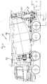
- FIG. 1 is a side view of a truck mixer 20 can be seen, the with the invention Swivel devices for a conveyor belt is provided, which in of the transport position shown in FIG. 1 folded onto the truck mixer 20 is.
- the conveyor belt not shown, runs over three articulated interconnected Frame parts 21, 22, 23, which can be designed to be telescopic to be able to adapt the delivery lengths to the local conditions.
- the inner frame part of the conveyor belt provided with a hopper 24 is pivotable about a horizontal axis 25 on the existing from a bearing block Support part 26 mounted, which in turn is fixed with a disc-shaped support structure 27 is connected.
- the support structure 27 is by clamping screws 28 screwed to a slewing ring 29, the balls held in ring grooves 30 is rotatably mounted on an inner ring 31, which also has clamping screws 32 the outer end portion of a swing arm 33 is connected.
- a rotary actuator for the turntable 29 is a worm 35 provided with a drive motor 34 provided with the outer worm teeth 36 of the slewing ring 29 in Intervention is.
- the worm drive 34 to 36 the slewing ring 29 can be twist the structures described about the vertical axis 37.
- the swivel arm 33 is screwed to a turntable 39 by means of clamping screws 38, of the balls held in ring grooves on an inner ring 40 is mounted, which is connected to a support structure 42 via clamping screws 41 which in turn is screwed to the vehicle frame 43 and one to it Console 44 is connected.
- the slewing ring 39 is in on its outer circumference provided with a worm toothing in the same way as the slewing ring 39, in which attacks a worm 35 which can be driven by a motor 34.
- the swivel arm 33 can be about its pivot axis 49 by about 180 ° and the inner frame part 21 of the conveyor belt pivot relative to the swivel arm 33 by an angle of approximately 280 °.
- the swivel arm 33 is either in the Fig. 4 apparent transport position I or II pivoted in which it is approximately parallel to the console 44 runs. In the transport position, the swivel arm 33 can on this fastened tabs 49 are locked with the console 44. Farther limit switches can be provided, which reach the swivel arm 33 stop the transport position.
Landscapes
- Engineering & Computer Science (AREA)
- Mechanical Engineering (AREA)
- Transportation (AREA)
- Health & Medical Sciences (AREA)
- Public Health (AREA)
- Structural Engineering (AREA)
- Preparation Of Clay, And Manufacture Of Mixtures Containing Clay Or Cement (AREA)
- Structure Of Belt Conveyors (AREA)
- Non-Deflectable Wheels, Steering Of Trailers, Or Other Steering (AREA)
- Framework For Endless Conveyors (AREA)
- Transmission Devices (AREA)
- Toys (AREA)
- Accessories For Mixers (AREA)
Abstract
Description
- Fig. 1
- eine Seitenansicht eines Fahrmischers, dessen um vertikale Achsen verschwenkbares Förderband mit der erfindungsgemäßen, aus Drehkränzen bestehenden Schwenkeinrichtung versehen ist,
- Fig. 2
- das Heck des Fahrmischers nach Fig. 1 in vergrößerter Darstellung,
- Fig. 3
- eine vergrößerte Darstellung der in Fig. 2 eingekreisten Verschwenkeinrichtung,
- Fig. 3a
- den in Fig. 3 eingekreisten Teil in vergrößerter Darstellung,
- Fig. 4
- eine Draufsicht auf die Schwenkeinrichtung nach den Fig. 1 bis 3 und
- Fig. 5 und 6
- die bereits beschriebene Verschwenkeinrichtung für ein Förderband eines bekannten Fahrmischers.
Claims (2)
- Fahrzeug, vorzugsweise Fahrmischer (20), mit einem an dem Fahrzeugrahmen (43) angebauten schwenkbaren Förderband (21 bis 23), dessen Tragteil (26) um eine vertikale Achse (37) drehbar an einem Schwenkarm (33) gelagert ist, der seinerseits um eine vertikale Achse (49) schwenkbar an dem Fahrzeugrahmen (43) oder einer mit diesem verbundenen Konsole (44) gelagert ist, und mit das Tragteil (26) und den Schwenkarm (33) verschwenkbaren Antrieben,
dadurch gekennzeichnet, daß der Schwenkarm (33) und das Tragteil (26) an mit Verzahnungen (36) versehenen Drehkränzen (39, 29) befestigt sind, deren diese lagernden ringförmigen Lagerkörper (40, 31) an dem Fahrzeugrahmen (43) bzw. der Konsole (44) und dem Schwenkarm (33) befestigt sind, und
daß die Antriebe aus angetriebenen Ritzeln oder angetriebenen Schnecken (35) bestehen, die mit den Verzahnungen (36) der Drehkränze (39, 29) im Eingriff sind. - Fahrzeug nach Anspruch 1, dadurch gekennzeichnet, daß die Drehkränze Kugeldrehkränze (39, 29) sind.
Applications Claiming Priority (2)
| Application Number | Priority Date | Filing Date | Title |
|---|---|---|---|
| DE20021668U DE20021668U1 (de) | 2000-12-21 | 2000-12-21 | Fahrzeug, vorzugsweise Fahrmischer, mit einem an den Fahrzeugrahmen angebauten schwenkbaren Förderband |
| DE20021668U | 2000-12-21 |
Publications (3)
| Publication Number | Publication Date |
|---|---|
| EP1216804A2 true EP1216804A2 (de) | 2002-06-26 |
| EP1216804A3 EP1216804A3 (de) | 2003-09-03 |
| EP1216804B1 EP1216804B1 (de) | 2006-03-22 |
Family
ID=7950399
Family Applications (1)
| Application Number | Title | Priority Date | Filing Date |
|---|---|---|---|
| EP01130109A Expired - Lifetime EP1216804B1 (de) | 2000-12-21 | 2001-12-18 | Fahrzeug, vorzugsweise Fahrmischer, mit einem an den Fahrzeugrahmen angebauten schwenkbaren Förderband |
Country Status (5)
| Country | Link |
|---|---|
| EP (1) | EP1216804B1 (de) |
| AT (1) | ATE320898T1 (de) |
| DE (2) | DE20021668U1 (de) |
| DK (1) | DK1216804T3 (de) |
| ES (1) | ES2258056T3 (de) |
Cited By (5)
| Publication number | Priority date | Publication date | Assignee | Title |
|---|---|---|---|---|
| FR2868055A1 (fr) * | 2004-03-29 | 2005-09-30 | Theam Sa | Mecanisme pour bras de support de convoyeur et ensemble de bras de support equipe d'un tel mecanisme |
| FR2870182A1 (fr) * | 2004-05-13 | 2005-11-18 | Belt Sarl | Vehicule de transport du beton equipe d'un convoyeur de transport |
| FR2870181A1 (fr) * | 2004-05-13 | 2005-11-18 | Belt Sarl | Tourelle pour un convoyeur notamment a bande destine a etre monte sur un vehicule |
| CN102501794A (zh) * | 2011-10-18 | 2012-06-20 | 三一重工股份有限公司 | 一种混凝土搅拌运输车 |
| CN102529784A (zh) * | 2012-02-24 | 2012-07-04 | 三一重工股份有限公司 | 一种自动卸料系统及混凝土搅拌车 |
Families Citing this family (4)
| Publication number | Priority date | Publication date | Assignee | Title |
|---|---|---|---|---|
| DE10342235A1 (de) * | 2003-09-11 | 2005-04-07 | Glama Maschinenbau Gmbh | Silofahrzeug, insbesondere Beschickungsfahrzeug |
| US7891479B2 (en) | 2007-09-07 | 2011-02-22 | Carl Evangelista | Modular conveyor system |
| DE102009026290A1 (de) * | 2009-07-30 | 2011-02-03 | Amazonen-Werke H. Dreyer Gmbh & Co. Kg | Landwirtschaftliche Verteilmaschine |
| CN105619614B (zh) * | 2016-03-21 | 2017-10-27 | 杭州江河机电装备工程有限公司 | 大容量高支点自落式混凝土搅拌机 |
Citations (3)
| Publication number | Priority date | Publication date | Assignee | Title |
|---|---|---|---|---|
| DE2234627A1 (de) * | 1971-12-16 | 1973-06-20 | Symons Corp | Fahrzeug zum transport von fliessfaehigem material, insbesondere von auf dem fahrzeug gemischtem beton |
| US3828949A (en) * | 1973-05-23 | 1974-08-13 | Symons Corp | Power-actuated distributing conveyor system for a ready-mix concrete truck |
| US5551776A (en) * | 1995-03-30 | 1996-09-03 | Zimmerman; Harold M. | Telescoping discharge chute for concrete trucks |
-
2000
- 2000-12-21 DE DE20021668U patent/DE20021668U1/de not_active Expired - Lifetime
-
2001
- 2001-12-18 EP EP01130109A patent/EP1216804B1/de not_active Expired - Lifetime
- 2001-12-18 AT AT01130109T patent/ATE320898T1/de active
- 2001-12-18 ES ES01130109T patent/ES2258056T3/es not_active Expired - Lifetime
- 2001-12-18 DE DE50109280T patent/DE50109280D1/de not_active Expired - Lifetime
- 2001-12-18 DK DK01130109T patent/DK1216804T3/da active
Patent Citations (3)
| Publication number | Priority date | Publication date | Assignee | Title |
|---|---|---|---|---|
| DE2234627A1 (de) * | 1971-12-16 | 1973-06-20 | Symons Corp | Fahrzeug zum transport von fliessfaehigem material, insbesondere von auf dem fahrzeug gemischtem beton |
| US3828949A (en) * | 1973-05-23 | 1974-08-13 | Symons Corp | Power-actuated distributing conveyor system for a ready-mix concrete truck |
| US5551776A (en) * | 1995-03-30 | 1996-09-03 | Zimmerman; Harold M. | Telescoping discharge chute for concrete trucks |
Cited By (7)
| Publication number | Priority date | Publication date | Assignee | Title |
|---|---|---|---|---|
| FR2868055A1 (fr) * | 2004-03-29 | 2005-09-30 | Theam Sa | Mecanisme pour bras de support de convoyeur et ensemble de bras de support equipe d'un tel mecanisme |
| EP1582326A1 (de) * | 2004-03-29 | 2005-10-05 | Theam | Mechanismus für einen Fördertragarm und Tragarmvorrichtung mit solchem Mechanismus |
| FR2870182A1 (fr) * | 2004-05-13 | 2005-11-18 | Belt Sarl | Vehicule de transport du beton equipe d'un convoyeur de transport |
| FR2870181A1 (fr) * | 2004-05-13 | 2005-11-18 | Belt Sarl | Tourelle pour un convoyeur notamment a bande destine a etre monte sur un vehicule |
| CN102501794A (zh) * | 2011-10-18 | 2012-06-20 | 三一重工股份有限公司 | 一种混凝土搅拌运输车 |
| CN102501794B (zh) * | 2011-10-18 | 2015-11-04 | 三一汽车制造有限公司 | 一种混凝土搅拌运输车 |
| CN102529784A (zh) * | 2012-02-24 | 2012-07-04 | 三一重工股份有限公司 | 一种自动卸料系统及混凝土搅拌车 |
Also Published As
| Publication number | Publication date |
|---|---|
| EP1216804A3 (de) | 2003-09-03 |
| ES2258056T3 (es) | 2006-08-16 |
| ATE320898T1 (de) | 2006-04-15 |
| DK1216804T3 (da) | 2006-05-01 |
| DE20021668U1 (de) | 2001-03-08 |
| EP1216804B1 (de) | 2006-03-22 |
| DE50109280D1 (de) | 2006-05-11 |
Similar Documents
| Publication | Publication Date | Title |
|---|---|---|
| EP1216804B1 (de) | Fahrzeug, vorzugsweise Fahrmischer, mit einem an den Fahrzeugrahmen angebauten schwenkbaren Förderband | |
| DE10084078B3 (de) | Rahmenstruktur für einen Bandförderer | |
| DE2227446C3 (de) | Doppelkran | |
| DE19524195C1 (de) | Einstellvorrichtung zur Neigungsverstellung eines schwenkbar angelenkten Mantelrohres einer Lenkspindel eines Kraftfahrzeuges | |
| DE2742498A1 (de) | Vorrichtung zum aufnehmen und foerdern von schuettgut | |
| DE2950354C2 (de) | Motorisch verstellbarer, insbesondere in einem Fahrzeug, vorzugsweise Kraftwagen, anzuordnender Sitz | |
| DE2643653C2 (de) | Vorrichtung an mindestens zwei im Winkel zueinander angeordneten Förderern | |
| DE2902767A1 (de) | Hebezeug, insbesondere nach art eines krans | |
| DE2008706A1 (de) | Spannvorrichtung für ein Zugmittel | |
| DE2308558C3 (de) | Vorrichtung zum kontinuierlichen Löschen von trockenem Massengut, insbesondere aus Schiffen | |
| DE2037380B2 (de) | Verteilförderanlage mit kippbaren Plattformen | |
| DE102005009252B4 (de) | Hydraulische Schwenkvorrichtung | |
| DE19521833A1 (de) | Handhabungsgerät für zu demontierende Alt-Kraftfahrzeuge | |
| EP0832831B1 (de) | Vorrichtung zum kontinuierlichen Be- und Entladen, insbesondere von Schiffen, mit Stückgut | |
| DE1914393A1 (de) | Tomograph | |
| DE718656C (de) | Kippsicherung fuer Kraftfahrdrehleitern, Maste, Traeger o. dgl. | |
| DE4344675C2 (de) | Schaukelantriebsvorrichtung für Sitz- oder Liegegegenstände, insbesondere für tragbare Baby-Sitze | |
| DE3805971C2 (de) | ||
| DE1907084C3 (de) | ||
| DE2366613C2 (de) | Doppelkran | |
| DE4129807A1 (de) | Anordnung und lagerung des antriebs des schwenkarmes eines saeulen-schwenkkranes | |
| DE404686C (de) | Knickbarer Zubringer fuer Torfmaschinen u. dgl. | |
| DE2130653A1 (de) | Zwei-Saeulen-UEberflur-Hebebuehne | |
| DE3218694C2 (de) | Tragrohr eines Steilförderers, insbesondere Senkrechtförderers, bzw. einer Niedertragvorrichtung | |
| DE1927659C (de) | Vorrichtung zur Entleerung eines Silos |
Legal Events
| Date | Code | Title | Description |
|---|---|---|---|
| PUAI | Public reference made under article 153(3) epc to a published international application that has entered the european phase |
Free format text: ORIGINAL CODE: 0009012 |
|
| AK | Designated contracting states |
Kind code of ref document: A2 Designated state(s): AT BE CH CY DE DK ES FI FR GB GR IE IT LI LU MC NL PT SE TR |
|
| AX | Request for extension of the european patent |
Free format text: AL;LT;LV;MK;RO;SI |
|
| PUAL | Search report despatched |
Free format text: ORIGINAL CODE: 0009013 |
|
| AK | Designated contracting states |
Kind code of ref document: A3 Designated state(s): AT BE CH CY DE DK ES FI FR GB GR IE IT LI LU MC NL PT SE TR |
|
| AX | Request for extension of the european patent |
Extension state: AL LT LV MK RO SI |
|
| 17P | Request for examination filed |
Effective date: 20040204 |
|
| 17Q | First examination report despatched |
Effective date: 20040413 |
|
| AKX | Designation fees paid |
Designated state(s): AT BE CH CY DE DK ES FI FR GB GR IE IT LI LU MC NL PT SE TR |
|
| GRAP | Despatch of communication of intention to grant a patent |
Free format text: ORIGINAL CODE: EPIDOSNIGR1 |
|
| GRAS | Grant fee paid |
Free format text: ORIGINAL CODE: EPIDOSNIGR3 |
|
| GRAA | (expected) grant |
Free format text: ORIGINAL CODE: 0009210 |
|
| AK | Designated contracting states |
Kind code of ref document: B1 Designated state(s): AT BE CH CY DE DK ES FI FR GB GR IE IT LI LU MC NL PT SE TR |
|
| PG25 | Lapsed in a contracting state [announced via postgrant information from national office to epo] |
Ref country code: NL Free format text: LAPSE BECAUSE OF FAILURE TO SUBMIT A TRANSLATION OF THE DESCRIPTION OR TO PAY THE FEE WITHIN THE PRESCRIBED TIME-LIMIT Effective date: 20060322 |
|
| REG | Reference to a national code |
Ref country code: GB Ref legal event code: FG4D Free format text: NOT ENGLISH |
|
| REG | Reference to a national code |
Ref country code: CH Ref legal event code: EP |
|
| REG | Reference to a national code |
Ref country code: CH Ref legal event code: NV Representative=s name: BOVARD AG PATENTANWAELTE |
|
| REG | Reference to a national code |
Ref country code: IE Ref legal event code: FG4D Free format text: LANGUAGE OF EP DOCUMENT: GERMAN |
|
| REG | Reference to a national code |
Ref country code: DK Ref legal event code: T3 |
|
| REF | Corresponds to: |
Ref document number: 50109280 Country of ref document: DE Date of ref document: 20060511 Kind code of ref document: P |
|
| PG25 | Lapsed in a contracting state [announced via postgrant information from national office to epo] |
Ref country code: SE Free format text: LAPSE BECAUSE OF FAILURE TO SUBMIT A TRANSLATION OF THE DESCRIPTION OR TO PAY THE FEE WITHIN THE PRESCRIBED TIME-LIMIT Effective date: 20060622 |
|
| GBT | Gb: translation of ep patent filed (gb section 77(6)(a)/1977) |
Effective date: 20060607 |
|
| REG | Reference to a national code |
Ref country code: ES Ref legal event code: FG2A Ref document number: 2258056 Country of ref document: ES Kind code of ref document: T3 |
|
| PG25 | Lapsed in a contracting state [announced via postgrant information from national office to epo] |
Ref country code: PT Free format text: LAPSE BECAUSE OF FAILURE TO SUBMIT A TRANSLATION OF THE DESCRIPTION OR TO PAY THE FEE WITHIN THE PRESCRIBED TIME-LIMIT Effective date: 20060822 |
|
| NLV1 | Nl: lapsed or annulled due to failure to fulfill the requirements of art. 29p and 29m of the patents act | ||
| ET | Fr: translation filed | ||
| PG25 | Lapsed in a contracting state [announced via postgrant information from national office to epo] |
Ref country code: BE Free format text: LAPSE BECAUSE OF NON-PAYMENT OF DUE FEES Effective date: 20061231 Ref country code: MC Free format text: LAPSE BECAUSE OF NON-PAYMENT OF DUE FEES Effective date: 20061231 |
|
| PLBE | No opposition filed within time limit |
Free format text: ORIGINAL CODE: 0009261 |
|
| STAA | Information on the status of an ep patent application or granted ep patent |
Free format text: STATUS: NO OPPOSITION FILED WITHIN TIME LIMIT |
|
| 26N | No opposition filed |
Effective date: 20061227 |
|
| BERE | Be: lapsed |
Owner name: LIEBHERR-MISCHTECHNIK G.M.B.H. Effective date: 20061231 |
|
| PG25 | Lapsed in a contracting state [announced via postgrant information from national office to epo] |
Ref country code: GR Free format text: LAPSE BECAUSE OF FAILURE TO SUBMIT A TRANSLATION OF THE DESCRIPTION OR TO PAY THE FEE WITHIN THE PRESCRIBED TIME-LIMIT Effective date: 20060623 |
|
| PG25 | Lapsed in a contracting state [announced via postgrant information from national office to epo] |
Ref country code: FI Free format text: LAPSE BECAUSE OF FAILURE TO SUBMIT A TRANSLATION OF THE DESCRIPTION OR TO PAY THE FEE WITHIN THE PRESCRIBED TIME-LIMIT Effective date: 20060322 |
|
| PG25 | Lapsed in a contracting state [announced via postgrant information from national office to epo] |
Ref country code: TR Free format text: LAPSE BECAUSE OF FAILURE TO SUBMIT A TRANSLATION OF THE DESCRIPTION OR TO PAY THE FEE WITHIN THE PRESCRIBED TIME-LIMIT Effective date: 20060322 Ref country code: LU Free format text: LAPSE BECAUSE OF NON-PAYMENT OF DUE FEES Effective date: 20061218 |
|
| PG25 | Lapsed in a contracting state [announced via postgrant information from national office to epo] |
Ref country code: CY Free format text: LAPSE BECAUSE OF FAILURE TO SUBMIT A TRANSLATION OF THE DESCRIPTION OR TO PAY THE FEE WITHIN THE PRESCRIBED TIME-LIMIT Effective date: 20060322 |
|
| REG | Reference to a national code |
Ref country code: CH Ref legal event code: PFA Owner name: LIEBHERR-MISCHTECHNIK GMBH Free format text: LIEBHERR-MISCHTECHNIK GMBH#IM ELCHGRUND 12#88427 BAD SCHUSSENRIED (DE) -TRANSFER TO- LIEBHERR-MISCHTECHNIK GMBH#IM ELCHGRUND 12#88427 BAD SCHUSSENRIED (DE) |
|
| REG | Reference to a national code |
Ref country code: FR Ref legal event code: PLFP Year of fee payment: 15 |
|
| REG | Reference to a national code |
Ref country code: FR Ref legal event code: PLFP Year of fee payment: 16 |
|
| REG | Reference to a national code |
Ref country code: FR Ref legal event code: PLFP Year of fee payment: 17 |
|
| PGFP | Annual fee paid to national office [announced via postgrant information from national office to epo] |
Ref country code: IE Payment date: 20191220 Year of fee payment: 19 |
|
| PGFP | Annual fee paid to national office [announced via postgrant information from national office to epo] |
Ref country code: GB Payment date: 20191220 Year of fee payment: 19 |
|
| PGFP | Annual fee paid to national office [announced via postgrant information from national office to epo] |
Ref country code: CH Payment date: 20201227 Year of fee payment: 20 Ref country code: FR Payment date: 20201228 Year of fee payment: 20 Ref country code: AT Payment date: 20201221 Year of fee payment: 20 Ref country code: DK Payment date: 20201227 Year of fee payment: 20 |
|
| PGFP | Annual fee paid to national office [announced via postgrant information from national office to epo] |
Ref country code: ES Payment date: 20210108 Year of fee payment: 20 Ref country code: DE Payment date: 20201224 Year of fee payment: 20 |
|
| GBPC | Gb: european patent ceased through non-payment of renewal fee |
Effective date: 20201218 |
|
| PG25 | Lapsed in a contracting state [announced via postgrant information from national office to epo] |
Ref country code: IE Free format text: LAPSE BECAUSE OF NON-PAYMENT OF DUE FEES Effective date: 20201218 |
|
| PGFP | Annual fee paid to national office [announced via postgrant information from national office to epo] |
Ref country code: IT Payment date: 20201231 Year of fee payment: 20 |
|
| PG25 | Lapsed in a contracting state [announced via postgrant information from national office to epo] |
Ref country code: GB Free format text: LAPSE BECAUSE OF NON-PAYMENT OF DUE FEES Effective date: 20201218 |
|
| REG | Reference to a national code |
Ref country code: DE Ref legal event code: R071 Ref document number: 50109280 Country of ref document: DE |
|
| REG | Reference to a national code |
Ref country code: DK Ref legal event code: EUP Expiry date: 20211218 |
|
| REG | Reference to a national code |
Ref country code: CH Ref legal event code: PL |
|
| REG | Reference to a national code |
Ref country code: AT Ref legal event code: MK07 Ref document number: 320898 Country of ref document: AT Kind code of ref document: T Effective date: 20211218 |
|
| REG | Reference to a national code |
Ref country code: ES Ref legal event code: FD2A Effective date: 20220405 |
|
| PG25 | Lapsed in a contracting state [announced via postgrant information from national office to epo] |
Ref country code: ES Free format text: LAPSE BECAUSE OF EXPIRATION OF PROTECTION Effective date: 20211219 |