EP1213207B2 - Tragstruktur für Kraftfahrzeugkühlerblock - Google Patents
Tragstruktur für Kraftfahrzeugkühlerblock Download PDFInfo
- Publication number
- EP1213207B2 EP1213207B2 EP01129015.2A EP01129015A EP1213207B2 EP 1213207 B2 EP1213207 B2 EP 1213207B2 EP 01129015 A EP01129015 A EP 01129015A EP 1213207 B2 EP1213207 B2 EP 1213207B2
- Authority
- EP
- European Patent Office
- Prior art keywords
- core support
- radiator core
- section
- support structure
- upper section
- Prior art date
- Legal status (The legal status is an assumption and is not a legal conclusion. Google has not performed a legal analysis and makes no representation as to the accuracy of the status listed.)
- Expired - Lifetime
Links
- 230000002787 reinforcement Effects 0.000 claims description 37
- 229920003002 synthetic resin Polymers 0.000 claims description 34
- 239000000057 synthetic resin Substances 0.000 claims description 34
- 239000002184 metal Substances 0.000 claims description 24
- 238000009434 installation Methods 0.000 claims description 21
- 230000004323 axial length Effects 0.000 claims description 2
- 229920005989 resin Polymers 0.000 description 13
- 239000011347 resin Substances 0.000 description 13
- 238000001746 injection moulding Methods 0.000 description 5
- 230000008878 coupling Effects 0.000 description 4
- 238000010168 coupling process Methods 0.000 description 4
- 238000005859 coupling reaction Methods 0.000 description 4
- 238000000034 method Methods 0.000 description 4
- 230000008569 process Effects 0.000 description 4
- 238000000605 extraction Methods 0.000 description 3
- 230000009471 action Effects 0.000 description 2
- 239000010729 system oil Substances 0.000 description 2
- 230000008859 change Effects 0.000 description 1
- 230000001419 dependent effect Effects 0.000 description 1
- 239000012467 final product Substances 0.000 description 1
- 238000012423 maintenance Methods 0.000 description 1
- 230000007246 mechanism Effects 0.000 description 1
- 239000003921 oil Substances 0.000 description 1
- 239000000047 product Substances 0.000 description 1
- 239000002994 raw material Substances 0.000 description 1
- 238000003466 welding Methods 0.000 description 1
Images






Classifications
-
- B—PERFORMING OPERATIONS; TRANSPORTING
- B62—LAND VEHICLES FOR TRAVELLING OTHERWISE THAN ON RAILS
- B62D—MOTOR VEHICLES; TRAILERS
- B62D29/00—Superstructures, understructures, or sub-units thereof, characterised by the material thereof
- B62D29/001—Superstructures, understructures, or sub-units thereof, characterised by the material thereof characterised by combining metal and synthetic material
-
- B—PERFORMING OPERATIONS; TRANSPORTING
- B29—WORKING OF PLASTICS; WORKING OF SUBSTANCES IN A PLASTIC STATE IN GENERAL
- B29C—SHAPING OR JOINING OF PLASTICS; SHAPING OF MATERIAL IN A PLASTIC STATE, NOT OTHERWISE PROVIDED FOR; AFTER-TREATMENT OF THE SHAPED PRODUCTS, e.g. REPAIRING
- B29C45/00—Injection moulding, i.e. forcing the required volume of moulding material through a nozzle into a closed mould; Apparatus therefor
- B29C45/14—Injection moulding, i.e. forcing the required volume of moulding material through a nozzle into a closed mould; Apparatus therefor incorporating preformed parts or layers, e.g. injection moulding around inserts or for coating articles
- B29C45/14065—Positioning or centering articles in the mould
-
- B—PERFORMING OPERATIONS; TRANSPORTING
- B62—LAND VEHICLES FOR TRAVELLING OTHERWISE THAN ON RAILS
- B62D—MOTOR VEHICLES; TRAILERS
- B62D25/00—Superstructure or monocoque structure sub-units; Parts or details thereof not otherwise provided for
- B62D25/08—Front or rear portions
- B62D25/082—Engine compartments
- B62D25/084—Radiator supports
-
- B—PERFORMING OPERATIONS; TRANSPORTING
- B62—LAND VEHICLES FOR TRAVELLING OTHERWISE THAN ON RAILS
- B62D—MOTOR VEHICLES; TRAILERS
- B62D29/00—Superstructures, understructures, or sub-units thereof, characterised by the material thereof
- B62D29/001—Superstructures, understructures, or sub-units thereof, characterised by the material thereof characterised by combining metal and synthetic material
- B62D29/004—Superstructures, understructures, or sub-units thereof, characterised by the material thereof characterised by combining metal and synthetic material the metal being over-moulded by the synthetic material, e.g. in a mould
-
- B—PERFORMING OPERATIONS; TRANSPORTING
- B29—WORKING OF PLASTICS; WORKING OF SUBSTANCES IN A PLASTIC STATE IN GENERAL
- B29C—SHAPING OR JOINING OF PLASTICS; SHAPING OF MATERIAL IN A PLASTIC STATE, NOT OTHERWISE PROVIDED FOR; AFTER-TREATMENT OF THE SHAPED PRODUCTS, e.g. REPAIRING
- B29C45/00—Injection moulding, i.e. forcing the required volume of moulding material through a nozzle into a closed mould; Apparatus therefor
- B29C2045/0093—Injection moulding, i.e. forcing the required volume of moulding material through a nozzle into a closed mould; Apparatus therefor of articles provided with an attaching element
-
- B—PERFORMING OPERATIONS; TRANSPORTING
- B29—WORKING OF PLASTICS; WORKING OF SUBSTANCES IN A PLASTIC STATE IN GENERAL
- B29C—SHAPING OR JOINING OF PLASTICS; SHAPING OF MATERIAL IN A PLASTIC STATE, NOT OTHERWISE PROVIDED FOR; AFTER-TREATMENT OF THE SHAPED PRODUCTS, e.g. REPAIRING
- B29C45/00—Injection moulding, i.e. forcing the required volume of moulding material through a nozzle into a closed mould; Apparatus therefor
- B29C45/17—Component parts, details or accessories; Auxiliary operations
- B29C45/26—Moulds
- B29C45/33—Moulds having transversely, e.g. radially, movable mould parts
- B29C2045/338—Mould parts with combined axial and transversal movements
-
- B—PERFORMING OPERATIONS; TRANSPORTING
- B29—WORKING OF PLASTICS; WORKING OF SUBSTANCES IN A PLASTIC STATE IN GENERAL
- B29C—SHAPING OR JOINING OF PLASTICS; SHAPING OF MATERIAL IN A PLASTIC STATE, NOT OTHERWISE PROVIDED FOR; AFTER-TREATMENT OF THE SHAPED PRODUCTS, e.g. REPAIRING
- B29C45/00—Injection moulding, i.e. forcing the required volume of moulding material through a nozzle into a closed mould; Apparatus therefor
- B29C45/14—Injection moulding, i.e. forcing the required volume of moulding material through a nozzle into a closed mould; Apparatus therefor incorporating preformed parts or layers, e.g. injection moulding around inserts or for coating articles
- B29C45/14311—Injection moulding, i.e. forcing the required volume of moulding material through a nozzle into a closed mould; Apparatus therefor incorporating preformed parts or layers, e.g. injection moulding around inserts or for coating articles using means for bonding the coating to the articles
-
- B—PERFORMING OPERATIONS; TRANSPORTING
- B29—WORKING OF PLASTICS; WORKING OF SUBSTANCES IN A PLASTIC STATE IN GENERAL
- B29C—SHAPING OR JOINING OF PLASTICS; SHAPING OF MATERIAL IN A PLASTIC STATE, NOT OTHERWISE PROVIDED FOR; AFTER-TREATMENT OF THE SHAPED PRODUCTS, e.g. REPAIRING
- B29C45/00—Injection moulding, i.e. forcing the required volume of moulding material through a nozzle into a closed mould; Apparatus therefor
- B29C45/14—Injection moulding, i.e. forcing the required volume of moulding material through a nozzle into a closed mould; Apparatus therefor incorporating preformed parts or layers, e.g. injection moulding around inserts or for coating articles
- B29C45/14836—Preventing damage of inserts during injection, e.g. collapse of hollow inserts, breakage
-
- B—PERFORMING OPERATIONS; TRANSPORTING
- B29—WORKING OF PLASTICS; WORKING OF SUBSTANCES IN A PLASTIC STATE IN GENERAL
- B29L—INDEXING SCHEME ASSOCIATED WITH SUBCLASS B29C, RELATING TO PARTICULAR ARTICLES
- B29L2031/00—Other particular articles
- B29L2031/30—Vehicles, e.g. ships or aircraft, or body parts thereof
- B29L2031/3002—Superstructures characterized by combining metal and plastics, i.e. hybrid parts
-
- B—PERFORMING OPERATIONS; TRANSPORTING
- B29—WORKING OF PLASTICS; WORKING OF SUBSTANCES IN A PLASTIC STATE IN GENERAL
- B29L—INDEXING SCHEME ASSOCIATED WITH SUBCLASS B29C, RELATING TO PARTICULAR ARTICLES
- B29L2031/00—Other particular articles
- B29L2031/30—Vehicles, e.g. ships or aircraft, or body parts thereof
- B29L2031/3005—Body finishings
Definitions
- This invention relates to a radiator core support structure for a vehicle.
- radiator core support structure for an automotive vehicle has taken such a basic configuration that radiator core support upper and lower sections are provided to extend generally along the direction of width of the vehicle, and the laterally central parts of the radiator core support upper and lower sections are connected by a hood lock stay which generally vertically extends.
- all the basic component parts are formed of metal, and therefore a torsional deformation and a dimensional error tend to readily occur in an assembly process in which the basic component parts are assembled under welding so that an installation operation of the radiator core support structure to a vehicle body becomes difficult after the assembly process.
- the radiator core support structure is formed of synthetic resin thereby providing a so-called hybrid structure which is free from causes for producing the torsional deformation and the assembly dimensional error.
- the radiator core support upper section and/or the like are formed to have a so-called open loop-shaped cross-section to form a channel, and a resin-reinforcement section (such as resin-reinforcement ribs) as disclosed in Japanese Patent No. 2931605 corresponding to EP-A-0 370 342 is integrally formed inside and along the channel of the radiator core support upper section and/or the like.
- the reinforcement section is formed only at one side (inside of the channel) of the radiator core support upper section and/or the like, and therefore there is a fear that the united condition between the reinforcement section and the radiator core support upper section and/or the like will be broken when a large load is applied to the reinforcement section in a direction in which the reinforcement section separates from the radiator core support upper section and/or the like.
- radiator core support structure for a vehicle, wherein the radiator core support structure is high in structural rigidity.
- the whole body and essential parts of the radiator core support structure are high in structural rigidity as compared with the conventional radiator core support structures.
- the reinforcement section of the radiator core support structure formed of synthetic resin can be effectively prevented from being peeled off from a radiator core support upper section and/or the like.
- the radiator core support structure has a radiator core support upper section and/or the like which is formed with a channel whose inside is filled with a plurality of reinforcement ribs formed of synthetic resin, in which the reinforcement ribs can be effectively prevented from being broken during extraction of the reinforcement ribs form a metallic mold.
- the radiator core supporting structure 1 is assembled with a bumper 3, bumper stays 4, head lights 5, an oil cooler tube 6 of a power steering system, a condenser 7, a radiator 8, a fan shroud 9 and the like to form a module.
- the radiator core supporting structure 1 is installed in the form of the module and not in the form of the single radiator core supporting structure, to a front structure 2 of a vehicle body of an automotive vehicle as shown in Fig. 1 .
- the vehicle body front structure 2 includes a pair of front side members 10 which are located opposite sides of an engine compartment E and extends in the fore and aft directions.
- Each front side member 10 has a closed loop-shaped cross-section or generally O-shaped cross-section.
- a hood-ledge panel 11 is formed outside and above the front side member 10.
- a hood-ledge reinforcement 12 is joined to and located outside the hood-ledge panel 11, thereby to form a structure having a closed loop-shaped cross-section.
- the radiator core supporting structure 1 includes a radiator core support upper section 13 and a radiator core support lowers section 14 which are located respectively at the upper side and the lower side to be vertically separate from each other.
- Each of the radiator core support upper and lower sections 13, 14 extends laterally or in the direction of width of the vehicle.
- a hood lock stay 15 is provided to generally vertically extend and connect laterally central parts of the radiator core support upper and lower sections 13, 14. In other words, an upper end section of the hood lock stay 15 is fixedly connected to the central part of the radiator core support upper section 13 while a lower end section of the hood lock stay 15 is fixedly connected to the central part of the radiator core support lower section 14.
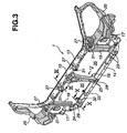
- the radiator core support structure 1 includes parts (indicated as bright sections) formed of metal and parts (indicated as being dark sections) formed of synthetic resin or plastic, as shown in Fig. 3 .
- the parts formed of metal are shown in Fig. 4 . More specifically, the radiator core support upper section 13, a hood lock installation section 16 to be welded to the central part of the radiator core support upper section 13, the radiator core support lower section 14, and side sections 17 to be welded respectively to the opposite end sections of the radiator core support lower section 14 are formed of metal.
- the other sections in the radiator core support structure 1 shown in Fig. 3 are formed of synthetic resin.
- hood lock installation section 16 has been shown and described as being in a state where the section 16 formed as a separate member is installed to the radiator core upper section 13, it will be understood that the section 16 may be formed integral with the radiator core support upper section 13. Similarly, the side sections 17 may be formed integral with the radiator core support lower section 14.
- Each of the radiator core support upper section 13 and the radiator core support lower sections 14 has a generally C-shaped cross-section or open loop-shaped cross-section as shown in Figs. 5 and 6 .
- the radiator core support structure 1 is produced by setting the radiator core support upper and lower sections 13, 14 in a cavity of a metallic mold 18 in their state where the food lock installation section 16 and the side sections 17 are installed to them, and then by injecting synthetic resin into the cavity, thus accomplishing an injection molding.
- the injected synthetic resin mainly forms the hood lock stay 15, pillar sections 19 for connecting the radiator core support upper section 13 and the radiator core support lower section 14 in a condition where the inboard side edge portion of each side section 17 is embedded in the pillar section 19, and lamp installation sections 20 each of which connects the side section 17 and one of the opposite end sections of the radiator core support upper section 13.
- two openings 35 for the radiator are formed in the thus produced radiator core support structure 1, in which one opening 35 is located between the left-side pillar section 19 and the hood lock stay 15 while the other opening 35 is located between the right-side pillar section 19 and the hood lock stay 15.
- the injected synthetic resin forms a plurality of inclined or reinforcement ribs (resin-reinforcement section) 21, 22 which are formed in the channel C of the generally channel-shaped radiator core support upper section 13 and in the channel C of the generally channel-shaped radiator core support lower section 14.
- the inclined ribs 21, 22 are formed extending along the length of the radiator core support upper section 13 and the radiator core support lower section 14. These inclined ribs 21, 22 extend from each of the upper and lower end sections of the hood lock stay 15 into each of the channels C of the radiator core support upper and lower sections 13, 14.
- Each of the inclined ribs 21, 22 is generally plate-shaped and extends from the inner surface of the upper wall W1 to the inner surface of the lower wall W2 as shown in Figs.
- Each of the inclined ribs 21, 22 extends generally perpendicular to the bottom wall W3 connecting the upper and lower walls W1, W2.
- the inclined ribs 21, 22 form a zigzag pattern rib structure which continuously extends in the direction of width of the vehicle in a zigzag pattern and reaches the opposite end sections of the radiator core support upper and lower sections 13, 14.
- Each of the inclined ribs 21, 22 is formed with a generally cylindrical or column-like struck portion 23 which is formed at the central part of the rib and extends generally parallel with the upper and lower walls W1, W2 as shown in Fig. 6 . This struck portion 23 is used during the injection molding using the metallic mold 18 and will be discussed after.
- each of the inclined ribs 21, 22 inclines to form an angle of 45° relative to an imaginary horizontal plane (vertical to the bottom wall W3) extending in the longitudinal direction of the radiator core support upper and lower sections 13, 14. This angle is very effective for improving the buckling strength and torsional rigidity of the radiator core support upper and upper sections 13, 14.
- the radiator core support upper section 13 located at the upper side and the radiator core support lower section 14 located at the lower side are connected to each other through the pillar sections 19, and therefore loads in vertical directions can be transmitted not only through the hood lock stay 15 and but also through the pillar sections 19. This can improve the rigidity of the radiator core support structure 1 in the vertical direction. Additionally, since each of the pillar sections 19 is rigidly connected to the inboard side edge portion of each of the side sections 17, the radiator core support structure 1 is put in a state where its upper, lower and lateral parts are connected by the pillar sections 19 thereby improving the torsional rigidity around the side sections 17.
- each of the lamp installation sections 20 having a complicated three-dimensional shape is located to fill the space between each of the opposite end sections of the radiator core support upper section 18 and each of the side sections 17, and therefore the whole body of the radiator core support structure 1 can be improved in torsional rigidity.
- the main body section of the hood lock stay 15 has a generally C-shaped cross-section or open loop-shaped cross-section which opens rearward.
- the bottom or front wall 15a of the lower end section of the hood lock stay 15 is inclined rearward and connected to the rear end section of the radiator core support lower section 14.
- the reason why the cross-sectional shape of the lower end section of the hood lock stay 15 is different from or changed relative to that of the upper end section is that the radiator core support lower section 14 has the generally C-shaped cross-section, and it is necessary to put the radiator core support lower section 14 between a stationary mold 86 and a movable mold 37 of the metallic mold 18 as discussed after.
- the lower end section of the hood lock stay 16 has forward extending flanges 25 located respectively at the right-side and left-side thereof in order to prevent a rigidity lowering due to change in cross-sectional shape.
- the forward extending flanges 25 are located at the right-side and left-side of the inclined bottom wall 15a and extends forward or in the direction in which the side walls 15b, 15c of the hood lock stay 15 extend.
- the hood lock installation section 16 formed of metal is welded to the laterally central part of the radiator core support upper section 13 corresponding to the upper end section of the hood lock stay 15, and therefore the rigidity of the food lock installation section 16 becomes high. Accordingly, a force for engaging a hood lock mechanism (not shown) attached to the hood lock installation section 16 to a striker (not shown) of an engine hood is raised thereby effectively preventing the engine hood from fluttering during a vehicle running.
- the hood lock installation section 16 is formed at its lower end part with a bent portion 26 which extends perpendicular and rearward from and the main body portion (not identified) of the hood lock installation section 16.
- the bent portion 26 is embedded in the upper end section of the hood lock stay 15 formed of synthetic resin. Accordingly, a downward load applied to the hood lock installation section 16 can be securely transmitted to the hood lock stay 15 when the engine hood is closed.
- the radiator core support upper section 13 and the radiator core support lower section 14 are provided in their channel C with the inclined ribs 21, 22. Additionally, four resin covering or wrapping sections 27 are formed on the radiator core support upper section 13, and five resin covering or wrapping sections 28, 29 are formed on the radiator core support lower section 14, as shown in Figs. 3 , 8 , 9 and 10 .
- Each resin covering section 27, 28, 29 is formed by allowing synthetic resin to flow from the back-side (the inside of the channel C) of the wall of the radiator support upper or lower section 13, 14 to the front-side of the wall, so that the resin covering section 27, 28, 29 is contiguous with the inclined ribs 21, 22 located inside the channel C of the radiator support upper or lower section 13, 14.
- the resin covering section 27, 28, 29 is formed band-shaped and surrounds the outer surface (the outer surfaces of the upper, lower and bottom walls W1, W2, W3) of the radiator support upper or lower section 13, 14.
- the parts formed of metal and the parts formed of synthetic resin can be securely united.
- the flange sections F extended from the upper and lower walls W1, W2, W3 of the radiator core support upper and lower sections 13, 14 are formed respectively with through-holes (not identified) through which synthetic resin flows.
- the flange sections F may be formed at their end edge portions with a semicircular cutout (not shown) or the like; or the end edge portion of the flange sections F may be bent to have an angle relative to the surface of the main body of the flange section F.
- the above-mentioned resin covering sections 27, 28, 29 are formed to be integral with the inclined ribs 21, 22 while brackets or the like may be formed integral with the parts formed of synthetic resin at necessary portions.
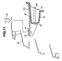
- the brackets or the like include support pieces 31 which are formed in a state to project from the four resin covering sections 27 in order that a front grille 39 is attached to the support pieces 31, as shown in Figs. 3 and 11 .
- Each support piece 31 is formed at its tip end section with an opening 41 into which a clip 40 for installation of the front grille 39 is fitted.
- the support piece 31 is further formed with an elongate opening 42 through which the surface of the upper wall W1 of the radiator core support upper section 13 is exposed in the rectangular shape.
- an additional support piece 32 for elastically supporting the power steering system oil cooler tube 6 is formed projecting from the inclined ribs 21, 22 corresponding to the right-side resin covering section 29 formed on the radiator core support lower section 14.
- a further support piece 33 is formed at the left side of the support piece 32.
- each of anchor sections 30 is formed through a through-hole formed at the bottom wall W3 of the radiator core support upper and lower sections 13, 14 in order to integrally connect the inclined ribs 21, 22 located inside the channel C and the resin covering section 27, 28, 29 located outside the channel C of the radiator core support upper and lower sections 13, 14.
- the resin covering section 27, 28, 29 is in a state to pierce the wall of the radiator core support upper and lower sections 13, 14, so as to be improved in installation rigidity to the radiator core support upper and lower sections 13, 14.
- Each anchor section 30 corresponds to or is directly integrally connected to the column-like struck portion 23 formed at the central part of the inclined rib 21, 22, the support piece 32 for the power steering system oil cooler tube 6, and the support piece 31 for the front grille 39, thereby improving the rigidity of the column-like struck portion 23 and the support pieces 31, 32.
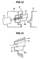
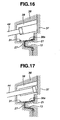
- Figs. 12 to 17 schematically illustrate the fragmentary sectional views of a part of the metallic mold 18 generally corresponding to the support piece 31 for the front grille 39.
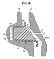
- Fig. 18 illustrates the fragmentary enlarged sectional view of a part of the metallic mold 18 generally corresponding to the resin-covering section 29 of the radiator core support lower section 14.
- the metallic mold includes the stationary mold 36.
- the movable mold 37 is provided to be horizontally moved relative to the stationary mold 36.
- a slide mold 38 is provided to be slidably movable in a direction crossing a direction in which the movable mold 37 moves.
- the slide mold 36 is installed to a cylinder 44 of a hydraulic coupling device 43, and movable relative to the cylinder 44.
- the slide mold 36 is biased in a direction far from the stationary mold 36 by a spring 45.
- a cavity space for forming the hood lock stay 15 and the like is formed among the stationary mold 36, the movable mold 37 and the slide mold 38.
- the slide mold 38 has a projection 38a corresponding to the elongate opening 42 through which the surface of the upper wall W1 of the radiator core support upper section 13 is exposed.
- the cylinder 44 of the hydraulic coupling device 43 is moved backward so that the slide mold 38 is fitted into the stationary mold 36, as shown in Fig. 13 .
- the radiator core support upper section 13 and the like as the metal parts of the radiator core support structure 1 are set in the cavity of the stationary mold 36, as shown in Fig. 14 .
- the side of the stationary mold 36 is provided with a magnet (not shown) which attracts and supports the radiator core upper section 13 at a certain position of the stationary mold 36.
- the magnet may be disposed to be movable and projectable over the surface of the stationary mold 36 under the action of a spring.
- the movable mold 37 is brought into contact or fit with the stationary mold 36 and the slide mold 38, as shown in Fig. 15 .
- synthetic resin is injected into the cavity space of the metallic mold 18, as shown in Fig. 16 .
- the upper surface of the radiator core support upper section 13 is pressed by the projection 38a of the slide mold 38, and consequently the upper surface portion of the radiator core support upper section 13 is prevented from deforming owing to the pressure of synthetic resin during injection molding.
- the part having the support piece 31 is of the resin covering section 27, so that the part does not contact with any section and therefore is unstable and in a free state.
- the projection 38a corresponding the elongate opening 42 is brought into contact with the part having the support piece 31, and therefore the upper surface portion of the radiator core support upper section 13 is prevented from being deformed under the pressure of injected synthetic resin.
- the cylinder 44 of the hydraulic coupling device 43 is moved forward, as shown in Fig. 17 .
- the slide mold 38 is simultaneously moved in the direction far from the stationary mold 36 under the action of the spring 45, so that the metallic mold 18 is returned to its state shown in Fig. 12 .
- Fig. 18 shows a state where the inclined ribs 21, 22 of the radiator core support lower section 14 are drawn out from the metallic mold 18. It will be understood that the inclined ribs 21, 22 of the radiator core support upper section 13 takes the similar state, and therefore illustration thereof is omitted for the purpose of simplicity of illustration.
- the struck portion 23 of the radiator core support lower section 14 and the radiator core support upper section 13 is located at the central part of each inclined rib 21, 22 and extends generally in the fore and aft direction of the vehicle.
- the struck portion 23 has the column-like shape and has a cross-sectional area which is larger than the thickness of each inclined rib 21, 22.
- the cross-sectional area of the struck portion 23 is larger than the cross-sectional area (defined by the thickness and the dimension corresponding to the diameter of the struck portion) of each inclined rib 21, 22.
- the struck portion 23 has a flat rear end face. This struck portion 23 is struck or pushed by an ejector pin 24 in order to extract the injection-molded inclined ribs 21, 22 from the metallic mold 18.
- the inclined rib 21, 22 is directly pushed through the struck portion 23 by the ejector pin 24, and therefore the inclined ribs 21, 22 can be prevented from being damaged in a state to be left in the metallic mold 18 during extraction of the inclined ribs 21, 22 from the metallic mold 18.
- the parts formed of synthetic resin are formed to be securely united with the parts formed of metal by injecting synthetic resin into the metallic mold 18, thereby producing the radiator core support structure 1.
- the radiator 8 and the like are assembled with the thus produced radiator core support structure 1 so as to be modularized.
- the side sections 17 formed of metal
- the opposite end sections of the radiator core support lower section 14 are installed respectively to the front end sections of the front side members 10 while the opposite end sections of the radiator core support upper section 13 are installed respectively to the front end sections (not shown) of the hood ridge panels 11.
- the hood lock stay 15 for connecting the radiator core support upper and lower sections 13, 14 is molded in the metallic mold 18 to be rigidly combined or united with the radiator core support upper and lower sections 13, 14 which are also put in the metallic mold 18.
- This hood lock stay 15 formed of synthetic resin removes causes for producing the torsional deformation and the assembly-dimensional error of the radiator core support structure 1, thus facilitating the above-discussed installation operation of the radiator support structure 1 to the vehicle body front structure 2.
- the rigidity of the connection of the hood lock stay 15 with the radiator core support lower section 14 can be improved so as to be endurable to a downward impact to be applied to the radiator core support lower section 14 from the hood lock stay 15 even though the hood lock stay 15 is formed of synthetic resin.
- the radiator core support structure 1 can be rigidly connected to the front side members 10 of the vehicle body. Further, the radiator core support upper section 13 and the radiator core support lower section 14 are formed of metal, and therefore the rigidity of the whole radiator core support structure 1 can become high thereby improving the noise and vibration characteristics and the drivability of the vehicle.
- Fig. 19 illustrates an essential part of another embodiment of the radiator core support structure 1, similar to the embodiment shown in Figs. 1 to 18 .
- each column-like struck portion 23 is formed at its rear end face with a depression or hollow 23a which is generally coaxial with the struck portion 23 and extends along the axis of the struck portion 23 to reach a position near the bottom wall W3 of the radiator core support lower section 14 having the generally C-shaped cross-section, the position being slightly separate from the bottom wall W3.
- the ejector pin 24 is provided at its tip end portion with a cylindrical projection 24a which is coaxial with and extends along the axis of the ejector pin 24.
- the cylindrical projection 24a is smaller in diameter than the ejector pin 24 and insertable into the hollow 23a of the struck portion 23.
- the projection 24a is smaller in axial length than the hollow 23a of the struck portion 23, so that it is sufficient that the projection 24a is insertable to the inlet part of the hollow 23a.
- the projection 24a of the ejector pin 24 is insertable into the hollow 23a of the struck portion 23, a locational shift of the inclined ribs 21, 22 can be prevented when the struck portion 23 is pushed by the ejector pin 24 while saving a raw material and lightening the weight of the radiator core support structure 1 by amounts corresponding to the hollow 23a formed in the struck portion 23.
- the reinforcement ribs 21, 22 have been shown and described as the reinforcement ribs, it will be understood that the reinforcement ribs formed inside the channel C of the radiator core support upper and lower sections 13, 14 are not limited to the inclined ribs 21, 22, so that each of the reinforcement ribs may be formed extending perpendicular to the longitudinal direction of the radiator core upper and lower sections 13, 14.
- the struck portion 23 has been shown and described as being formed as having the generally column-like shape, it will be appreciated that the struck portion 23 may have a rectangular cross-section. Further, two struck portions 23 may be formed on each reinforcement rib.
- the present teaching does not exclude that the ejector pin 24 pushes the other portions than the struck portion 23, so that the ejector pin 24 may push not only the struck portion 23 but also the other portions of each reinforcement rib.
Landscapes
- Engineering & Computer Science (AREA)
- Mechanical Engineering (AREA)
- Chemical & Material Sciences (AREA)
- Combustion & Propulsion (AREA)
- Transportation (AREA)
- Architecture (AREA)
- Structural Engineering (AREA)
- Manufacturing & Machinery (AREA)
- Body Structure For Vehicles (AREA)
- Cooling, Air Intake And Gas Exhaust, And Fuel Tank Arrangements In Propulsion Units (AREA)
Claims (17)
- Kühlerkern- Trägerstruktur für ein Fahrzeug, die aufweist:einen oberen Kühlerkern- Trägerabschnitt (13), der sich im Wesentlichen entlang einer Richtung der Breite des Fahrzeuges erstreckt;einen unteren Kühlerkern- Trägerabschnitt (14), der sich im Wesentlichen entlang einer Richtung der Breite des Fahrzeuges erstreckt und unter dem oberen Kühlerkern- Trägerabschnitt (13) angeordnet ist, wobei der obere Kühlerkern- Trägerabschnitt (13) und der untere Kühlerkern- Trägerabschnitt (14) aus Metall gebildet ist und einen offenen, schlaufenförmig geformten Querschnitt hat, der nach hinten geöffnet ist, um einen Kanal (C) zu bilden, der sich in einer Längsrichtung des oberen Kühlerkern- Trägerabschnittes (13) und des unteren Kühlerkern- Trägerabschnittes (14) erstreckt, wobei der obere Kühlerkern- Trägerabschnitt (13) und der untere Kühlerkern- Trägerabschnitt (14) eine obere Wand (W1) und eine untere Wand (W2) haben;eine Haubenverriegelungsträger (15), der sich im Wesentlichen vertikal erstreckt, undeinen Verstärkungsabschnitt (21, 22, 23), gebildet aus Kunststoff und fest innerhalb des Kanals (C) des oberen Kühlerkern- Trägerabschnittes (13) und des unteren Kühlerkern- Trägerabschnittes (14) angeordnet, wobei der Verstärkungsabschnitt (21, 22, 23) sich kontinuierlich in einer Längsrichtung des oberen Kühlerkern- Trägerabschnittes (13) und des unteren Kühlerkern- Trägerabschnittes (14) erstreckt, wobei der Haubenverriegelungsträger (15) einen im Wesentlichen mittleren Teil des oberen Kühlerkern- Trägerabschnittes (13) und einen im Wesentlichen mittleren Teil des unteren Kühlerkern- Trägerabschnittes (14) verbindet, wobei der im Wesentlichen mittlere Teil in der Richtung der Breite des Fahrzeuges liegt, der Haubenverriegelungsträger (15) aus Kunststoff gebildet und in einer metallischen Form (18) geformt ist, in der der obere Kühlerkern- Trägerabschnitt (13) und der untere Kühlerkern- Trägerabschnitt (14) angeordnet sind.
- Kühlerkern- Trägerstruktur für ein Fahrzeug nach Anspruch 1, wobei der Verstärkungsabschnitt (21, 22, 23) eine Mehrzahl von Verstärkungsrippen (21, 22) aufweist, gebildet aus dem Kunststoff und fest innerhalb des Kanales (C) des oberen Kühlerkern- Trägerabschnittes (13) und des unteren Kühlerkern- Trägerabschnittes (14) angeordnet, die Verstärkungsrippen (21, 22) sich kontinuierlich in einer Längsrichtung von dem oberen Kühlerkern- Trägerabschnitt (13) und dem unteren Kühlerkern- Trägerabschnitt (14) erstrecken, jede Verstärkungsrippe sich zur festen Verbindungen der oberen Wand (W1) und der unteren Wand (W2) von dem oberen Kühlerkern- Trägerabschnitt (13) und dem unteren Kühlerkern- Trägerabschnitt (14) erstreckt; und
einem Entnahmeabschnitt (23), der einstückig an einem Teil jeder Verstärkungsrippe gebildet ist, um durch einen Auswerferstift (24) ausgehoben zu werden, zum Entfernen der Kühlerkern- Trägerstruktur (1) aus der Metallform (18). - Kühlerkern- Trägerstruktur nach Anspruch 2, wobei der Entnahmeabschnitt (23) im Wesentlichen an einem mittleren Abschnitt jeder Verstärkungsrippe (21, 22) gebildet ist, ein Teil des Entnahmeabschnittes (23) im Wesentlichen an einer Längsmitte einer Kante jeder Verstärkungsrippe (21, 22) angeordnet ist.
- Kühlerkern- Trägerstruktur nach Anspruch 2 oder 3, wobei der Entnahmeabschnitt (23) in einer säulenartigen Form ist und sich erstreckt, um eine Bodenwand (W3) des oberen Kühlerkern- Trägerabschnittes (13) und des unteren Kühlerkern- Trägerabschnittes (14) zu erreichen, die Bodenwand (W3) angeordnet ist, um die obere Wand (W1) und die untere Wand (W2) zu verbinden, wobei der Entnahmeabschnitt (23) eine Querschnittsfläche größer als eine Dicke jeder Verstärkungsrippe (21, 22) hat.
- Kühlerkern- Trägerstruktur nach zumindest einem der Ansprüche 2 bis 4, wobei der Entnahmeabschnitt (23) durch einen Auswerferstift (24) ausgehoben wird, zum Entfernen der Kühlerkern- Trägerstruktur (1) aus der Metallform (18).
- Kühlerkern- Trägerstruktur nach Anspruch 5, wobei der Entnahmeabschnitt (23) mit einem Hohlraum (23a) gebildet ist, der einen Durchmesser kleiner als jener des Entnahmeabschnittes (23) hat, der Hohlraum (23a) sich in einer axialen Richtung des Entnahmeabschnittes (23) erstreckt und eine axiale Länge hat, wobei der Auswerferstift (24) einen Vorsprung (24a) hat, der von einem Spitzenende des Auswerferstiftes (24) vorspringt und einen Durchmesser kleiner als jenen des Auswerferstiftes (24) hat, um in den Hohlraum (23a) des Entnahmeabschnittes (23) einsetzbar zu sein.
- Kühlerkern- Trägerstruktur nach zumindest einem der Ansprüche 2 bis 6, wobei die Verstärkungsrippen (21, 22) geneigte Rippen sind, die im Verhältnis zu einer vertikalen Ebene rechtwinklig zu der oberen Wand (W1) und der unteren Wand (W2) geneigt sind, die Verstärkungsrippen (21, 22) zwischen der oberen Wand (W1) und der unteren Wand (W2) des oberen Kühlerkern- Trägerabschnittes (13) und des unteren Kühlerkern- Trägerabschnittes (14) angeordnet sind und sich kontinuierlich in einem Zick- Zack- Muster im Wesentlichen entlang der Richtung der Breite des Fahrzeuges erstrecken.
- Kühlerkern- Trägerstruktur nach Anspruch 7, wobei jede der geneigten Verstärkungsrippen (21, 22) einen Winkel hat, der von 30° bis 60° im Verhältnis zu einer Längsrichtung des oberen Kühlerkern- Trägerabschnittes (13) und des unteren Kühlerkern- Trägerabschnittes (14) reicht.
- Kühlerkern- Trägerstruktur nach zumindest einem der Ansprüche 2 bis 8, wobei der obere Kühlerkern- Trägerabschnitt (13) aus Metall gebildet ist, wobei der die Kühlerkern- Trägerstruktur (1) außerdem einen Haubenverriegelungs- Installationsabschnitt (16) aufweist, der aus Metall gebildet ist und an einem seitlichen mittleren Teil des Kühlerkern- Trägerabschnittes (13) gebildet ist.
- Kühlerkern- Trägerstruktur nach Anspruch 9, wobei ein gebogener Abschnitt (26) an einem unteren Endteil des Haubenschloss - Installationsabschnittes (16) gebildet und in einem oberen Endabschnitt des Haubenverriegelungsträgers (15), gebildet aus Kunststoff, eingebettet ist.
- Kühlerkern- Trägerstruktur nach zumindest einem der Ansprüche 2 bis 10, wobei der untere Kühlerkern- Trägerabschnitt (14) aus Metall gebildet ist, wobei die Kühlerkern- Trägerstruktur (1) außerdem Seitenabschnitte (17), gebildet aus Metall, aufweist, die Seitenabschnitte (17) an gegenüberliegenden Endabschnitten des unteren Kühlerkern- Trägerabschnittes (14) gebildet sind, die Seitenabschnitte (17) vorgesehen sind, um jeweils mit den vorderen Seitenteilen (10) einer Fahrzeugkarosserie verbunden zu werden.
- Kühlerkern- Trägerstruktur nach Anspruch 11, die außerdem Säulenabschnitte (19) aufweist, von denen jede innenbords jedes Seitenabschnittes (17) angeordnet und vorgesehen ist, um eine Innenbord- Seitenkante jedes Seitenabschnittes (17), den oberen Kühlerkern- Trägerabschnitt (13) und den unteren Kühlerkern-Trägerabschnitt (14) steif zu verbinden, wobei die Stützabschnitte (19) einstückig fortgesetzt mit den Verstärkungsrippen (21, 22) sind.
- Kühlerkern- Trägerstruktur nach Anspruch 11 oder 12, außerdem mit Lampeninstallationsabschnitten (20), die an gegenüberliegenden Endabschnitten des oberen Kühlerkern- Trägerabschnittes (13) angeordnet sind, wobei jeder Lampeninstallationsabschnitt (13) vorgesehen ist einen der gegenüberliegenden Endabschnitte des oberen Kühlerkern- Trägerabschnittes (13) und den Seitenabschnitt (17) steif zu verbinden, wobei die Lampeninstallationsabschnitte (20) einstückig fortgesetzt mit den Verstärkungsrippen (21, 22) gebildet sind.
- Kühlerkern- Trägerstruktur nach zumindest einem der Ansprüche 2 bis 13, die außerdem aufweist einen Abdeckabschnitt (27, 28, 29), gebildet aus Kunststoff, und durch einen Ankerabschnitt (30) mit einem Teil der Verstärkungsrippen (21, 22) fortgesetzt, wobei der Abdeckabschnitt (27,28, 29) eine Außenoberfläche des oberen Kühlerkern- Trägerabschnitt (13) und des unteren Kühlerkern- Trägerabschnittes (14) abdeckt und sich von einer Außenoberfläche einer oberen Wand (W1) zu der Außenoberfläche der unteren Wand (W2) des oberen Kühlerkern-Trägerabschnittes (13) und des unteren Kühlerkern- Trägerabschnittes (14) erstreckt, wobei der Ankerabschnitt (30) entsprechend des Entnahmeabschnittes (23) angeordnet ist und eine Wand des oberen Kühlerkern- Trägerabschnittes (13) und des unteren Kühlerkern- Trägerabschnittes (14) durchdringt.
- Kühlerkern- Trägerstruktur für ein Fahrzeug nach zumindest einem der Ansprüche 2 bis 13, mit außerdem einem Abdeckabschnitt (27, 28, 29), gebildet aus Kunststoff und fortgesetzt mit dem Verstärkungsabschnitt (21, 22, 23), wobei der Abdeckabschnitt (27, 28, 29) eine Außenoberfläche des oberen Kühlerkern- Trägerabschnittes (13) und des unteren Kühlerkern- Trägerabschnittes (14) abdeckt und sich von einer Außenoberfläche einer oberen Wand (W1) zu der Außenoberfläche der unteren Wand (W2) des oberen Kühlerkern- Trägerabschnittes (13) und des unteren Kühlerkern- Trägerabschnittes (14) erstreckt, der Abdeckabschnitt (27, 28, 29) mit zumindest einer Öffnung (42) gebildet ist, angeordnet entsprechend zumindest einer der oberen Wand (W1) oder der unteren Wand (W2), wobei eine Oberfläche der zumindest einen der oberen Wand (W1) oder der unteren Wand (W2) durch die zumindest eine Öffnung (42) freigelegt ist.
- Kühlerkern- Trägerstruktur nach Anspruch 15, wobei der Abdeckabschnitt (27, 28, 29) durch einen Ankerabschnitt (30) mit dem Verstärkungsabschnitt (21, 22, 23) fortgesetzt ist, der Ankerabschnitt (30) entsprechend des Abdeckabschnittes (27, 28, 29) des oberen Kühlerkern- Trägerabschnittes (13) und des unteren Kühlerkern- Trägerabschnittes (14) angeordnet ist und eine Wand des oberen Kühlerkern- Trägerabschnittes (13) und des unteren Kühlerkern- Trägerabschnittes (14) durchdringt.
- Kühlerkern- Trägerstruktur nach zumindest einem der Ansprüche 14 bis 16, außerdem mit einem Trägerstück (31) zur Installation eines Vordergrills (39), wobei das Trägerstück (31) einstückig mit und vorspringend von dem Abdeckabschnitt (27, 28, 29) ist.
Priority Applications (1)
| Application Number | Priority Date | Filing Date | Title |
|---|---|---|---|
| DE60109114.0T DE60109114T3 (de) | 2000-12-07 | 2001-12-06 | Tragstruktur für Kraftfahrzeugkühlerblock |
Applications Claiming Priority (4)
| Application Number | Priority Date | Filing Date | Title |
|---|---|---|---|
| JP2000373015 | 2000-12-07 | ||
| JP2000373015A JP4025010B2 (ja) | 2000-12-07 | 2000-12-07 | 車両用ラジエータコアサポート構造及びその成形用金型 |
| JP2000372897 | 2000-12-07 | ||
| JP2000372897A JP3993382B2 (ja) | 2000-12-07 | 2000-12-07 | 車両用ラジエータコアサポート構造 |
Publications (3)
| Publication Number | Publication Date |
|---|---|
| EP1213207A1 EP1213207A1 (de) | 2002-06-12 |
| EP1213207B1 EP1213207B1 (de) | 2005-03-02 |
| EP1213207B2 true EP1213207B2 (de) | 2014-11-26 |
Family
ID=26605423
Family Applications (1)
| Application Number | Title | Priority Date | Filing Date |
|---|---|---|---|
| EP01129015.2A Expired - Lifetime EP1213207B2 (de) | 2000-12-07 | 2001-12-06 | Tragstruktur für Kraftfahrzeugkühlerblock |
Country Status (3)
| Country | Link |
|---|---|
| US (1) | US6715573B2 (de) |
| EP (1) | EP1213207B2 (de) |
| DE (1) | DE60109114T3 (de) |
Families Citing this family (53)
| Publication number | Priority date | Publication date | Assignee | Title |
|---|---|---|---|---|
| JP2001121941A (ja) * | 1999-10-28 | 2001-05-08 | Denso Corp | 熱交換器の車両搭載構造 |
| DE60105948T3 (de) * | 2000-11-29 | 2009-07-09 | Calsonic Kansei Corp. | Trägerstruktur für Kfz-Kühleranordnung |
| FR2833235B1 (fr) * | 2001-12-11 | 2004-08-13 | Plastic Omnium Cie | Piece de structure avant de vehicule automobile munie d'un convergent et face avant technique constituant une telle piece de structure |
| CN1520365A (zh) * | 2002-03-01 | 2004-08-11 | �ղ��Զ�����ʽ���� | 车辆前部车身结构及车辆前部车身结构的组装方法 |
| WO2004011315A2 (en) * | 2002-07-25 | 2004-02-05 | General Electric Company | Method of attaching plastic to a metal section and part made thereby |
| BR0317607A (pt) * | 2002-12-19 | 2005-11-29 | Gen Electric | Módulo de extremidade frontal |
| JP4105001B2 (ja) * | 2003-02-10 | 2008-06-18 | カルソニックカンセイ株式会社 | フードロックステイの結合構造 |
| FR2851221B1 (fr) * | 2003-02-18 | 2005-08-05 | Plastic Omnium Cie | Face avant technique de vehicule automobile, comportant une traverse superieure renforcee |
| JP4349115B2 (ja) * | 2003-02-26 | 2009-10-21 | 日産自動車株式会社 | フレーム車の車体前部構造 |
| DE20310656U1 (de) * | 2003-07-11 | 2003-09-11 | Hella-Behr Fahrzeugsysteme GmbH, 59557 Lippstadt | Hybridbauteil für Kraftfahrzeuge |
| JP4299605B2 (ja) * | 2003-07-23 | 2009-07-22 | カルソニックカンセイ株式会社 | 金属板部材の樹脂インサート成形治具およびそれを用いた金属板部材の樹脂インサート成形方法 |
| FR2858798B1 (fr) * | 2003-08-11 | 2006-02-03 | Plastic Omnium Cie | Traverse de face avant technique d'un vehicule automobile, face avant technique et support de module de refroidissement munis d'une telle traverse |
| JP4586477B2 (ja) * | 2003-12-22 | 2010-11-24 | マツダ株式会社 | シュラウドの支持構造および組付け方法 |
| FR2866306B1 (fr) | 2004-02-17 | 2006-05-26 | Valeo Thermique Moteur Sa | Structure composite en metal et matiere plastique, en particulier pour une face avant de vehicule automobile. |
| KR100550621B1 (ko) * | 2004-05-17 | 2006-02-09 | 현대모비스 주식회사 | 캐리어 구조 |
| JP2005349923A (ja) * | 2004-06-09 | 2005-12-22 | Calsonic Kansei Corp | ヘッドランプおよびバンパフェイシアサイド部の取付構造 |
| JP4506577B2 (ja) * | 2004-09-21 | 2010-07-21 | トヨタ自動車株式会社 | 車両前部構造 |
| US7243986B2 (en) * | 2004-10-19 | 2007-07-17 | Ford Global Technologies, Llc | Spot-welded joint for hydroformed members |
| FR2879155B1 (fr) * | 2004-12-09 | 2008-06-06 | Valeo Thermique Moteur Sas | Support de face avant de vehicule automobile comportant une cavite integree. |
| FR2884214B1 (fr) * | 2005-04-07 | 2007-07-06 | Faurecia Bloc Avant | Element structurel pour vehicule automobile, vehicule automobile correspondant, et procede de fabrication d'un tel element structurel. |
| JP2006298167A (ja) * | 2005-04-20 | 2006-11-02 | Calsonic Kansei Corp | フードロックの固定構造 |
| KR20060115243A (ko) * | 2005-05-04 | 2006-11-08 | 현대모비스 주식회사 | 캐리어 제조방법 |
| US7410019B2 (en) * | 2005-06-10 | 2008-08-12 | Yamaha Motor Manufacturing Corporation Of America | Bracket assembly for all-terrain vehicle |
| JP5030421B2 (ja) * | 2005-12-13 | 2012-09-19 | カルソニックカンセイ株式会社 | ラジエータコアサポート |
| US7926870B2 (en) * | 2006-05-26 | 2011-04-19 | Dow Global Technologies Llc | Modular assembly for a vehicle |
| DE102006047419A1 (de) | 2006-10-06 | 2008-04-10 | Daimler Ag | Trägerteil für ein Frontendmodul eines Personenkraftwagens |
| JP5457623B2 (ja) * | 2006-12-28 | 2014-04-02 | カルソニックカンセイ株式会社 | 樹脂成形品 |
| US7571957B2 (en) * | 2007-02-01 | 2009-08-11 | Magna International | Component integration panel system with closed box section |
| FR2915129B1 (fr) * | 2007-04-19 | 2011-01-14 | Inoplast Sa | Piece hybride, moule et procede pour la fabrication de cette piece. |
| JP5078825B2 (ja) * | 2008-03-26 | 2012-11-21 | カルソニックカンセイ株式会社 | ラジエータコアサポート |
| US8196978B2 (en) * | 2008-04-18 | 2012-06-12 | Hyundai Motor Company | Carrier and front end module system |
| US8047603B2 (en) * | 2008-06-13 | 2011-11-01 | Sabic Innovative Plastics Ip B.V. | Plastic crush countermeasure for vehicles |
| BRPI0921447B8 (pt) * | 2008-11-07 | 2020-12-08 | Zephyros Inc | estrutura de reforço híbrido |
| DE102009052110A1 (de) | 2009-11-05 | 2011-05-12 | Faurecia Innenraum Systeme Gmbh | Kraftfahrzeug-Frontend |
| WO2012067059A1 (ja) * | 2010-11-19 | 2012-05-24 | スズキ株式会社 | 車体前部の構造 |
| CN102695632B (zh) * | 2010-12-21 | 2014-10-15 | 丰田自动车株式会社 | 保险杠组件 |
| DE102011116208B4 (de) * | 2011-10-14 | 2021-07-15 | Daimler Ag | Frontendmodul |
| US9199669B2 (en) * | 2013-03-12 | 2015-12-01 | Nissan North America, Inc. | Vehicle front end structure |
| TW201442844A (zh) * | 2013-05-10 | 2014-11-16 | Hon Hai Prec Ind Co Ltd | 模具斜梢結構以及注射成型模具 |
| JP5968853B2 (ja) * | 2013-10-25 | 2016-08-10 | 豊田鉄工株式会社 | ラジエータコアサポート |
| DE102014006886A1 (de) * | 2014-05-09 | 2015-11-12 | GM Global Technology Operations LLC (n. d. Gesetzen des Staates Delaware) | Verfahren zur Herstellung einer Sitzlehnenstruktur eines Fahrzeugsitzes |
| US9863719B2 (en) | 2014-09-26 | 2018-01-09 | Caterpillar Inc. | Heat exchanger support assembly |
| JP6109271B2 (ja) * | 2015-02-06 | 2017-04-05 | 株式会社神戸製鋼所 | 接合構造体、及び接合構造体の製造方法 |
| FR3037553B1 (fr) * | 2015-06-22 | 2019-05-17 | Valeo Systemes Thermiques | Structure de support pour un module de face avant d'un vehicule automobile et module de face avant comprenant ladite structure de support |
| DE102017215092A1 (de) * | 2017-08-29 | 2019-02-28 | Elringklinger Ag | Formbauteil, Sitz und Verfahren zur Herstellung eines Formbauteils |
| US10807650B2 (en) * | 2017-10-11 | 2020-10-20 | Ford Global Technologies, Llc | Hood latch support beam |
| CN107985418B (zh) * | 2017-12-11 | 2020-03-17 | 重庆长安汽车股份有限公司 | 一种汽车前上构件总成 |
| US10808657B2 (en) * | 2018-02-02 | 2020-10-20 | Ford Global Technologies, Llc | Vehicle component with an accessory mounting feature and a method and tool for forming |
| US10479296B2 (en) * | 2018-03-02 | 2019-11-19 | Ford Global Technologies, Llc | Smart grille assembly and modular grille assembly system for a motor vehicle |
| JP7369808B2 (ja) * | 2022-02-15 | 2023-10-26 | 本田技研工業株式会社 | 車両前部構造 |
| CN114932655B (zh) * | 2022-04-25 | 2024-02-20 | 日善电脑配件(嘉善)有限公司 | 薄框架注塑植入取出装置、方法及设备 |
| CN115520282B (zh) * | 2022-10-31 | 2024-11-22 | 重庆长安汽车股份有限公司 | 一种汽车前上构件结构 |
| CN119840732B (zh) * | 2023-10-17 | 2025-11-14 | 张家港长城汽车研发有限公司 | 机舱前部传力结构及车辆 |
Family Cites Families (23)
| Publication number | Priority date | Publication date | Assignee | Title |
|---|---|---|---|---|
| US5190803A (en) * | 1988-11-25 | 1993-03-02 | Bayer Aktiengesellschaft | Structural shell with reinforcing ribs connected via perforations |
| DE3839855A1 (de) | 1988-11-25 | 1990-05-31 | Bayer Ag | Leichtbauteil |
| JP2933702B2 (ja) * | 1989-12-21 | 1999-08-16 | マツダ株式会社 | 自動車の前部車体構造およびその組立方法 |
| JPH05170135A (ja) * | 1991-12-18 | 1993-07-09 | Mazda Motor Corp | 自動車の前部車体構造 |
| JP2596056Y2 (ja) * | 1993-01-25 | 1999-06-07 | 富士重工業株式会社 | 車両のフロントエンド部モジュールキャリア構造 |
| FR2719014B1 (fr) * | 1994-04-25 | 1996-07-12 | Plastic Omnium Cie | Face avant technique de véhicule automobile. |
| US6168226B1 (en) * | 1994-05-19 | 2001-01-02 | Henkel Corporation | Composite laminate automotive structures |
| US5575526A (en) * | 1994-05-19 | 1996-11-19 | Novamax Technologies, Inc. | Composite laminate beam for radiator support |
| US5884960A (en) * | 1994-05-19 | 1999-03-23 | Henkel Corporation | Reinforced door beam |
| JPH10264855A (ja) * | 1997-03-26 | 1998-10-06 | Aisin Seiki Co Ltd | 車両フロントエンドモジュール構造 |
| FR2783794B1 (fr) * | 1998-09-30 | 2001-01-26 | Valeo Thermique Moteur Sa | Facade avant composite metal/plastique surmoulee pour vehicule automobile |
| FR2783795B1 (fr) * | 1998-09-30 | 2001-01-26 | Valeo Thermique Moteur Sa | Facade avant composite metal/plastique renforcee pour vehicule automobile |
| FR2783796B1 (fr) * | 1998-09-30 | 2001-02-23 | Valeo Thermique Moteur Sa | Facade avant composite metal/plastique renforcee surmoulee pour vehicule automobile |
| FR2787410B1 (fr) * | 1998-12-21 | 2001-03-09 | Ecia Equip Composants Ind Auto | Face avant et agencement de cette face avant dans un vehicule automobile |
| JP2001001941A (ja) * | 1999-06-23 | 2001-01-09 | Nissan Motor Co Ltd | 樹脂製ラジエータコアサポート構造およびその成形型 |
| US6634702B1 (en) * | 1999-06-23 | 2003-10-21 | Dynamit Nobel Kunstsoff Gmbh | Front-end module for a motor vehicle |
| FR2798355B1 (fr) * | 1999-09-15 | 2001-12-14 | Valeo Thermique Moteur Sa | Element de structure composite, notamment support de face avant pour vehicule |
| US6357821B1 (en) * | 1999-10-13 | 2002-03-19 | Ford Global Technologies, Inc. | Lamp can and radiator support assembly |
| US6502653B1 (en) * | 1999-10-13 | 2003-01-07 | Ford Global Technologies, Inc. | Multi-functional radiator support assembly |
| DE60033630T2 (de) * | 1999-10-20 | 2007-11-22 | Denso Corp., Kariya | Frontwand |
| FR2800030B1 (fr) * | 1999-10-25 | 2002-01-11 | Plastic Omnium Cie | Piece de structure de vehicule automobile, notamment face avant technique |
| JP4320899B2 (ja) * | 2000-02-03 | 2009-08-26 | 株式会社デンソー | フロントエンドパネル |
| US6622808B2 (en) * | 2000-04-10 | 2003-09-23 | Denso Corporation | Resin molding for vehicle use and manufacturing method thereof |
-
2001
- 2001-12-06 EP EP01129015.2A patent/EP1213207B2/de not_active Expired - Lifetime
- 2001-12-06 DE DE60109114.0T patent/DE60109114T3/de not_active Expired - Lifetime
- 2001-12-07 US US10/005,919 patent/US6715573B2/en not_active Expired - Lifetime
Non-Patent Citations (3)
| Title |
|---|
| B. KOS ET AL.: "Interieur & Karosserie", vol. 3, 1999, CARL HANSER VERLAG, MÜNCHEN, pages: 82 - 86 † |
| H. GOLDBACH ET AL.: "Fachzeitschrift Kunststoffe 87", vol. 9, 1997, CARL HANSER VERLAG, MÜNCHEN, pages: 1133 - 1138 † |
| U. STEUER ET AL.: "The Hybrid Front End of the Audi A6", VDI CONFERENCE, 1999, pages 3 - 26 † |
Also Published As
| Publication number | Publication date |
|---|---|
| DE60109114D1 (de) | 2005-04-07 |
| US6715573B2 (en) | 2004-04-06 |
| EP1213207A1 (de) | 2002-06-12 |
| US20020084122A1 (en) | 2002-07-04 |
| DE60109114T3 (de) | 2015-01-08 |
| EP1213207B1 (de) | 2005-03-02 |
| DE60109114T2 (de) | 2005-07-21 |
Similar Documents
| Publication | Publication Date | Title |
|---|---|---|
| EP1213207B1 (de) | Tragstruktur für Kraftfahrzeugkühlerblock | |
| EP1211164B1 (de) | Trägerstruktur für Kfz-Kühleranordnung | |
| EP1211163B1 (de) | Trägerstruktur für Kfz-Kühleranordnung | |
| US6540037B2 (en) | Vehicle front end panel | |
| US6412855B1 (en) | Overmoulded reinforced metal/plastic composite front panel for motor vehicle | |
| US20070257497A1 (en) | Vehicle bumper beam constructed of metal and plastic | |
| KR20010083173A (ko) | 차체 구조 | |
| US6216810B1 (en) | Front end module structure of vehicle | |
| US11351858B2 (en) | Stiffness reinforcement structure for fuel tank of vehicle | |
| JP2007203776A (ja) | 自動車の前部構造 | |
| KR102884645B1 (ko) | 차량의 차체 루프 | |
| JP3993382B2 (ja) | 車両用ラジエータコアサポート構造 | |
| US7534382B2 (en) | Insert injection molding method and jig | |
| JP5067139B2 (ja) | 自動車の前部構造 | |
| JP4285247B2 (ja) | 熱交換器 | |
| JP2002220014A (ja) | 自動車のバンパー構造 | |
| JPH056402Y2 (de) | ||
| JP5178174B2 (ja) | ワイヤハーネス用プロテクタ | |
| KR100716354B1 (ko) | 자동차의 프론트 범퍼커버의 마운팅 구조 | |
| KR102701585B1 (ko) | 차량용 범퍼 스태이의 충격흡수홈 성형방법 | |
| JP4960073B2 (ja) | 車両内装部材 | |
| CN203472153U (zh) | 树脂部件的接合部构造 | |
| JP7829342B2 (ja) | ラジエータグリル及びラジエータグリル製造方法 | |
| JPH11180342A (ja) | フロントエンドパネル及びその製造方法並びに製造用金型 | |
| JP4025010B2 (ja) | 車両用ラジエータコアサポート構造及びその成形用金型 |
Legal Events
| Date | Code | Title | Description |
|---|---|---|---|
| PUAI | Public reference made under article 153(3) epc to a published international application that has entered the european phase |
Free format text: ORIGINAL CODE: 0009012 |
|
| 17P | Request for examination filed |
Effective date: 20011206 |
|
| AK | Designated contracting states |
Kind code of ref document: A1 Designated state(s): AT BE CH CY DE DK ES FI FR GB GR IE IT LI LU MC NL PT SE TR |
|
| AX | Request for extension of the european patent |
Free format text: AL;LT;LV;MK;RO;SI |
|
| AKX | Designation fees paid |
Designated state(s): DE FR GB |
|
| 17Q | First examination report despatched |
Effective date: 20030702 |
|
| GRAP | Despatch of communication of intention to grant a patent |
Free format text: ORIGINAL CODE: EPIDOSNIGR1 |
|
| GRAS | Grant fee paid |
Free format text: ORIGINAL CODE: EPIDOSNIGR3 |
|
| GRAA | (expected) grant |
Free format text: ORIGINAL CODE: 0009210 |
|
| AK | Designated contracting states |
Kind code of ref document: B1 Designated state(s): DE FR GB |
|
| REG | Reference to a national code |
Ref country code: GB Ref legal event code: FG4D |
|
| REG | Reference to a national code |
Ref country code: IE Ref legal event code: FG4D |
|
| REF | Corresponds to: |
Ref document number: 60109114 Country of ref document: DE Date of ref document: 20050407 Kind code of ref document: P |
|
| PLBI | Opposition filed |
Free format text: ORIGINAL CODE: 0009260 |
|
| ET | Fr: translation filed | ||
| PLAX | Notice of opposition and request to file observation + time limit sent |
Free format text: ORIGINAL CODE: EPIDOSNOBS2 |
|
| 26 | Opposition filed |
Opponent name: HBPO GMBH / FAURECIA INNENRAUM SYSTEME GMBH Effective date: 20051201 |
|
| PLAF | Information modified related to communication of a notice of opposition and request to file observations + time limit |
Free format text: ORIGINAL CODE: EPIDOSCOBS2 |
|
| PLAF | Information modified related to communication of a notice of opposition and request to file observations + time limit |
Free format text: ORIGINAL CODE: EPIDOSCOBS2 |
|
| PLBB | Reply of patent proprietor to notice(s) of opposition received |
Free format text: ORIGINAL CODE: EPIDOSNOBS3 |
|
| PLAY | Examination report in opposition despatched + time limit |
Free format text: ORIGINAL CODE: EPIDOSNORE2 |
|
| PLAH | Information related to despatch of examination report in opposition + time limit modified |
Free format text: ORIGINAL CODE: EPIDOSCORE2 |
|
| PLAB | Opposition data, opponent's data or that of the opponent's representative modified |
Free format text: ORIGINAL CODE: 0009299OPPO |
|
| PLBC | Reply to examination report in opposition received |
Free format text: ORIGINAL CODE: EPIDOSNORE3 |
|
| R26 | Opposition filed (corrected) |
Opponent name: HBPO GMBH / FAURECIA INNENRAUM SYSTEME GMBH Effective date: 20051201 |
|
| REG | Reference to a national code |
Ref country code: GB Ref legal event code: 746 Effective date: 20090924 |
|
| PLAB | Opposition data, opponent's data or that of the opponent's representative modified |
Free format text: ORIGINAL CODE: 0009299OPPO |
|
| R26 | Opposition filed (corrected) |
Opponent name: HBPO GMBH / FAURECIA INNENRAUM SYSTEME GMBH Effective date: 20051201 |
|
| PUAH | Patent maintained in amended form |
Free format text: ORIGINAL CODE: 0009272 |
|
| STAA | Information on the status of an ep patent application or granted ep patent |
Free format text: STATUS: PATENT MAINTAINED AS AMENDED |
|
| 27A | Patent maintained in amended form |
Effective date: 20141126 |
|
| AK | Designated contracting states |
Kind code of ref document: B2 Designated state(s): DE FR GB |
|
| REG | Reference to a national code |
Ref country code: DE Ref legal event code: R102 Ref document number: 60109114 Country of ref document: DE |
|
| REG | Reference to a national code |
Ref country code: DE Ref legal event code: R102 Ref document number: 60109114 Country of ref document: DE Effective date: 20141126 |
|
| REG | Reference to a national code |
Ref country code: FR Ref legal event code: PLFP Year of fee payment: 15 |
|
| REG | Reference to a national code |
Ref country code: FR Ref legal event code: PLFP Year of fee payment: 16 |
|
| PGFP | Annual fee paid to national office [announced via postgrant information from national office to epo] |
Ref country code: DE Payment date: 20161129 Year of fee payment: 16 Ref country code: FR Payment date: 20161111 Year of fee payment: 16 Ref country code: GB Payment date: 20161130 Year of fee payment: 16 |
|
| REG | Reference to a national code |
Ref country code: DE Ref legal event code: R119 Ref document number: 60109114 Country of ref document: DE |
|
| GBPC | Gb: european patent ceased through non-payment of renewal fee |
Effective date: 20171206 |
|
| REG | Reference to a national code |
Ref country code: FR Ref legal event code: ST Effective date: 20180831 |
|
| PG25 | Lapsed in a contracting state [announced via postgrant information from national office to epo] |
Ref country code: DE Free format text: LAPSE BECAUSE OF NON-PAYMENT OF DUE FEES Effective date: 20180703 Ref country code: FR Free format text: LAPSE BECAUSE OF NON-PAYMENT OF DUE FEES Effective date: 20180102 |
|
| PG25 | Lapsed in a contracting state [announced via postgrant information from national office to epo] |
Ref country code: GB Free format text: LAPSE BECAUSE OF NON-PAYMENT OF DUE FEES Effective date: 20171206 |