EP1211568A2 - Vorrichtung und Verfahren zur passgenauen Ausrichtung von bildaufnehmenden Bögen, wobei die Ansteuerungsimpulse eines Schrittmotors zeitlich höher aufgelöst sind als die Codiererimpulse, die die Bewegung des Elements mit dem zu übertragenden Bildes detektieren - Google Patents
Vorrichtung und Verfahren zur passgenauen Ausrichtung von bildaufnehmenden Bögen, wobei die Ansteuerungsimpulse eines Schrittmotors zeitlich höher aufgelöst sind als die Codiererimpulse, die die Bewegung des Elements mit dem zu übertragenden Bildes detektieren Download PDFInfo
- Publication number
- EP1211568A2 EP1211568A2 EP01124278A EP01124278A EP1211568A2 EP 1211568 A2 EP1211568 A2 EP 1211568A2 EP 01124278 A EP01124278 A EP 01124278A EP 01124278 A EP01124278 A EP 01124278A EP 1211568 A2 EP1211568 A2 EP 1211568A2
- Authority
- EP
- European Patent Office
- Prior art keywords
- receiving element
- motor
- drive
- image
- encoder
- Prior art date
- Legal status (The legal status is an assumption and is not a legal conclusion. Google has not performed a legal analysis and makes no representation as to the accuracy of the status listed.)
- Granted
Links
Images





Classifications
-
- G—PHYSICS
- G03—PHOTOGRAPHY; CINEMATOGRAPHY; ANALOGOUS TECHNIQUES USING WAVES OTHER THAN OPTICAL WAVES; ELECTROGRAPHY; HOLOGRAPHY
- G03G—ELECTROGRAPHY; ELECTROPHOTOGRAPHY; MAGNETOGRAPHY
- G03G15/00—Apparatus for electrographic processes using a charge pattern
- G03G15/65—Apparatus which relate to the handling of copy material
- G03G15/6555—Handling of sheet copy material taking place in a specific part of the copy material feeding path
- G03G15/6558—Feeding path after the copy sheet preparation and up to the transfer point, e.g. registering; Deskewing; Correct timing of sheet feeding to the transfer point
- G03G15/6567—Feeding path after the copy sheet preparation and up to the transfer point, e.g. registering; Deskewing; Correct timing of sheet feeding to the transfer point for deskewing or aligning
-
- G—PHYSICS
- G03—PHOTOGRAPHY; CINEMATOGRAPHY; ANALOGOUS TECHNIQUES USING WAVES OTHER THAN OPTICAL WAVES; ELECTROGRAPHY; HOLOGRAPHY
- G03G—ELECTROGRAPHY; ELECTROPHOTOGRAPHY; MAGNETOGRAPHY
- G03G15/00—Apparatus for electrographic processes using a charge pattern
- G03G15/65—Apparatus which relate to the handling of copy material
- G03G15/6555—Handling of sheet copy material taking place in a specific part of the copy material feeding path
- G03G15/6558—Feeding path after the copy sheet preparation and up to the transfer point, e.g. registering; Deskewing; Correct timing of sheet feeding to the transfer point
- G03G15/6561—Feeding path after the copy sheet preparation and up to the transfer point, e.g. registering; Deskewing; Correct timing of sheet feeding to the transfer point for sheet registration
- G03G15/6564—Feeding path after the copy sheet preparation and up to the transfer point, e.g. registering; Deskewing; Correct timing of sheet feeding to the transfer point for sheet registration with correct timing of sheet feeding
-
- G—PHYSICS
- G03—PHOTOGRAPHY; CINEMATOGRAPHY; ANALOGOUS TECHNIQUES USING WAVES OTHER THAN OPTICAL WAVES; ELECTROGRAPHY; HOLOGRAPHY
- G03G—ELECTROGRAPHY; ELECTROPHOTOGRAPHY; MAGNETOGRAPHY
- G03G2215/00—Apparatus for electrophotographic processes
- G03G2215/00362—Apparatus for electrophotographic processes relating to the copy medium handling
- G03G2215/00535—Stable handling of copy medium
- G03G2215/00556—Control of copy medium feeding
- G03G2215/00561—Aligning or deskewing
-
- G—PHYSICS
- G03—PHOTOGRAPHY; CINEMATOGRAPHY; ANALOGOUS TECHNIQUES USING WAVES OTHER THAN OPTICAL WAVES; ELECTROGRAPHY; HOLOGRAPHY
- G03G—ELECTROGRAPHY; ELECTROPHOTOGRAPHY; MAGNETOGRAPHY
- G03G2215/00—Apparatus for electrophotographic processes
- G03G2215/00362—Apparatus for electrophotographic processes relating to the copy medium handling
- G03G2215/00535—Stable handling of copy medium
- G03G2215/00556—Control of copy medium feeding
- G03G2215/00599—Timing, synchronisation
-
- G—PHYSICS
- G03—PHOTOGRAPHY; CINEMATOGRAPHY; ANALOGOUS TECHNIQUES USING WAVES OTHER THAN OPTICAL WAVES; ELECTROGRAPHY; HOLOGRAPHY
- G03G—ELECTROGRAPHY; ELECTROPHOTOGRAPHY; MAGNETOGRAPHY
- G03G2215/00—Apparatus for electrophotographic processes
- G03G2215/00362—Apparatus for electrophotographic processes relating to the copy medium handling
- G03G2215/00535—Stable handling of copy medium
- G03G2215/00717—Detection of physical properties
- G03G2215/00721—Detection of physical properties of sheet position
Definitions
- the present invention relates to electrophotographic reproducing devices and Method for aligning sheets and in particular devices and methods for Controlling a stepper motor drive to control the movement of a receiver sheet in Transfer relationship with an image-bearing element on which one on the Receiving sheet to be transmitted image is arranged.
- the prior art typically uses an electrophotographic latent image Formed on the element, this image is toned and either directly onto one Transfer sheet or on an intermediate imaging element and then on the reception sheet.
- This image is toned and either directly onto one Transfer sheet or on an intermediate imaging element and then on the reception sheet.
- it is important Correct the existing skew of the arch. As soon as the bow skewed has been corrected, it becomes image bearing from stepper motor driven rollers Element transported further.
- the setting is made during the skew correction by selectively driving the stepper motor driven rollers independently of the Movement of the image-bearing element can be controlled.
- the movement of the reception sheet and the related one through different stations performed machining operations controlled by one or more encoders.
- Known alignment control systems use a transfer roller, the one Coding wheel is assigned. This encoder is used to control sheet alignment used. After correcting the curve for skew and before intervening in the area of the image-bearing element in which the image is transmitted, the Control of the stepper motors that drive the rollers, which in turn the bow pre-transport, from simulated clock pulses of a microprocessor to the actual clock pulses generated by the encoder wheel.
- a disadvantage of these systems is that when switching the Stepper motor control from synchronization with control signals in the Skew correction device on the encoder wheel a stepper motor control pulse can get lost. This results in an inaccuracy between the Receiving sheet and the photoconductor so that no precise alignment can be achieved.
- US 5,731,680 describes an improved alignment device. But this improved device is also based on a transition from stepper motor control from simulated clock signals to the clock pulses generated by the encoder wheel.
- the present invention therefore lies the task of improved methods and an improved device for Ensuring a precise alignment of the receiver sheet and the to provide image-bearing element.
- an apparatus for moving a Receiving elements in a precisely aligned relationship with an image-bearing Item comprising a drive element which in the Intervening receiving element.
- a motor that is responsive to motor drive pulses is connected to the drive element.
- the device also includes an encoder that Encoder pulses generated which correspond to the movement of the image-bearing element.
- On Pulse generator is operable to generate motor drive pulses. The Pulse generator is connected to the motor to set the receiving element to one Accelerate speed that is approximately equal to the image transport speed is.
- a method for moving forward of a sheet in a precise alignment with a moving, image-bearing Item provided.
- An encoder tracks the movement of the image bearing element.
- a provided motor is driven in response to an encoder output, to accelerate the receiving element to a speed which is in the Is essentially the same as the image transport speed.
- Sheet register system 100 is in relation to a substantially flat one Sheet transport path P of any known device arranged where sheet in Row can be transported from a feeder (not shown) to a station where this Sheet experience a working process.
- the device can be, for example Reproduction device, such as a copier or printer, etc., where Marking particles developed images of template information on receiver sheets be applied.
- the marking particles developed images e.g. image 1
- a transmission station T of an image bearing Element such as a moving web or drum (e.g. web W) on a sheet of a receiving material (e.g. a sheet S made of plain paper or transparent material) that moves along the sheet transport path P.
- the leadership the web W takes place via the transfer roller R.
- the Arc S with reference to an image developed from marking particles is aligned so that the image is arranged in an orientation that is appropriate and Reproduction acceptable to the user.
- the sheet register system 100 sees hence a precise alignment of the receiver sheet in a variety of orthogonal Directions ahead.
- the sheet with the image developed from marking particles is from the arch register system is precisely aligned by a possible skew of the arch (i.e. an angular deviation in relation to the picture) eliminated and the arch is moved in the transverse direction so that the center line of the arc towards the Sheet transport movement and the center line of the marking particle image together fall.
- the sheet register system 100 controls the transport of the sheet on the Sheet transport path P in time so that the sheet and the marking particle image in Longitudinally aligned when the sheet is the transfer station T passes.
- the sheet register system 100 includes first and second one from the other independently driven drive assembly 102, 104 and a third drive assembly 106.
- the first drive assembly 102 includes a first shaft 108 which at its ends in the bearings 110a, 110b, which in turn are held on a frame 110.
- the Bearing of the first shaft 108 is selected such that the first shaft with its Longitudinal axis in a plane parallel to the plane through the sheet transport path P and in Is arranged substantially perpendicular to the direction of an arc that the Passes sheet transport path P in the direction of arrows V (Fig. 1).
- a first one Drive roller 112 is disposed on first shaft 108 for rotation with the shaft.
- the Drive roller 112 includes a curved peripheral segment 112a that is 180 ° around the roller extends.
- the peripheral segment 112a has a radius to its surface, that, measured from the longitudinal axis to the first shaft 108, is substantially equal to that Minimum distance of this longitudinal axis to the plane of the sheet transport path P is.
- One or more motors can be operated to drive the drive elements via a drive clutch.
- a first stepper motor M 1 held on the frame 110 is operatively coupled to the first shaft 108 via a gear train 114 to rotate the first shaft when the motor is activated.
- the wheel 114a of the gear train 114 includes an identification mark 116, which can be detected by a suitable sensor mechanism 118.
- the sensor mechanism 118 can be either optical or mechanical, depending on the selected identifier 116.
- the position of the sensor mechanism 118 is selected such that when the identifier 116 is detected, the first shaft 108 is oriented at an angle such that it has the first drive roller 112 in a starting position positioned.
- the starting position of the first drive roller is the angular orientation in which the surface of the curved peripheral segment 112a of the drive roller 112 contacts an arc in the sheet transport path P as the first shaft 108 rotates further (see FIG. 7a).
- the second drive assembly 104 includes a second shaft 120, which at its ends in the bearings 110c, 110d, which in turn are supported on the frame 110.
- the Bearing of the second shaft 120 is selected such that the second shaft with its Longitudinal axis in a plane parallel to the plane through the sheet transport path P and in Is arranged substantially perpendicular to the direction of an arc that the Through the sheet transport path.
- the longitudinal axis of the second shaft 120 is in the Arranged essentially coaxially to the longitudinal axis of the first shaft 108.
- a second drive roller 122 is arranged on the second shaft 120 for rotation with the shaft.
- the drive roller 122 includes a curved peripheral segment 122a that extends 180 ° around the roller.
- the peripheral segment 122a has a radius on its surface which, measured from the longitudinal axis to the first shaft 108, is substantially equal to the minimum distance of this longitudinal axis from the plane of the sheet transport path P.
- the curved peripheral segment 122a coincides with the curved peripheral segment 112a of the drive roller 112.
- a second, independent stepper motor M 2 which is mounted on the frame 110, is operatively coupled to the second shaft 120 via a gear train 124 to rotate the second shaft when the motor is activated.
- the wheel 124a of the gear train 124 comprises an identification mark 126, which can be detected by a suitable sensor mechanism 128.
- the sensor mechanism 128 adjustably attached to the frame 110 can be either optical or mechanical, depending on the identifier selected.
- the position of the sensor mechanism 128 is selected such that when the identification mark 126 is detected, the second shaft 120 is oriented at an angle such that it positions the second drive roller 122 in a starting position.
- the starting position of the second drive roller is the angular orientation in which the surface of the curved peripheral segment 122a of the drive roller 122 contacts an arc in the sheet transport path P as the first shaft 120 rotates further (as does the angular orientation of the peripheral segment 112a shown in FIG. 7a).
- the third drive assembly 106 includes a tube 130 which surrounds the first shaft 108 and is displaceable in the direction of its longitudinal axis relative to the first shaft.
- Two third drive rollers 132 are mounted on the first shaft 108 and hold the tube 130 for relative rotation with respect to the third drive rollers.
- the third drive rollers 132 each include a curved peripheral segment 132a that extends 180 ° around each roller.
- the peripheral segment 132a has a radius on its surface which, measured from the longitudinal axis to the first shaft 108, is substantially equal to the minimum distance of this longitudinal axis from the plane of the sheet transport path P.
- the curved peripheral segments 132a are angularly offset with respect to the curved peripheral segments 112a, 122a of the first and second drive rollers.
- the two third drive rollers 132 are coupled to the first shaft 108 via a spring or a pin 134 which engages in a groove 136 of the corresponding roller (FIG. 4). Accordingly, the third drive rollers 132 are rotatably driven with the first shaft 108 when the first shaft is rotated by the first stepping motor M 1 , and are slidable in the direction along the longitudinal axis of the first shaft with the pipe 130. For a purpose that will be explained in more detail below, the third drive rollers 132 are angularly aligned such that the curved peripheral segments 132a are offset with respect to the curved peripheral segments 112a and 122a.
- a third independent stepper motor M 3 which is attached to the frame 110, is operatively coupled to the tube 130 of the third drive assembly 106 to selectively move the third drive assembly in either direction along the longitudinal axis of the first shaft 108 when the motor is activated.
- the coupling between the third stepper motor M 3 and the tube 130 takes place by means of a pulley / belt group 138.
- the pulley / belt group 138 comprises two pulleys 138a, 138b which are rotatably arranged in a fixed spatial relationship, for example on a part of the frame 110.
- a drive belt 138c running around the pulleys is connected to a bracket 140, which in turn is connected to the tube 130.
- a drive shaft 142 of the third stepper motor M 3 is engaged for driving with a wheel 144 which is coaxially coupled to the pulley 138a.
- the wheel 144 rotates and this in turn rotates the pulley 138a, so that the drive belt 138c rotates its closed path.
- the holder 140 (and thus the third drive assembly 106) is optionally moved in one of the two directions along the longitudinal axis of the first shaft 108.
- a plate 146 connected to the frame 110 includes a mark 148 that passes through a suitable sensor mechanism 150 can be detected.
- the adjustable on the Frame 140 attached sensor mechanism 150 can be either optical or mechanical depending on the selected marker.
- the location of the sensor mechanism 150 is selected such that when the marking 148 is detected, the third drive assembly 106 in a starting position is positioned.
- the starting position of the third Drive assembly 106 is selected such that the third drive assembly in the Essentially centered in relation to the transverse direction of a sheet in the sheet transport path P. is arranged.
- the frame 110 of the sheet register system 100 also holds a shaft 152 which is generally arranged below the plane of the sheet transport path P.
- the two Idler rollers 154 and 156 are freely rotatable on shaft 152.
- the two Idler rollers 154 are on the first drive roller 112 and the second, respectively Drive roller 122 aligned.
- the two idler rollers 156 are on the respective third drive rollers 132 aligned and extend in the longitudinal direction by one Distance that is large enough to align this over the range of Maintain longitudinal movement of the third drive assembly 106.
- the distance of the shaft 152 to the plane of the sheet transport path P and the diameter of the respective two Idler rollers 154 and 156 are selected such that the rollers each close a gap form the curved peripheral segments 112a, 122a and 132a of the drive rollers.
- shaft 152 may be spring loaded in one direction so that the shaft presses against the shafts 108, 120, the two idler rollers 154 in the Engage spacer roller bearings 112b, 122b.
- sheets which pass through the sheet transport path P one after the other can be precisely aligned by eliminating any skew (angular deviation) of the sheet in order to register the sheet at right angles with respect to the transport path, and around the sheet To move the sheet in the transverse direction so that the center line of the sheet in the sheet transport direction and the center line C L of the sheet transport path P coincide.
- the center line C L is of course arranged in such a way that it coincides with the center line of the subsequent processing station (in the exemplary embodiment shown this is the center line of a marking particle image on the web W.)
- the sheet register system 100 controls the transport of the sheet along the sheet transport path P for precise alignment in the transport longitudinal direction (in relation to the exemplary embodiment shown, that is, in alignment with the front edge of the marking particle image on the web W).
- the mechanical elements of the sheet register system 100 are operatively connected to a controller 220.
- the controller 220 receives input signals from a multiplicity of sensors which the sheet register system 100 and are assigned to a downstream processing station. Using these signals and an operating system, the control generates corresponding signals for controlling the independent stepper motors M 1 , M 2 and M 3 of the sheet register system.
- the gap sensors 160a, 160b are arranged above the plane X 1 (see FIG. 5).
- the plane X 1 includes the longitudinal axes of the drive rollers (112, 122, 132) and the idler rollers (154, 156).
- the gap sensors 160a, 160b can be optical or mechanical, for example.
- the gap sensor 160a is arranged on one side (in the transverse direction) of the center line C L , while the gap sensor 160b is arranged at an essentially equal distance on the opposite side of the center line C L.
- the gap sensor 160a detects the leading edge of a sheet being transported on the sheet transport path P, it generates a signal that is sent to the controller 220 to activate the first stepping motor M 1 .
- the gap sensor 160b detects the leading edge of a sheet being transported on the sheet transport path P, it also generates a signal that is sent to the controller 220 to activate the second stepping motor M 2 . If the sheet S as a whole is skewed with respect to the sheet transport path P, the front edge of one side of the center line C L is recognized in front of the front edge of the opposite side of the center line (without skewing, of course, the front edges of the opposite sides of the center line are recognized at the same time).
- the first stepper motor M when activated by the controller 220, rotates to a speed such that the first drive roller 112 is rotated at an angular velocity that produces a predetermined peripheral speed for the curved peripheral segment 112 a, which is substantially is equal to the entry speed of a sheet transported on the sheet transport path P.
- a section of the sheet S enters the gap between the curved peripheral segment 112a of the first drive roller 112 and the associated roller of the two idler rollers 154, this section of sheet is transported on the sheet transport path P essentially without interruption (see FIG. 7b).
- the second first stepper motor M 2 When the second first stepper motor M 2 is activated by the control unit 220, it also rotates to a speed such that the second drive roller 122 is rotated at an angular speed that produces a predetermined peripheral speed for the curved peripheral segment 122 a that is substantially equal to that Entry speed of a sheet transported on the sheet transport path P is.
- the portion of the sheet S enters the gap between the curved peripheral segment 122a of the second drive roller 122 and the associated roller of the two idler rollers 154, this portion of the sheet is transported on the sheet transport path P substantially without interruption.
- the sensor 160b detects the leading edge of the sheet based on the angle ⁇ of the sheet S before the sensor 160a detects the leading edge.
- the stepping motor M 2 is therefore activated before the stepping motor M 1 is activated.
- Two track length sensors 162a, 162b are arranged below the plane X 1 . These longitudinal track sensors 162a, 162b are therefore arranged below the gaps formed by the respective curved peripheral segments 112a, 122a and the associated rollers of the two idler rollers 154. The arch S is therefore controlled by this column.
- the longitudinal track sensors 162a, 162b can, for example, be of an optical or mechanical type.
- the track length sensor 162a is arranged on one side (in the transverse direction) of the center line C L , while the track length sensor 162b is arranged at an essentially equal distance on the opposite side of the center line C L.
- the sensor 162a detects the leading edge of a sheet being transported by the drive roller 112 on the sheet transport path P, it generates a signal that is sent to the controller 220 to deactivate the first stepping motor M 1 . Also, when the gap sensor 162b detects the leading edge of a sheet being transported on the sheet transport path P by the drive roller 122, it generates a signal that is sent to the controller 220 to deactivate the second stepping motor M 2 . If the sheet S as a whole is skewed with respect to the sheet transport path P, the front edge of one side of the center line C L is recognized in front of the front edge of the opposite side of the center line.
- the speed decreases to a stop so that the first drive roller 112 has a zero angular velocity around the engaged portion of the sheet in the gap between the curved peripheral segment 112a of FIG to stop the first drive roller 112 and the associated roller of the two idler rollers 154 (see FIG. 7c).
- the speed decreases to a stop so that the first drive roller 112 has a zero angular velocity around the engaged portion of the sheet in the gap between the curved peripheral segment 122a of the second Stop drive roller 122 and the associated roller of the two idler rollers 154.
- FIG. 7c the speed decreases to a stop so that the first drive roller 112 has a zero angular velocity around the engaged portion of the sheet in the gap between the curved peripheral segment 122a of the second Stop drive roller 122 and the associated roller of the two idler rollers 154.
- the sensor 162b detects the leading edge of the sheet based on the angle ⁇ of the sheet S before the sensor 162a detects the leading edge.
- the stepping motor M 2 is therefore deactivated before the stepping motor M 1 is deactivated.
- the portion of the sheet in the gap between the curved peripheral segment 122a of the second drive roller 122 and the associated roller of the two idler rollers 154 is substantially retained (ie is not moved in the direction of the sheet transport path P), while the portion of the sheet in the gap between the curved peripheral segment 112a of the first drive roller 112 and the associated roller of the two idler rollers 154 is moved further in the forward direction.
- the arc S essentially rotates around its center A until the stepping motor M 1 is deactivated. This rotation aligns the sheet at a right angle through an angle ⁇ (essentially complementary to the angle ⁇ ) and eliminates the skewing in relation to the sheet transport path P in order to align its leading edge with a precise fit.
- a sensor 164 such as a set of sensors (either optical or mechanical, as shown in With respect to other sensors of the sheet register system 100) described in A transverse edge is precisely aligned (see Fig. 5) detects a side edge of the sheet S and generates a signal indicating the position of this side edge.
- the signal from the sensor 164 is transferred to the controller 220, where the operating program determines the distance (eg distance d in FIG. 5) from the center A of the sheet to the center line C L of the sheet transport path P.
- the first stepping motor M 1 and the second stepping motor M 2 are activated at a suitable point in time determined by the operating program.
- the first drive roller 112 and the second drive roller 122 then start to start transporting the sheet in the downstream direction (see FIG. 7d).
- the stepper motors ramp up to such a speed that the drive rollers of the drive assemblies 102, 104 and 106 are rotated at an angular speed that produces a predetermined peripheral speed for the respective portions of the curved peripheral segments.
- This predetermined peripheral speed is, for example, substantially equal to the speed of the web W. Although other predetermined peripheral speeds are suitable, it is important that this speed be substantially equal to the speed of the web W when the sheet S contacts the web.
- the rotation of the third drive rollers 132 also begins when the first stepping motor M 1 is activated.
- the curved peripheral segments 132a of the third drive rollers 132 are not in contact with the sheet S and do not act on it.
- the curved peripheral segments 132a engage the sheet (in the gap between the curved peripheral segments 132a and the associated rollers of the two idler rollers 156) and after a certain angular rotation, the curved peripheral segments 112a and 122a of the first and second drive rollers release the sheet ( see Fig. 7e).
- Control over the sheet is thus transferred from the gaps formed by the curved peripheral segments of the first and second drive rollers and the two idler rollers 154 to the bent peripheral segments of the third drive rollers and the two idler rollers 156 such that the sheet is only under the control of the third drive rollers 132 is transported on the sheet transport path P.
- the controller 220 activates the third stepper motor M 3 at a predetermined time.
- the first stepper motor M 3 drives the third drive assembly 106 through the previously described pulley / belt group 138 in a corresponding direction and over a corresponding distance in the transverse direction.
- the arc in the gaps between the curved peripheral segments of the third drive rollers 132 and the associated rollers of the two idler rollers 156 is thereby transported in a transverse direction to a place where the center A of the arc coincides with the center line C L of the arc transport path P by which provide the desired, precise transverse alignment of the sheet.
- the third drive rollers 132 transport the sheet further along the Sheet transport path P at a speed substantially equal to that Speed of the web W is until the leading edge comes to rest on the web, namely in a precise alignment with the image 1 arranged on the track At this time, the angular rotation of the third drive rollers 132 releases the bent ones Circumferential segments 132a of these rolls from the sheet S (see Fig. 7f). Because the curved Circumferential segments 112a and 122a of the first and second drive rollers 112, 122, respectively also have no contact with the bow, the bow can with the web W without Exposure to any forces that are otherwise caused by the drive rollers would have worked the bow.
- the stepper motors M 1 , M 2 and M 3 are turned on for a time dependent on signals from the respective sensors 118, 128 and 150 sent to the controller, activated and then deactivated. As previously described, these sensors are home position sensors. When the stepper motors are deactivated, the first, second and third drive rollers are therefore in their respective starting positions.
- the drive assembly n 102, 104, 106 of the sheet register system 100 according to the invention are therefore in the position shown in FIG. 7a, and the sheet register system is ready to carry out a skew correction and a precise alignment in the transverse direction for the next sheet transported on the sheet transport path P. and longitudinal direction.
- a separate one Radio frequency timers are used to drive the rollers 112, 122 during the Control acceleration and synchronization with the encoder output.
- the limited accuracy of encoder output also leads to an error range of up to an increment of the stepper motor during the skew correction and Transverse orientation.
- the improved alignment method according to the invention reduces the Error area in that all increments of the alignment process with one Encoder can be controlled, which has a higher resolution.
- FIG. 8 shows a schematic representation of a stepper motor controller for use in FIG the device according to the invention and the method according to the invention.
- On Coding wheel 200 is assigned to the transfer roller R (FIG. 1). While the roller turns, the markings on the coding wheel also move and interrupt one Beam of light from a light source 202, with a photo transducer 204 being present or the absence of a light beam.
- Other forms of encoders that use magnetic markings or are linear and non-rotating also usable since the structural details of the encoders for the invention are not of are essential.
- Photo transducer 204 generates on line 208 electrical pulses 206; these impulses become with the movement of the transfer roller R and the moving web W synchronized.
- the switching and control unit 210 at which is a microprocessor operating according to an operating program can initiate programmed control over line 212 of a programmable Pulse generator 214, which in turn sends a series of stepper motor pulses 216 over a Line 218 generated.
- a programmable Pulse generator 214 which in turn sends a series of stepper motor pulses 216 over a Line 218 generated.
- the switching and control unit 210 and the Pulse generator 214 form a register system controller 220.
- the stepper motor M 1 is mechanically connected to a drive element via a drive clutch, for example to the first drive roller 112 which is in engagement with the sheet S.
- the second stepper motor is similarly connected to the second drive roller to give the sheet S a similar drive.
- the programmed drive of the stepper motors which will be explained in more detail below, is provided in order to correct a possible skewing of the sheet, to drive the sheet at a speed approximately equal to that of the image-bearing element, and to feed the sheet to the image-bearing element at the right time , so that an exact transverse alignment is guaranteed.
- a third stepper motor is provided to drive the third drive assembly to achieve transverse alignment, as previously discussed.
- a programmable Timers serve as pulse generators. This embodiment is described below Reference to the schematic representation in FIG. 9 and to the flow chart from Fig. 10 discussed.
- a register system controller 220 comprises a programmable timer 302, for example the type 9513 system timing controller manufactured by Advanced Micro Devices, or an equivalent timer.
- Two output lines are assigned to the timer, namely Out1 and Out2.
- Line Outl is connected to a drive input of a first stepping motor M 1 via line 118a.
- line Out2 is connected to a drive input of a second stepper motor M 2 via line 118b.
- the timer includes as input a line 208 which transmits encoder pulses 206, which in turn are generated in synchronization with the rotation of the transfer roller R, as previously described.
- the timer 302 is controlled by the switching and control unit 210 via line 212.
- the switching and control unit 210 comprises a central processing unit, memory and various associated input / output devices for forwarding the control data to the timer 302.
- the switching and control unit receives input data via the gap sensors 160a, 160b and the track length sensors 162a, 162b.
- the timer comprises a first register (REG1) and a first counter (CTR1) which is assigned to the register.
- a programmed count value is provided which is stored in a counter.
- the counter then counts the high speed clock signals. If these correspond to the count, a single stepper motor drive pulse is generated.
- the count can be made by counting down the number of clock pulses, beginning with the count until reaching zero before the stepper motor drive pulse is delivered. Then a new count value is loaded from the associated register into the counter, the register again receiving the count from the switching and control unit. The counting process repeats to generate the next stepper motor drive pulse.
- a programmed series of stepper motor pulses can be generated at non-uniform intervals. Uniform intervals of stepper motor pulses can be achieved either by holding the same count value in the counter or in the register, or by continuously reloading the same count value from the switching and control unit into the associated register, which stores the count value and uses it to load the counter or adjust.
- the programmable counter (CTR1) is responsive to encoder pulses 206 from the photo transducer 204 on line 208.
- the series of stepper motor drive pulses generated by the counter (CTR1) is output on line Out 1.
- a second register (REG2) and a second programmable counter (CTR2) are also provided to count encoder pulses on line 208. Since the register (REG2) can be loaded with different count values by the switching and control unit, the stepper motor pulses generated by the second counter (CTR2) can be spaced differently when they are output from line Out 2 and not from line Out 1.
- the switching and control unit controls the timer 302 by providing corresponding count values for controlling the stepper motors M 1 and M 2 .
- the timer 302 counts down from each count value provided by the switching and control unit 210 and then outputs a stepper motor drive pulse on the corresponding output line.
- a stepper motor drive pulse is generated in response to the encoder pulse, the timer 302 is switched to a mode in which the rising edge of the corresponding encoder pulse on line 208 generates a stepper motor pulse on an output line, such as Out 1.
- an encoder index pulse signal (F-PERF) is detected (step S102), and a count (S104) of the encoder pulses begins in a counter associated with the switching and control unit.
- step S106 the receiving sheet has been transported to or fed into the skew register device 10, and it has been determined in response to the gap sensors 160a, 160b whether the sheet has been detected or not.
- step S108 the operation of the two stepper motors M 1 , M 2 is activated in accordance with preprogrammed profiles.
- the stepper motors can be operated with a controlled profile by the switching and control unit entering different count values in the registers of the programmable timer 302.
- a counter in the timer counts the encoder pulses and decrements the count in the register.
- an output value is provided on the corresponding output line, which serves as a pulse to control the corresponding stepper motor.
- a new count can be loaded into the register. While this process is being repeated, a controlled series of stepper motor pulses 216a, 216b can be generated at predetermined time intervals by selecting the individual count values entered in the register by signals from the switching and control unit.
- a shift register with a programmed series of digital ones and zeros can be provided as data.
- the switching and control unit can generate clock pulses which are used to shift data from the register onto the output line of the shift register which is connected to the stepper motor.
- the digital ones can serve, for example, as stepper motor control pulses.
- the switch and control unit is programmed to successively load a predetermined set of digital numbers representing count values into each of the registers. These numbers can be loaded sequentially into each register that is used to activate each stepper motor to provide a drive profile that causes a receiver sheet to travel within the register device.
- Each stepper motor M 1 , M 2 is driven independently of others, the stepper motor M 1 being driven by pulses on the output line Out 1 of the timer, to which the stepper motor M 1 is connected.
- the output on line Out 1 is generated by pulses from the counter (CTR1), which is programmed with count values that are stored in the register (REG1).
- stepper motor M 2 is controlled by step pulses on the output line Out 2 of the timer, to which the stepper motor M 2 is connected.
- the output on line Out 2 is generated by pulses from the counter (CTR2), which is programmed with count values that are stored in the register (REG2).
- a signal for the switching and control unit is generated (step S110a, S110b).
- a set of programmed count values are sequentially placed in the appropriate timer registers to generate a series of pulses on the corresponding stepper motor drive line, either 118a or 118b, creating a decelerating speed profile to stop the corresponding stepper motor (Step S112a, S112b).
- skewing of the sheet is corrected for accuracy from one motor driving step (step S114).
- the system is then prepared to accelerate the arc to approximately the speed of the moving web W.
- the path acceleration begins a predetermined number of encoder pulses after the first detection of F-PERF.
- This predetermined number can be 2000 encoder pulses.
- the predetermined value is stored in a non-volatile memory in the switching and control unit 210.
- a set of programmed count values are sequentially placed in the corresponding timer registers to apply a series of pulses on the corresponding stepper motor drive lines 118a, 118b to generate, whereby the stepping motors M 1 , M 2 are caused to accelerate the movement of the receiving sheet S to the web speed (steps S118a, S118b).
- a series of four count values can be used to accelerate the sheet S to the speed of the electrophotographic film.
- the fourth and last value that is loaded into each of the counter registers is five, which in turn generates a stepper motor drive pulse after five encoder pulses.
- the sheet S moves forward at approximately the speed of the moving web W.
- the count of five is then maintained, causing the timer to generate a series of evenly spaced stepper motor drive pulses because the counter continues to count down the encoder pulse count starting from the same count value and starting a stepper motor drive pulse when it reaches zero outputs.
- the stepper motors M 1 , M 2 are controlled in such a way that they maintain a speed of the sheet S which corresponds approximately to that of the movement of the image I on the light-sensitive web.
- the register device maintains the drive speed until the sheet S is fed to the image bearing member.
- step S120 counting of the step pulses for the step motor M 1 begins.
- step S122 driving a third stepper motor to the third drive-drive assembly starts to perform the lateral alignment (step S124). This usually happens after step S118, S118b.
- step S126 The transverse alignment (steps S126) is completed before the sheet hits the moving web W.
- Another preferred exemplary embodiment of the present invention limits the error range in the alignment process by taking into account a possible overcorrection in the skew correction phase.
- the skew correction is carried out by braking the stepping motors M 1 , M 2 after the front edge of the sheet has been detected by the length sensors 162a, 162b. Braking occurs in an integer number of steps from each stepper motor, each step falling within a programmed number of encoder pulses. Because each step of a stepper motor takes a finite amount of time (which is approximately equal to the duration of five encoder pulses), it is possible that the traverse detection is done within one step. However, the braking program is not started before the next step begins.
- the arc S moves a part of a step beyond the optimal stopping point. This can lead to residual skewing as well as position or time errors that are not corrected.
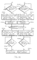
- This problem is solved by determining the time difference between the longitudinal detection and the actual start of the braking program. The braking program is then delayed by a corresponding amount of time taking this error into account. The process is explained in more detail with reference to the flowchart in FIG. 11.
- the switching and control unit 210 starts a high-frequency timer for determining the period between the longitudinal detection and the start of the next stepping motor drive step, which begins with the start of the Braking program coincides (steps S212a, S212b).
- the time delay step (S211a, S211b) is carried out independently for each stepper motor M 1 , M 2 .
- the duration of the delay time is then converted into an integer number of encoder pulses (steps S215a, S215b).
- the number Y 1 , Y 2 of the encoder pulses is determined independently for each of the stepper motors M 1 , M 2 .
- the corresponding number Y 1 , Y 2 of the correcting encoder pulses is then added to the delay counter for each stepper motor in steps S216a, S216b, so that the start of the acceleration program (steps S218a, S218b) is delayed by further Y 1 or Y 2 encoder pulses.
- the time period between the successive stepper motor pulses 216 can be, for example, 253 microseconds. This corresponds to five successive encoder pulses.
- each encoder pulse corresponds to a fifth of a stepper motor pulse duration or approximately 50 ⁇ s.
- the invention has particular reference to electrophotographic devices and Method has been described, the invention is not limited thereto, but is applicable to other areas in which a precise alignment of one moving path with an image-bearing element.
Landscapes
- Physics & Mathematics (AREA)
- General Physics & Mathematics (AREA)
- Registering Or Overturning Sheets (AREA)
- Control Or Security For Electrophotography (AREA)
- Handling Of Sheets (AREA)
- Handling Of Continuous Sheets Of Paper (AREA)
- Inking, Control Or Cleaning Of Printing Machines (AREA)
- Controlling Sheets Or Webs (AREA)
Abstract
Description
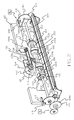
- Fig. 1
- eine Seitenansicht eines Bogenregistersystems, teilweise in Schnittdarstellung, wobei Teile zur besseren Übersicht entfernt sind;
- Fig. 2
- eine perspektivische Ansicht des Bogenregistersystems aus Fig. 1, wobei Teile zur besseren Übersicht entfernt oder nicht vollständig dargestellt sind;
- Fig. 3
- eine Draufsicht des Bogenregistersystems aus Fig. 1, wobei Teile zur besseren Übersicht entfernt oder nicht vollständig dargestellt sind;
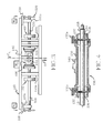
- Fig. 4
- eine Frontalansicht in Schnittdarstellung der dritten Walzenanordnung des Bogenregistersystems aus Fig. 1;
- Fig. 5
- eine schematische Darstellung des Bogentransportwegs zur Darstellung der Maßnahmen, mit denen ein einzelner Bogen bei seinem Transport entlang eines Transportwegs von dem Bogenregistersystem aus Fig. 1 beaufschlagt wird;
- Fig. 6
- eine grafische Darstellung des Profils der Umfangsgeschwindigkeit im zeitlichen Verlauf für die Antriebswalzen des Bogenregistersystems aus Fig. 1;
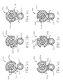
- Fig. 7a-7f
- entsprechende Seitenansichten der Antriebswalzen des Bogenregistersystem aus Fig. 1 zu verschiedenen Zeitintervallen im Betrieb des Bogenregistersystems;
- Fig. 8
- eine schematische Darstellung einer Schaltung zur Steuerung eines oder mehrerer Schrittmotoren gemäß einem Ausführungsbeispiel der Erfindung;
- Fig. 9
- eine schematische Darstellung einer zweiten Schaltung zur Steuerung von Schrittmotoren gemäß einem zweiten Ausführungsbeispiel der Erfindung;
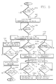
- Fig. 10
- ein Ablaufdiagramm zur Beschreibung des Betriebs der Schaltung aus Fig. 9; und
- Fig. 11
- ein Ablaufdiagramm zur weiteren Beschreibung des Betriebs der Schaltung aus Fig. 9.
| Verzögerungszeit | Y-Wert |
| 0-50 µs | 1 Codiererimpuls |
| 51-100 µs | 2 Codiererimpulse |
| 101-150 µs | 3 Codiererimpulse |
| 151-200 µs | 4 Codiererimpulse |
| 201-253 µs | 5 Codiererimpulse |
- 10
- Schräglaufregistervorrichtung
- 100
- Bogenregistersystem
- 102
- erste Antriebsbaugruppe
- 104
- zweite Antriebsbaugruppe
- 106
- dritte Antriebsbaugruppe
- 108
- erste Welle
- 110
- Rahmen
- 110a
- Lager
- 110b
- Lager
- 110c
- Lager
- 110d
- Lager
- 112
- erste Antriebswalze
- 112a
- Umfangssegment
- 112b
- Abstandswalzenlager
- 114
- Getriebezug
- 114a
- Rad
- 116
- Markierung
- 118
- Sensormechanismus
- 118a,b
- Schrittmotoransteuerungsleitungen
- 120
- zweite Welle
- 122
- zweite Antriebswalze
- 122a
- Umfangssegment
- 122b
- Abstandswalzenlager
- 124
- Getriebezug
- 124a
- Rad
- 126
- Erkennungszeichen
- 128
- Sensormechanismus
- 130
- Rohr
- 132
- dritte Antriebswalze
- 132a
- gebogenes Umfangssegment
- 134
- Stift
- 136
- Nut
- 138
- Riemenscheiben-/Riemengruppe
- 138a
- Riemenscheibe
- 138b
- Riemenscheibe
- 138c
- Antriebsriemen
- 140
- Halterung
- 142
- Antriebswelle
- 144
- Rad
- 146
- Platte
- 148
- Erkennungszeichen
- 150
- Sensormechanismus
- 152
- Welle
- 154
- Mitläuferwalzen
- 156
- Mitläuferwalzen
- 160a
- Spaltsensor
- 160b
- Spaltsensor
- 162a
- Spurlängssensor
- 162b
- Spurlängssensor
- 164
- Sensor
- 200
- Codierrad
- 202
- Lichtquelle
- 204
- Fotomesswandler
- 206
- Codiererimpulse
- 208
- Leitung
- 210
- Schalt- und Steuereinheit
- 212
- Leitung
- 214
- Impulsgenerator
- 216
- Schrittmotorimpulse
- 216a, 216b
- Schrittmotor-Ansteuerungsimpulse
- 218
- Leitung
- 220
- Registersystemsteuerung
- 302
- programmierbarer Zeitgeber
- CTR1
- Zähler 1
- CTR2
- Zähler 2
- I
- Bild
- M1
- erster Schrittmotor
- M2
- zweiter Schrittmotor
- M3
- dritter Schrittmotor
- Out 1
- Ausgabeleitung
- Out 2
- Ausgabeleitung
- P
- Bogentransportweg
- R
- Übertragungswalze
- REG1
- Register 1
- REG2
- Register 2
- S
- Bogen
- T
- Übertragungsstation
- W
- Bahn
- Z
- Zeitpunkt
Claims (11)
- Vorrichtung zum Vorwärtsbewegen eines Empfangselements in einer passgenau ausgerichteten Beziehung mit einem bildtragenden Element, das sich mit einer Bildtransportgeschwindigkeit bewegt, wobei die Vorrichtung folgendes umfasst:einen Motor (M1), der auf Motoransteuerungsimpulse (216a,b) anspricht;ein Antriebselement (102), das zum Eingriff mit dem Empfangselement betreibbar ist;eine Antriebskupplung (108, 114), die den Motor und das Antriebselement (102) miteinander verbindet; undeinen Codierer (200), der zum Erzeugen von Codiererimpulsen (206) betreibbar ist, die der Bewegung des bildtragenden Elements entsprechen; undeinen Impulsgenerator, der zum Erzeugen von Motoransteuerungsimpulsen betreibbar ist, wobei der Impulsgenerator mit dem Motor (M1) verbunden ist und Motoransteuerungsimpulse in Ansprechen auf die Codiererimpulse (206) zum Beschleunigen des Empfangselements auf eine Geschwindigkeit erzeugt, die ungefähr gleich der Bildtransportgeschwindigkeit (220) ist.
- Vorrichtung nach Anspruch 1,
dadurch gekennzeichnet, dass die Vorrichtung, die weiterhin einen Zeitgeber (302) umfasst, der zum Bestimmen einer Zeitverzögerung zwischen der Erfassung des Empfangselements durch einen Spurlängssensor (162a/b) und dem Beginn einer nachfolgenden Bewegung des Motors (M1) betreibbar ist sowie
eine Verzögerungseinrichtung, die zur Verzögerung der Beschleunigung des Empfangselements auf die ungefähre Bildtransportgeschwindigkeit (220) um den Betrag der Verzögerungszeit betreibbar ist. - Vorrichtung nach einem der Ansprüche 1 bis 2,
dadurch gekennzeichnet, dass der Motor (M1) ein Schrittmotor ist, der zum Antreiben des Antriebselements (102) in einer Vielzahl von Schritten konfiguriert ist. - Vorrichtung nach einem der Ansprüche 1 bis 3,
dadurch gekennzeichnet, dass das Empfangselement ein zugeschnittener Bogen Papier oder eines transparenten Materials ist. - Empfangselement-Registersystem zum passgenauen Ausrichten eines Empfangselements auf einem im Wesentlichen ebenen Transportweg (P) relativ zu einem bildtragenden Element, das sich mit einer Bildtransportgeschwindigkeit (220) bewegt, wobei das Empfangselement-Registersystem folgendes umfasst:einen Codierer (200), der zur Verfolgung der Bewegung des bildtragenden Elements betreibbar ist;eine um eine Achse drehbare Antriebsbaugruppe (102, 104, 106);einen Motor (M1), der zum Antreiben der Antriebsbaugruppe (102, 104, 106) derart betreibbar ist, dass das Empfangselement auf dem Transportweg (P) vorwärts bewegbar ist, und dass der Motor (M1) gemäß einer Ausgabe des Codierers (200) ansteuerbar ist, um das Empfangselement auf eine Geschwindigkeit zu bringen, die im Wesentlichen gleich der Bildtransportgeschwindigkeit (220) ist.
- Empfangselement-Registersystem zum passgenauen Ausrichten eines Empfangselements auf einem im Wesentlichen ebenen Transportweg (P) relativ zu einem bildtragenden Element, das sich mit einer Bildtransportgeschwindigkeit (220) bewegt, wobei das Empfangselement-Registersystem folgendes umfasst:einen Codierer (200), der zur Verfolgung der Bewegung des bildtragenden Elements betreibbar ist;eine um eine Achse drehbare Antriebsbaugruppe (102, 104, 106);einen Motor (M1), der zum Antreiben der Antriebsbaugruppe (102, 104, 106) derart betreibbar ist, dass das Empfangselement auf dem Transportweg (P) vorwärts bewegbar ist, undeinen Mikroprozessor, der zum Empfangen eines Eingangssignals (206) von dem Codierer (200) und zum Ansteuern des Motors (M1) gemäß des Codierer-Eingangssignals betreibbar ist, um die Bewegung des Empfangselements auf eine Geschwindigkeit zu beschleunigen, die im Wesentlichen gleich der Bildtransportgeschwindigkeit (220) ist.
- Empfangselement-Registersystem nach Anspruch 6,
dadurch gekennzeichnet, dass das Empfangselement-Registersystem zudem einen Sensor (160a,b) umfasst, der zum Erfassen einer Vorderkante des Empfangselements betreibbar ist, wenn diese das Empfangselement-Registersystem erreicht wobei
der Mikroprozessor (210) betreibbar ist, um ein Sensor-Eingangssignal von dem Sensor (160a,b) zu empfangen, eine Zeit zwischen der Erfassung der Vorderkante des Empfangselements und einer nachfolgenden Bewegung des Motors (M1) auf Basis des Sensor-Eingangssignals zu bestimmen und die Ansteuerung des Motors (M1) um die ermittelte Zeitdauer zu verzögern. - Empfangselement-Registersystem zum passgenauen Ausrichten eines Empfangselements auf einem im Wesentlichen ebenen Transportweg (P) relativ zu einem bildtragenden Element, das sich mit einer Bildtransportgeschwindigkeit (220) bewegt, wobei das Empfangselement-Registersystem folgendes umfasst:einen Codierer (200), der zur Verfolgung der Bewegung des bildtragenden Elements betreibbar ist;eine um eine Achse drehbare Antriebsbaugruppe (102, 104, 106);einen Motor (M1), der zum Antreiben der Antriebsbaugruppe (102, 104, 108) derart betreibbar ist, dass das Empfangselement auf dem Transportweg (P) vorwärts bewegbar ist, underste Mittel zum Ansteuern des Motors (M1) in Ansprechen auf eine Ausgabe des Codierers (200), um die Bewegung des Empfangselement auf eine Geschwindigkeit zu beschleunigen, die im Wesentlichen gleich der Bildtransportgeschwindigkeit (220) ist.
- Empfangselement-Registersystem nach Anspruch 8,
dadurch gekennzeichnet, dass das Empfangselement-Registersystem zudem einen Sensor (160a,b) umfasst, der zum Erfassen einer Vorderkante des Empfangselements betreibbar ist, wenn diese das Empfangselement-Registersystem erreicht, sowieeinen Zeitgeber (302), der zum Empfangen eines Eingabesignal von dem Sensor (160a,b) und zum Bestimmen der Zeitdauer zwischen der Erfassung der Vorderkante des Empfangselements und einer nachfolgenden Bewegung des Motors (M1) betreibbar ist; undzweite Mittel zum Verzögern der Ansteuerung der Antriebsbaugruppe (102, 104, 106) durch die ersten Mittel um die ermittelte Zeitdauer. - Verfahren zum Bewegen eines Empfangselements in passgenaue Ausrichtung mit einem bildtragenden Element, das sich mit einer Bildtransportgeschwindigkeit (220) bewegt, wobei das Verfahren folgende Schritte umfasst:Bereitstellen eines Codierers (200), der die Bewegung des bildtragenden Elements verfolgt;Bereitstellen eines Motors (M1); undAnsteuern des Motors (M1) in Ansprechen auf eine Ausgabe des Codierers (200), um das Empfangselement auf eine Geschwindigkeit zu beschleunigen, die im Wesentlichen gleich der Bildtransportgeschwindigkeit (220) ist.
- Verfahren nach Anspruch 10, das zudem folgende Schritte umfasst:Erfassen einer Vorderkante des Empfangselements;Bestimmen einer Zeitdauer zwischen der Erfassung der Vorderkante eines Empfangselements und einer nachfolgenden Bewegung des Motors (M1); undVerzögern des Schrittes zur Ansteuerung des Motors (M1) um die ermittelte Zeitdauer.
Applications Claiming Priority (2)
| Application Number | Priority Date | Filing Date | Title |
|---|---|---|---|
| US09/698,512 US6641134B1 (en) | 2000-10-27 | 2000-10-27 | System and method for improved registration performance |
| US698512 | 2000-10-27 |
Publications (3)
| Publication Number | Publication Date |
|---|---|
| EP1211568A2 true EP1211568A2 (de) | 2002-06-05 |
| EP1211568A3 EP1211568A3 (de) | 2002-06-26 |
| EP1211568B1 EP1211568B1 (de) | 2005-09-07 |
Family
ID=24805577
Family Applications (1)
| Application Number | Title | Priority Date | Filing Date |
|---|---|---|---|
| EP01124278A Expired - Lifetime EP1211568B1 (de) | 2000-10-27 | 2001-10-18 | Vorrichtung und Verfahren zur passgenauen Ausrichtung von bildaufnehmenden Bögen, wobei die Ansteuerungsimpulse eines Schrittmotors zeitlich höher aufgelöst sind als die Codiererimpulse, die die Bewegung des Elements mit dem zu übertragenden Bildes detektieren |
Country Status (5)
| Country | Link |
|---|---|
| US (1) | US6641134B1 (de) |
| EP (1) | EP1211568B1 (de) |
| JP (1) | JP3949929B2 (de) |
| CA (1) | CA2359016A1 (de) |
| DE (2) | DE50107351D1 (de) |
Families Citing this family (41)
| Publication number | Priority date | Publication date | Assignee | Title |
|---|---|---|---|---|
| US6951335B2 (en) * | 2002-10-29 | 2005-10-04 | Hewlett-Packard Development Company, L.P. | Reciprocating linear encoder |
| US7662745B2 (en) | 2003-12-18 | 2010-02-16 | Kimberly-Clark Corporation | Stretchable absorbent composites having high permeability |
| US7174123B1 (en) * | 2003-12-19 | 2007-02-06 | Cartridge Corporation Of America, Inc. | Rigid agitator and shaft assembly |
| US7343108B2 (en) * | 2004-05-05 | 2008-03-11 | Eastman Kodak Company | Apparatus and process for altering timing in an electrographic printer |
| US7243917B2 (en) * | 2004-05-27 | 2007-07-17 | Xerox Corporation | Print media registration using active tracking of idler rotation |
| US7772456B2 (en) | 2004-06-30 | 2010-08-10 | Kimberly-Clark Worldwide, Inc. | Stretchable absorbent composite with low superaborbent shake-out |
| US7938813B2 (en) | 2004-06-30 | 2011-05-10 | Kimberly-Clark Worldwide, Inc. | Absorbent article having shaped absorbent core formed on a substrate |
| US7247215B2 (en) | 2004-06-30 | 2007-07-24 | Kimberly-Clark Worldwide, Inc. | Method of making absorbent articles having shaped absorbent cores on a substrate |
| JP4645184B2 (ja) * | 2004-12-17 | 2011-03-09 | ブラザー工業株式会社 | 被記録媒体搬送方法及び画像記録装置 |
| US20060173432A1 (en) | 2005-02-01 | 2006-08-03 | Laumer Jason M | Absorbent articles comprising polyamine-coated superabsorbent polymers |
| US20060173431A1 (en) * | 2005-02-01 | 2006-08-03 | Laumer Jason M | Absorbent articles comprising polyamine-coated superabsorbent polymers |
| US20060173433A1 (en) | 2005-02-01 | 2006-08-03 | Laumer Jason M | Absorbent articles comprising polyamine-coated superabsorbent polymers |
| JP4440146B2 (ja) * | 2005-03-10 | 2010-03-24 | 株式会社東芝 | 画像形成装置 |
| JP4429939B2 (ja) * | 2005-03-10 | 2010-03-10 | 株式会社東芝 | 画像形成装置 |
| JP4468844B2 (ja) * | 2005-03-10 | 2010-05-26 | 株式会社東芝 | 画像形成装置、シート搬送方法 |
| JP4342461B2 (ja) * | 2005-03-10 | 2009-10-14 | 株式会社東芝 | 画像形成装置 |
| JP4401986B2 (ja) * | 2005-03-10 | 2010-01-20 | 株式会社東芝 | 画像形成装置、シート搬送方法 |
| US7871401B2 (en) * | 2005-04-29 | 2011-01-18 | Kimberly-Clark Worldwide, Inc. | Absorbent article with improved fit |
| US20060246272A1 (en) * | 2005-04-29 | 2006-11-02 | Zhang Xiaomin X | Thermoplastic foam composite |
| US7737322B2 (en) * | 2005-12-21 | 2010-06-15 | Kimberly-Clark Worldwide, Inc. | Personal care products with microchemical sensors for odor detection |
| US7595734B2 (en) | 2006-04-26 | 2009-09-29 | Kimberly-Clark Worldwide, Inc. | Wetness monitoring systems with power management |
| US7489252B2 (en) | 2006-04-26 | 2009-02-10 | Kimberly-Clark Worldwide, Inc. | Wetness monitoring systems with status notification system |
| US20080052030A1 (en) * | 2006-08-22 | 2008-02-28 | Kimberly-Clark Worldwide, Inc. | Method of predicting an incontinent event |
| US7449614B2 (en) * | 2006-08-29 | 2008-11-11 | Kimberly-Clark Worldwide, Inc. | Absorbent articles including a monitoring system powered by ambient energy |
| US7504550B2 (en) * | 2006-08-31 | 2009-03-17 | Kimberly-Clark Worldwide, Inc. | Conductive porous materials |
| US7834235B2 (en) * | 2006-08-31 | 2010-11-16 | Kimberly-Clark Worldwide, Inc. | System for interactively training a child and a caregiver to assist the child to overcome bedwetting |
| US20080054408A1 (en) * | 2006-08-31 | 2008-03-06 | Kimberly-Clark Worldwide, Inc. | Conduction through a flexible substrate in an article |
| US20080057693A1 (en) * | 2006-08-31 | 2008-03-06 | Kimberly-Clark Worldwide, Inc. | Electrical conductivity bridge in a conductive multilayer article |
| US20080058747A1 (en) * | 2006-08-31 | 2008-03-06 | Arvinder Pal Singh Kainth | Absorbent articles comprising superabsorbent polymers having superior properties |
| JP2008087916A (ja) * | 2006-10-02 | 2008-04-17 | Sharp Corp | シート搬送装置 |
| US20080082068A1 (en) * | 2006-10-02 | 2008-04-03 | Jian Qin | Absorbent articles comprising carboxyalkyl cellulose fibers having permanent and non-permanent crosslinks |
| US20080082069A1 (en) * | 2006-10-02 | 2008-04-03 | Jian Qin | Absorbent articles comprising carboxyalkyl cellulose fibers having non-permanent and temporary crosslinks |
| US7935860B2 (en) * | 2007-03-23 | 2011-05-03 | Kimberly-Clark Worldwide, Inc. | Absorbent articles comprising high permeability superabsorbent polymer compositions |
| JP5260886B2 (ja) * | 2007-04-27 | 2013-08-14 | 株式会社Pfu | シート給送装置 |
| US8383877B2 (en) * | 2007-04-28 | 2013-02-26 | Kimberly-Clark Worldwide, Inc. | Absorbent composites exhibiting stepped capacity behavior |
| US8039683B2 (en) | 2007-10-15 | 2011-10-18 | Kimberly-Clark Worldwide, Inc. | Absorbent composites having improved fluid wicking and web integrity |
| US8181957B2 (en) * | 2008-07-17 | 2012-05-22 | Kabushiki Kaisha Toshiba | Sheet conveying apparatus and sheet conveying method |
| JP2010095367A (ja) * | 2008-10-17 | 2010-04-30 | Pfu Ltd | シート給送装置及び媒体検出方法 |
| JP5209443B2 (ja) * | 2008-11-04 | 2013-06-12 | 株式会社小森コーポレーション | 処理機の駆動制御方法及び駆動制御装置 |
| JP2011242534A (ja) * | 2010-05-17 | 2011-12-01 | Hitachi Plant Technologies Ltd | 基板搬送装置と基板の傾き補正 |
| CN116261440B (zh) | 2020-08-25 | 2026-02-13 | 金伯利-克拉克环球有限公司 | 吸收结构和制造吸收结构的方法 |
Family Cites Families (12)
| Publication number | Priority date | Publication date | Assignee | Title |
|---|---|---|---|---|
| US4591969A (en) * | 1983-08-11 | 1986-05-27 | International Business Machines Corporation | Microprocessor-controlled positioning system |
| US4519700A (en) | 1983-12-28 | 1985-05-28 | International Business Machines Corporation | Electronically gated paper aligner system |
| US5094442A (en) | 1990-07-30 | 1992-03-10 | Xerox Corporation | Translating electronic registration system |
| US5278624A (en) | 1992-07-07 | 1994-01-11 | Xerox Corporation | Differential drive for sheet registration drive rolls with skew detection |
| US5322273A (en) | 1993-05-18 | 1994-06-21 | Eastman Kodak Company | Sheet registration mechanism |
| US6141525A (en) * | 1995-04-28 | 2000-10-31 | Canon Kabushiki Kaisha | Image forming apparatus having correction device for lateral misalignment |
| US5731680A (en) * | 1995-06-29 | 1998-03-24 | Eastman Kodak Company | Method and apparatus for registering a sheet with an image-bearing member |
| US5794176A (en) * | 1996-09-24 | 1998-08-11 | Xerox Corporation | Adaptive electronic registration system |
| DE19845353C2 (de) | 1998-10-02 | 2003-04-17 | Motion Ges Fuer Antriebstechni | Einrichtung zur Erfassung der Drehzahl bzw. Lineargeschwindigkeit für eine Motordrehzahl- bzw. Motorlineargeschwindigkeitsregelung |
| US6342909B1 (en) * | 1999-03-23 | 2002-01-29 | Konica Corporation | Method and apparatus for image formation while considering a position of a transfer sheet in a primary scanning direction |
| US6327458B1 (en) * | 2000-04-06 | 2001-12-04 | Lexmark International, Inc. | Method and apparatus for positioning paper in an imaging system having an intermediate transfer medium |
| US6374075B1 (en) * | 2000-04-28 | 2002-04-16 | Xerox Corporation | Printing systems and methods |
-
2000
- 2000-10-27 US US09/698,512 patent/US6641134B1/en not_active Expired - Lifetime
-
2001
- 2001-10-12 CA CA002359016A patent/CA2359016A1/en not_active Abandoned
- 2001-10-18 DE DE50107351T patent/DE50107351D1/de not_active Expired - Lifetime
- 2001-10-18 EP EP01124278A patent/EP1211568B1/de not_active Expired - Lifetime
- 2001-10-18 DE DE10151489A patent/DE10151489A1/de not_active Withdrawn
- 2001-10-25 JP JP2001328163A patent/JP3949929B2/ja not_active Expired - Fee Related
Also Published As
| Publication number | Publication date |
|---|---|
| EP1211568B1 (de) | 2005-09-07 |
| DE10151489A1 (de) | 2002-05-08 |
| US6641134B1 (en) | 2003-11-04 |
| JP2002205431A (ja) | 2002-07-23 |
| CA2359016A1 (en) | 2002-04-27 |
| EP1211568A3 (de) | 2002-06-26 |
| DE50107351D1 (de) | 2005-10-13 |
| JP3949929B2 (ja) | 2007-07-25 |
Similar Documents
| Publication | Publication Date | Title |
|---|---|---|
| EP1211568B1 (de) | Vorrichtung und Verfahren zur passgenauen Ausrichtung von bildaufnehmenden Bögen, wobei die Ansteuerungsimpulse eines Schrittmotors zeitlich höher aufgelöst sind als die Codiererimpulse, die die Bewegung des Elements mit dem zu übertragenden Bildes detektieren | |
| DE69216051T2 (de) | Gerät zur Geradrichtung und Seitenausrichtung eines Blattes | |
| DE69110005T2 (de) | Gerät und Verfahren für kombiniertes Ausrichten und Positionieren von Kopierblättern. | |
| DE60109260T2 (de) | Drucksystem | |
| DE4416564C2 (de) | Blattausrichtvorrichtung | |
| DE3685628T2 (de) | Steuerung des abstellens einer maschine. | |
| DE2425207C3 (de) | Vorrichtung zum Speichern und Abgeben von Blättern | |
| DE69004483T2 (de) | Steuerung für einen Labeldrucker. | |
| DE68913480T2 (de) | Verfahren und Gerät zur Bestimmung der Druckstellung und Drucker. | |
| DE10309236B4 (de) | Vorrichtung und Verfahren zum Drucken auf beiden Oberflächen einer Bahn | |
| DE69411236T2 (de) | Blattfaltgerät mit sanfter Klemmung im Walzenspalt | |
| DE60010027T2 (de) | Verfahren und Vorrichtung zur Querausrichtung eines Blattes mit einem auf diesem zu übertragenden Bild | |
| DE2457112C3 (de) | Blatttransportvorrichtung | |
| DE69918206T2 (de) | Dispositif d'alimentation et de traitement de feuilles | |
| DE3611965A1 (de) | Bilderzeugungsgeraet | |
| DE3626819C2 (de) | ||
| DE3419440A1 (de) | Zweiseitiges aufzeichnungsverfahren und vorrichtung zum zweiseitigen bedrucken auf der basis einer einseitigen vorlage | |
| DE4017777C2 (de) | ||
| DE3731466C2 (de) | Blatttransporteinrichtung | |
| DE2318297C3 (de) | Elektrostatisches Kopiergerät | |
| DE3041745A1 (de) | Elektrostatisches kopiergeraet | |
| EP1202124A2 (de) | Vorrichtung und Verfahren für ein vergrössertes betriebliches Zeitfenster zur passgenauen Ausrichtung von Empfangsbogen | |
| DE2806397C2 (de) | Mit variabler Vergrößerung arbeitendes elektrophotographisches Kopiergerät | |
| DE69011214T2 (de) | Bilderzeugungsgerät. | |
| EP1170237B1 (de) | Verfahren zur Ausrichtung bogenförmigen Materials |
Legal Events
| Date | Code | Title | Description |
|---|---|---|---|
| PUAI | Public reference made under article 153(3) epc to a published international application that has entered the european phase |
Free format text: ORIGINAL CODE: 0009012 |
|
| PUAL | Search report despatched |
Free format text: ORIGINAL CODE: 0009013 |
|
| AK | Designated contracting states |
Kind code of ref document: A2 Designated state(s): AT BE CH CY DE DK ES FI FR GB GR IE IT LI LU MC NL PT SE TR |
|
| AX | Request for extension of the european patent |
Free format text: AL;LT;LV;MK;RO;SI |
|
| AK | Designated contracting states |
Kind code of ref document: A3 Designated state(s): AT BE CH CY DE DK ES FI FR GB GR IE IT LI LU MC NL PT SE TR |
|
| AX | Request for extension of the european patent |
Free format text: AL;LT;LV;MK;RO;SI |
|
| 17P | Request for examination filed |
Effective date: 20020521 |
|
| AKX | Designation fees paid |
Designated state(s): AT BE CH CY DE DK ES FI FR GB GR IE IT LI LU MC NL PT SE TR |
|
| 17Q | First examination report despatched |
Effective date: 20030228 |
|
| RAP1 | Party data changed (applicant data changed or rights of an application transferred) |
Owner name: EASTMAN KODAK COMPANY |
|
| GRAP | Despatch of communication of intention to grant a patent |
Free format text: ORIGINAL CODE: EPIDOSNIGR1 |
|
| RBV | Designated contracting states (corrected) |
Designated state(s): BE CH DE FR GB IT LI NL |
|
| GRAJ | Information related to disapproval of communication of intention to grant by the applicant or resumption of examination proceedings by the epo deleted |
Free format text: ORIGINAL CODE: EPIDOSDIGR1 |
|
| GRAP | Despatch of communication of intention to grant a patent |
Free format text: ORIGINAL CODE: EPIDOSNIGR1 |
|
| GRAS | Grant fee paid |
Free format text: ORIGINAL CODE: EPIDOSNIGR3 |
|
| RBV | Designated contracting states (corrected) |
Designated state(s): DE FR GB |
|
| GRAA | (expected) grant |
Free format text: ORIGINAL CODE: 0009210 |
|
| AK | Designated contracting states |
Kind code of ref document: B1 Designated state(s): DE FR GB |
|
| REG | Reference to a national code |
Ref country code: GB Ref legal event code: FG4D Free format text: NOT ENGLISH |
|
| REF | Corresponds to: |
Ref document number: 50107351 Country of ref document: DE Date of ref document: 20051013 Kind code of ref document: P |
|
| GBT | Gb: translation of ep patent filed (gb section 77(6)(a)/1977) |
Effective date: 20051128 |
|
| ET | Fr: translation filed | ||
| PLBE | No opposition filed within time limit |
Free format text: ORIGINAL CODE: 0009261 |
|
| STAA | Information on the status of an ep patent application or granted ep patent |
Free format text: STATUS: NO OPPOSITION FILED WITHIN TIME LIMIT |
|
| 26N | No opposition filed |
Effective date: 20060608 |
|
| PGFP | Annual fee paid to national office [announced via postgrant information from national office to epo] |
Ref country code: GB Payment date: 20120925 Year of fee payment: 12 |
|
| PGFP | Annual fee paid to national office [announced via postgrant information from national office to epo] |
Ref country code: FR Payment date: 20121010 Year of fee payment: 12 Ref country code: DE Payment date: 20121031 Year of fee payment: 12 |
|
| GBPC | Gb: european patent ceased through non-payment of renewal fee |
Effective date: 20131018 |
|
| PG25 | Lapsed in a contracting state [announced via postgrant information from national office to epo] |
Ref country code: GB Free format text: LAPSE BECAUSE OF NON-PAYMENT OF DUE FEES Effective date: 20131018 |
|
| REG | Reference to a national code |
Ref country code: DE Ref legal event code: R119 Ref document number: 50107351 Country of ref document: DE Effective date: 20140501 |
|
| REG | Reference to a national code |
Ref country code: FR Ref legal event code: ST Effective date: 20140630 |
|
| PG25 | Lapsed in a contracting state [announced via postgrant information from national office to epo] |
Ref country code: FR Free format text: LAPSE BECAUSE OF NON-PAYMENT OF DUE FEES Effective date: 20131031 Ref country code: DE Free format text: LAPSE BECAUSE OF NON-PAYMENT OF DUE FEES Effective date: 20140501 |