EP1211206B1 - Vorrichtung und Verfahren zum Messen der Bahnspannung - Google Patents
Vorrichtung und Verfahren zum Messen der Bahnspannung Download PDFInfo
- Publication number
- EP1211206B1 EP1211206B1 EP01126547A EP01126547A EP1211206B1 EP 1211206 B1 EP1211206 B1 EP 1211206B1 EP 01126547 A EP01126547 A EP 01126547A EP 01126547 A EP01126547 A EP 01126547A EP 1211206 B1 EP1211206 B1 EP 1211206B1
- Authority
- EP
- European Patent Office
- Prior art keywords
- roller
- measuring
- web
- web tension
- drive
- Prior art date
- Legal status (The legal status is an assumption and is not a legal conclusion. Google has not performed a legal analysis and makes no representation as to the accuracy of the status listed.)
- Expired - Lifetime
Links
Images
Classifications
-
- G—PHYSICS
- G01—MEASURING; TESTING
- G01L—MEASURING FORCE, STRESS, TORQUE, WORK, MECHANICAL POWER, MECHANICAL EFFICIENCY, OR FLUID PRESSURE
- G01L5/00—Apparatus for, or methods of, measuring force, work, mechanical power, or torque, specially adapted for specific purposes
- G01L5/04—Apparatus for, or methods of, measuring force, work, mechanical power, or torque, specially adapted for specific purposes for measuring tension in flexible members, e.g. ropes, cables, wires, threads, belts or bands
- G01L5/10—Apparatus for, or methods of, measuring force, work, mechanical power, or torque, specially adapted for specific purposes for measuring tension in flexible members, e.g. ropes, cables, wires, threads, belts or bands using electrical means
- G01L5/108—Apparatus for, or methods of, measuring force, work, mechanical power, or torque, specially adapted for specific purposes for measuring tension in flexible members, e.g. ropes, cables, wires, threads, belts or bands using electrical means for measuring a reaction force applied on a single support, e.g. a glider
-
- B—PERFORMING OPERATIONS; TRANSPORTING
- B65—CONVEYING; PACKING; STORING; HANDLING THIN OR FILAMENTARY MATERIAL
- B65H—HANDLING THIN OR FILAMENTARY MATERIAL, e.g. SHEETS, WEBS, CABLES
- B65H23/00—Registering, tensioning, smoothing or guiding webs
- B65H23/04—Registering, tensioning, smoothing or guiding webs longitudinally
- B65H23/044—Sensing web tension
-
- G—PHYSICS
- G01—MEASURING; TESTING
- G01L—MEASURING FORCE, STRESS, TORQUE, WORK, MECHANICAL POWER, MECHANICAL EFFICIENCY, OR FLUID PRESSURE
- G01L5/00—Apparatus for, or methods of, measuring force, work, mechanical power, or torque, specially adapted for specific purposes
- G01L5/04—Apparatus for, or methods of, measuring force, work, mechanical power, or torque, specially adapted for specific purposes for measuring tension in flexible members, e.g. ropes, cables, wires, threads, belts or bands
- G01L5/10—Apparatus for, or methods of, measuring force, work, mechanical power, or torque, specially adapted for specific purposes for measuring tension in flexible members, e.g. ropes, cables, wires, threads, belts or bands using electrical means
-
- B—PERFORMING OPERATIONS; TRANSPORTING
- B21—MECHANICAL METAL-WORKING WITHOUT ESSENTIALLY REMOVING MATERIAL; PUNCHING METAL
- B21B—ROLLING OF METAL
- B21B38/00—Methods or devices for measuring, detecting or monitoring specially adapted for metal-rolling mills, e.g. position detection, inspection of the product
- B21B38/06—Methods or devices for measuring, detecting or monitoring specially adapted for metal-rolling mills, e.g. position detection, inspection of the product for measuring tension or compression
Definitions
- the present invention relates to a device and a method for measuring or controlling a web tension according to the preambles of claims 1 and 10.
- Such a device and such a method are e.g. from JP 01 321263 known.
- Web-fed rotary printing machines print on a continuous web, e.g. made of paper.
- the continuous web is printed with an image, then the web is folded and cut into signatures.
- the process of printing the web with an image as well as folding the web creates tension in the web. The correct tension should be maintained during the printing and folding process in the web.
- a method of measuring the correct voltage uses a voltage transfer device.
- the existing voltage transfer devices are analog devices that require frequent calibration and can be easily damaged when overloaded.
- the bandwidth of existing voltage transfer devices is insufficient for some applications.
- the existing tension transmitting devices consist of tension measuring assemblies mounted in the ends of the tensioning rollers. The arrangements make some applications, e.g. Measuring a web tension on a driven roller or a liquid-cooled roller, difficult, expensive or even impossible.
- An additional and alternative object of the invention is to provide a simpler apparatus for generating web tension information from the rolls.
- Yet another or alternative object of the present invention is to provide a device which can serve not only as a compensator but also as a tension measuring device in a path measuring range
- the present invention provides an apparatus for measuring web tension with a roller for contacting the web of material, the roller having an axis of rotation which is movable by the web in a first direction, a drive connected to the roller, the drive being used to urge the axis of the roller in a second direction against the first direction, and a controller connected to the counteracting drive for measuring the web tension.
- the web tension information can advantageously be determined easily and efficiently.
- the control of the present invention allows to serve both as a belt compensator and as a web tension measuring device in a given path measuring range.
- the movable roller may be a liquid-cooled roller.
- the liquid-cooled roll advantageously improves the performance of printing the web.
- the counteracting drive is a motor.
- the motor provides the advantage that the present invention can be operated at higher voltages without causing more damage or jamming.
- the controller is preferably an electronic circuit.
- the use of electronic circuitry eliminates the need for frequent calibration of the present invention.
- the web tension measuring device may comprise a plurality of lever arms, a pivot axis, a plurality of pulleys, a belt, an axis of the drive, and / or an axis of rotation, each device being mechanically connected to the counteracting drive.
- the roller may remain stationary in the method of measuring tension in the web. This fact advantageously makes it easier to obtain information about the web tension.
- the roller may be rotatable about a pivot axis in a lever or lever arm, wherein a path compensator algorithm determines the desired position of the roller.
- the rotation about the pivot axis provides the advantage that the roller can perform the voltage measuring function and the function as a web or belt compensator.
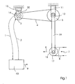
- Fig. 1 shows a schematic view of the web tension measuring device with a web 8 which is moved by a roller 17.
- the roller 17 has an axis or axis of rotation 18 on.
- the operation of the ducking machine causes the tension in the web 8 to exert a displacement force in a first direction 7 on the movable roller 17.
- the roll axis 18 of the movable roll 17, which may be a liquid-cooled or a driven roll, is therefore urged in the direction 7.
- the roller shaft 18 in turn exerts a force on a first lever arm 19 and a second lever arm 16 (see Fig. 2), both of which are fixedly connected to a pivot axis 12.
- the first and second lever arms 19, 16 thus provide torque in the pivot axis 12.
- the first pulley 5 transmits the torque by means of a belt 4 to a second pulley 3, the belt 4 preferably having a toothed inner surface.
- the rotation of the second pulley 3 transmits the torque to the same through a fixed connection with the rotational axis 14 of the counteracting drive.
- the axis of rotation 14 of the counteracting drive is connected to the drive 15, for example a motor, and thus transmits the torque to the drive 15.
- the controller 10 outputs a zero position signal to the drive 15 so that the drive 15 counteracts the torque exerted by the axis 14 of the drive, wherein the torque 20 of the drive counteracts the torque emanating from the axis 14 of the drive ,
- the torque 20 of the drive stabilizes the axis 14 of the drive.
- the axis 14 of the drive in turn prevents the rotation of the second pulley 3, which prevents the rotation of the first pulley 5 by means of the belt 4.
- the first pulley 5 prevents rotation of the pivot axis 12, and the pivot axis 12 in turn stabilizes the first and second lever arms 19, 16.
- the first and second lever arms 19, 16 stabilize the movable roller 17 so that the axle 18 remains stationary.
- the movable roller 17 exerts a second deflection force in a second direction 6, which acts the same and counter to the first deflection force, which starts from the tension in the web 8.
- the controller 10 which may be an electronic circuit or a microprocessor, reads a value representing the torque 20 to the motor 15 or axle 14 through a first connection 1. The controller then sends a zero command to the drive 15 via a second link 2, e.g. a motor that causes the drive 15 to maintain the null position so that the axle 14 does not rotate. The controller 10 then converts the value sent via the link 1, which represents the torque 20 of the drive, to a measurement of the web tension in dependence on the length of the first and second lever arms 19, 16, the diameter of the movable roller 17 and the ratio of first pulley 5 to the second pulley 3. The controller 10 outputs the measurement of the web tension as a digital signal 9.
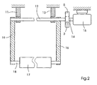
- FIG. 2 shows a schematic front view of the web tension measuring device showing the drive 15 and the second lever arm 16.
- the movable roller 17 is fixedly attached to the rotation axis 18, and the rotation axis 18 is fixed to the first and second lever arms 19, 16 and can rotate therein.
- the pivot axis 12 is shown, which is fixedly connected to the first and second lever arm 19, 16 and attached to the first and second fastening element 11, 13.
- the pivot axis 12, which rotates freely in the first and second fastening elements 11, 13, is fixedly connected to the first pulley 5.
- the belt 4 provides a connection between the first pulley 5 and the second pulley 3 (see Fig. 1).
- the second pulley 3 is fixedly connected to the axle 14 of the drive, which is connected to the drive 15.
- the controller 10 may send a position command to the drive 15 via the first link 1.
- the position command which is based on a desired change in the position of the movable roller 17, as determined in a normal compensation calculation, leads to a change in the torque 20 of the drive 15, so that the change of the torque, the first and second lever arm 19, 16 causes to rotate about the pivot axis 12 and thus the movable roller 17 allows to move.
- the drive 15 then adjusts the torque 20 of the drive by subtracting the torque required to accelerate the mechanical parts of the present invention from the torque 20 of the drive, thus recovering the torque 20 of the drive equal to the torque caused by the web tension sets.
- the device may thus serve as a web tension compensator.
- the drive 15 is preferably an electric motor with a shaft.
Landscapes
- Physics & Mathematics (AREA)
- General Physics & Mathematics (AREA)
- Controlling Rewinding, Feeding, Winding, Or Abnormalities Of Webs (AREA)
- Inking, Control Or Cleaning Of Printing Machines (AREA)
- Force Measurement Appropriate To Specific Purposes (AREA)
- Devices For Conveying Motion By Means Of Endless Flexible Members (AREA)
Applications Claiming Priority (2)
| Application Number | Priority Date | Filing Date | Title |
|---|---|---|---|
| US09/726,240 US6752013B2 (en) | 2000-11-29 | 2000-11-29 | Device and method for web tension measurement |
| US726240 | 2000-11-29 |
Publications (3)
| Publication Number | Publication Date |
|---|---|
| EP1211206A2 EP1211206A2 (de) | 2002-06-05 |
| EP1211206A3 EP1211206A3 (de) | 2003-10-15 |
| EP1211206B1 true EP1211206B1 (de) | 2006-06-21 |
Family
ID=24917760
Family Applications (1)
| Application Number | Title | Priority Date | Filing Date |
|---|---|---|---|
| EP01126547A Expired - Lifetime EP1211206B1 (de) | 2000-11-29 | 2001-11-15 | Vorrichtung und Verfahren zum Messen der Bahnspannung |
Country Status (5)
| Country | Link |
|---|---|
| US (1) | US6752013B2 (enExample) |
| EP (1) | EP1211206B1 (enExample) |
| JP (1) | JP4488154B2 (enExample) |
| AT (1) | ATE330891T1 (enExample) |
| DE (2) | DE10156206A1 (enExample) |
Families Citing this family (11)
| Publication number | Priority date | Publication date | Assignee | Title |
|---|---|---|---|---|
| US6993964B2 (en) * | 2004-02-04 | 2006-02-07 | The Procter & Gamble Company | Method of determining a modulus of elasticity of a moving web material |
| DE102007015785A1 (de) * | 2007-03-30 | 2008-10-02 | Man Roland Druckmaschinen Ag | Verfahren und Vorrichtung zur Ermittlung der Bahnspannung bzw. des Bahnzugs in einer Bedruckstoffbahn |
| US8733685B2 (en) | 2010-10-25 | 2014-05-27 | The Procter & Gamble Company | Apparatus for reducing web feed rate variations induced by parent roll geometry variations |
| US8740130B2 (en) | 2010-10-25 | 2014-06-03 | The Procter & Gamble Company | Alternative method for reducing web feed rate variations induced by parent roll geometry variations |
| US9434573B2 (en) | 2010-10-25 | 2016-09-06 | The Procter & Gamble Company | Alternative method for reducing web feed rate variations induced by parent roll geometry variations |
| US8733686B2 (en) | 2010-10-25 | 2014-05-27 | The Procter & Gamble Company | Alternative apparatus for reducing web feed rate variations induced by parent roll geometry variations |
| US8733687B2 (en) | 2010-10-25 | 2014-05-27 | The Procter & Gamble Company | Alternative apparatus for reducing web feed rate variations induced by parent roll geometry variations |
| US8757535B2 (en) | 2010-10-25 | 2014-06-24 | The Procter & Gamble Company | Method for reducing web feed rate variations induced by parent roll geometry variations |
| US9434572B2 (en) | 2010-10-25 | 2016-09-06 | The Procter & Gamble Company | Alternative method for reducing web feed rate variations induced by parent roll geometry variations |
| US9816906B2 (en) | 2014-04-25 | 2017-11-14 | Honeywell International Inc. | Apparatus and method for stretch measurements of tissue webs |
| DE102020134370A1 (de) | 2020-12-21 | 2022-06-23 | Inficon Gmbh | Gaslecksuchvorrichtung und Gaslecksuchverfahren zur Erkennung eines Gaslecks in einem Prüfling |
Family Cites Families (26)
| Publication number | Priority date | Publication date | Assignee | Title |
|---|---|---|---|---|
| GB995874A (en) | 1961-04-25 | 1965-06-23 | Asea Ab | Means for regulating the tension in webs, bands, sheets, tracks or the like |
| GB1048175A (en) | 1965-07-09 | 1966-11-16 | Plamag Plauener Druckmaschinen | Paper web tension governor |
| DE1774714A1 (de) | 1968-08-21 | 1971-10-21 | Allmaenna Svenska Elek Ska Ab | Anordnung zum Umspulen von bandfoermigem Gut |
| DE2127993C2 (de) | 1971-06-05 | 1982-08-26 | Gebrüder Sucker, 4050 Mönchengladbach | Vorrichtung zur Regelung der Wickelspannung bahnförmig geführten Gutes |
| US3777959A (en) | 1972-02-25 | 1973-12-11 | Du Pont | Apparatus for monitoring and controlling tension in an advancing flexible elongate material |
| CH574363A5 (enExample) | 1973-11-13 | 1976-04-15 | Bobst Fils Sa J | |
| DE2510451C3 (de) * | 1975-03-11 | 1984-04-26 | Agfa-Gevaert Ag, 5090 Leverkusen | Vorrichtung zum mechanischen Abtasten von lokalen Verdickungen in Papier- und Folienbahnen |
| US4144700A (en) * | 1976-12-14 | 1979-03-20 | Murata Kikai Kabushiki Kaisha | False twisting apparatus |
| US4159808A (en) | 1978-01-06 | 1979-07-03 | Butler Automatic, Inc. | Variable ratio winder |
| IT1119102B (it) | 1979-06-07 | 1986-03-03 | Cerutti Spa Off Mec | Dispositivo elettronico di regolazione e controllo per il comando di rulli di traino di macchine rotative rotocalco |
| IT1173847B (it) | 1984-03-15 | 1987-06-24 | Ansaldo Sistemi Ind Spa | Dispositivo regolatore del tipo del nastro in laminazione a caldo |
| DE3443357C1 (de) * | 1984-11-28 | 1986-04-17 | Vits-Maschinenbau Gmbh, 4018 Langenfeld | Bahnspannungsregeleinrichtung an einem Vertikaltrockner fuer Warenbahnen |
| JPS61146827A (ja) * | 1984-12-17 | 1986-07-04 | Murata Mach Ltd | 糸継装置の自動検査装置 |
| JPH01321263A (ja) | 1988-06-22 | 1989-12-27 | Hitachi Ltd | 張力制御方法 |
| DE3940744C2 (de) | 1989-12-09 | 1994-03-17 | Hansmann Erich Dipl Ing | Walze für eine Vorrichtung zum Bearbeiten von bahn- oder tafelförmigem Material |
| DE4003659A1 (de) | 1990-02-07 | 1991-08-08 | Kokes Michael Dipl Ing Fh | Vorrichtung und verfahren zur konstanten dehnungsregelung fuer durchlaufende bahnen |
| DE4019108C2 (de) | 1990-06-15 | 1994-08-18 | Stahlkontor Maschinenbau | Vorrichtung zur Regelung bzw. Konstanthaltung der frei wählbaren und geschwindigkeitsunabhängigen Zugkraft von bahn- oder fadenartigem Wickelgut aus Kunststoff, Papier, Textil, Metallen oder dergleichen |
| DE4027938A1 (de) | 1990-09-04 | 1992-03-05 | Minnesota Mining & Mfg | Vorrichtung zum vorbewegen von aufzeichnungsmaterial in einer druckervorrichtung |
| US6001199A (en) * | 1990-10-24 | 1999-12-14 | Hunter Douglas Inc. | Method for manufacturing a fabric light control window covering |
| DE4039108C1 (enExample) * | 1990-12-07 | 1992-04-16 | Man Roland Druckmaschinen Ag, 6050 Offenbach, De | |
| US5472127A (en) * | 1992-07-21 | 1995-12-05 | Kawasaki Steel Corporation | Strip tension control apparatus |
| DE4232635C2 (de) | 1992-09-29 | 1996-12-05 | Siemens Matsushita Components | Verfahren und Vorrichtung zur Regelung des Folienzuges bei der Herstellung elektrischer Wickelkondensatoren |
| DE9315076U1 (de) | 1993-01-22 | 1994-02-03 | Sulzer-Escher Wyss Gmbh, 88212 Ravensburg | Vorrichtung zur Ermittlung der Materialbahnspannung |
| EP0652104B1 (de) * | 1993-11-05 | 2002-04-10 | MAN Roland Druckmaschinen AG | Druckwerk für wasserlosen Offsetdruck |
| JP2819283B2 (ja) | 1996-12-24 | 1998-10-30 | 株式会社東京機械製作所 | 連続紙走行張力制御装置 |
| FR2761673B1 (fr) | 1997-04-02 | 1999-06-18 | Soc Et De Machines Pour Les Ar | Dispositif de controle automatique de la tension d'une bande de materiaux dans une machine a imprimer |
-
2000
- 2000-11-29 US US09/726,240 patent/US6752013B2/en not_active Expired - Fee Related
-
2001
- 2001-11-15 AT AT01126547T patent/ATE330891T1/de not_active IP Right Cessation
- 2001-11-15 DE DE10156206A patent/DE10156206A1/de not_active Withdrawn
- 2001-11-15 EP EP01126547A patent/EP1211206B1/de not_active Expired - Lifetime
- 2001-11-15 DE DE50110232T patent/DE50110232D1/de not_active Expired - Lifetime
- 2001-11-29 JP JP2001364925A patent/JP4488154B2/ja not_active Expired - Fee Related
Also Published As
| Publication number | Publication date |
|---|---|
| ATE330891T1 (de) | 2006-07-15 |
| EP1211206A2 (de) | 2002-06-05 |
| US6752013B2 (en) | 2004-06-22 |
| JP4488154B2 (ja) | 2010-06-23 |
| DE50110232D1 (de) | 2006-08-03 |
| EP1211206A3 (de) | 2003-10-15 |
| US20020062689A1 (en) | 2002-05-30 |
| DE10156206A1 (de) | 2002-06-13 |
| JP2002234650A (ja) | 2002-08-23 |
Similar Documents
| Publication | Publication Date | Title |
|---|---|---|
| EP1211206B1 (de) | Vorrichtung und Verfahren zum Messen der Bahnspannung | |
| DE1290406B (de) | Vorrichtung zum Fuehren einer laufenden Bahn | |
| EP1609908B1 (de) | Verfahren zur Verminderung von Biegeschwingungen an mindestens einem rotierenden Zylinder einer Bearbeitungsmaschine und eine Bearbeitungsmaschine | |
| DE10158985A1 (de) | Dehnungssteuerung im Einzug einer Druckmaschine | |
| EP0741015A2 (de) | Vorrichtung zum umfänglichen und seitlichen Verstellen des Plattenzylinders | |
| EP0913352A2 (de) | Taschenfalzwerk und Verfahren zur Registerregelung eines Taschenfalzwerks | |
| DE102008048659A1 (de) | Vorrichtung und Verfahren zum Ausrichten von Bögen | |
| DE2936768C2 (de) | Verstellbare Falzvorrichtung für Rotationsdruckmaschinen | |
| DE68904236T2 (de) | Papierzufuhrvorrichtung. | |
| EP0859730B1 (de) | Falzvorrichtung | |
| EP1303404B1 (de) | Verfahren zur regelung einer bahnspannung in einer rotationsdruckmaschine | |
| DE3721900C2 (enExample) | ||
| EP1127826A2 (de) | Vorrichtung zur Korrektur der lateralen Position einer Bedruckstoffbahn in einer Rollenrotationsdruckmaschine | |
| EP0426022A2 (de) | Plattenzylinder einer Druckmaschine | |
| EP0781723B1 (de) | Trichterfalzwalze für eine Rotationsdruckmaschine | |
| EP1415944A1 (de) | Vorrichtung zum Verstellen von Anpressrollen und/oder Schneidmesser an Falzapparaten | |
| CH697762B1 (de) | Vorrichtung zum Positionieren einer Walze in einem Farb- oder Feuchtwerk einer Rotationsdruckmaschine. | |
| EP0815496B1 (de) | Einrichtung zum positionsgenauen synchronisieren des parallellaufs von aufzeichnungsträgerbahnen in einer elektrografischen druckeinrichtung | |
| EP0464616A1 (de) | Zugwerk für eine Rotationsdruckmaschine | |
| DE4410132C2 (de) | Flexodruckmaschine, insbesondere für Mehrfarbendruck | |
| DE19602050A1 (de) | Wechselvorrichtung einer Verpackungsmaschine für eine Vorratsrolle einer Folienbahn | |
| DE19510728C1 (de) | Einrichtung zum positionsgenauen Synchronisieren des Parallellaufs von Aufzeichnungsträgerbahnen in einer elektrografischen Druckeinrichtung | |
| DE10202798B4 (de) | Vorrichtung zum Verstellen von bahnführenden Walzen | |
| EP0864674A2 (de) | Vorrichtung zur Erzeugung oder Weiterverarbeitung von Faserband | |
| EP0513432A1 (de) | Vorrichtung zur Ermittlung des Durchhanges einer laufenden Materialbahn quer zu ihrer Längsrichtung |
Legal Events
| Date | Code | Title | Description |
|---|---|---|---|
| PUAI | Public reference made under article 153(3) epc to a published international application that has entered the european phase |
Free format text: ORIGINAL CODE: 0009012 |
|
| AK | Designated contracting states |
Kind code of ref document: A2 Designated state(s): AT BE CH CY DE DK ES FI FR GB GR IE IT LI LU MC NL PT SE TR |
|
| AX | Request for extension of the european patent |
Free format text: AL;LT;LV;MK;RO;SI |
|
| PUAL | Search report despatched |
Free format text: ORIGINAL CODE: 0009013 |
|
| AK | Designated contracting states |
Kind code of ref document: A3 Designated state(s): AT BE CH CY DE DK ES FI FR GB GR IE IT LI LU MC NL PT SE TR |
|
| AX | Request for extension of the european patent |
Extension state: AL LT LV MK RO SI |
|
| RIC1 | Information provided on ipc code assigned before grant |
Ipc: 7B 41F 13/22 B Ipc: 7B 65H 23/04 A Ipc: 7G 01L 5/10 B |
|
| 17P | Request for examination filed |
Effective date: 20030915 |
|
| AKX | Designation fees paid |
Designated state(s): AT BE CH CY DE DK ES FI FR GB GR IE IT LI LU MC NL PT SE TR |
|
| 17Q | First examination report despatched |
Effective date: 20040727 |
|
| RAP1 | Party data changed (applicant data changed or rights of an application transferred) |
Owner name: GOSS INTERNATIONAL AMERICAS, INC. |
|
| GRAP | Despatch of communication of intention to grant a patent |
Free format text: ORIGINAL CODE: EPIDOSNIGR1 |
|
| GRAS | Grant fee paid |
Free format text: ORIGINAL CODE: EPIDOSNIGR3 |
|
| GRAA | (expected) grant |
Free format text: ORIGINAL CODE: 0009210 |
|
| AK | Designated contracting states |
Kind code of ref document: B1 Designated state(s): AT BE CH CY DE DK ES FI FR GB GR IE IT LI LU MC NL PT SE TR |
|
| PG25 | Lapsed in a contracting state [announced via postgrant information from national office to epo] |
Ref country code: IT Free format text: LAPSE BECAUSE OF FAILURE TO SUBMIT A TRANSLATION OF THE DESCRIPTION OR TO PAY THE FEE WITHIN THE PRESCRIBED TIME-LIMIT;WARNING: LAPSES OF ITALIAN PATENTS WITH EFFECTIVE DATE BEFORE 2007 MAY HAVE OCCURRED AT ANY TIME BEFORE 2007. THE CORRECT EFFECTIVE DATE MAY BE DIFFERENT FROM THE ONE RECORDED. Effective date: 20060621 Ref country code: NL Free format text: LAPSE BECAUSE OF FAILURE TO SUBMIT A TRANSLATION OF THE DESCRIPTION OR TO PAY THE FEE WITHIN THE PRESCRIBED TIME-LIMIT Effective date: 20060621 Ref country code: IE Free format text: LAPSE BECAUSE OF FAILURE TO SUBMIT A TRANSLATION OF THE DESCRIPTION OR TO PAY THE FEE WITHIN THE PRESCRIBED TIME-LIMIT Effective date: 20060621 Ref country code: FI Free format text: LAPSE BECAUSE OF FAILURE TO SUBMIT A TRANSLATION OF THE DESCRIPTION OR TO PAY THE FEE WITHIN THE PRESCRIBED TIME-LIMIT Effective date: 20060621 |
|
| REG | Reference to a national code |
Ref country code: GB Ref legal event code: FG4D Free format text: NOT ENGLISH |
|
| REG | Reference to a national code |
Ref country code: CH Ref legal event code: EP |
|
| REG | Reference to a national code |
Ref country code: CH Ref legal event code: NV Representative=s name: KIRKER & CIE SA |
|
| REG | Reference to a national code |
Ref country code: IE Ref legal event code: FG4D Free format text: LANGUAGE OF EP DOCUMENT: GERMAN |
|
| REF | Corresponds to: |
Ref document number: 50110232 Country of ref document: DE Date of ref document: 20060803 Kind code of ref document: P |
|
| GBT | Gb: translation of ep patent filed (gb section 77(6)(a)/1977) |
Effective date: 20060726 |
|
| PG25 | Lapsed in a contracting state [announced via postgrant information from national office to epo] |
Ref country code: SE Free format text: LAPSE BECAUSE OF FAILURE TO SUBMIT A TRANSLATION OF THE DESCRIPTION OR TO PAY THE FEE WITHIN THE PRESCRIBED TIME-LIMIT Effective date: 20060921 Ref country code: DK Free format text: LAPSE BECAUSE OF FAILURE TO SUBMIT A TRANSLATION OF THE DESCRIPTION OR TO PAY THE FEE WITHIN THE PRESCRIBED TIME-LIMIT Effective date: 20060921 |
|
| PG25 | Lapsed in a contracting state [announced via postgrant information from national office to epo] |
Ref country code: ES Free format text: LAPSE BECAUSE OF FAILURE TO SUBMIT A TRANSLATION OF THE DESCRIPTION OR TO PAY THE FEE WITHIN THE PRESCRIBED TIME-LIMIT Effective date: 20061002 |
|
| PG25 | Lapsed in a contracting state [announced via postgrant information from national office to epo] |
Ref country code: PT Free format text: LAPSE BECAUSE OF FAILURE TO SUBMIT A TRANSLATION OF THE DESCRIPTION OR TO PAY THE FEE WITHIN THE PRESCRIBED TIME-LIMIT Effective date: 20061121 |
|
| ET | Fr: translation filed | ||
| PG25 | Lapsed in a contracting state [announced via postgrant information from national office to epo] |
Ref country code: MC Free format text: LAPSE BECAUSE OF NON-PAYMENT OF DUE FEES Effective date: 20061130 Ref country code: BE Free format text: LAPSE BECAUSE OF NON-PAYMENT OF DUE FEES Effective date: 20061130 |
|
| NLV1 | Nl: lapsed or annulled due to failure to fulfill the requirements of art. 29p and 29m of the patents act | ||
| REG | Reference to a national code |
Ref country code: IE Ref legal event code: FD4D |
|
| PLBE | No opposition filed within time limit |
Free format text: ORIGINAL CODE: 0009261 |
|
| STAA | Information on the status of an ep patent application or granted ep patent |
Free format text: STATUS: NO OPPOSITION FILED WITHIN TIME LIMIT |
|
| 26N | No opposition filed |
Effective date: 20070322 |
|
| BERE | Be: lapsed |
Owner name: GOSS INTERNATIONAL AMERICAS, INC. Effective date: 20061130 |
|
| PG25 | Lapsed in a contracting state [announced via postgrant information from national office to epo] |
Ref country code: AT Free format text: LAPSE BECAUSE OF NON-PAYMENT OF DUE FEES Effective date: 20061115 |
|
| PG25 | Lapsed in a contracting state [announced via postgrant information from national office to epo] |
Ref country code: GR Free format text: LAPSE BECAUSE OF FAILURE TO SUBMIT A TRANSLATION OF THE DESCRIPTION OR TO PAY THE FEE WITHIN THE PRESCRIBED TIME-LIMIT Effective date: 20060922 |
|
| PG25 | Lapsed in a contracting state [announced via postgrant information from national office to epo] |
Ref country code: LU Free format text: LAPSE BECAUSE OF NON-PAYMENT OF DUE FEES Effective date: 20061115 Ref country code: TR Free format text: LAPSE BECAUSE OF FAILURE TO SUBMIT A TRANSLATION OF THE DESCRIPTION OR TO PAY THE FEE WITHIN THE PRESCRIBED TIME-LIMIT Effective date: 20060621 |
|
| PG25 | Lapsed in a contracting state [announced via postgrant information from national office to epo] |
Ref country code: CY Free format text: LAPSE BECAUSE OF FAILURE TO SUBMIT A TRANSLATION OF THE DESCRIPTION OR TO PAY THE FEE WITHIN THE PRESCRIBED TIME-LIMIT Effective date: 20060621 |
|
| PGFP | Annual fee paid to national office [announced via postgrant information from national office to epo] |
Ref country code: FR Payment date: 20101202 Year of fee payment: 10 |
|
| PGFP | Annual fee paid to national office [announced via postgrant information from national office to epo] |
Ref country code: DE Payment date: 20101126 Year of fee payment: 10 Ref country code: CH Payment date: 20101124 Year of fee payment: 10 |
|
| PGFP | Annual fee paid to national office [announced via postgrant information from national office to epo] |
Ref country code: GB Payment date: 20101124 Year of fee payment: 10 |
|
| REG | Reference to a national code |
Ref country code: CH Ref legal event code: PL |
|
| GBPC | Gb: european patent ceased through non-payment of renewal fee |
Effective date: 20111115 |
|
| PG25 | Lapsed in a contracting state [announced via postgrant information from national office to epo] |
Ref country code: CH Free format text: LAPSE BECAUSE OF NON-PAYMENT OF DUE FEES Effective date: 20111130 Ref country code: LI Free format text: LAPSE BECAUSE OF NON-PAYMENT OF DUE FEES Effective date: 20111130 |
|
| REG | Reference to a national code |
Ref country code: FR Ref legal event code: ST Effective date: 20120731 |
|
| REG | Reference to a national code |
Ref country code: DE Ref legal event code: R119 Ref document number: 50110232 Country of ref document: DE Effective date: 20120601 |
|
| PG25 | Lapsed in a contracting state [announced via postgrant information from national office to epo] |
Ref country code: GB Free format text: LAPSE BECAUSE OF NON-PAYMENT OF DUE FEES Effective date: 20111115 |
|
| PG25 | Lapsed in a contracting state [announced via postgrant information from national office to epo] |
Ref country code: FR Free format text: LAPSE BECAUSE OF NON-PAYMENT OF DUE FEES Effective date: 20111130 |
|
| PG25 | Lapsed in a contracting state [announced via postgrant information from national office to epo] |
Ref country code: DE Free format text: LAPSE BECAUSE OF NON-PAYMENT OF DUE FEES Effective date: 20120601 |