EP1211206B1 - Method and device for measuring the web tension - Google Patents
Method and device for measuring the web tension Download PDFInfo
- Publication number
- EP1211206B1 EP1211206B1 EP01126547A EP01126547A EP1211206B1 EP 1211206 B1 EP1211206 B1 EP 1211206B1 EP 01126547 A EP01126547 A EP 01126547A EP 01126547 A EP01126547 A EP 01126547A EP 1211206 B1 EP1211206 B1 EP 1211206B1
- Authority
- EP
- European Patent Office
- Prior art keywords
- roller
- measuring
- web
- web tension
- drive
- Prior art date
- Legal status (The legal status is an assumption and is not a legal conclusion. Google has not performed a legal analysis and makes no representation as to the accuracy of the status listed.)
- Expired - Lifetime
Links
Images
Classifications
-
- G—PHYSICS
- G01—MEASURING; TESTING
- G01L—MEASURING FORCE, STRESS, TORQUE, WORK, MECHANICAL POWER, MECHANICAL EFFICIENCY, OR FLUID PRESSURE
- G01L5/00—Apparatus for, or methods of, measuring force, work, mechanical power, or torque, specially adapted for specific purposes
- G01L5/04—Apparatus for, or methods of, measuring force, work, mechanical power, or torque, specially adapted for specific purposes for measuring tension in flexible members, e.g. ropes, cables, wires, threads, belts or bands
- G01L5/10—Apparatus for, or methods of, measuring force, work, mechanical power, or torque, specially adapted for specific purposes for measuring tension in flexible members, e.g. ropes, cables, wires, threads, belts or bands using electrical means
- G01L5/108—Apparatus for, or methods of, measuring force, work, mechanical power, or torque, specially adapted for specific purposes for measuring tension in flexible members, e.g. ropes, cables, wires, threads, belts or bands using electrical means for measuring a reaction force applied on a single support, e.g. a glider
-
- B—PERFORMING OPERATIONS; TRANSPORTING
- B65—CONVEYING; PACKING; STORING; HANDLING THIN OR FILAMENTARY MATERIAL
- B65H—HANDLING THIN OR FILAMENTARY MATERIAL, e.g. SHEETS, WEBS, CABLES
- B65H23/00—Registering, tensioning, smoothing or guiding webs
- B65H23/04—Registering, tensioning, smoothing or guiding webs longitudinally
- B65H23/044—Sensing web tension
-
- G—PHYSICS
- G01—MEASURING; TESTING
- G01L—MEASURING FORCE, STRESS, TORQUE, WORK, MECHANICAL POWER, MECHANICAL EFFICIENCY, OR FLUID PRESSURE
- G01L5/00—Apparatus for, or methods of, measuring force, work, mechanical power, or torque, specially adapted for specific purposes
- G01L5/04—Apparatus for, or methods of, measuring force, work, mechanical power, or torque, specially adapted for specific purposes for measuring tension in flexible members, e.g. ropes, cables, wires, threads, belts or bands
- G01L5/10—Apparatus for, or methods of, measuring force, work, mechanical power, or torque, specially adapted for specific purposes for measuring tension in flexible members, e.g. ropes, cables, wires, threads, belts or bands using electrical means
-
- B—PERFORMING OPERATIONS; TRANSPORTING
- B21—MECHANICAL METAL-WORKING WITHOUT ESSENTIALLY REMOVING MATERIAL; PUNCHING METAL
- B21B—ROLLING OF METAL
- B21B38/00—Methods or devices for measuring, detecting or monitoring specially adapted for metal-rolling mills, e.g. position detection, inspection of the product
- B21B38/06—Methods or devices for measuring, detecting or monitoring specially adapted for metal-rolling mills, e.g. position detection, inspection of the product for measuring tension or compression
Definitions
- the present invention relates to a device and a method for measuring or controlling a web tension according to the preambles of claims 1 and 10.
- Such a device and such a method are e.g. from JP 01 321263 known.
- Web-fed rotary printing machines print on a continuous web, e.g. made of paper.
- the continuous web is printed with an image, then the web is folded and cut into signatures.
- the process of printing the web with an image as well as folding the web creates tension in the web. The correct tension should be maintained during the printing and folding process in the web.
- a method of measuring the correct voltage uses a voltage transfer device.
- the existing voltage transfer devices are analog devices that require frequent calibration and can be easily damaged when overloaded.
- the bandwidth of existing voltage transfer devices is insufficient for some applications.
- the existing tension transmitting devices consist of tension measuring assemblies mounted in the ends of the tensioning rollers. The arrangements make some applications, e.g. Measuring a web tension on a driven roller or a liquid-cooled roller, difficult, expensive or even impossible.
- An additional and alternative object of the invention is to provide a simpler apparatus for generating web tension information from the rolls.
- Yet another or alternative object of the present invention is to provide a device which can serve not only as a compensator but also as a tension measuring device in a path measuring range
- the present invention provides an apparatus for measuring web tension with a roller for contacting the web of material, the roller having an axis of rotation which is movable by the web in a first direction, a drive connected to the roller, the drive being used to urge the axis of the roller in a second direction against the first direction, and a controller connected to the counteracting drive for measuring the web tension.
- the web tension information can advantageously be determined easily and efficiently.
- the control of the present invention allows to serve both as a belt compensator and as a web tension measuring device in a given path measuring range.
- the movable roller may be a liquid-cooled roller.
- the liquid-cooled roll advantageously improves the performance of printing the web.
- the counteracting drive is a motor.
- the motor provides the advantage that the present invention can be operated at higher voltages without causing more damage or jamming.
- the controller is preferably an electronic circuit.
- the use of electronic circuitry eliminates the need for frequent calibration of the present invention.
- the web tension measuring device may comprise a plurality of lever arms, a pivot axis, a plurality of pulleys, a belt, an axis of the drive, and / or an axis of rotation, each device being mechanically connected to the counteracting drive.
- the roller may remain stationary in the method of measuring tension in the web. This fact advantageously makes it easier to obtain information about the web tension.
- the roller may be rotatable about a pivot axis in a lever or lever arm, wherein a path compensator algorithm determines the desired position of the roller.
- the rotation about the pivot axis provides the advantage that the roller can perform the voltage measuring function and the function as a web or belt compensator.
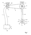
- Fig. 1 shows a schematic view of the web tension measuring device with a web 8 which is moved by a roller 17.
- the roller 17 has an axis or axis of rotation 18 on.
- the operation of the ducking machine causes the tension in the web 8 to exert a displacement force in a first direction 7 on the movable roller 17.
- the roll axis 18 of the movable roll 17, which may be a liquid-cooled or a driven roll, is therefore urged in the direction 7.
- the roller shaft 18 in turn exerts a force on a first lever arm 19 and a second lever arm 16 (see Fig. 2), both of which are fixedly connected to a pivot axis 12.
- the first and second lever arms 19, 16 thus provide torque in the pivot axis 12.
- the first pulley 5 transmits the torque by means of a belt 4 to a second pulley 3, the belt 4 preferably having a toothed inner surface.
- the rotation of the second pulley 3 transmits the torque to the same through a fixed connection with the rotational axis 14 of the counteracting drive.
- the axis of rotation 14 of the counteracting drive is connected to the drive 15, for example a motor, and thus transmits the torque to the drive 15.
- the controller 10 outputs a zero position signal to the drive 15 so that the drive 15 counteracts the torque exerted by the axis 14 of the drive, wherein the torque 20 of the drive counteracts the torque emanating from the axis 14 of the drive ,
- the torque 20 of the drive stabilizes the axis 14 of the drive.
- the axis 14 of the drive in turn prevents the rotation of the second pulley 3, which prevents the rotation of the first pulley 5 by means of the belt 4.
- the first pulley 5 prevents rotation of the pivot axis 12, and the pivot axis 12 in turn stabilizes the first and second lever arms 19, 16.
- the first and second lever arms 19, 16 stabilize the movable roller 17 so that the axle 18 remains stationary.
- the movable roller 17 exerts a second deflection force in a second direction 6, which acts the same and counter to the first deflection force, which starts from the tension in the web 8.
- the controller 10 which may be an electronic circuit or a microprocessor, reads a value representing the torque 20 to the motor 15 or axle 14 through a first connection 1. The controller then sends a zero command to the drive 15 via a second link 2, e.g. a motor that causes the drive 15 to maintain the null position so that the axle 14 does not rotate. The controller 10 then converts the value sent via the link 1, which represents the torque 20 of the drive, to a measurement of the web tension in dependence on the length of the first and second lever arms 19, 16, the diameter of the movable roller 17 and the ratio of first pulley 5 to the second pulley 3. The controller 10 outputs the measurement of the web tension as a digital signal 9.
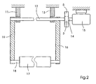
- FIG. 2 shows a schematic front view of the web tension measuring device showing the drive 15 and the second lever arm 16.
- the movable roller 17 is fixedly attached to the rotation axis 18, and the rotation axis 18 is fixed to the first and second lever arms 19, 16 and can rotate therein.
- the pivot axis 12 is shown, which is fixedly connected to the first and second lever arm 19, 16 and attached to the first and second fastening element 11, 13.
- the pivot axis 12, which rotates freely in the first and second fastening elements 11, 13, is fixedly connected to the first pulley 5.
- the belt 4 provides a connection between the first pulley 5 and the second pulley 3 (see Fig. 1).
- the second pulley 3 is fixedly connected to the axle 14 of the drive, which is connected to the drive 15.
- the controller 10 may send a position command to the drive 15 via the first link 1.
- the position command which is based on a desired change in the position of the movable roller 17, as determined in a normal compensation calculation, leads to a change in the torque 20 of the drive 15, so that the change of the torque, the first and second lever arm 19, 16 causes to rotate about the pivot axis 12 and thus the movable roller 17 allows to move.
- the drive 15 then adjusts the torque 20 of the drive by subtracting the torque required to accelerate the mechanical parts of the present invention from the torque 20 of the drive, thus recovering the torque 20 of the drive equal to the torque caused by the web tension sets.
- the device may thus serve as a web tension compensator.
- the drive 15 is preferably an electric motor with a shaft.
Abstract
Description
Die vorliegende Erfindung betrifft eine Vorrichtung und ein Verfahren zum Messen oder Steuern einer Bahnspannung gemäss den Oberbegriffen der Ansprüche 1 und 10.The present invention relates to a device and a method for measuring or controlling a web tension according to the preambles of
Eine solche Vorrichtung und so ein Verfahren sind z.B. aus JP 01 321263 bekannt.Such a device and such a method are e.g. from JP 01 321263 known.
Rollenrotationsdruckmaschinen bedrucken eine fortlaufende Materialbahn, z.B. aus Papier. In einem Druckwerk einer Druckmaschine wird die fortlaufende Bahn mit einem Bild bedruckt, dann wird die Bahn gefalzt und in Signaturen geschnitten. Der Vorgang des Bedruckens der Bahn mit einem Bild sowie das Falzen der Bahn erzeugt eine Spannung in der Bahn. Die richtige Spannung sollte während des Druck- und Falzvorgangs in der Bahn erhalten bleiben.Web-fed rotary printing machines print on a continuous web, e.g. made of paper. In a printing unit of a printing machine, the continuous web is printed with an image, then the web is folded and cut into signatures. The process of printing the web with an image as well as folding the web creates tension in the web. The correct tension should be maintained during the printing and folding process in the web.
Ein Verfahren zum Messen der richtigen Spannung verwendet eine Spannungsübertragungsvorrichtung. Die bereits existierenden Spannungsübertragungsvorrichtungen sind jedoch analoge Vorrichtungen, die eine häufige Kalibrierung benötigen und leicht beschädigt werden können, wenn sie überbelastet werden. Darüber hinaus reicht die Bandbreite der vorhandenen Spannungsübertragungsvorrichtungen für einige Anwendungen nicht aus. Des Weiteren bestehen die vorhandenen Spannungsübertragungsvorrichtungen aus Spannungsmessanordnungen, die in den Enden der Spannungswalzen befestigt sind. Die Anordnungen machen einige Anwendungen, z.B. das Messen einer Bahnspannung an einer angetriebenen Walze oder eine flüssigkeitsgekühlten Walze, schwierig, kostenintensiv oder sogar unmöglich.A method of measuring the correct voltage uses a voltage transfer device. However, the existing voltage transfer devices are analog devices that require frequent calibration and can be easily damaged when overloaded. In addition, the bandwidth of existing voltage transfer devices is insufficient for some applications. Furthermore, the existing tension transmitting devices consist of tension measuring assemblies mounted in the ends of the tensioning rollers. The arrangements make some applications, e.g. Measuring a web tension on a driven roller or a liquid-cooled roller, difficult, expensive or even impossible.
Es ist die Aufgabe der vorliegenden Erfindung eine Walze durch Entgegenwirken der Kraft, die aufgrund der Bahnspannung auf der Walze entsteht, zu stabilisieren. Eine zusätzliche und alternative Aufgabe der Erfindung ist es, eine einfachere Vorrichtung zum Erzeugen von Bahnspannungsinformationen von den Walzen zu schaffen. Noch eine weitere oder alternative Aufgabe der vorliegenden Erfindung ist es, eine Vorrichtung zu schaffen, die nicht nur als ein Kompensator, sondern auch als eine Spannungsmessvorrichtung in einem Bahnmessbereich dienen kannIt is the object of the present invention to stabilize a roll by counteracting the force generated by the web tension on the roll. An additional and alternative object of the invention is to provide a simpler apparatus for generating web tension information from the rolls. Yet another or alternative object of the present invention is to provide a device which can serve not only as a compensator but also as a tension measuring device in a path measuring range
Diese Aufgabe wird erfindungsgemäß durch die Merkmale der Ansprüche 1 und 11 gelöst. Weitere Merkmale sind in den Unteransprüchen enthalten.This object is achieved by the features of
Die vorliegende Erfindung schafft eine Vorrichtung zum Messen der Bahnspannung mit einer Walze zum Kontaktieren der Materialbahn, wobei die Walze eine Drehachse aufweist, die durch die Bahn in eine erste Richtung bewegbar ist, einem Antrieb, der mit der Walze verbunden ist, wobei der Antrieb dient, die Achse der Walze in eine zweite Richtung entgegen der ersten Richtung zu drängen, und einer Steuerung, die mit dem entgegenwirkenden Antrieb zum Messen der Bahnspannung verbunden ist.The present invention provides an apparatus for measuring web tension with a roller for contacting the web of material, the roller having an axis of rotation which is movable by the web in a first direction, a drive connected to the roller, the drive being used to urge the axis of the roller in a second direction against the first direction, and a controller connected to the counteracting drive for measuring the web tension.
Anhand der erfindungsgemäßen Walze und dem erfindungsgemäßen Antrieb kann die Bahnspannungsinformation in vorteilhafter Weise leicht und effizient ermittelt werden. Darüber hinaus ermöglicht die Steuerung der vorliegenden Erfindung, sowohl als Bandkompensator als auch als Bahnspannungsmessvorrichtung in einem gegebenen Bahnmessbereich zu dienen.On the basis of the roller according to the invention and the drive according to the invention, the web tension information can advantageously be determined easily and efficiently. In addition, the control of the present invention allows to serve both as a belt compensator and as a web tension measuring device in a given path measuring range.
Die bewegbare Walze kann eine flüssigkeitsgekühlte Walze sein. Die flüssigkeitsgekühlte Walze verbessert in vorteilhafter Weise die Leistung beim Bedrucken der Bahn.The movable roller may be a liquid-cooled roller. The liquid-cooled roll advantageously improves the performance of printing the web.
Vorzugsweise ist der entgegenwirkende Antrieb ein Motor. Der Motor schafft den Vorteil, dass die vorliegende Erfindung bei höheren Spannungen betrieben werden kann, ohne dass mehr Beschädigungen oder Staus auftreten.Preferably, the counteracting drive is a motor. The motor provides the advantage that the present invention can be operated at higher voltages without causing more damage or jamming.
Die Steuerung ist vorzugsweise eine elektronische Schaltung. Die Verwendung einer elektronischen Schaltung erübrigt das häufige Kalibrieren der vorliegenden Erfindung.The controller is preferably an electronic circuit. The use of electronic circuitry eliminates the need for frequent calibration of the present invention.
Die Bahnspannungsmessvorrichtung kann eine Vielzahl von Hebelarmen, eine Schwenkachse, eine Vielzahl von Riemenscheiben, einen Riemen, eine Achse des Antriebs und/oder eine Drehachse umfassen, wobei jede Vorrichtung mechanisch mit dem entgegenwirkenden Antrieb verbunden ist.The web tension measuring device may comprise a plurality of lever arms, a pivot axis, a plurality of pulleys, a belt, an axis of the drive, and / or an axis of rotation, each device being mechanically connected to the counteracting drive.
Die vorliegende Erfindung schafft auch ein Verfahren zum Messen der Spannung in einer Bahn, welches die folgenden Verfahrensschritte umfasst:
- Führen einer Bahn über eine Walze mit einer Achse, wobei die Achse der Walze in eine erste Richtung bewegbar ist;
- Entgegenwirken der Bewegung der Achse in eine zweite Richtung entgegen der ersten Richtung; und
- Messen einer entgegenwirkenden Kraft oder einer Variablen, um die Bahnspannung zu bestimmen.
- Guiding a web over a roll having an axis, the axis of the roll being movable in a first direction;
- Counteracting the movement of the axle in a second direction counter to the first direction; and
- Measuring a counteracting force or variable to determine the web tension.
Die Walze kann bei dem Verfahren zum Messen der Spannung in der Bahn ortsfest bleiben. Diese Tatsache erleichtert es in vorteilhafter Weise, Informationen über die Bahnspannung zu erhalten.The roller may remain stationary in the method of measuring tension in the web. This fact advantageously makes it easier to obtain information about the web tension.
In einer bevorzugten Ausführungsform der Erfindung kann die Walze um eine Schwenkachse drehbar in einem Hebel oder Hebelarm angeordnet sein, wobei ein Bahnkompensatoralgorithmus die erwünschte Position der Walze bestimmt. Die Drehung um die Schwenkachse schafft den Vorteil, dass die Walze die Spannungsmessfunktion und die Funktion als Bahn- oder Bandkompensator ausführen kann.In a preferred embodiment of the invention, the roller may be rotatable about a pivot axis in a lever or lever arm, wherein a path compensator algorithm determines the desired position of the roller. The rotation about the pivot axis provides the advantage that the roller can perform the voltage measuring function and the function as a web or belt compensator.
Die Erfindung wird nachfolgend mit Bezug auf die Zeichnungen anhand bevorzugter Ausführungsformen beschrieben.The invention will be described below with reference to the drawings based on preferred embodiments.
Es zeigen:
- Fig. 1
- eine schematische Seitenansicht der Bahnspannungsmessvorrichtung mit einer Bahn;
- Fig. 2
- eine schematische Frontansicht der Bahnspannungsmessvorrichtung mit dem entgegenwirkenden Antrieb und dem zweiten Hebelarm.
- Fig. 1
- a schematic side view of the web tension measuring device with a web;
- Fig. 2
- a schematic front view of the web tension measuring device with the counteracting drive and the second lever arm.
Fig. 1 zeigt eine schematische Ansicht der Bahnspannungsmessvorrichtung mit einer Bahn 8, die über eine Walze 17 bewegt wird. Die Walze 17 weist eine Achse oder Drehachse 18 auf. Der Betrieb der Duckmaschine führt dazu, dass die Spannung in der Bahn 8 eine Verdrängungskraft in eine erste Richtung 7 auf die bewegbare Walze 17 ausübt. Die Walzenachse 18 der bewegbaren Walze 17, die eine mit einer Flüssigkeit gekühlte oder eine angetriebene Walze sein kann, wird daher in die Richtung 7 gedrängt. Die Walzenachse 18 übt ihrerseits eine Kraft auf einen ersten Hebelarm 19 und einen zweiten Hebelarm 16 (s. Fig. 2) aus, die beide fest mit einer Schwenkachse 12 verbunden sind. Der erste und der zweite Hebelarm 19, 16 schaffen so ein Drehmoment in der Schwenkachse 12. Die Schwenkachse 12, die in einem ersten Befestigungselement 11 und einem zweiten Befestigungselement 13 (s. Fig. 2) befestigt ist, gibt dieses Drehmoment an eine erste Riemenscheibe 5 weiter. Die erste Riemenscheibe 5 überträgt das Drehmoment mittels eines Riemens 4 auf eine zweite Riemenscheibe 3, wobei der Riemen 4 vorzugsweise eine gezahnte innere Oberfläche aufweist. Die Drehung der zweiten Riemenscheibe 3 überträgt das Drehmoment durch eine feste Verbindung mit der Drehachse 14 des entgegenwirkenden Antriebs auf dieselbe. Die Drehachse 14 des entgegenwirkenden Antriebs ist mit dem Antrieb 15, z.B. einem Motor, verbunden und überträgt so das Drehmoment auf den Antrieb 15.Fig. 1 shows a schematic view of the web tension measuring device with a
Wie nachfolgend beschrieben schafft der Antrieb 15, der von der Steuerung 10 gesteuert wird, ein genau entgegengesetztes Drehmoment zu der Drehachse 14, so dass sich die Achse 14 nicht bewegt. Die Steuerung 10 gibt ein Nullpositionssignal an den Antrieb 15 aus, so dass der Antrieb 15 dem Drehmoment, das von der Achse 14 des Antriebs ausgeht, entgegenwirkt, wobei das Drehmoment 20 des Antriebs dem Drehmoment, das von der Achse 14 des Antriebs ausgeht, entgegenwirkt. Somit stabilisiert das Drehmoment 20 des Antriebs die Achse 14 des Antriebs. Die Achse 14 des Antriebs verhindert ihrerseits die Drehung der zweiten Riemenscheibe 3, die die Drehung der ersten Riemenscheibe 5 mittels des Riemens 4 verhindert. Die erste Riemenscheibe 5 verhindert die Drehung der Schwenkachse 12, und die Schwenkachse 12 stabilisiert ihrerseits den ersten und den zweiten Hebelarm 19, 16. Der erste und der zweite Hebelarm 19, 16 stabilisieren die bewegbare Walze 17, so dass die Achse 18 ortsfest bleibt. Die bewegbare Walze 17 übt eine zweite Auslenkungskraft in eine zweite Richtung 6 aus, die gleich und entgegen der ersten Auslenkungskraft, die von der Spannung in der Bahn 8 ausgeht, wirkt.As described below, the
Die Steuerung 10, die eine elektronische Schaltung sein kann oder ein Mikroprozessor, liest einen Wert, der durch eine erste Verbindung 1 das Drehmoment 20 auf den Motor 15 oder die Achse 14 wiedergibt. Die Steuerung sendet dann einen Null-Befehl mittels einer zweiten Verbindung 2 an den Antrieb 15, z.B. einen Motor, der bewirkt, dass der Antrieb 15 die Nullposition beibehält, so dass sich die Achse 14 nicht dreht. Die Steuerung 10 konvertiert dann den über die Verbindung 1 gesandten Wert, der das Drehmoment 20 des Antriebs wiedergibt, in eine Messung der Bahnspannung in Abhängigkeit von der Länge des ersten und zweiten Hebelarms 19, 16, des Durchmessers der bewegbaren Walze 17 und des Verhältnisses der ersten Riemenscheibe 5 zur zweiten Riemenscheibe 3. Die Steuerung 10 gibt die Messung der Bahnspannung als ein digitales Signal 9 aus.The
Fig. 2 zeigt eine schematische Frontansicht der Bahnspannungsmessvorrichtung, die den Antrieb 15 und den zweiten Hebelarm 16 zeigt. Die bewegliche Walze 17 ist fest an Drehachse 18 angebracht, und die Drehachse 18 ist an dem ersten und zweiten Hebelarm 19, 16 befestigt und kann sich in diesen drehen. Ebenso ist die Schwenkachse 12 gezeigt, die fest mit dem ersten und zweiten Hebelarm 19, 16 verbunden und an dem ersten und zweiten Befestigungselement 11, 13 angebracht ist. Die Schwenkachse 12, die sich frei in dem ersten und zweiten Befestigungselement 11, 13 dreht, ist fest mit der ersten Riemenscheibe 5 verbunden. Der Riemen 4 schafft eine Verbindung zwischen der ersten Riemenscheibe 5 und der zweiten Riemenscheibe 3 (s. Fig. 1). Die zweite Riemenscheibe 3 ist fest mit der Achse 14 des Antriebs verbunden, die mit dem Antrieb 15 verbunden ist.FIG. 2 shows a schematic front view of the web tension measuring device showing the
In einer anderen Ausführungsform kann die Steuerung 10 über die erste Verbindung 1 einen Positionsbefehl an den Antrieb 15 schicken. Der Positionsbefehl, der auf einer gewünschten Veränderung in der Position der bewegbaren Walze 17 beruht, wie sie bei einer normalen Kompensationsberechnung bestimmt wird, führt zu einer Veränderung des Drehmoments 20 des Antriebs 15, so dass die Veränderung des Drehmoments den ersten und zweiten Hebelarm 19, 16 dazu bringt, sich um die Schwenkachse 12 zu drehen und damit der bewegbaren Walze 17 ermöglicht sich zu bewegen. Der Antrieb 15 stellt das Drehmoment 20 des Antriebs dann ein, indem er das zur Beschleunigung der mechanischen Teile der vorliegenden Erfindung notwendige Drehmoment von dem Drehmoment 20 des Antriebs abzieht und so das Drehmoment 20 des Antriebs wieder gleich des von der Bahnspannung verursachten Drehmoments setzt. Die Vorrichtung kann so als ein Bahnspannungskompensator dienen.In another embodiment, the
Der Antrieb 15 ist vorzugsweise ein Elektromotor mit einer Welle.The
- 11
- erste Verbindungfirst connection
- 22
- zweite Verbindungsecond connection
- 33
- zweite Riemenscheibesecond pulley
- 44
- Riemenbelt
- 55
- erste Riemenscheibefirst pulley
- 66
- zweite Richtungsecond direction
- 77
- erste Richtungfirst direction
- 88th
- Bahntrain
- 99
- digitales Signaldigital signal
- 1010
- Steuerungcontrol
- 1111
- erstes Befestigungselementfirst fastening element
- 1212
- Schwenkachseswivel axis
- 1313
- zweites Befestigungselementsecond fastening element
- 1414
- Drehachseaxis of rotation
- 1515
- Antriebdrive
- 1616
- zweiter Hebelarmsecond lever arm
- 1717
- Walzeroller
- 1818
- Drehachseaxis of rotation
- 1919
- erster Hebelarmfirst lever arm
- 2020
- Drehmomenttorque
Claims (13)
- Device for measuring a web tension with
a roller (17) for contacting a material web (8), wherein the roller (17) provides a rotational axis (18), which can be moved by the web (8) in a first direction (7);
with a drive (15), which is connected to the roller (17), wherein the drive (15) is used to displace the roller (17) in a second direction (6) contrary to the first direction (7); and
with a control unit (10), which is connected to the drive (15), in order to measure the web tension,
characterised in that
the control unit (10) controls the drive (15) of the roller (17) in such a manner that the rotational axis (18) remains fixed in position during the measurement of the web tension, and the web tension is measured in that the control unit (10) reads a value, which reproduces the torque (20) on the drive (15) and that the control unit (10) converts the measured value (20) into the measurement of the web tension. - Device for measuring the web tension according to claim 1,
characterised in that
the roller (17) is a liquid-cooled roller. - Device for measuring the web tension according to claim 1 or 2,
characterised in that
the drive (15) is a motor. - Device for measuring the web tension according to any one of the preceding claims,
characterised in that
the control unit (10) is an electronic circuit. - Device for measuring the web tension according to any one of the preceding claims,
characterised in that
the device also comprises a plurality of lever arms (16, 19), each lever arm (16, 19) being mechanically connected to the drive (15), and the plurality of lever arms (16, 19) bearing the roller (17). - Device for measuring the web tension according to any one of the preceding claims,
characterised in that
the device also comprises a swivelling axis (12), which is mechanically connected to the drive (15). - Device for measuring the web tension according to any one of the preceding claims,
characterised in that
the device also comprises a plurality of belt pulleys (3, 5), each belt pulley (3, 5) being mechanically connected to the drive (15). - Device for measuring the web tension according to any one of the preceding claims,
characterised in that
the device also comprises a belt (4), which is connected to at least one of the belt pulleys (3, 5). - Device for measuring the web tension according to any one of the preceding claims,
characterised in that
the drive (15) has an axis (14). - Printing machine,
characterised in that
it comprises a device according to any one of the preceding claims. - Method for measuring the web tension comprising the following procedural stages:- guiding a web (8) over a roller (17), wherein the roller (17) has an axis (18), which can be moved in a first direction (7);- counteracting the movement of the axis (18) in a second direction (6) contrary to the first direction (7); and- measuring a counteracting force or a variable, in order to determine a web tension,characterised in that
the axis (18) of the roller (17) remains fixed in position, and the web tension is measured in that a control unit (10) reads a value, which reproduces the force or the variable, and that the control unit (10) converts the measured value (20) into the measurement of the web tension. - Method for measuring the tension according to claim 11,
characterised in that
the roller (17), in a lever or lever arm (16, 19), is rotatable about a swivelling axis (12). - Method for measuring the tension according to claim 12,
characterised in that
the method also comprises the stage of moving the axis (18) of the roller (17) on the basis of a web-compensation algorithm.
Applications Claiming Priority (2)
| Application Number | Priority Date | Filing Date | Title |
|---|---|---|---|
| US09/726,240 US6752013B2 (en) | 2000-11-29 | 2000-11-29 | Device and method for web tension measurement |
| US726240 | 2000-11-29 |
Publications (3)
| Publication Number | Publication Date |
|---|---|
| EP1211206A2 EP1211206A2 (en) | 2002-06-05 |
| EP1211206A3 EP1211206A3 (en) | 2003-10-15 |
| EP1211206B1 true EP1211206B1 (en) | 2006-06-21 |
Family
ID=24917760
Family Applications (1)
| Application Number | Title | Priority Date | Filing Date |
|---|---|---|---|
| EP01126547A Expired - Lifetime EP1211206B1 (en) | 2000-11-29 | 2001-11-15 | Method and device for measuring the web tension |
Country Status (5)
| Country | Link |
|---|---|
| US (1) | US6752013B2 (en) |
| EP (1) | EP1211206B1 (en) |
| JP (1) | JP4488154B2 (en) |
| AT (1) | ATE330891T1 (en) |
| DE (2) | DE10156206A1 (en) |
Families Citing this family (11)
| Publication number | Priority date | Publication date | Assignee | Title |
|---|---|---|---|---|
| US6993964B2 (en) * | 2004-02-04 | 2006-02-07 | The Procter & Gamble Company | Method of determining a modulus of elasticity of a moving web material |
| DE102007015785A1 (en) * | 2007-03-30 | 2008-10-02 | Man Roland Druckmaschinen Ag | Method and device for determining the web tension or the web tension in a printing material web |
| US8757535B2 (en) | 2010-10-25 | 2014-06-24 | The Procter & Gamble Company | Method for reducing web feed rate variations induced by parent roll geometry variations |
| US8733687B2 (en) | 2010-10-25 | 2014-05-27 | The Procter & Gamble Company | Alternative apparatus for reducing web feed rate variations induced by parent roll geometry variations |
| US9434573B2 (en) | 2010-10-25 | 2016-09-06 | The Procter & Gamble Company | Alternative method for reducing web feed rate variations induced by parent roll geometry variations |
| US8733686B2 (en) | 2010-10-25 | 2014-05-27 | The Procter & Gamble Company | Alternative apparatus for reducing web feed rate variations induced by parent roll geometry variations |
| US8733685B2 (en) | 2010-10-25 | 2014-05-27 | The Procter & Gamble Company | Apparatus for reducing web feed rate variations induced by parent roll geometry variations |
| US9434572B2 (en) | 2010-10-25 | 2016-09-06 | The Procter & Gamble Company | Alternative method for reducing web feed rate variations induced by parent roll geometry variations |
| US8740130B2 (en) | 2010-10-25 | 2014-06-03 | The Procter & Gamble Company | Alternative method for reducing web feed rate variations induced by parent roll geometry variations |
| US9816906B2 (en) | 2014-04-25 | 2017-11-14 | Honeywell International Inc. | Apparatus and method for stretch measurements of tissue webs |
| DE102020134370A1 (en) | 2020-12-21 | 2022-06-23 | Inficon Gmbh | Gas leak detection device and gas leak detection method for detecting a gas leak in a test object |
Family Cites Families (26)
| Publication number | Priority date | Publication date | Assignee | Title |
|---|---|---|---|---|
| GB995874A (en) | 1961-04-25 | 1965-06-23 | Asea Ab | Means for regulating the tension in webs, bands, sheets, tracks or the like |
| GB1048175A (en) | 1965-07-09 | 1966-11-16 | Plamag Plauener Druckmaschinen | Paper web tension governor |
| DE1774714A1 (en) | 1968-08-21 | 1971-10-21 | Allmaenna Svenska Elek Ska Ab | Arrangement for rewinding tape-shaped material |
| DE2127993C2 (en) | 1971-06-05 | 1982-08-26 | Gebrüder Sucker, 4050 Mönchengladbach | Device for regulating the winding tension of goods guided in web form |
| US3777959A (en) | 1972-02-25 | 1973-12-11 | Du Pont | Apparatus for monitoring and controlling tension in an advancing flexible elongate material |
| CH574363A5 (en) | 1973-11-13 | 1976-04-15 | Bobst Fils Sa J | |
| DE2510451C3 (en) * | 1975-03-11 | 1984-04-26 | Agfa-Gevaert Ag, 5090 Leverkusen | Device for mechanical scanning of local thickenings in paper and film webs |
| US4144700A (en) * | 1976-12-14 | 1979-03-20 | Murata Kikai Kabushiki Kaisha | False twisting apparatus |
| US4159808A (en) | 1978-01-06 | 1979-07-03 | Butler Automatic, Inc. | Variable ratio winder |
| IT1119102B (en) | 1979-06-07 | 1986-03-03 | Cerutti Spa Off Mec | ELECTRONIC ADJUSTMENT AND CONTROL DEVICE FOR THE CONTROL OF ROLLING FEED ROTARY MACHINES |
| IT1173847B (en) | 1984-03-15 | 1987-06-24 | Ansaldo Sistemi Ind Spa | HOT LAMINATION BELT TYPE REGULATOR |
| DE3443357C1 (en) * | 1984-11-28 | 1986-04-17 | Vits-Maschinenbau Gmbh, 4018 Langenfeld | Web tension control device on a vertical dryer for webs |
| JPS61146827A (en) * | 1984-12-17 | 1986-07-04 | Murata Mach Ltd | Automatic inspection device of yarn ending apparatus |
| JPH01321263A (en) | 1988-06-22 | 1989-12-27 | Hitachi Ltd | Method of controlling tension |
| DE3940744C2 (en) | 1989-12-09 | 1994-03-17 | Hansmann Erich Dipl Ing | Roller for a device for processing web or sheet material |
| DE4003659A1 (en) | 1990-02-07 | 1991-08-08 | Kokes Michael Dipl Ing Fh | Constant stretch control for moving films - having extension of film monitored and adjusted to programmed extension at process point |
| DE4019108C2 (en) | 1990-06-15 | 1994-08-18 | Stahlkontor Maschinenbau | Device for regulating or keeping constant the freely selectable and speed-independent tensile force of sheet or thread-like winding material made of plastic, paper, textile, metals or the like |
| DE4027938A1 (en) | 1990-09-04 | 1992-03-05 | Minnesota Mining & Mfg | DEVICE FOR MOVING RECORDING MATERIAL IN A PRINTER DEVICE |
| US6001199A (en) * | 1990-10-24 | 1999-12-14 | Hunter Douglas Inc. | Method for manufacturing a fabric light control window covering |
| DE4039108C1 (en) | 1990-12-07 | 1992-04-16 | Man Roland Druckmaschinen Ag, 6050 Offenbach, De | |
| US5472127A (en) | 1992-07-21 | 1995-12-05 | Kawasaki Steel Corporation | Strip tension control apparatus |
| DE4232635C2 (en) | 1992-09-29 | 1996-12-05 | Siemens Matsushita Components | Method and device for regulating the film tension in the manufacture of electrical winding capacitors |
| DE9315076U1 (en) | 1993-01-22 | 1994-02-03 | Escher Wyss Gmbh | Device for determining the web tension |
| EP0652104B1 (en) * | 1993-11-05 | 2002-04-10 | MAN Roland Druckmaschinen AG | Printing unit for waterless offset printing |
| JP2819283B2 (en) | 1996-12-24 | 1998-10-30 | 株式会社東京機械製作所 | Continuous paper running tension control device |
| FR2761673B1 (en) | 1997-04-02 | 1999-06-18 | Soc Et De Machines Pour Les Ar | DEVICE FOR AUTOMATICALLY CONTROLLING THE TENSION OF A WEB OF MATERIALS IN A PRINTING MACHINE |
-
2000
- 2000-11-29 US US09/726,240 patent/US6752013B2/en not_active Expired - Fee Related
-
2001
- 2001-11-15 DE DE10156206A patent/DE10156206A1/en not_active Withdrawn
- 2001-11-15 AT AT01126547T patent/ATE330891T1/en not_active IP Right Cessation
- 2001-11-15 DE DE50110232T patent/DE50110232D1/en not_active Expired - Lifetime
- 2001-11-15 EP EP01126547A patent/EP1211206B1/en not_active Expired - Lifetime
- 2001-11-29 JP JP2001364925A patent/JP4488154B2/en not_active Expired - Fee Related
Also Published As
| Publication number | Publication date |
|---|---|
| EP1211206A2 (en) | 2002-06-05 |
| JP2002234650A (en) | 2002-08-23 |
| DE10156206A1 (en) | 2002-06-13 |
| US20020062689A1 (en) | 2002-05-30 |
| ATE330891T1 (en) | 2006-07-15 |
| DE50110232D1 (en) | 2006-08-03 |
| US6752013B2 (en) | 2004-06-22 |
| JP4488154B2 (en) | 2010-06-23 |
| EP1211206A3 (en) | 2003-10-15 |
Similar Documents
| Publication | Publication Date | Title |
|---|---|---|
| EP1211206B1 (en) | Method and device for measuring the web tension | |
| DE1290406B (en) | Device for guiding a running web | |
| EP0741015A2 (en) | Circumferential and lateral register adjustment device of the plate cylinder | |
| DE10158985A1 (en) | Stretch regulation assembly in intake of printing machines has material thickness measuring device, device to apply tension to material, and sensors to detect material spool thickness and angular position | |
| EP0913352A2 (en) | Buckling folder and method for registration control of a buckling folder | |
| EP1483444A1 (en) | Method and device for reducing vibrations in rotating components | |
| CH697762B1 (en) | An apparatus for positioning a roller in an inking or dampening unit of a rotary printing machine. | |
| EP0859730B1 (en) | Folding device | |
| DE2936768C2 (en) | Adjustable folding device for rotary printing machines | |
| EP1303404B1 (en) | Method for regulation of a web tension in a rotary print machine | |
| DE3721900C2 (en) | ||
| DE102008048659A1 (en) | Apparatus and method for aligning sheets | |
| EP1127826A2 (en) | Device for correcting the lateral position of a printed material web in a rotary printing machine | |
| EP0426022A2 (en) | Plate cylinder of a printing press | |
| EP1415944B1 (en) | Apparatus for the adjustment of pressing rollers and/or cutting blades in folding machines | |
| EP0652105A1 (en) | Sheet transfer cylinder for a printing press | |
| EP0815496B1 (en) | Device for the positionally accurate synchronization of the parallel course of recording carrier webs in an electrographic printing device | |
| EP0464616A1 (en) | Traction device for a rotary printing machine | |
| DE19710530B4 (en) | Apparatus for producing or further processing sliver | |
| DE4410132C2 (en) | Flexographic printing machine, in particular for multi-color printing | |
| DE19602050A1 (en) | Drive and exchange unit for sheet supply roll of vertical tubular pouch packing machine | |
| DE19510728C1 (en) | Recording web storage device for electrographic printer | |
| DE10229457B4 (en) | Pull roller with adjustable pull ring | |
| WO2003086760A1 (en) | Characterization, detection of a reference number, and selection of suitable winding materials for rollers of a printing press | |
| EP1523446B1 (en) | Strand guide device |
Legal Events
| Date | Code | Title | Description |
|---|---|---|---|
| PUAI | Public reference made under article 153(3) epc to a published international application that has entered the european phase |
Free format text: ORIGINAL CODE: 0009012 |
|
| AK | Designated contracting states |
Kind code of ref document: A2 Designated state(s): AT BE CH CY DE DK ES FI FR GB GR IE IT LI LU MC NL PT SE TR |
|
| AX | Request for extension of the european patent |
Free format text: AL;LT;LV;MK;RO;SI |
|
| PUAL | Search report despatched |
Free format text: ORIGINAL CODE: 0009013 |
|
| AK | Designated contracting states |
Kind code of ref document: A3 Designated state(s): AT BE CH CY DE DK ES FI FR GB GR IE IT LI LU MC NL PT SE TR |
|
| AX | Request for extension of the european patent |
Extension state: AL LT LV MK RO SI |
|
| RIC1 | Information provided on ipc code assigned before grant |
Ipc: 7B 41F 13/22 B Ipc: 7B 65H 23/04 A Ipc: 7G 01L 5/10 B |
|
| 17P | Request for examination filed |
Effective date: 20030915 |
|
| AKX | Designation fees paid |
Designated state(s): AT BE CH CY DE DK ES FI FR GB GR IE IT LI LU MC NL PT SE TR |
|
| 17Q | First examination report despatched |
Effective date: 20040727 |
|
| RAP1 | Party data changed (applicant data changed or rights of an application transferred) |
Owner name: GOSS INTERNATIONAL AMERICAS, INC. |
|
| GRAP | Despatch of communication of intention to grant a patent |
Free format text: ORIGINAL CODE: EPIDOSNIGR1 |
|
| GRAS | Grant fee paid |
Free format text: ORIGINAL CODE: EPIDOSNIGR3 |
|
| GRAA | (expected) grant |
Free format text: ORIGINAL CODE: 0009210 |
|
| AK | Designated contracting states |
Kind code of ref document: B1 Designated state(s): AT BE CH CY DE DK ES FI FR GB GR IE IT LI LU MC NL PT SE TR |
|
| PG25 | Lapsed in a contracting state [announced via postgrant information from national office to epo] |
Ref country code: IT Free format text: LAPSE BECAUSE OF FAILURE TO SUBMIT A TRANSLATION OF THE DESCRIPTION OR TO PAY THE FEE WITHIN THE PRESCRIBED TIME-LIMIT;WARNING: LAPSES OF ITALIAN PATENTS WITH EFFECTIVE DATE BEFORE 2007 MAY HAVE OCCURRED AT ANY TIME BEFORE 2007. THE CORRECT EFFECTIVE DATE MAY BE DIFFERENT FROM THE ONE RECORDED. Effective date: 20060621 Ref country code: NL Free format text: LAPSE BECAUSE OF FAILURE TO SUBMIT A TRANSLATION OF THE DESCRIPTION OR TO PAY THE FEE WITHIN THE PRESCRIBED TIME-LIMIT Effective date: 20060621 Ref country code: IE Free format text: LAPSE BECAUSE OF FAILURE TO SUBMIT A TRANSLATION OF THE DESCRIPTION OR TO PAY THE FEE WITHIN THE PRESCRIBED TIME-LIMIT Effective date: 20060621 Ref country code: FI Free format text: LAPSE BECAUSE OF FAILURE TO SUBMIT A TRANSLATION OF THE DESCRIPTION OR TO PAY THE FEE WITHIN THE PRESCRIBED TIME-LIMIT Effective date: 20060621 |
|
| REG | Reference to a national code |
Ref country code: GB Ref legal event code: FG4D Free format text: NOT ENGLISH |
|
| REG | Reference to a national code |
Ref country code: CH Ref legal event code: EP |
|
| REG | Reference to a national code |
Ref country code: CH Ref legal event code: NV Representative=s name: KIRKER & CIE SA |
|
| REG | Reference to a national code |
Ref country code: IE Ref legal event code: FG4D Free format text: LANGUAGE OF EP DOCUMENT: GERMAN |
|
| REF | Corresponds to: |
Ref document number: 50110232 Country of ref document: DE Date of ref document: 20060803 Kind code of ref document: P |
|
| GBT | Gb: translation of ep patent filed (gb section 77(6)(a)/1977) |
Effective date: 20060726 |
|
| PG25 | Lapsed in a contracting state [announced via postgrant information from national office to epo] |
Ref country code: SE Free format text: LAPSE BECAUSE OF FAILURE TO SUBMIT A TRANSLATION OF THE DESCRIPTION OR TO PAY THE FEE WITHIN THE PRESCRIBED TIME-LIMIT Effective date: 20060921 Ref country code: DK Free format text: LAPSE BECAUSE OF FAILURE TO SUBMIT A TRANSLATION OF THE DESCRIPTION OR TO PAY THE FEE WITHIN THE PRESCRIBED TIME-LIMIT Effective date: 20060921 |
|
| PG25 | Lapsed in a contracting state [announced via postgrant information from national office to epo] |
Ref country code: ES Free format text: LAPSE BECAUSE OF FAILURE TO SUBMIT A TRANSLATION OF THE DESCRIPTION OR TO PAY THE FEE WITHIN THE PRESCRIBED TIME-LIMIT Effective date: 20061002 |
|
| PG25 | Lapsed in a contracting state [announced via postgrant information from national office to epo] |
Ref country code: PT Free format text: LAPSE BECAUSE OF FAILURE TO SUBMIT A TRANSLATION OF THE DESCRIPTION OR TO PAY THE FEE WITHIN THE PRESCRIBED TIME-LIMIT Effective date: 20061121 |
|
| ET | Fr: translation filed | ||
| PG25 | Lapsed in a contracting state [announced via postgrant information from national office to epo] |
Ref country code: MC Free format text: LAPSE BECAUSE OF NON-PAYMENT OF DUE FEES Effective date: 20061130 Ref country code: BE Free format text: LAPSE BECAUSE OF NON-PAYMENT OF DUE FEES Effective date: 20061130 |
|
| NLV1 | Nl: lapsed or annulled due to failure to fulfill the requirements of art. 29p and 29m of the patents act | ||
| REG | Reference to a national code |
Ref country code: IE Ref legal event code: FD4D |
|
| PLBE | No opposition filed within time limit |
Free format text: ORIGINAL CODE: 0009261 |
|
| STAA | Information on the status of an ep patent application or granted ep patent |
Free format text: STATUS: NO OPPOSITION FILED WITHIN TIME LIMIT |
|
| 26N | No opposition filed |
Effective date: 20070322 |
|
| BERE | Be: lapsed |
Owner name: GOSS INTERNATIONAL AMERICAS, INC. Effective date: 20061130 |
|
| PG25 | Lapsed in a contracting state [announced via postgrant information from national office to epo] |
Ref country code: AT Free format text: LAPSE BECAUSE OF NON-PAYMENT OF DUE FEES Effective date: 20061115 |
|
| PG25 | Lapsed in a contracting state [announced via postgrant information from national office to epo] |
Ref country code: GR Free format text: LAPSE BECAUSE OF FAILURE TO SUBMIT A TRANSLATION OF THE DESCRIPTION OR TO PAY THE FEE WITHIN THE PRESCRIBED TIME-LIMIT Effective date: 20060922 |
|
| PG25 | Lapsed in a contracting state [announced via postgrant information from national office to epo] |
Ref country code: LU Free format text: LAPSE BECAUSE OF NON-PAYMENT OF DUE FEES Effective date: 20061115 Ref country code: TR Free format text: LAPSE BECAUSE OF FAILURE TO SUBMIT A TRANSLATION OF THE DESCRIPTION OR TO PAY THE FEE WITHIN THE PRESCRIBED TIME-LIMIT Effective date: 20060621 |
|
| PG25 | Lapsed in a contracting state [announced via postgrant information from national office to epo] |
Ref country code: CY Free format text: LAPSE BECAUSE OF FAILURE TO SUBMIT A TRANSLATION OF THE DESCRIPTION OR TO PAY THE FEE WITHIN THE PRESCRIBED TIME-LIMIT Effective date: 20060621 |
|
| PGFP | Annual fee paid to national office [announced via postgrant information from national office to epo] |
Ref country code: FR Payment date: 20101202 Year of fee payment: 10 |
|
| PGFP | Annual fee paid to national office [announced via postgrant information from national office to epo] |
Ref country code: DE Payment date: 20101126 Year of fee payment: 10 Ref country code: CH Payment date: 20101124 Year of fee payment: 10 |
|
| PGFP | Annual fee paid to national office [announced via postgrant information from national office to epo] |
Ref country code: GB Payment date: 20101124 Year of fee payment: 10 |
|
| REG | Reference to a national code |
Ref country code: CH Ref legal event code: PL |
|
| GBPC | Gb: european patent ceased through non-payment of renewal fee |
Effective date: 20111115 |
|
| PG25 | Lapsed in a contracting state [announced via postgrant information from national office to epo] |
Ref country code: CH Free format text: LAPSE BECAUSE OF NON-PAYMENT OF DUE FEES Effective date: 20111130 Ref country code: LI Free format text: LAPSE BECAUSE OF NON-PAYMENT OF DUE FEES Effective date: 20111130 |
|
| REG | Reference to a national code |
Ref country code: FR Ref legal event code: ST Effective date: 20120731 |
|
| REG | Reference to a national code |
Ref country code: DE Ref legal event code: R119 Ref document number: 50110232 Country of ref document: DE Effective date: 20120601 |
|
| PG25 | Lapsed in a contracting state [announced via postgrant information from national office to epo] |
Ref country code: GB Free format text: LAPSE BECAUSE OF NON-PAYMENT OF DUE FEES Effective date: 20111115 |
|
| PG25 | Lapsed in a contracting state [announced via postgrant information from national office to epo] |
Ref country code: FR Free format text: LAPSE BECAUSE OF NON-PAYMENT OF DUE FEES Effective date: 20111130 |
|
| PG25 | Lapsed in a contracting state [announced via postgrant information from national office to epo] |
Ref country code: DE Free format text: LAPSE BECAUSE OF NON-PAYMENT OF DUE FEES Effective date: 20120601 |