EP1187148B1 - Dauer magnet-dünnschicht und hestellungsverfahren - Google Patents
Dauer magnet-dünnschicht und hestellungsverfahren Download PDFInfo
- Publication number
- EP1187148B1 EP1187148B1 EP01906188A EP01906188A EP1187148B1 EP 1187148 B1 EP1187148 B1 EP 1187148B1 EP 01906188 A EP01906188 A EP 01906188A EP 01906188 A EP01906188 A EP 01906188A EP 1187148 B1 EP1187148 B1 EP 1187148B1
- Authority
- EP
- European Patent Office
- Prior art keywords
- thin film
- permanent magnet
- rare earth
- multilayer structure
- layer
- Prior art date
- Legal status (The legal status is an assumption and is not a legal conclusion. Google has not performed a legal analysis and makes no representation as to the accuracy of the status listed.)
- Expired - Lifetime
Links
- 238000000034 method Methods 0.000 title description 8
- 230000008569 process Effects 0.000 title description 3
- 230000005291 magnetic effect Effects 0.000 claims abstract description 126
- 229910045601 alloy Inorganic materials 0.000 claims abstract description 86
- 239000000956 alloy Substances 0.000 claims abstract description 86
- 229910052761 rare earth metal Inorganic materials 0.000 claims abstract description 65
- 150000002910 rare earth metals Chemical class 0.000 claims abstract description 65
- 239000000758 substrate Substances 0.000 claims abstract description 46
- 239000003870 refractory metal Substances 0.000 claims abstract description 39
- 239000000463 material Substances 0.000 claims abstract description 29
- RKTYLMNFRDHKIL-UHFFFAOYSA-N copper;5,10,15,20-tetraphenylporphyrin-22,24-diide Chemical compound [Cu+2].C1=CC(C(=C2C=CC([N-]2)=C(C=2C=CC=CC=2)C=2C=CC(N=2)=C(C=2C=CC=CC=2)C2=CC=C3[N-]2)C=2C=CC=CC=2)=NC1=C3C1=CC=CC=C1 RKTYLMNFRDHKIL-UHFFFAOYSA-N 0.000 claims abstract description 21
- 229910052726 zirconium Inorganic materials 0.000 claims abstract description 16
- 229910052719 titanium Inorganic materials 0.000 claims abstract description 15
- 229910052804 chromium Inorganic materials 0.000 claims abstract description 14
- 229910052735 hafnium Inorganic materials 0.000 claims abstract description 14
- 229910052750 molybdenum Inorganic materials 0.000 claims abstract description 14
- 229910052758 niobium Inorganic materials 0.000 claims abstract description 14
- 229910052715 tantalum Inorganic materials 0.000 claims abstract description 14
- 229910052721 tungsten Inorganic materials 0.000 claims abstract description 14
- 229910052720 vanadium Inorganic materials 0.000 claims abstract description 14
- 239000000470 constituent Substances 0.000 claims abstract description 7
- 239000010409 thin film Substances 0.000 claims description 63
- 238000004519 manufacturing process Methods 0.000 claims description 8
- 230000015572 biosynthetic process Effects 0.000 claims description 6
- 230000008018 melting Effects 0.000 claims description 4
- 238000002844 melting Methods 0.000 claims description 4
- 239000010410 layer Substances 0.000 description 136
- 239000010408 film Substances 0.000 description 36
- 229910001172 neodymium magnet Inorganic materials 0.000 description 33
- 238000000151 deposition Methods 0.000 description 20
- 230000008021 deposition Effects 0.000 description 20
- 230000004907 flux Effects 0.000 description 19
- 150000001875 compounds Chemical class 0.000 description 18
- 230000005415 magnetization Effects 0.000 description 18
- 230000000052 comparative effect Effects 0.000 description 17
- 239000013078 crystal Substances 0.000 description 14
- 229910000521 B alloy Inorganic materials 0.000 description 8
- 238000000137 annealing Methods 0.000 description 8
- 238000010438 heat treatment Methods 0.000 description 7
- 238000006243 chemical reaction Methods 0.000 description 6
- 238000004544 sputter deposition Methods 0.000 description 5
- 239000000919 ceramic Substances 0.000 description 4
- 238000005137 deposition process Methods 0.000 description 4
- 239000002356 single layer Substances 0.000 description 4
- 238000007736 thin film deposition technique Methods 0.000 description 4
- 238000004364 calculation method Methods 0.000 description 3
- 230000006872 improvement Effects 0.000 description 3
- 239000000696 magnetic material Substances 0.000 description 3
- 229910052751 metal Inorganic materials 0.000 description 3
- 239000002184 metal Substances 0.000 description 3
- 239000000203 mixture Substances 0.000 description 3
- 238000004663 powder metallurgy Methods 0.000 description 3
- 229910052779 Neodymium Inorganic materials 0.000 description 2
- 229910052777 Praseodymium Inorganic materials 0.000 description 2
- 230000008878 coupling Effects 0.000 description 2
- 238000010168 coupling process Methods 0.000 description 2
- 238000005859 coupling reaction Methods 0.000 description 2
- 239000011261 inert gas Substances 0.000 description 2
- 239000006247 magnetic powder Substances 0.000 description 2
- 238000001755 magnetron sputter deposition Methods 0.000 description 2
- 229910000889 permalloy Inorganic materials 0.000 description 2
- OKTJSMMVPCPJKN-UHFFFAOYSA-N Carbon Chemical compound [C] OKTJSMMVPCPJKN-UHFFFAOYSA-N 0.000 description 1
- 229910000976 Electrical steel Inorganic materials 0.000 description 1
- 229910018104 Ni-P Inorganic materials 0.000 description 1
- 229910018536 Ni—P Inorganic materials 0.000 description 1
- 229910000831 Steel Inorganic materials 0.000 description 1
- 230000004075 alteration Effects 0.000 description 1
- 229910052799 carbon Inorganic materials 0.000 description 1
- 230000007423 decrease Effects 0.000 description 1
- 230000003247 decreasing effect Effects 0.000 description 1
- 238000011161 development Methods 0.000 description 1
- 230000000694 effects Effects 0.000 description 1
- 238000005516 engineering process Methods 0.000 description 1
- 230000005294 ferromagnetic effect Effects 0.000 description 1
- 239000007789 gas Substances 0.000 description 1
- 239000011521 glass Substances 0.000 description 1
- 239000012535 impurity Substances 0.000 description 1
- 238000000608 laser ablation Methods 0.000 description 1
- 230000005381 magnetic domain Effects 0.000 description 1
- 230000005389 magnetism Effects 0.000 description 1
- 238000010587 phase diagram Methods 0.000 description 1
- 239000010453 quartz Substances 0.000 description 1
- 229910001404 rare earth metal oxide Inorganic materials 0.000 description 1
- 238000012827 research and development Methods 0.000 description 1
- 229910052594 sapphire Inorganic materials 0.000 description 1
- 239000010980 sapphire Substances 0.000 description 1
- VYPSYNLAJGMNEJ-UHFFFAOYSA-N silicon dioxide Inorganic materials O=[Si]=O VYPSYNLAJGMNEJ-UHFFFAOYSA-N 0.000 description 1
- 239000010959 steel Substances 0.000 description 1
- 239000000126 substance Substances 0.000 description 1
- 229910052723 transition metal Inorganic materials 0.000 description 1
- 238000007738 vacuum evaporation Methods 0.000 description 1
- XLYOFNOQVPJJNP-UHFFFAOYSA-N water Substances O XLYOFNOQVPJJNP-UHFFFAOYSA-N 0.000 description 1
Images

Classifications
-
- G—PHYSICS
- G11—INFORMATION STORAGE
- G11B—INFORMATION STORAGE BASED ON RELATIVE MOVEMENT BETWEEN RECORD CARRIER AND TRANSDUCER
- G11B5/00—Recording by magnetisation or demagnetisation of a record carrier; Reproducing by magnetic means; Record carriers therefor
- G11B5/62—Record carriers characterised by the selection of the material
- G11B5/64—Record carriers characterised by the selection of the material comprising only the magnetic material without bonding agent
- G11B5/66—Record carriers characterised by the selection of the material comprising only the magnetic material without bonding agent the record carriers consisting of several layers
- G11B5/672—Record carriers characterised by the selection of the material comprising only the magnetic material without bonding agent the record carriers consisting of several layers having different compositions in a plurality of magnetic layers, e.g. layer compositions having differing elemental components or differing proportions of elements
-
- H—ELECTRICITY
- H01—ELECTRIC ELEMENTS
- H01F—MAGNETS; INDUCTANCES; TRANSFORMERS; SELECTION OF MATERIALS FOR THEIR MAGNETIC PROPERTIES
- H01F10/00—Thin magnetic films, e.g. of one-domain structure
- H01F10/08—Thin magnetic films, e.g. of one-domain structure characterised by magnetic layers
- H01F10/10—Thin magnetic films, e.g. of one-domain structure characterised by magnetic layers characterised by the composition
- H01F10/12—Thin magnetic films, e.g. of one-domain structure characterised by magnetic layers characterised by the composition being metals or alloys
- H01F10/14—Thin magnetic films, e.g. of one-domain structure characterised by magnetic layers characterised by the composition being metals or alloys containing iron or nickel
-
- B—PERFORMING OPERATIONS; TRANSPORTING
- B82—NANOTECHNOLOGY
- B82Y—SPECIFIC USES OR APPLICATIONS OF NANOSTRUCTURES; MEASUREMENT OR ANALYSIS OF NANOSTRUCTURES; MANUFACTURE OR TREATMENT OF NANOSTRUCTURES
- B82Y25/00—Nanomagnetism, e.g. magnetoimpedance, anisotropic magnetoresistance, giant magnetoresistance or tunneling magnetoresistance
-
- B—PERFORMING OPERATIONS; TRANSPORTING
- B82—NANOTECHNOLOGY
- B82Y—SPECIFIC USES OR APPLICATIONS OF NANOSTRUCTURES; MEASUREMENT OR ANALYSIS OF NANOSTRUCTURES; MANUFACTURE OR TREATMENT OF NANOSTRUCTURES
- B82Y40/00—Manufacture or treatment of nanostructures
-
- G—PHYSICS
- G11—INFORMATION STORAGE
- G11B—INFORMATION STORAGE BASED ON RELATIVE MOVEMENT BETWEEN RECORD CARRIER AND TRANSDUCER
- G11B5/00—Recording by magnetisation or demagnetisation of a record carrier; Reproducing by magnetic means; Record carriers therefor
- G11B5/62—Record carriers characterised by the selection of the material
- G11B5/73—Base layers, i.e. all non-magnetic layers lying under a lowermost magnetic recording layer, e.g. including any non-magnetic layer in between a first magnetic recording layer and either an underlying substrate or a soft magnetic underlayer
- G11B5/7368—Non-polymeric layer under the lowermost magnetic recording layer
-
- G—PHYSICS
- G11—INFORMATION STORAGE
- G11B—INFORMATION STORAGE BASED ON RELATIVE MOVEMENT BETWEEN RECORD CARRIER AND TRANSDUCER
- G11B5/00—Recording by magnetisation or demagnetisation of a record carrier; Reproducing by magnetic means; Record carriers therefor
- G11B5/84—Processes or apparatus specially adapted for manufacturing record carriers
- G11B5/8404—Processes or apparatus specially adapted for manufacturing record carriers manufacturing base layers
-
- H—ELECTRICITY
- H01—ELECTRIC ELEMENTS
- H01F—MAGNETS; INDUCTANCES; TRANSFORMERS; SELECTION OF MATERIALS FOR THEIR MAGNETIC PROPERTIES
- H01F1/00—Magnets or magnetic bodies characterised by the magnetic materials therefor; Selection of materials for their magnetic properties
- H01F1/01—Magnets or magnetic bodies characterised by the magnetic materials therefor; Selection of materials for their magnetic properties of inorganic materials
- H01F1/03—Magnets or magnetic bodies characterised by the magnetic materials therefor; Selection of materials for their magnetic properties of inorganic materials characterised by their coercivity
- H01F1/032—Magnets or magnetic bodies characterised by the magnetic materials therefor; Selection of materials for their magnetic properties of inorganic materials characterised by their coercivity of hard-magnetic materials
- H01F1/04—Magnets or magnetic bodies characterised by the magnetic materials therefor; Selection of materials for their magnetic properties of inorganic materials characterised by their coercivity of hard-magnetic materials metals or alloys
- H01F1/047—Alloys characterised by their composition
- H01F1/053—Alloys characterised by their composition containing rare earth metals
- H01F1/055—Alloys characterised by their composition containing rare earth metals and magnetic transition metals, e.g. SmCo5
- H01F1/057—Alloys characterised by their composition containing rare earth metals and magnetic transition metals, e.g. SmCo5 and IIIa elements, e.g. Nd2Fe14B
-
- H—ELECTRICITY
- H01—ELECTRIC ELEMENTS
- H01F—MAGNETS; INDUCTANCES; TRANSFORMERS; SELECTION OF MATERIALS FOR THEIR MAGNETIC PROPERTIES
- H01F10/00—Thin magnetic films, e.g. of one-domain structure
- H01F10/08—Thin magnetic films, e.g. of one-domain structure characterised by magnetic layers
- H01F10/10—Thin magnetic films, e.g. of one-domain structure characterised by magnetic layers characterised by the composition
- H01F10/12—Thin magnetic films, e.g. of one-domain structure characterised by magnetic layers characterised by the composition being metals or alloys
- H01F10/126—Thin magnetic films, e.g. of one-domain structure characterised by magnetic layers characterised by the composition being metals or alloys containing rare earth metals
-
- H—ELECTRICITY
- H01—ELECTRIC ELEMENTS
- H01F—MAGNETS; INDUCTANCES; TRANSFORMERS; SELECTION OF MATERIALS FOR THEIR MAGNETIC PROPERTIES
- H01F41/00—Apparatus or processes specially adapted for manufacturing or assembling magnets, inductances or transformers; Apparatus or processes specially adapted for manufacturing materials characterised by their magnetic properties
- H01F41/14—Apparatus or processes specially adapted for manufacturing or assembling magnets, inductances or transformers; Apparatus or processes specially adapted for manufacturing materials characterised by their magnetic properties for applying magnetic films to substrates
- H01F41/30—Apparatus or processes specially adapted for manufacturing or assembling magnets, inductances or transformers; Apparatus or processes specially adapted for manufacturing materials characterised by their magnetic properties for applying magnetic films to substrates for applying nanostructures, e.g. by molecular beam epitaxy [MBE]
- H01F41/302—Apparatus or processes specially adapted for manufacturing or assembling magnets, inductances or transformers; Apparatus or processes specially adapted for manufacturing materials characterised by their magnetic properties for applying magnetic films to substrates for applying nanostructures, e.g. by molecular beam epitaxy [MBE] for applying spin-exchange-coupled multilayers, e.g. nanostructured superlattices
-
- H—ELECTRICITY
- H01—ELECTRIC ELEMENTS
- H01F—MAGNETS; INDUCTANCES; TRANSFORMERS; SELECTION OF MATERIALS FOR THEIR MAGNETIC PROPERTIES
- H01F10/00—Thin magnetic films, e.g. of one-domain structure
- H01F10/32—Spin-exchange-coupled multilayers, e.g. nanostructured superlattices
- H01F10/324—Exchange coupling of magnetic film pairs via a very thin non-magnetic spacer, e.g. by exchange with conduction electrons of the spacer
- H01F10/3286—Spin-exchange coupled multilayers having at least one layer with perpendicular magnetic anisotropy
-
- Y—GENERAL TAGGING OF NEW TECHNOLOGICAL DEVELOPMENTS; GENERAL TAGGING OF CROSS-SECTIONAL TECHNOLOGIES SPANNING OVER SEVERAL SECTIONS OF THE IPC; TECHNICAL SUBJECTS COVERED BY FORMER USPC CROSS-REFERENCE ART COLLECTIONS [XRACs] AND DIGESTS
- Y10—TECHNICAL SUBJECTS COVERED BY FORMER USPC
- Y10S—TECHNICAL SUBJECTS COVERED BY FORMER USPC CROSS-REFERENCE ART COLLECTIONS [XRACs] AND DIGESTS
- Y10S428/00—Stock material or miscellaneous articles
- Y10S428/90—Magnetic feature
-
- Y—GENERAL TAGGING OF NEW TECHNOLOGICAL DEVELOPMENTS; GENERAL TAGGING OF CROSS-SECTIONAL TECHNOLOGIES SPANNING OVER SEVERAL SECTIONS OF THE IPC; TECHNICAL SUBJECTS COVERED BY FORMER USPC CROSS-REFERENCE ART COLLECTIONS [XRACs] AND DIGESTS
- Y10—TECHNICAL SUBJECTS COVERED BY FORMER USPC
- Y10T—TECHNICAL SUBJECTS COVERED BY FORMER US CLASSIFICATION
- Y10T428/00—Stock material or miscellaneous articles
- Y10T428/11—Magnetic recording head
- Y10T428/1107—Magnetoresistive
Definitions
- the present invention relates to a thin film permanent magnet and a method for producing the thin film.
- the present invention relates to a thin film permanent magnet suitably used for a micro-motor, a micro-actuator, a device for applying a biased magnetic field to a magneto-resistive device, a magnetic recording medium, or the like.
- the magnetic anisotropy of the Nd-Fe-B based magnet formed by thin film deposition technique is lower than that of a bulk-like permanent magnet manufactured by a method such as powder metallurgy, or other means.
- highly anisotropic magnetic materials can be made by executing the orientation of magnetic powder in a magnetic field or by utilizing slide deformation.
- an unintended impurity phase such as rare earth metal oxide or the like is often mixed or generated in a thin film having the tetragonal R 2 Fe 14 B compound as a main phase. This is one of the factors preventing the properties of a thin film permanent magnet from being improved.
- Japanese Laid-Open Patent Publication No. 7-6916 discloses a thin film permanent magnet in which a protection film is disposed on a rare earth alloy magnetic thin film.
- Japanese Laid-Open patent Publication No. 9-219313 discloses a thin film permanent magnet in which protection films are disposed on and under a rare earth alloy magnetic thin film.
- These protection films prevent the reaction between the rare earth alloy magnetic thin film and the air or a substrate, and exercise a function of preventing the magnetic properties of the rare earth alloy magnetic thin film from being deteriorated due to the reaction.
- the objects of the above-mentioned prior arts are to suppress the reaction caused by the direct contact between the rare earth alloy magnetic film and the substrate or the air and to prevent the alteration of the magnetic film caused by the reaction.
- the metallurgical microstructure of the rare earth alloy magnetic film is not sufficiently controlled. Therefore, the coercive force is lower than a value expected from a crystal magnetic anisotropic energy originally included in the tetragonal R 2 Fe 14 B compound, and a sufficient residual magnetic flux density is not obtained.
- the present invention has been conducted in view of the above-described prior art. It is an object of the present invention to provide a high-performance thin film permanent magnet having both of high coercive force and high residual magnetic flux density by controlling the metallurgical microstructure. It is another object of the present invention to provide a rotating machine and a magnetic recording medium using such a thin film permanent magnet.
- the thin film permanent magnet of the present invention is a thin film permanent magnet having a multilayer structure including four or more layers in which a refractory metal layer and a rare earth alloy magnetic layer are alternately deposited, and characterized in that the refractory metal layer is formed from at least one kind of material selected from a group consisting of Ti, V, Cr, Zr, Nb, Mo, Hf, Ta, and W, and has a thickness of not less than 5 nm nor more than 50 nm, and the rare earth alloy magnetic layer has tetragonal R 2 Fe 14 B as a primary constituent phase (R is Nd and/or Pr), and has a thickness of not less than 50 nm nor more than 500 nm, wherein the rare earth alloy magnetic layer has magnetic anisotropy.
- the refractory metal layer is formed from at least one kind of material selected from a group consisting of Ti, V, Cr, Zr, Nb, Mo, Hf, Ta, and W, and has a thickness of not less than 5 n
- a ratio (B r2 /B r1 ) of a residual magnetic flux density (B r2 ) in a direction perpendicular to an in-plane direction to a residual magnetic flux density (B r1 ) in the in-plane direction of the rare earth alloy magnetic layer is 2 or more.
- the number of the rare earth alloy magnetic layers included in the multilayer structure is 3 or more.
- a ratio (t n /t m ) of a total thickness (t n ) of the refractory metal layers to a total thickness (t m ) of the rare earth alloy magnetic layers included in the multilayer structure satisfies a condition of 0.01 ⁇ (t n /t m ) ⁇ 0.3.
- a buffer layer is formed between a substrate for supporting the multilayer structure and the multilayer structure.
- the buffer layer is formed from at least one kind of material selected from a group consisting of Ti, V, Cr, Zr, Nb, Mo, Hf, Ta, and W.
- a protection layer is formed as an uppermost layer of the multilayer structure.
- the protection layer may be formed from at least one kind of material selected from a group consisting of Ti, V, Cr, Zr, Nb, Mo, Hf, Ta, and W.
- the method for producing a thin film permanent magnet of the present invention includes the steps of: preparing a substrate formed from a material having a melting point of 300°C or more; and forming, on the substrate, a multilayer structure including four or more layers in which a refractory metal layer having a thickness of not less than 5 nm nor more than 50 nm formed from at least one kind of material selected from a group consisting of Ti, V, Cr, Zr, Nb, Mo, Hf, Ta, and W and a rare earth alloy magnetic layer having a thickness of not less than 50 nm nor more than 500 nm and having tetragonal R 2 Fe 14 B (R is Nd and/or Pr) as a primary constituent phase are alternately deposited, wherein the rare earthalloy magnetic layer has magnetic anisotropy.
- the rare earth alloy magnetic layer is formed while a temperature of the substrate is adjusted to be in the range of not less than 300°C nor more than 800°C.
- the rare earth alloy magnetic layer may be formed while a temperature of the substrate is adjusted to be lower than 300°C, and after the multilayer structure is formed on the substrate, the multilayer structure may be heated to temperatures of not less than 400°C nor more than 800°C.
- a preferred embodiment includes a step of applying a magnetic field to the multilayer structure during or after the formation of the multilayer structure.
- a rotating machine according to the present invention is characterized by including any one of the above-mentioned thin film permanent magnets.
- a magnetic recording medium according to the present invention is characterized by including any one of the above-mentioned thin films of permanent magnet.
- the inventor of the present invention examined permanent magnetic properties for various films in which a R-Fe-B based alloy layer including tetragonal R 2 Fe 14 B compound (R is Nd and/or Pr) as a main phase and a refractory metal layer were alternately deposited.
- R is Nd and/or Pr
- the inventor found that the metallurgical microstructure of the R-Fe-B based alloy layer was strongly affected by the kinds of the refractory metal layers disposed on and under the R-Fe-B based alloy layer and the thickness of the R-Fe-B based alloy layer, and conceived the present invention.
- the thin film permanent magnet according to the present invention is a permanent magnet film including a multilayer structure of four or more layers in which a refractory metal layer and a rare earth alloy magnetic layer are alternately deposited.
- the refractory metal layer is formed from at least one kind of material selected from a group consisting of Ti, V, Cr, Zr, Nb, Mo, Hf, Ta, and W, and has a thickness of not less than 5 nm nor more than 50 nm.
- the rare earth alloy magnetic layer includes tetragonal R 2 Fe 14 B as a primary constituent phase and has a thickness of not less than 50 nm nor more than 500 nm.
- R includes Nd, Pr, or both of Nd and Pr. Co or a transition metal element such as Ni may be substituted for part of Fe.
- the inventor found that a permanent magnet even in the shape of a thin film in which intensive perpendicular magnetic anisotropy and high coercive force were both achieved could be manufactured.
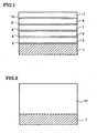
- FIG. 1 illustrates a cross-sectional configuration of the thin film permanent magnet in this embodiment.
- a thin film permanent magnet shown in FIG. 1 has a multilayer structure of 10 layers in which refractory metal layers 2 , 4 , 6 , 8 , and 10 and rare earth alloy magnetic layers 3 , 5 , 7 , 9 , and 11 are alternately deposited.
- the multilayer structure is disposed on a substrate 1.
- the refractory metal layers 2 , 4 , 6 , 8 , and 10 are formed from at least one kind of material selected from a group consisting of Ti, V, Cr, Zr, Nb, Mo, Hf, Ta and W, and each has a thickness of not less than 5 nm nor more than 50 nm.
- a primary constituent phase of the rare earth alloy magnetic layers 3 , 5 , 7 , 9 , and 11 is tetragonal R 2 Fe 14 B (R is Nd and/or Pr), and the thickness thereof is adjusted to be not less than 50 nm nor more than 500 nm.
- R is Nd and/or Pr
- a tetragonal R 2 Fe 14 B compound which is a hard magnetic phase mainly affects magnetic properties.
- a most preferable thickness of each of the rare earth alloy magnetic layers is not less than 50 nm nor more than 200 nm. It is preferred that the number of the rare earth alloy magnetic layers in the multilayer structure be 3 or more.
- a thin refractory metal layer (the refractory metal layer 4 ) is always disposed.
- the refractory metal layer 2 exists between the substrate 1 and the rare earth alloy magnetic layer 3 which is positioned as the lowermost layer.
- the refractory metal layer 2 may be omitted.
- a refractory metal layer is not formed on the rare earth alloy magnetic layer 11 which is positioned as the uppermost layer.
- another refractory metal layer may be disposed on the rare earth alloy magnetic layer 11 .
- the material of refractory metal layers should not be arbitrarily selected, but it is necessary that the refractory metal layers are formed from at least one kind of material selected from a group consisting of Ti, V, Cr, Zr, Nb, Mo, Hf, Ta, and W.
- the R 2 Fe 14 B compound in the rare earth alloy magnetic layer has a tendency that if the compound is in contact with a refractory metal layer formed from the above-mentioned material during a deposition step or an annealing step (heat treatment step), the axis of easy magnetization thereof is oriented in a direction perpendicular to a face of the substrate.
- the above-mentioned refractory metal layer has functions of increasing the magnetic anisotropy of the rare earth alloy magnetic layer and of improving the residual magnetic flux density B r perpendicular to a plane.
- FIG. 2 shows a cross-sectional configuration of a prior-art thin film permanent magnet in which a single rare earth alloy layer 12 is formed on a substrate 1 . As is seen from FIGS.
- the total thickness of the rare earth alloy magnetic layers 3 , 5 , 7 , 9 , and 11 in this embodiment is substantially equal to the thickness of the rare earth alloy magnetic layer 12 in FIG. 2 .
- the respective rare earth alloy magnetic layers 3 , 5 , 7 , 9 , and 11 in FIG. 1 are separated by the provision of the refractory metal layers 4 , 6 , 8 , and 10 .
- the crystal growth of the tetragonal R 2 Fe 14 B compound is suppressed, and the metallurgical structure is sufficiently fined. This significantly contributes to the increase in coercive force.
- each of the refractory metal layers 2 , 4 , 6 , 8 , and 10 was lower than 5 nm, the above-mentioned crystal orientation effect could not be sufficiently exhibited.
- the thickness of each of the refractory metal layers 2 , 4 , 6 , 8 , and 10 exceeded 50 nm, nonmagnetic refractory atoms were largely penetrated into the rare earth alloy magnetic layers, and the crystal magnetic anisotropic energy of the magnetic layers was disadvantageously decreased.
- the magnetic coupling between the two upper and lower rare earth alloy magnetic layers becomes weak. This is not preferable.
- the problem in the magnetic coupling is insignificant in the cases where the refractory metal layer is positioned as the lowermost layer or positioned as the uppermost layer of the multilayer structure.
- the refractory metal layer in such a position exerts a significant function as a protection layer, so that it may have a thickness in excess of 500 nm.
- the ratio (t n /t m ) of the total thickness (t n ) of the refractory metal layers 2 , 4 , 6 , 8 , and 10 to the total thickness (t m ) of the rare earth alloy magnetic layers 3 , 5 , 7 , 9 , and 11 constituting one thin film permanent magnet satisfy a condition of 0.01 ⁇ (t n /t m ) ⁇ 0.3.
- the R-Fe-B alloy layer is primarily composed of tetragonal R 2 Fe 14 B compound.
- the tetragonal R 2 Fe 14 B compound has the largest crystal magnetic anisotropic energy, and hence realizes high coercive force. Accordingly, it is desirable that a fraction of the R 2 Fe 14 B compound in the rare earth alloy magnetic layer be as large as possible.
- the coercive force depends on the metallurgical microstructure and the crystal grain diameter of the R 2 Fe 14 B compound.
- the rare earth alloy magnetic layers are separated by the refractory metal layers in the film thickness direction, so that the crystal growth of tetragonal R 2 Fe 14 B is limited by the thickness of each of the magnetic layers. Therefore, by adjusting the rare earth alloy magnetic layers, the crystal grain diameter of the R 2 Fe 14 B compound can be optimized, and the coercive force can be increased.
- the thickness of each rare earth alloy magnetic layer is preferably set to 500 nm or less.
- the thickness of each rare earth alloy magnetic layer is set to 50 nm or more.
- a substrate formed from a material having a melting point of 300°C or more is prepared.
- the substrate is subjected to annealing at 300°C or more during the formation of a multilayer structure or after the formation.
- the material for the substrate is required to have a melting point of 300°C or more and to withstand the above-mentioned annealing.
- the substrate be formed from a material which is chemically stable and resistant to reaction with an atmospheric gas or a deposited material during the deposition of the thin film or during a heating process.
- a Si wafer, a Mo plate, stainless, various kinds of steel plates, a sapphire plate, a quartz plate, a glass plate, an Al 2 O 3 -TiC complex ceramics plate, and the like can be suitably used.
- a buffer layer for suppressing such reaction covers an upper face of the substrate, there arises no problem.
- a refractory metal layer formed from at least one kind of material selected from a group consisting of Ti, V, Cr, Zr, Nb, Mo, Hf, Ta, and W may be used, or another stable film may be used.
- the thickness of the buffer layer is not limited to 50 nm or less.
- a structure in which a refractory metal layer and a rare earth alloy magnetic layer are alternately deposited is formed on a substrate by using a thin film deposition technique such as sputtering.
- a thin film deposition technique such as sputtering.
- a method for heating the substrate in the formation of the multilayer structure is arbitrarily selected.
- the substrate may be directly or indirectly heated by a sheathed heater or an infrared lamp heater.
- the heating process performed after the formation of the multilayer structure is desired to be executed in vacuum or an inert gas atmosphere so as not to oxidize the thin film permanent magnet.
- the period of time for the heating process varies depending on the annealing temperatures. For example, when the annealing temperature is 600°C, it is preferred that a heating process for about 0.2 to 2 hours be performed.
- a rare earth metal or an alloy including a rare earth metal which constitutes the rare earth alloy magnetic layer is easily oxidized, so that the deposition process is desirably conducted in a high vacuum atmosphere or an inert gas atmosphere.
- vacuum evaporation and laser ablation are listed as preferable thin film deposition methods. Chemical, physical, and metallographic properties of the deposited layers by these methods depend on various conditions in the deposition process. Since the R-Fe-B alloy easily becomes amorphous, it is necessary to control the substrate temperature in the deposition process so as to be in the above-mentioned range, or to crystallize the alloy by a heating process after the deposition process.
- a material which is chemically stable and is suitable as a yoke member for example, a silicon steel plate, a permalloy plate, or the like is desirably used for the substrate material.
- a protection film formed by a diamond-like carbon is desirably disposed on the thin film permanent magnet.
- a backing layer of Ni-P, a permalloy film, or the like is desirably disposed between the thin film permanent magnet and the substrate.
- Samples Nos. 2 to 8 are examples of the present invention, and Samples Nos. 1 and 9 to 13 are comparative examples.
- the deposition of the Ta, Mb, Zr, or Ti layer pure metal target was used. The deposition was performed in conditions of throw-in power of 3 to 6 W/cm 2 , Ar pressure of 0.5 Pa, and deposition rate of 0.1 to 0.8 nm/s.
- the deposition of the Nd-Fe-B alloy layer cast alloy having a composition of Nd 14 Fe 71 B 15 in atom ratio was used as a target. The deposition was performed in conditions of throw-in power of 10 W/cm 2 , Ar pressure of 0.5 Pa, and deposition rate of 3 nm/s.
- Substrate/[Ti(20nm)/Nd-Fe-B(200nm)]x5" shown in a box of " Multilayer Structure” in Table 1 means that " a structure in which a Ti layer having a thickness of 20 nm and an Nd-Fe-B alloy layer having a thickness of 200 nm are alternately deposited is formed on a substrate, and the numbers of layers of the Ti layers and the Nd-Fe-B alloy layers included in the deposited structure are 5, respectively” .
- the coercive forces H cJ of all the examples in the perpendicular to the film plan direction are larger than the coercive force H cJ of the comparative example (Sample No. 1) in which only a single layer of Nd-Fe-B alloy layer is formed.
- the residual magnetic flux densities B r2 in the direction perpendicular to the film plane are higher than the residual magnetic flux densities B r1 in the film in-plane direction, and hence a so-called perpendicular magnetic anisotropy is exhibited.
- Samples Nos the cases of Samples Nos.
- a ratio (B r2 /B r1 ) of the residual magnetic flux density B r2 in the direction perpendicular to the film plane to the residual magnetic flux density B r1 in the film in-plane direction is a high value, i.e., 5 or more.
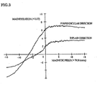
- the magnetization curve of the comparative example for Sample No. 1 is shown in FIG. 3
- the magnetization curve of the example for Sample No. 3 is shown in FIG. 4 .
- the residual magnetic flux density B r2 in the perpendicular direction in the embodiment is remarkably higher than the residual magnetic flux density B r2 in the perpendicular direction in the single layer of Nd-Fe-B alloy layer, and it is found that the perpendicular magnetic anisotropy is improved.
- Sample No. 15 is an example of the present invention and Sample No. 14 is a comparative example.
- the deposition of the Ta layer pure metal target was used. The deposition was performed in conditions of throw-in power of 6 W/cm 2 , Ar pressure of 0.5 Pa, and deposition rate of 0.8 nm/s.
- the deposition of the Pr-Fe-B alloy layer cast alloy having a composition of Pr 14 Fe 72 B 14 in atom ratio was used as a target. The deposition was performed in conditions of throw-in power of 10 W/cm 2 , Ar pressure of 0.5 Pa, and deposition rate of 3 nm/s.
- the coercive forces H cJ of the example are larger than the coercive forces H cJ of the comparative example (Sample No. 14) in which only a single layer of Pr-Fe-B alloy layer is formed.
- the residual magnetic flux density B r2 in a direction perpendicular to the film plane is extremely higher than the residual magnetic flux density B r1 in the film in-plane direction, and hence perpendicular magnetic anisotropy is exhibited.
- Sample No. 17 is an example of the present invention and Sample No. 16 is a comparative example.
- the deposition of the Ta layer pure metal target was used. The deposition was performed in conditions of incident power of 6 W/cm 2 , Ar pressure of 0.5 Pa, and deposition rate of 0.8 nm/s.
- the deposition of the Nd-Fe-B alloy layer cast alloy having a composition of Nd 14 Fe 71 B 15 in atom ratio was used as a target. The deposition was performed in conditions of throw-in power of 10 W/cm 2 , Ar pressure of 0.5 Pa, and deposition rate of 3 nm/s.
- the coercive forces H cJ of the example are significantly larger than the coercive forces H cJ of the comparative example (Sample No. 16) in which only a single layer of Nd-Fe-B alloy layer is formed.
- the residual magnetic flux density B r2 in a direction perpendicular to the film plane is extremely higher than the residual magnetic flux density B r1 in the film in-plane direction, and hence perpendicular magnetic anisotropy is exhibited.
- the thin film permanent magnet of the present invention can exert high coercive force and perpendicular magnetic anisotropy
- crystal orientation of tetragonal R 2 Fe 14 B compound is improved, and anisotropic magnet having high residual magnetic flux density in a direction perpendicular to a film plane can be realized.
- the metallurgical microstructure of the tetragonal R 2 Fe 14 B compound is made to be fine, so that the improvement in coercive force can be achieved.
Landscapes
- Engineering & Computer Science (AREA)
- Chemical & Material Sciences (AREA)
- Nanotechnology (AREA)
- Crystallography & Structural Chemistry (AREA)
- Power Engineering (AREA)
- Manufacturing & Machinery (AREA)
- Physics & Mathematics (AREA)
- General Physics & Mathematics (AREA)
- Condensed Matter Physics & Semiconductors (AREA)
- Inorganic Chemistry (AREA)
- Spectroscopy & Molecular Physics (AREA)
- Thin Magnetic Films (AREA)
- Physical Vapour Deposition (AREA)
- Permanent Field Magnets Of Synchronous Machinery (AREA)
- Magnetic Heads (AREA)
- Hard Magnetic Materials (AREA)
Claims (13)
- Dünnfilm-Dauermagnet mit einer Mehrschichtstruktur, einschließlich vier oder mehr Schichten, wobei eine feuerfeste Metallschicht (2, 4, 6, 8, 10) und eine magnetische Seltenerdlegierungsschicht (3, 5, 7, 9, 11) abwechselnd abgeschieden sind, wobei die feuerfeste Metallschicht (2, 4, 6, 8, 10) aus wenigstens einer Materialart gebildet ist, gewählt aus einer Gruppe bestehend aus Ti, V, Cr, Zr, Nb, Mo, Hf, Ta und W, und eine Dicke von nicht weniger als 5 nm und nicht mehr als 50 nm aufweist, und
die magnetische Seltenerdlegierungsschicht (3, 5, 7, 9, 11) tetragonales R2Fe14B als eine primäre Bestandteilphase (R ist Nd und/oder Pr) aufweist und eine Dicke von nicht weniger als 50 nm und nicht mehr als 500 nm aufweist,
wobei die Seltenerdlegierungsschicht (3, 5, 7, 9, 11) magnetische Anisotropie aufweist. - Dünnfilm-Dauermagnet nach Anspruch 1, wobei die Anzahl der magnetischen Seltenerdlegierungsschichten (3, 5, 7, 9, 11), welche in der Mehrschichtstruktur enthalten sind, 3 oder mehr beträgt.
- Dünnfilm-Dauermagnet nach einem der Ansprüche 1 oder 2, wobei ein Verhältnis (tn/tm) einer Gesamtdicke (tn) der feuerfesten Metallschichten (2, 4, 6, 8, 10) zu einer Gesamtdicke (tm) der magnetischen Seltenerdlegierungsschichten (3, 5, 7, 9, 11), welche in der Mehrschichtstruktur enthalten sind, eine Bedingung von 0,01 ≤ (tn/tm) ≤ 0,3 erfüllt.
- Dünnfilm-Dauermagnet nach einem der Ansprüche 1 bis 3, wobei eine Pufferschicht zwischen einem Substrat zum Unterstützen der Mehrschichtstruktur und der Mehrschichtstruktur gebildet ist.
- Dünnflim-Dauermagnet nach Anspruch 4, wobei die Pufferschicht aus wenigstens einer Materialart gebildet ist, gewählt aus der Gruppe bestehend aus Ti, V, Cr, Zr, Nb, Mo, Hf, Ta, und W.
- Dünnfilm-Dauermagnet nach einem der Ansprüche 1 bis 3, wobei eine Schutzschicht als eine oberste Schicht der Mehrschichtstruktur gebildet ist.
- Dünnfilm-Dauermagnet nach Anspruch 6, wobei die Schutzschicht aus wenigstens einer Materialart gebildet ist, gewählt aus der Gruppe bestehend aus Ti, V, Cr, Zr, Nb, Mo, Hf, Ta, und W.
- Verfahren zur Herstellung eines Dünnfilm-Dauermagneten, umfassend die Schritte:Herstellen eines Substrates, gebildet aus einem Material mit einem Schmelzpunkt von 300°C oder mehr, undBilden einer Mehrschichtstruktur auf dem Substrat, welche vier oder mehr Schichten umfasst, wobei eine feuerfeste Metallschicht (2, 4, 6, 8, 10) mit einer Dicke von nicht weniger als 5 nm und nicht mehr als 50 nm aus wenigstens einer Materialart gebildet wird, gewählt aus einer Gruppe bestehend aus Ti, V, Cr, Zr, Nb, Mo, Hf, Ta, und W, und einer magnetischen Seltenerdlegierungsschicht (3, 5, 7, 9, 11) mit einer Dicke von nicht weniger als 50 nm und nicht mehr als 500 nm und mit tetragonalem R2Fe14B (R ist Nd und/oder Pr) als eine primäre Bestandteilphase, abwechseln abgeschieden werden, wobei die magnetische Seltenerdlegierungsschicht (3, 5, 7, 9, 11) magnetische Anisotropie aufweist
- Verfahren zur Herstellung eines Dünnfilm-Dauermagneten nach Anspruch 8, wobei während des Schrittes des Formens der Mehrschichtstruktur auf dem Substrat, die magnetische Seltenerdlegierungsschicht gebildet wird, während eine Temperatur des Substrats auf einen Bereich von nicht weniger als 300°C und nicht mehr als 800°C eingestellt wird.
- Verfahren zur Herstellung eines Dünnfilm-Dauermagneten nach Anspruch 8, wobei, während des Schrittes des Formens der Mehrschichtstruktur auf dem Substrat, die magnetische Seltenerdlegierungsschicht (3, 5, 7, 9, 11) gebildet wird, während eine Temperatur des Substrats auf weniger als 300°C eingestellt wird, und
nachdem die Mehrschichtstruktur auf dem Substrat gebildet wurde, die Mehrschichtstruktur auf Temperaturen von nicht weniger als 400°C und nicht mehr als 800°C erwärmt wird. - Verfahren zur Herstellung eines Dünnfilm-Dauermagneten nach einem der Ansprüche 8 bis 10, des weiteren umfassend den Schritt des Anlegens eines Magnetfeldes an die Mehrschichtstruktur während oder nach der Bildung der Mehrschichtstruktur.
- Rotationsvorrichtung einschließlich eines Dünnfilm-Dauermagneten gemäß einem der Ansprüche 1 bis 7.
- Magnetisches Aufzeichnungsmedium einschließlich eines Dünnfilm-Dauermagneten gemäß einem der Ansprüche 1 bis 7.
Applications Claiming Priority (3)
| Application Number | Priority Date | Filing Date | Title |
|---|---|---|---|
| JP2000044175A JP4337209B2 (ja) | 2000-02-22 | 2000-02-22 | 永久磁石薄膜およびその製造方法 |
| JP2000044175 | 2000-02-22 | ||
| PCT/JP2001/001276 WO2001063628A1 (en) | 2000-02-22 | 2001-02-21 | tHIN PERMANENT-MAGNET FILM AND PROCESS FOR PRODUCING THE SAME |
Publications (3)
| Publication Number | Publication Date |
|---|---|
| EP1187148A1 EP1187148A1 (de) | 2002-03-13 |
| EP1187148A4 EP1187148A4 (de) | 2006-03-15 |
| EP1187148B1 true EP1187148B1 (de) | 2008-10-22 |
Family
ID=18566981
Family Applications (1)
| Application Number | Title | Priority Date | Filing Date |
|---|---|---|---|
| EP01906188A Expired - Lifetime EP1187148B1 (de) | 2000-02-22 | 2001-02-21 | Dauer magnet-dünnschicht und hestellungsverfahren |
Country Status (9)
| Country | Link |
|---|---|
| US (1) | US6805980B2 (de) |
| EP (1) | EP1187148B1 (de) |
| JP (1) | JP4337209B2 (de) |
| KR (1) | KR100734062B1 (de) |
| CN (1) | CN1249737C (de) |
| AT (1) | ATE412245T1 (de) |
| AU (1) | AU3411301A (de) |
| DE (1) | DE60136253D1 (de) |
| WO (1) | WO2001063628A1 (de) |
Families Citing this family (17)
| Publication number | Priority date | Publication date | Assignee | Title |
|---|---|---|---|---|
| US20040062659A1 (en) * | 2002-07-12 | 2004-04-01 | Sinha Mahadeva P. | Ion pump with combined housing and cathode |
| JP5063855B2 (ja) * | 2004-03-30 | 2012-10-31 | パナソニック株式会社 | 異方性希土類−鉄系磁石膜の製造方法および超小型モータ |
| US7919200B2 (en) | 2005-06-10 | 2011-04-05 | Nissan Motor Co., Ltd. | Rare earth magnet having high strength and high electrical resistance |
| SE529789C8 (sv) * | 2006-03-10 | 2007-12-27 | Abb Ab | Mätanordning omfattande ett skikt av en magnetoelastisk legering och förfarande för tillverkning av mätanordningen |
| JP5434004B2 (ja) * | 2008-07-29 | 2014-03-05 | 日立金属株式会社 | 電磁駆動型アクチュエータ及び電磁駆動型アクチュエータの製造方法 |
| EP2444985B1 (de) | 2010-10-25 | 2018-07-11 | Toyota Jidosha Kabushiki Kaisha | Herstellungsverfahren für Seltenerdmagneten |
| DE112012005566T8 (de) * | 2012-01-04 | 2014-11-13 | National Institute For Materials Science | Seltenerdnanoverbundmagnet |
| US20140083115A1 (en) * | 2012-09-27 | 2014-03-27 | United Technologies Corporation | Article with dielectric mirror coating system |
| JP6175889B2 (ja) * | 2013-05-15 | 2017-08-09 | 株式会社豊田中央研究所 | 永久磁石およびその製造方法 |
| JP2015198203A (ja) * | 2014-04-02 | 2015-11-09 | 株式会社豊田中央研究所 | 高保磁力化永久磁石 |
| JP6803523B2 (ja) * | 2015-03-31 | 2020-12-23 | パナソニックIpマネジメント株式会社 | 薄膜磁石および薄膜磁石の製造方法 |
| KR101982998B1 (ko) * | 2016-04-15 | 2019-05-27 | 제이엑스금속주식회사 | 희토류 박막 자석 및 그 제조 방법 |
| CN109585106B (zh) * | 2018-12-18 | 2021-04-06 | 宁波铄腾新材料有限公司 | 一种超大块稀土永磁体及其制备方法 |
| US11362554B2 (en) | 2019-06-12 | 2022-06-14 | Ford Global Technologies, Llc | Permanent magnets with soft material layers |
| CN113415780B (zh) * | 2021-06-18 | 2024-01-30 | 合肥工业大学 | 一种一维有序结构的金属氧化物纳米纤维薄膜材料及其制备方法 |
| CN115020099B (zh) * | 2022-05-26 | 2023-11-03 | 中国科学院金属研究所 | 一种增强NdFeB基永磁厚膜垂直磁各向异性的方法 |
| CN116313475B (zh) * | 2023-02-28 | 2026-04-24 | 中国科学院金属研究所 | 同时提高微米NdFeB基永磁膜剩余磁化强度和矫顽力的方法 |
Family Cites Families (17)
| Publication number | Priority date | Publication date | Assignee | Title |
|---|---|---|---|---|
| US5000796A (en) * | 1988-02-23 | 1991-03-19 | Eastman Kodak Company | Anisotropic high energy magnets and a process of preparing the same |
| US4957668A (en) * | 1988-12-07 | 1990-09-18 | General Motors Corporation | Ultrasonic compacting and bonding particles |
| JP2646398B2 (ja) * | 1989-09-20 | 1997-08-27 | インターナシヨナル・ビジネス・マシーンズ・コーポレーシヨン | 光磁気記録媒体 |
| JPH03285307A (ja) * | 1990-04-02 | 1991-12-16 | Tdk Corp | 磁性多層膜 |
| EP0523002B1 (de) * | 1991-07-11 | 1996-02-28 | LAUBE, Hans-Jürgen | Aus mehreren Einzelmagnetkörpern zusammengesetzter Magnetkörper und eine dauermagnetische Schwebelagerung mit aus mehreren Einzelmagneten zusammengesetztem Gesamtmagnetkörper |
| US5545266A (en) * | 1991-11-11 | 1996-08-13 | Sumitomo Special Metals Co., Ltd. | Rare earth magnets and alloy powder for rare earth magnets and their manufacturing methods |
| JPH06151226A (ja) * | 1992-05-14 | 1994-05-31 | Yaskawa Electric Corp | 膜磁石の形成方法 |
| JPH076916A (ja) | 1993-06-16 | 1995-01-10 | Seiko Epson Corp | 希土類合金硬磁性薄膜及びその製造方法 |
| JP2785678B2 (ja) * | 1994-03-24 | 1998-08-13 | 日本電気株式会社 | スピンバルブ膜およびこれを用いた再生ヘッド |
| JP2957421B2 (ja) * | 1994-09-09 | 1999-10-04 | 三菱電機株式会社 | 薄膜磁石およびその製造方法ならびに円筒形強磁性薄膜 |
| JP3527786B2 (ja) | 1995-03-01 | 2004-05-17 | 株式会社日立グローバルストレージテクノロジーズ | 多層磁気抵抗効果膜および磁気ヘッド |
| US5824409A (en) * | 1995-11-13 | 1998-10-20 | Board Of Regents | High coercivity longitudinal recording media and method for its preparation |
| JPH09219313A (ja) * | 1995-12-08 | 1997-08-19 | Hitachi Metals Ltd | R−tm−b系硬磁性薄膜およびその製造方法 |
| KR100302929B1 (ko) * | 1995-12-25 | 2001-11-02 | 오카모토 유지 | 초고 진공용 영구자석 |
| JP3449160B2 (ja) | 1997-03-25 | 2003-09-22 | 三菱電機株式会社 | 磁気抵抗効果素子及びそれを用いた回転センサ |
| JP2962415B2 (ja) * | 1997-10-22 | 1999-10-12 | アルプス電気株式会社 | 交換結合膜 |
| US6302972B1 (en) * | 1998-12-07 | 2001-10-16 | Sumitomo Special Metals Co., Ltd | Nanocomposite magnet material and method for producing nanocomposite magnet |
-
2000
- 2000-02-22 JP JP2000044175A patent/JP4337209B2/ja not_active Expired - Lifetime
-
2001
- 2001-02-21 CN CNB018002749A patent/CN1249737C/zh not_active Expired - Lifetime
- 2001-02-21 WO PCT/JP2001/001276 patent/WO2001063628A1/ja not_active Ceased
- 2001-02-21 KR KR1020017013400A patent/KR100734062B1/ko not_active Expired - Lifetime
- 2001-02-21 US US09/959,256 patent/US6805980B2/en not_active Expired - Lifetime
- 2001-02-21 DE DE60136253T patent/DE60136253D1/de not_active Expired - Lifetime
- 2001-02-21 AT AT01906188T patent/ATE412245T1/de not_active IP Right Cessation
- 2001-02-21 EP EP01906188A patent/EP1187148B1/de not_active Expired - Lifetime
- 2001-02-21 AU AU34113/01A patent/AU3411301A/en not_active Abandoned
Also Published As
| Publication number | Publication date |
|---|---|
| KR20020033610A (ko) | 2002-05-07 |
| EP1187148A4 (de) | 2006-03-15 |
| US6805980B2 (en) | 2004-10-19 |
| AU3411301A (en) | 2001-09-03 |
| KR100734062B1 (ko) | 2007-07-02 |
| WO2001063628A1 (en) | 2001-08-30 |
| JP4337209B2 (ja) | 2009-09-30 |
| ATE412245T1 (de) | 2008-11-15 |
| JP2001237119A (ja) | 2001-08-31 |
| CN1363101A (zh) | 2002-08-07 |
| EP1187148A1 (de) | 2002-03-13 |
| US20020192502A1 (en) | 2002-12-19 |
| DE60136253D1 (de) | 2008-12-04 |
| CN1249737C (zh) | 2006-04-05 |
Similar Documents
| Publication | Publication Date | Title |
|---|---|---|
| EP1187148B1 (de) | Dauer magnet-dünnschicht und hestellungsverfahren | |
| JP4988713B2 (ja) | 薄膜希土類磁石及びその製造方法 | |
| KR100606156B1 (ko) | 영구 자석 및 r-tm-b계 영구 자석 | |
| Yamashita et al. | Anisotropic Nd–Fe–B thin‐film magnets for milli‐size motor | |
| EP1643513A1 (de) | Magnet auf seltenerd-eisen-bor-basis und verfahren zu seiner herstellung | |
| JPH0742553B2 (ja) | 永久磁石材料及びその製造方法 | |
| EP0323125B1 (de) | Permanent-Magnet aus seltenen Erden | |
| JP4698581B2 (ja) | R−Fe−B系薄膜磁石及びその製造方法 | |
| EP1329912B1 (de) | Dünnfilm-seltenerd-dauermagnet und verfahren zu seiner herstellung | |
| JP3598171B2 (ja) | 交換スプリング磁石およびその製造方法 | |
| JPH0616445B2 (ja) | 永久磁石材料及びその製造方法 | |
| US9082537B2 (en) | R-T-B based permanent magnet | |
| JPH11214219A (ja) | 薄膜磁石およびその製造方法 | |
| RU2174261C1 (ru) | Материал для редкоземельных постоянных магнитов и способ его получения | |
| Yamamoto et al. | Magnetic Properties of Rapidly Quenched (Sm, Zr)(Fe, Co) 7-N+ α-Fe | |
| JP2016536789A (ja) | 磁性材料 | |
| JPH07272929A (ja) | 希土類元素−Fe−B系薄膜永久磁石 | |
| JP4457530B2 (ja) | 永久磁石薄膜 | |
| JP3632869B2 (ja) | 交換スプリング磁石 | |
| JP4803398B2 (ja) | 積層型永久磁石 | |
| JP4483166B2 (ja) | 永久磁石薄膜 | |
| US20050247376A1 (en) | Magnetic materials containing praseodymium | |
| Kruusing | Nd–Fe–B films and microstructures | |
| KR100826661B1 (ko) | R-Fe-B계 박막자석 및 그 제조방법 | |
| JP2001217124A (ja) | R‐Fe‐B系垂直磁気異方性薄膜磁石及びその製造方法 |
Legal Events
| Date | Code | Title | Description |
|---|---|---|---|
| PUAI | Public reference made under article 153(3) epc to a published international application that has entered the european phase |
Free format text: ORIGINAL CODE: 0009012 |
|
| 17P | Request for examination filed |
Effective date: 20011120 |
|
| AK | Designated contracting states |
Kind code of ref document: A1 Designated state(s): AT BE CH CY DE DK ES FI FR GB GR IE IT LI LU MC NL PT SE TR |
|
| AX | Request for extension of the european patent |
Free format text: AL;LT;LV;MK;RO;SI |
|
| RTI1 | Title (correction) |
Free format text: THIN PERMANENT-MAGNET FILM AND PROCESS FOR PRODUCING THE SAME |
|
| RBV | Designated contracting states (corrected) |
Designated state(s): AT DE FR GB NL |
|
| RAP1 | Party data changed (applicant data changed or rights of an application transferred) |
Owner name: NEOMAX CO., LTD. |
|
| A4 | Supplementary search report drawn up and despatched |
Effective date: 20060201 |
|
| RIC1 | Information provided on ipc code assigned before grant |
Ipc: G11B 5/64 20060101ALI20060126BHEP Ipc: G11B 5/84 20060101ALI20060126BHEP Ipc: H01F 1/057 20060101ALI20060126BHEP Ipc: G11B 5/66 20060101ALI20060126BHEP Ipc: H01F 41/30 20060101ALI20060126BHEP Ipc: H01F 10/32 20060101ALI20060126BHEP Ipc: H01F 10/12 20060101AFI20060126BHEP |
|
| 17Q | First examination report despatched |
Effective date: 20060606 |
|
| 17Q | First examination report despatched |
Effective date: 20060606 |
|
| RAP1 | Party data changed (applicant data changed or rights of an application transferred) |
Owner name: HITACHI METALS, LTD. |
|
| GRAP | Despatch of communication of intention to grant a patent |
Free format text: ORIGINAL CODE: EPIDOSNIGR1 |
|
| GRAS | Grant fee paid |
Free format text: ORIGINAL CODE: EPIDOSNIGR3 |
|
| GRAA | (expected) grant |
Free format text: ORIGINAL CODE: 0009210 |
|
| AK | Designated contracting states |
Kind code of ref document: B1 Designated state(s): AT DE FR GB NL |
|
| REG | Reference to a national code |
Ref country code: GB Ref legal event code: FG4D |
|
| REF | Corresponds to: |
Ref document number: 60136253 Country of ref document: DE Date of ref document: 20081204 Kind code of ref document: P |
|
| PG25 | Lapsed in a contracting state [announced via postgrant information from national office to epo] |
Ref country code: AT Free format text: LAPSE BECAUSE OF FAILURE TO SUBMIT A TRANSLATION OF THE DESCRIPTION OR TO PAY THE FEE WITHIN THE PRESCRIBED TIME-LIMIT Effective date: 20081022 |
|
| PLBE | No opposition filed within time limit |
Free format text: ORIGINAL CODE: 0009261 |
|
| STAA | Information on the status of an ep patent application or granted ep patent |
Free format text: STATUS: NO OPPOSITION FILED WITHIN TIME LIMIT |
|
| 26N | No opposition filed |
Effective date: 20090723 |
|
| GBPC | Gb: european patent ceased through non-payment of renewal fee |
Effective date: 20090221 |
|
| PG25 | Lapsed in a contracting state [announced via postgrant information from national office to epo] |
Ref country code: GB Free format text: LAPSE BECAUSE OF NON-PAYMENT OF DUE FEES Effective date: 20090221 |
|
| REG | Reference to a national code |
Ref country code: FR Ref legal event code: PLFP Year of fee payment: 16 |
|
| REG | Reference to a national code |
Ref country code: FR Ref legal event code: PLFP Year of fee payment: 17 |
|
| REG | Reference to a national code |
Ref country code: FR Ref legal event code: PLFP Year of fee payment: 18 |
|
| PGFP | Annual fee paid to national office [announced via postgrant information from national office to epo] |
Ref country code: DE Payment date: 20200211 Year of fee payment: 20 Ref country code: NL Payment date: 20200130 Year of fee payment: 20 |
|
| PGFP | Annual fee paid to national office [announced via postgrant information from national office to epo] |
Ref country code: FR Payment date: 20200113 Year of fee payment: 20 |
|
| REG | Reference to a national code |
Ref country code: DE Ref legal event code: R071 Ref document number: 60136253 Country of ref document: DE |
|
| REG | Reference to a national code |
Ref country code: NL Ref legal event code: MK Effective date: 20210220 |