EP1181114B1 - Biegevorrichtung für die arbeitswalzen eines warmwalzgerüstes - Google Patents
Biegevorrichtung für die arbeitswalzen eines warmwalzgerüstes Download PDFInfo
- Publication number
- EP1181114B1 EP1181114B1 EP00927155A EP00927155A EP1181114B1 EP 1181114 B1 EP1181114 B1 EP 1181114B1 EP 00927155 A EP00927155 A EP 00927155A EP 00927155 A EP00927155 A EP 00927155A EP 1181114 B1 EP1181114 B1 EP 1181114B1
- Authority
- EP
- European Patent Office
- Prior art keywords
- hot
- chocks
- rolling stand
- piston
- guide members
- Prior art date
- Legal status (The legal status is an assumption and is not a legal conclusion. Google has not performed a legal analysis and makes no representation as to the accuracy of the status listed.)
- Expired - Lifetime
Links
- 238000005452 bending Methods 0.000 title claims abstract description 21
- 238000005098 hot rolling Methods 0.000 title claims abstract description 12
- 210000001331 nose Anatomy 0.000 claims abstract 3
- 238000006073 displacement reaction Methods 0.000 claims description 2
- 230000005540 biological transmission Effects 0.000 claims 2
- 238000005097 cold rolling Methods 0.000 description 5
- 235000003332 Ilex aquifolium Nutrition 0.000 description 1
- 241000209027 Ilex aquifolium Species 0.000 description 1
- 230000004308 accommodation Effects 0.000 description 1
- 238000010276 construction Methods 0.000 description 1
- 238000011161 development Methods 0.000 description 1
- 230000018109 developmental process Effects 0.000 description 1
- 238000013000 roll bending Methods 0.000 description 1
Images
Classifications
-
- B—PERFORMING OPERATIONS; TRANSPORTING
- B21—MECHANICAL METAL-WORKING WITHOUT ESSENTIALLY REMOVING MATERIAL; PUNCHING METAL
- B21B—ROLLING OF METAL
- B21B13/00—Metal-rolling stands, i.e. an assembly composed of a stand frame, rolls, and accessories
-
- B—PERFORMING OPERATIONS; TRANSPORTING
- B21—MECHANICAL METAL-WORKING WITHOUT ESSENTIALLY REMOVING MATERIAL; PUNCHING METAL
- B21B—ROLLING OF METAL
- B21B29/00—Counter-pressure devices acting on rolls to inhibit deflection of same under load, e.g. backing rolls ; Roll bending devices, e.g. hydraulic actuators acting on roll shaft ends
-
- B—PERFORMING OPERATIONS; TRANSPORTING
- B21—MECHANICAL METAL-WORKING WITHOUT ESSENTIALLY REMOVING MATERIAL; PUNCHING METAL
- B21B—ROLLING OF METAL
- B21B31/00—Rolling stand structures; Mounting, adjusting, or interchanging rolls, roll mountings, or stand frames
- B21B31/08—Interchanging rolls, roll mountings, or stand frames, e.g. using C-hooks; Replacing roll chocks on roll shafts
- B21B31/10—Interchanging rolls, roll mountings, or stand frames, e.g. using C-hooks; Replacing roll chocks on roll shafts by horizontally displacing, i.e. horizontal roll changing
- B21B31/106—Vertical displacement of rolls or roll chocks during horizontal roll changing
Definitions
- the invention relates to stator windows of hot rolling stands Blocks with hydraulic piston-cylinder units provided as a bending device, the guide pieces on the chocks of the work rolls Are able to transmit bending forces.
- DE 195 36 042 A1 discloses a guide device for four- or multi-roll Cold rolling stands, with a bending cylinder on each side of the chocks gets along. Axial displacement of the rollers is ensured that the bending blocks can be moved in the window guides fixed axial guides are arranged. Through these guides, the stand window severely constricted.
- JP-A-59-153505 discloses a guide device for the work rolls of a cold rolling mill with a bending cylinder on each side of the chocks is provided. These bending cylinders work on swiveling Guide pieces, which build the bending blocks very strong, so that the Stand windows are constricted accordingly or accordingly large stand windows with the associated considerable application costs Find.
- the invention is therefore based on the object, work roll bending devices to create the genus described above, which the be applied Are able to effect actuating forces with a piston-cylinder unit, and whose dimensions are so small that easy accommodation in the Stand window blocks to be provided and the free choice of Bearing of the backup rollers remains secured.
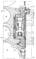
- a spar 1 of a stand of a hot rolling stand has broken off shown, with a bending device shown as a vertical section 2 is provided.
- the essential components of this bending device 2 are in a hollow cylindrical housing 3 is arranged.
- a vertically movable Printing cylinder 4 contains in its upper, expanded, and guided in the housing 3 Area a piston 5, the piston rod 6 in the lower, also with smaller outer diameter executed area of the pressure cylinder 4 in a stamp sleeve 7 is guided, which in turn through wear surfaces 8th of the housing 3 is guided.
- the piston rod 6 passes through a flange Stamp sleeve 7 and is supported on this by means of a pressure ring 9, while the end sleeve 11 held with an end plate 10 tensile forces of the piston rod 6 is able to transfer.
- the end plate 10 is with a lateral one Provide recess of the stamp sleeve 7 engaging nose, which together with a bolt connected to it as an anti-rotation device for pistons 5 and Piston rod 6 is used.
- the work rolls 16, 17 of the hot rolling stand designed as a four-high stand are stored in the chocks 18, 19 with bearings, not shown.
- These chocks are equipped with laterally projecting lugs 20, 21, which engage in grooves 22, 23 of the guide pieces 12, 13 and via pressure plates 24 support themselves against their flanks.
- the nose 21 is with another Pressure plate 25 equipped, on which the complete set of work rolls Switch is extendable.
- the lug 20 of the chock 18 holds the guide piece 12 at a height assigned to the work roll 16 via its pressure plates 24 which are supported on the flanks of the groove 22, while the position of the work roll 17 over the lug 21 and the flanks of the groove 23 supporting pressure plates 24 determines the height of the guide piece 13.
- the punch sleeve 7 and the piston rod 6 of the piston 5 are connected to the guide piece 13, while the guide piece 12 is screwed to the pressure cylinder 4. This means that the position of the piston 5 in the pressure cylinder 4 is determined by the position of the chocks 18 and 19.
- the upper and / or the lower of the cylinder chambers formed in the pressure cylinder 4 are now pressurized and the surfaces of the double-acting piston 5 are accordingly acted upon.
- the forces thus developed on the piston surfaces are supplied to the guide pieces 12, 13 which can be displaced vertically by the guide surfaces of the pressure cylinder 4 and the stamp sleeve 7 in the housing 3 and, via the lugs 20, 21, stress the chocks 18, 19 with the required pretension.
- the work rolls 16, 17 are moved by the lifting rail 28 raised, the lower chock 19 with its on the nose 21st provided pressure plate 25 is supported on the lifting rail 28.
- the bending device For the roll change, it is expedient and known to use parts of the bending device to fix in their intended position for the roll change in order after the roller has been extended, it can be adjusted again without further adjustment to be able to drive in.
- the piston 30 In the exemplary embodiment, there is one in a recess of the spar 1 arranged hydraulic cylinder 29 is provided, the piston 30 is equipped with a centering pin 31. In the drawing this is Bolt shown in the locking position in which the piston 30 is pushed out and the bolt 31 in a recess of the guide piece 12, keeping it at a constant height, inserted.
Landscapes
- Engineering & Computer Science (AREA)
- Mechanical Engineering (AREA)
- Bending Of Plates, Rods, And Pipes (AREA)
- Metal Rolling (AREA)
- Shaping Of Tube Ends By Bending Or Straightening (AREA)
- Actuator (AREA)
Applications Claiming Priority (3)
| Application Number | Priority Date | Filing Date | Title |
|---|---|---|---|
| DE19922373A DE19922373A1 (de) | 1999-05-14 | 1999-05-14 | Biegevorrichtung für die Arbeitswalzen eines Warmwalzgerüstes |
| DE19922373 | 1999-05-14 | ||
| PCT/EP2000/004075 WO2000069579A1 (de) | 1999-05-14 | 2000-05-06 | Biegevorrichtung für die arbeitswalzen eines warmwalzgerüstes |
Publications (2)
| Publication Number | Publication Date |
|---|---|
| EP1181114A1 EP1181114A1 (de) | 2002-02-27 |
| EP1181114B1 true EP1181114B1 (de) | 2003-03-05 |
Family
ID=7908151
Family Applications (1)
| Application Number | Title | Priority Date | Filing Date |
|---|---|---|---|
| EP00927155A Expired - Lifetime EP1181114B1 (de) | 1999-05-14 | 2000-05-06 | Biegevorrichtung für die arbeitswalzen eines warmwalzgerüstes |
Country Status (14)
Cited By (1)
| Publication number | Priority date | Publication date | Assignee | Title |
|---|---|---|---|---|
| DE10333883B3 (de) * | 2003-07-25 | 2004-10-07 | ACHENBACH BUSCHHüTTEN GMBH | Biegevorrichtung für die Walzen eines Mehrwalzengerüstes |
Families Citing this family (11)
| Publication number | Priority date | Publication date | Assignee | Title |
|---|---|---|---|---|
| TW501954B (en) * | 2000-06-30 | 2002-09-11 | Sms Demag Ag | Roll stand, especially a duo or quarto roll stand, comprising bending and balancing devices for axially displaceable rollers |
| DE10334682A1 (de) * | 2003-07-30 | 2005-02-17 | Sms Demag Ag | Walzvorrichtung |
| CN1320968C (zh) * | 2005-04-29 | 2007-06-13 | 中国第二重型机械集团公司 | 轧机弯辊串辊装置 |
| EP1772203A1 (en) * | 2005-10-10 | 2007-04-11 | VAI Industries (UK) Limited | Roll bending device |
| AT504208B1 (de) * | 2006-04-21 | 2008-04-15 | Siemens Vai Metals Tech Gmbh | Biegevorrichtung für zwei arbeitswalzen eines walzgerüstes |
| DE102007001322A1 (de) * | 2007-01-03 | 2008-07-10 | Sms Demag Ag | Führungsvorrichtung für die Einbaustücke von Arbeitswalzen |
| DE102009058876A1 (de) † | 2009-01-23 | 2010-07-29 | Sms Siemag Ag | Biege- und Ausbalanciervorrichtung für axial verschiebbare Arbeitswalzen eines Walzgerüstes |
| ITMI20101502A1 (it) * | 2010-08-05 | 2012-02-06 | Danieli Off Mecc | Sistema integrato di bending e shifting sotto carico per gabbie ad elevata apertura tra i rulli di lavoro |
| WO2012049183A1 (de) | 2010-10-12 | 2012-04-19 | Sms Siemag Ag | Walzgerüst |
| CN104226690B (zh) * | 2014-09-30 | 2017-07-28 | 中色科技股份有限公司 | 一种弯辊装置 |
| CN106670236B (zh) * | 2017-03-21 | 2018-07-13 | 北京京诚之星科技开发有限公司 | 板带轧机双重导向工作辊弯辊及平衡装置 |
Family Cites Families (14)
| Publication number | Priority date | Publication date | Assignee | Title |
|---|---|---|---|---|
| US2430410A (en) * | 1943-03-27 | 1947-11-04 | Carnegie Illinois Steel Corp | Working pass control for rolling mills |
| DE3261730D1 (en) * | 1981-02-28 | 1985-02-14 | Schloemann Siemag Ag | Roll stand |
| JPS59153505A (ja) | 1983-02-22 | 1984-09-01 | Ishikawajima Harima Heavy Ind Co Ltd | 圧延機 |
| JPS59185505A (ja) | 1983-04-05 | 1984-10-22 | Ishikawajima Harima Heavy Ind Co Ltd | 圧延機 |
| DE3331055C2 (de) * | 1983-08-29 | 1994-11-03 | Schloemann Siemag Ag | Walzgerüst mit axial verschieblichen Arbeitswalzen |
| DE3503756A1 (de) * | 1984-03-13 | 1985-09-19 | SMS Schloemann-Siemag AG, 4000 Düsseldorf | Sechswalzengeruest |
| JPS6152914A (ja) | 1984-08-24 | 1986-03-15 | Ishikawajima Harima Heavy Ind Co Ltd | 圧延機 |
| DE3529363A1 (de) * | 1985-08-16 | 1987-02-19 | Schloemann Siemag Ag | Anstellvorrichtung fuer das achsparallele verschieben von walzen eines walzgeruestes |
| DE3638330A1 (de) * | 1986-11-10 | 1988-05-19 | Schloemann Siemag Ag | Walzgeruest mit einer vorrichtung zum axialen verschieben von anstellbaren walzen |
| DE3728795A1 (de) | 1987-08-26 | 1989-03-09 | Mannesmann Ag | Walzgeruest mit arbeitswalzen |
| DE3843387A1 (de) * | 1988-12-23 | 1990-07-05 | Schloemann Siemag Ag | Vorrichtung zum walzenwechsel insbesondere der horizontal verschieblichen arbeitswalzen in einem walzgeruest |
| DE4308743C2 (de) | 1993-03-19 | 2003-03-20 | Sms Demag Ag | Walzgerüst |
| DE4314472A1 (de) * | 1993-05-03 | 1994-11-10 | Schloemann Siemag Ag | Biegeblock zum Biegen der Walzen von Mehrwalzen-Walzgerüsten |
| DE19536042A1 (de) | 1995-09-28 | 1997-04-03 | Schloemann Siemag Ag | Führungsvorrichtung für Vier- oder Mehrwalzengerüste |
-
1999
- 1999-05-14 DE DE19922373A patent/DE19922373A1/de not_active Withdrawn
-
2000
- 2000-05-06 US US09/979,949 patent/US6993951B1/en not_active Expired - Fee Related
- 2000-05-06 BR BR0010578-3A patent/BR0010578A/pt not_active IP Right Cessation
- 2000-05-06 DE DE50001393T patent/DE50001393D1/de not_active Expired - Lifetime
- 2000-05-06 AT AT00927155T patent/ATE233614T1/de active
- 2000-05-06 ES ES00927155T patent/ES2193955T3/es not_active Expired - Lifetime
- 2000-05-06 MX MXPA01011655A patent/MXPA01011655A/es active IP Right Grant
- 2000-05-06 CA CA002373260A patent/CA2373260C/en not_active Expired - Fee Related
- 2000-05-06 EA EA200101202A patent/EA003224B1/ru not_active IP Right Cessation
- 2000-05-06 KR KR1020017014128A patent/KR100626609B1/ko not_active Expired - Fee Related
- 2000-05-06 JP JP2000618030A patent/JP5170920B2/ja not_active Expired - Fee Related
- 2000-05-06 WO PCT/EP2000/004075 patent/WO2000069579A1/de active IP Right Grant
- 2000-05-06 EP EP00927155A patent/EP1181114B1/de not_active Expired - Lifetime
- 2000-05-06 CN CNB008075786A patent/CN1142834C/zh not_active Expired - Fee Related
- 2000-05-06 AU AU45626/00A patent/AU4562600A/en not_active Abandoned
Cited By (2)
| Publication number | Priority date | Publication date | Assignee | Title |
|---|---|---|---|---|
| DE10333883B3 (de) * | 2003-07-25 | 2004-10-07 | ACHENBACH BUSCHHüTTEN GMBH | Biegevorrichtung für die Walzen eines Mehrwalzengerüstes |
| EP1500442A1 (de) * | 2003-07-25 | 2005-01-26 | ACHENBACH BUSCHHÜTTEN GmbH | Biegevorrichtung für die Walzen eines Mehrwalzengerüstes |
Also Published As
| Publication number | Publication date |
|---|---|
| DE19922373A1 (de) | 2000-11-16 |
| AU4562600A (en) | 2000-12-05 |
| US6993951B1 (en) | 2006-02-07 |
| ATE233614T1 (de) | 2003-03-15 |
| BR0010578A (pt) | 2002-02-19 |
| EA003224B1 (ru) | 2003-02-27 |
| CA2373260A1 (en) | 2000-11-23 |
| CN1350480A (zh) | 2002-05-22 |
| WO2000069579A8 (de) | 2003-12-11 |
| DE50001393D1 (de) | 2003-04-10 |
| JP2002543986A (ja) | 2002-12-24 |
| CN1142834C (zh) | 2004-03-24 |
| MXPA01011655A (es) | 2004-09-10 |
| EA200101202A1 (ru) | 2002-08-29 |
| EP1181114A1 (de) | 2002-02-27 |
| ES2193955T3 (es) | 2003-11-16 |
| WO2000069579A1 (de) | 2000-11-23 |
| KR100626609B1 (ko) | 2006-09-22 |
| JP5170920B2 (ja) | 2013-03-27 |
| KR20020000884A (ko) | 2002-01-05 |
| CA2373260C (en) | 2007-04-24 |
Similar Documents
| Publication | Publication Date | Title |
|---|---|---|
| EP0235332B1 (de) | Walzgerüst | |
| EP1181114B1 (de) | Biegevorrichtung für die arbeitswalzen eines warmwalzgerüstes | |
| EP1318879B1 (de) | Kombinierter antrieb für ein vierwalzen- bzw. sechswalzengerüst sowie betriebsverfahren hierfür | |
| EP0340504B1 (de) | Biege- und Ausbalanciervorrichtung für axial verschiebbare Walzen eines Walzgerüstes | |
| DE3638330A1 (de) | Walzgeruest mit einer vorrichtung zum axialen verschieben von anstellbaren walzen | |
| EP2451592A1 (de) | 4-rollen-/ 6-rollen/ 18hs rollenwalzgerüst in kassettenbauweise | |
| EP0154896B1 (de) | Sechswalzengerüst | |
| DE2654768C2 (de) | Walzenwechselvorrichtung | |
| DE10116988B4 (de) | Walzgerüst | |
| DE3335857A1 (de) | Walzgeruest mit mittels stuetzrollen abstuetzbarer arbeitswalzen | |
| DE1954460C3 (de) | Abstandshalteeinrichtung an einem Walzgerüst mit auswechselbaren Abstandswalzen | |
| DE1965337A1 (de) | Verbesserungen an einem Walzwerk | |
| EP0256408A2 (de) | Biege- und Ausbalanciervorrichtung für axial verschiebbare Arbeitswalzen eines Quartowalzgerüstes | |
| EP0256410A2 (de) | Biege- und Ausbalanciervorrichtung für axial verschiebbare Arbeitswalzen eines Quartowalzgerüstes | |
| DE2514898C3 (de) | Vorrichtung zum Aufweiten großer Ringe | |
| DE1940414B2 (de) | Walzgerüst mit einer Einrichtung zum Walzenwechsel | |
| EP0354170B1 (de) | Vorrichtung zur Axialführung der Walzen von Walzgerüsten | |
| AT390741B (de) | Walzwerk, insbesondere kaltwalzwerk | |
| DE950455C (de) | Ein Ausweichen der Einbaustuecke in axialer Richtung ermoeglichende Vorrichtung zum axialen Festlegen der Walzen von Walzgeruesten in ihren Staendern | |
| DE2138894A1 (de) | Walzgeruest mit arbeits- und stuetzwalzen, insbesondere quartowalzgeruest zum walzen von grobblechen | |
| DE19717914C2 (de) | Vorrichtung zum Ausziehen eines Stranges | |
| DE2245831C3 (de) | Walzgerüst für ein Blechwalzwerk | |
| DE3807628C2 (de) | Walzgerüst mit Verschiebeeinrichtung | |
| DE1936769A1 (de) | Vorrichtung zur Balligkeitssteuerung der Arbeitswalzen in einem Duo-Metallwalzwerk | |
| EP1500442B1 (de) | Biegevorrichtung für die Walzen eines Mehrwalzengerüstes |
Legal Events
| Date | Code | Title | Description |
|---|---|---|---|
| PUAI | Public reference made under article 153(3) epc to a published international application that has entered the european phase |
Free format text: ORIGINAL CODE: 0009012 |
|
| 17P | Request for examination filed |
Effective date: 20011023 |
|
| AK | Designated contracting states |
Kind code of ref document: A1 Designated state(s): AT BE CH CY DE DK ES FI FR GB GR IE IT LI LU MC NL PT SE |
|
| AX | Request for extension of the european patent |
Free format text: AL;LT;LV;MK;RO;SI |
|
| 17Q | First examination report despatched |
Effective date: 20020327 |
|
| GRAH | Despatch of communication of intention to grant a patent |
Free format text: ORIGINAL CODE: EPIDOS IGRA |
|
| GRAH | Despatch of communication of intention to grant a patent |
Free format text: ORIGINAL CODE: EPIDOS IGRA |
|
| GRAA | (expected) grant |
Free format text: ORIGINAL CODE: 0009210 |
|
| AK | Designated contracting states |
Designated state(s): AT BE CH CY DE DK ES FI FR GB GR IE IT LI LU MC NL PT SE |
|
| PG25 | Lapsed in a contracting state [announced via postgrant information from national office to epo] |
Ref country code: IE Free format text: LAPSE BECAUSE OF FAILURE TO SUBMIT A TRANSLATION OF THE DESCRIPTION OR TO PAY THE FEE WITHIN THE PRESCRIBED TIME-LIMIT Effective date: 20030305 Ref country code: GR Free format text: LAPSE BECAUSE OF FAILURE TO SUBMIT A TRANSLATION OF THE DESCRIPTION OR TO PAY THE FEE WITHIN THE PRESCRIBED TIME-LIMIT Effective date: 20030305 |
|
| REG | Reference to a national code |
Ref country code: GB Ref legal event code: FG4D Free format text: NOT ENGLISH |
|
| REG | Reference to a national code |
Ref country code: CH Ref legal event code: EP |
|
| REG | Reference to a national code |
Ref country code: IE Ref legal event code: FG4D Free format text: GERMAN |
|
| REF | Corresponds to: |
Ref document number: 50001393 Country of ref document: DE Date of ref document: 20030410 Kind code of ref document: P |
|
| PG25 | Lapsed in a contracting state [announced via postgrant information from national office to epo] |
Ref country code: CY Free format text: LAPSE BECAUSE OF FAILURE TO SUBMIT A TRANSLATION OF THE DESCRIPTION OR TO PAY THE FEE WITHIN THE PRESCRIBED TIME-LIMIT Effective date: 20030506 Ref country code: LU Free format text: LAPSE BECAUSE OF NON-PAYMENT OF DUE FEES Effective date: 20030506 |
|
| PG25 | Lapsed in a contracting state [announced via postgrant information from national office to epo] |
Ref country code: MC Free format text: LAPSE BECAUSE OF NON-PAYMENT OF DUE FEES Effective date: 20030531 |
|
| PG25 | Lapsed in a contracting state [announced via postgrant information from national office to epo] |
Ref country code: DK Free format text: LAPSE BECAUSE OF FAILURE TO SUBMIT A TRANSLATION OF THE DESCRIPTION OR TO PAY THE FEE WITHIN THE PRESCRIBED TIME-LIMIT Effective date: 20030605 |
|
| PG25 | Lapsed in a contracting state [announced via postgrant information from national office to epo] |
Ref country code: PT Free format text: LAPSE BECAUSE OF FAILURE TO SUBMIT A TRANSLATION OF THE DESCRIPTION OR TO PAY THE FEE WITHIN THE PRESCRIBED TIME-LIMIT Effective date: 20030606 |
|
| RIN2 | Information on inventor provided after grant (corrected) |
Inventor name: DIE ANDERE ERFINDER HABEN AUF IHRE NENNUNG VERZICH Inventor name: MUELLER, HEINZ-ADOLF Inventor name: SUDAU, PETER |
|
| GBT | Gb: translation of ep patent filed (gb section 77(6)(a)/1977) | ||
| LTIE | Lt: invalidation of european patent or patent extension |
Effective date: 20030305 |
|
| ET | Fr: translation filed | ||
| REG | Reference to a national code |
Ref country code: IE Ref legal event code: FD4D Ref document number: 1181114E Country of ref document: IE |
|
| REG | Reference to a national code |
Ref country code: ES Ref legal event code: FG2A Ref document number: 2193955 Country of ref document: ES Kind code of ref document: T3 |
|
| PLBE | No opposition filed within time limit |
Free format text: ORIGINAL CODE: 0009261 |
|
| STAA | Information on the status of an ep patent application or granted ep patent |
Free format text: STATUS: NO OPPOSITION FILED WITHIN TIME LIMIT |
|
| 26N | No opposition filed |
Effective date: 20031208 |
|
| PG25 | Lapsed in a contracting state [announced via postgrant information from national office to epo] |
Ref country code: CH Free format text: LAPSE BECAUSE OF NON-PAYMENT OF DUE FEES Effective date: 20040531 Ref country code: LI Free format text: LAPSE BECAUSE OF NON-PAYMENT OF DUE FEES Effective date: 20040531 |
|
| REG | Reference to a national code |
Ref country code: CH Ref legal event code: PL |
|
| PGFP | Annual fee paid to national office [announced via postgrant information from national office to epo] |
Ref country code: NL Payment date: 20140521 Year of fee payment: 15 Ref country code: FI Payment date: 20140513 Year of fee payment: 15 Ref country code: FR Payment date: 20140527 Year of fee payment: 15 Ref country code: SE Payment date: 20140520 Year of fee payment: 15 Ref country code: ES Payment date: 20140528 Year of fee payment: 15 |
|
| PGFP | Annual fee paid to national office [announced via postgrant information from national office to epo] |
Ref country code: BE Payment date: 20140523 Year of fee payment: 15 |
|
| REG | Reference to a national code |
Ref country code: DE Ref legal event code: R082 Ref document number: 50001393 Country of ref document: DE Representative=s name: HEMMERICH & KOLLEGEN, DE Ref country code: DE Ref legal event code: R081 Ref document number: 50001393 Country of ref document: DE Owner name: SMS GROUP GMBH, DE Free format text: FORMER OWNER: SMS SIEMAG AKTIENGESELLSCHAFT, 40237 DUESSELDORF, DE |
|
| PG25 | Lapsed in a contracting state [announced via postgrant information from national office to epo] |
Ref country code: FI Free format text: LAPSE BECAUSE OF NON-PAYMENT OF DUE FEES Effective date: 20150506 |
|
| REG | Reference to a national code |
Ref country code: NL Ref legal event code: MM Effective date: 20150601 |
|
| REG | Reference to a national code |
Ref country code: FR Ref legal event code: ST Effective date: 20160129 |
|
| PG25 | Lapsed in a contracting state [announced via postgrant information from national office to epo] |
Ref country code: SE Free format text: LAPSE BECAUSE OF NON-PAYMENT OF DUE FEES Effective date: 20150507 |
|
| PG25 | Lapsed in a contracting state [announced via postgrant information from national office to epo] |
Ref country code: NL Free format text: LAPSE BECAUSE OF NON-PAYMENT OF DUE FEES Effective date: 20150601 |
|
| PG25 | Lapsed in a contracting state [announced via postgrant information from national office to epo] |
Ref country code: FR Free format text: LAPSE BECAUSE OF NON-PAYMENT OF DUE FEES Effective date: 20150601 |
|
| REG | Reference to a national code |
Ref country code: ES Ref legal event code: FD2A Effective date: 20160630 |
|
| PG25 | Lapsed in a contracting state [announced via postgrant information from national office to epo] |
Ref country code: ES Free format text: LAPSE BECAUSE OF NON-PAYMENT OF DUE FEES Effective date: 20150507 |
|
| PGFP | Annual fee paid to national office [announced via postgrant information from national office to epo] |
Ref country code: DE Payment date: 20160520 Year of fee payment: 17 Ref country code: GB Payment date: 20160520 Year of fee payment: 17 |
|
| PGFP | Annual fee paid to national office [announced via postgrant information from national office to epo] |
Ref country code: AT Payment date: 20160520 Year of fee payment: 17 Ref country code: IT Payment date: 20160524 Year of fee payment: 17 |
|
| PG25 | Lapsed in a contracting state [announced via postgrant information from national office to epo] |
Ref country code: BE Free format text: LAPSE BECAUSE OF NON-PAYMENT OF DUE FEES Effective date: 20150531 |
|
| REG | Reference to a national code |
Ref country code: DE Ref legal event code: R119 Ref document number: 50001393 Country of ref document: DE |
|
| REG | Reference to a national code |
Ref country code: AT Ref legal event code: MM01 Ref document number: 233614 Country of ref document: AT Kind code of ref document: T Effective date: 20170506 |
|
| GBPC | Gb: european patent ceased through non-payment of renewal fee |
Effective date: 20170506 |
|
| PG25 | Lapsed in a contracting state [announced via postgrant information from national office to epo] |
Ref country code: AT Free format text: LAPSE BECAUSE OF NON-PAYMENT OF DUE FEES Effective date: 20170506 |
|
| PG25 | Lapsed in a contracting state [announced via postgrant information from national office to epo] |
Ref country code: GB Free format text: LAPSE BECAUSE OF NON-PAYMENT OF DUE FEES Effective date: 20170506 Ref country code: DE Free format text: LAPSE BECAUSE OF NON-PAYMENT OF DUE FEES Effective date: 20171201 |
|
| PG25 | Lapsed in a contracting state [announced via postgrant information from national office to epo] |
Ref country code: IT Free format text: LAPSE BECAUSE OF NON-PAYMENT OF DUE FEES Effective date: 20170506 |