EP1180645B1 - Method of manufacturing a sheathed glow plug - Google Patents
Method of manufacturing a sheathed glow plug Download PDFInfo
- Publication number
- EP1180645B1 EP1180645B1 EP01906355A EP01906355A EP1180645B1 EP 1180645 B1 EP1180645 B1 EP 1180645B1 EP 01906355 A EP01906355 A EP 01906355A EP 01906355 A EP01906355 A EP 01906355A EP 1180645 B1 EP1180645 B1 EP 1180645B1
- Authority
- EP
- European Patent Office
- Prior art keywords
- diameter
- axial
- axial shaft
- manufacturing
- center electrode
- Prior art date
- Legal status (The legal status is an assumption and is not a legal conclusion. Google has not performed a legal analysis and makes no representation as to the accuracy of the status listed.)
- Expired - Lifetime
Links
- 238000004519 manufacturing process Methods 0.000 title claims description 19
- 229910052751 metal Inorganic materials 0.000 claims description 32
- 239000002184 metal Substances 0.000 claims description 32
- 238000003466 welding Methods 0.000 claims description 27
- 238000000034 method Methods 0.000 claims description 13
- XKRFYHLGVUSROY-UHFFFAOYSA-N Argon Chemical compound [Ar] XKRFYHLGVUSROY-UHFFFAOYSA-N 0.000 claims description 11
- 229910052786 argon Inorganic materials 0.000 claims description 6
- 238000010438 heat treatment Methods 0.000 description 8
- 238000009413 insulation Methods 0.000 description 8
- 239000000843 powder Substances 0.000 description 5
- 239000000155 melt Substances 0.000 description 4
- 238000002485 combustion reaction Methods 0.000 description 3
- CPLXHLVBOLITMK-UHFFFAOYSA-N Magnesium oxide Chemical compound [Mg]=O CPLXHLVBOLITMK-UHFFFAOYSA-N 0.000 description 2
- PXHVJJICTQNCMI-UHFFFAOYSA-N Nickel Chemical compound [Ni] PXHVJJICTQNCMI-UHFFFAOYSA-N 0.000 description 2
- 239000012300 argon atmosphere Substances 0.000 description 2
- 230000002542 deteriorative effect Effects 0.000 description 2
- 238000012856 packing Methods 0.000 description 2
- 229910001209 Low-carbon steel Inorganic materials 0.000 description 1
- 150000001485 argon Chemical class 0.000 description 1
- 239000000919 ceramic Substances 0.000 description 1
- UPHIPHFJVNKLMR-UHFFFAOYSA-N chromium iron Chemical compound [Cr].[Fe] UPHIPHFJVNKLMR-UHFFFAOYSA-N 0.000 description 1
- 230000005347 demagnetization Effects 0.000 description 1
- 238000002347 injection Methods 0.000 description 1
- 239000007924 injection Substances 0.000 description 1
- 239000007788 liquid Substances 0.000 description 1
- 239000000395 magnesium oxide Substances 0.000 description 1
- 238000002844 melting Methods 0.000 description 1
- 230000008018 melting Effects 0.000 description 1
- 229910052759 nickel Inorganic materials 0.000 description 1
- 238000007747 plating Methods 0.000 description 1
- 239000010935 stainless steel Substances 0.000 description 1
- 229910001220 stainless steel Inorganic materials 0.000 description 1
Images


Classifications
-
- H—ELECTRICITY
- H05—ELECTRIC TECHNIQUES NOT OTHERWISE PROVIDED FOR
- H05B—ELECTRIC HEATING; ELECTRIC LIGHT SOURCES NOT OTHERWISE PROVIDED FOR; CIRCUIT ARRANGEMENTS FOR ELECTRIC LIGHT SOURCES, IN GENERAL
- H05B3/00—Ohmic-resistance heating
- H05B3/10—Heating elements characterised by the composition or nature of the materials or by the arrangement of the conductor
- H05B3/12—Heating elements characterised by the composition or nature of the materials or by the arrangement of the conductor characterised by the composition or nature of the conductive material
- H05B3/14—Heating elements characterised by the composition or nature of the materials or by the arrangement of the conductor characterised by the composition or nature of the conductive material the material being non-metallic
- H05B3/141—Conductive ceramics, e.g. metal oxides, metal carbides, barium titanate, ferrites, zirconia, vitrous compounds
-
- F—MECHANICAL ENGINEERING; LIGHTING; HEATING; WEAPONS; BLASTING
- F23—COMBUSTION APPARATUS; COMBUSTION PROCESSES
- F23Q—IGNITION; EXTINGUISHING-DEVICES
- F23Q7/00—Incandescent ignition; Igniters using electrically-produced heat, e.g. lighters for cigarettes; Electrically-heated glowing plugs
- F23Q7/001—Glowing plugs for internal-combustion engines
-
- H—ELECTRICITY
- H05—ELECTRIC TECHNIQUES NOT OTHERWISE PROVIDED FOR
- H05B—ELECTRIC HEATING; ELECTRIC LIGHT SOURCES NOT OTHERWISE PROVIDED FOR; CIRCUIT ARRANGEMENTS FOR ELECTRIC LIGHT SOURCES, IN GENERAL
- H05B3/00—Ohmic-resistance heating
- H05B3/02—Details
- H05B3/03—Electrodes
-
- H—ELECTRICITY
- H05—ELECTRIC TECHNIQUES NOT OTHERWISE PROVIDED FOR
- H05B—ELECTRIC HEATING; ELECTRIC LIGHT SOURCES NOT OTHERWISE PROVIDED FOR; CIRCUIT ARRANGEMENTS FOR ELECTRIC LIGHT SOURCES, IN GENERAL
- H05B3/00—Ohmic-resistance heating
- H05B3/40—Heating elements having the shape of rods or tubes
- H05B3/42—Heating elements having the shape of rods or tubes non-flexible
- H05B3/48—Heating elements having the shape of rods or tubes non-flexible heating conductor embedded in insulating material
-
- F—MECHANICAL ENGINEERING; LIGHTING; HEATING; WEAPONS; BLASTING
- F23—COMBUSTION APPARATUS; COMBUSTION PROCESSES
- F23Q—IGNITION; EXTINGUISHING-DEVICES
- F23Q7/00—Incandescent ignition; Igniters using electrically-produced heat, e.g. lighters for cigarettes; Electrically-heated glowing plugs
- F23Q7/001—Glowing plugs for internal-combustion engines
- F23Q2007/004—Manufacturing or assembling methods
-
- H—ELECTRICITY
- H05—ELECTRIC TECHNIQUES NOT OTHERWISE PROVIDED FOR
- H05B—ELECTRIC HEATING; ELECTRIC LIGHT SOURCES NOT OTHERWISE PROVIDED FOR; CIRCUIT ARRANGEMENTS FOR ELECTRIC LIGHT SOURCES, IN GENERAL
- H05B2203/00—Aspects relating to Ohmic resistive heating covered by group H05B3/00
- H05B2203/027—Heaters specially adapted for glow plug igniters
Definitions
- the present invention relates to a method of manufacturing a sheathed glow plug used in starting aids for internal combustion engines such as diesel engine, and in sheathed heater, liquid heating devices and the like,
- a sheathed glow plug comprising a cylindrical main metal shell, a heat resisting tube mounted in a leading end of a through hole of the main metal shell, a center electrode disposed in a center portion of the through hole of the main metal shell and an electric heat generator electrically connected to the center electrode, which is accommodated in the heat resisting tube and disposed between the center electrode and the heat resisting tube, wherein the center electrode is composed by coaxially welding a leading end axial shaft and a rear end axial shaft.
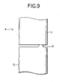
- a center electrode (a) used in the sheathed glow plug is formed by welding a leading end axial shaft (b) and a rear end axial shaft (c) whose connecting end's diameter is the same as that of the former axial shaft such that their connecting ends are mutually coaxial.
- a coaxial property between both axial shafts is deteriorated.
- a molten metal flows to this portion and thus a deviation of bonded state in a face direction occurs and, thereby, such a case occurs that a regular face-connecting is not performed and this becomes a cause of an eccentricity as well.
- a molten metal protrudes in a periphery of that connecting portion to form a burr (x) (refer to Fig.10 ). If the burr(x)is left as it is, since the burr (x) contacts with an inner face of a main metal shell to generate an electric short-circuit, it is necessary to remove the burr by means such as a grinder. By the way, hitherto, a maximum size of the burr becomes larger in its diameter than the axial shaft.
- An object of the invention is to solve the problems of such a conventional constitution.
- JP-4-024420 which is considered to represent the closest prior art, discloses a method of manufacturing the center electrode of a sheathed glow plug according to the pre-characterizing portion of claim 1.
- the invention is a method of manufacturing a sheathed glow plug, the glow plug comprising: a cylindrical main metal shell; a heat resisting tube mounted to a leading end of a through hole of the main metal shell; a center electrode, that comprises a leading end axial shaft and a rear end axial shaft coaxially to welded to each other, disposed in a center portion of the through hole of the main metal shell; and an electric heat generator received in the heat resisting tube, the electric heat generator having one end electrically connected to the center electrode, said method comprising a process of manufacturing the center electrode comprising the steps of: disposing the leading end axial shaft and the rear end axial shaft on the same axis; bringing the connecting ends of said axial shafts into contact; characterized by the steps of:
- the butting face between the connecting ends becomes a small area depending on the diameter of the connecting end having a smaller diameter and, after such a butting face has been preferentially molten, the other portion is welded. Therefore, even if a connecting end face has an error of right angle degree or becomes a rough face, its influence can be suppressed because the diameter of the butting face is small, so that the resistance welding can be stably performed. Further, even if a burr is generated in a periphery edge of the connecting face by the resistance welding, a burr generation amount becomes small because an area of the butting face is small. And, so long as the burr does not protrude the main diameter of the axial shaft having a larger diameter, it becomes an allowable range, so that a burr removable can be omitted or a simple burr removal work suffices.
- the process of manufacturing the center electrode further comprises a step of making the diameter of the connecting end of the one of the axial shafts smaller than the main diameter of said one of the axial shafts, wherein said main diameter is the substantially uniform diameter of said one axial shaft along its length away from its connecting end.
- the diameter of the connecting end having a small diameter prescribing the butting face can be made as small as possible without making the diameters of both axial shafts small so much. Therefore, it is possible to regularly bond the axial shafts together without reducing a strength of the center electrode to improve a coaxial degree. Further, since the diameter of the butting face is small, the maximum size of the burr becomes small as well, so that the burr removal becomes easy or unnecessary.
- the process of manufacturing the center electrode further comprises a step of forming the connecting end of the one of the axial shafts at a connecting side of said one of the axial shafts by forming a different diameter protrusion portion whose diameter is smaller than the main diameter of said one of the axial shafts, wherein said main diameter is the substantially uniform diameter of said one axial shaft along its length away from its connecting end.
- the process of manufacturing the center electrode further comprises a step of forming the connecting end of the one of the axial shafts at a connecting side of said one of the axial shafts by forming a tapering truncated cone portion.
- burr removal means in order to remove the burr, it is possible to remove the burr generated in a connecting portion periphery edge by more than two points argon arc welding.
- the burr removal can be performed simply and without deteriorating the welding strength in comparison with a case where the burr removal is performed by a grinder.
- 1 indicates sheathed glow plug
- 2 indicates main metal shell
- 4 indicates center electrode
- 5 and 6 indicate axial shaft
- 11 indicates heating coil (electric heat generator)
- 10 indicates heat resisting tube
- 30a indicates small diameter portion
- 30b indicates truncated cone portion.
- sheathed glow plug 1 having a center electrode 4 according to the invention is explained on the basis of Fig. 1 .
- the sheathed glow plug 1 is composed by a cylindrical main metal shell 2 formed with a screw mounted on an engine, a metal made heat resisting tube 10 mounted on a leading end of the main metal shell 2, a center electrode 4 disposed in a center portion of the main metal shell 2, a heating coil (electric heat generator) 11 accommodated in the heat resisting tube 10, an insulation powder 12 filled in the heat resisting tube 10 under a state that the heating coil 11 and a leading end of the center electrode 4 are accommodated therein, and the like.
- the main metal shell 2 is formed of a low carbon steel, and on its outer wall there is applied a metal plating as occasion demands.
- the heat resisting tube 10 is formed, for example, of a. heat resisting stainless steel, its rear end side is pressure-inserted into the main metal shell 2, and its leading end is exposed to a combustion chamber (not shown) of diesel engine.
- the center electrode 4 is disposed coaxially with the main metal shell 2, and electrically insulated by securing a periphery gap with respect to the through hole 3 of the main metal shell 2.
- the center electrode 4 is composed of a leading end axial shaft 5 of 2.7 to 3.6 mm in its outer diameter and a rear end axial shaft 6 of 3.2 to 5.0 mm in its main diameter.
- a shape of a connecting end portion of each of the axial shafts 5 and 6 constitutes an important part of the invention, and the center electrode 4 is formed by means of mutually connecting the connecting ends in an axial direction by a resistance welding. Further, a screw portion 7 is formed in a rear end portion of the rear end axial shaft 6.
- an upper end of the through hole 3 is enlarged in its diameter, an insulation plug 17 outwardly fitted to the center electrode 4 is mounted on an upper end of the main metal shell 2 through an O-ring 16, and a terminal nut 18 is screwed to the screw portion 7.
- the heating coil 11 there are used, for example, an iron chromium based wire rod and a nickel based wire rod, one end thereof (upper end in Fig.1 ) is connected to a leading end of the center electrode 4, and the other end thereof is connected to a bottom portion of the heat resisting tube. 10. Further, for the insulation powder 12 in the heat resisting tube 10, there is used a ceramics powder having an electric insulation property such as magnesia. Additionally, to.a rear end opening portion of the heat resisting tube 10, the insulation powder is filled and thereafter, a packing 13 having an insulation property is fitted.
- a sheathed heater portion 15 is assembled. As to the sheathed heater portion 15, one end of the heating coil 11 is welded to the leading end axial shaft 5 of the center electrode 4, thereafter the heating coil 11 is inserted into the heat resisting tube 10, and the other end of the heating coil 11 is welded to a bottom portion of the heat resisting tube 10. Thereafter, the insulation powder 12 is filled in the heat resisting tube 10, and the packing 13 is mounted to the opening portion of the heat resisting tube 10, thereby completing an assembly.
- the leading end axial shaft 5 and the rear end axial shaft 6 are held by the electrodes 19, 20 under a state that the leading end axial shaft 5 and the rear end axial shaft 6 are butted in an axial direction. And, in an argon atmosphere, an electric current is applied between the electrodes 19, 20, and the connecting end of the leading end axial shaft 5 and the connecting end of the rear end axial shaft 6 are mutually resistance-welded. In the resistance welding in order to obtain a sufficient strength of the connecting portion, it follows that the connecting portion is molten until a weld burr protrudes from an outer diameter of the center electrode 4.
- the connecting portions of the leading end axial shaft 5 and the rear end axial shaft 6 are prescribed to a predetermined shape.
- a main diameter ⁇ d of the leading end axial shaft 5 is made smaller than a main diameter ⁇ D of the rear end axial shaft 6.
- a diameter of a connecting end (f) of the leading end axial shaft 5 is equal to the main diameter ⁇ d
- a diameter of a connecting end (g) of the rear end axial shaft 6 is equal to the main diameter ⁇ D. Accordingly, a diameter of the butting face becomes equal to the main diameter ⁇ d of the leading end axial shaft 5.
- the mutually butting faces of the connecting ends (f), (g) become a small area depending on a diameter of the small diameter side connecting end (f), and it follows that such butting faces are preferentially molten, and thereafter the other portions are welded. Therefore, even if the connecting end faces have an error in a right angle degree or they are rough faces, influence thereof can be suppressed, so that it follows that the resistance welding can be stably performed. Further, even if a burr(x) is generated in a periphery edge of the bonded faces by the resistance welding, since the area of the butting face is small, an amount of the generated burr is small.
- burr (x) does not exceed the main diameter ⁇ D of the rear end axial shaft 6 of the large diameter side, it becomes an allowable range, so that a burr removal can be omitted or a simple burr removal work suffices.
- a small diameter portion 30a whose diameter is made smaller than the main diameter ⁇ D is formed, thereby forming a coaxial different diameter step shape.
- a leading end of the 30a becomes a connecting end (g).
- a diameter ⁇ B of the connecting end (g) is made smaller than the main diameter ⁇ D.
- the leading end axial shaft 5 is made into an identical diameter shape, and its connecting end (f) is caused to have the same diameter as the main diameter ⁇ d.
- the diameter ⁇ B of the connecting end (g) becomes smaller than the diameter ⁇ d of the connecting end (f) of the leading end axial shaft 5.
- the butting faces are prescribed by the diameter ⁇ B of the connecting end (g).
- the diameter ⁇ B of the connecting end (g) of the small diameter side prescribing the butting faces can be made as small as possible without reducing the diameters of the axial shafts 5 and 6 so much. Therefore, it is possible to regularly bond the axial shafts 5 and 6 together to improve a coaxial property without reducing a strength of the center electrode. Further, since the diameter of the butting face is small, a maximum size of the burr becomes small as well, so that the burr removal becomes easy or unnecessary.
- a leading end portion of the rear end axial shaft 6 is formed into a tapering truncated cone form, and the connecting end (g) of a leading end of a truncated cone portion 30b is made smaller than the main diameter ⁇ D.
- the diameter ⁇ B of the connecting end (g) is smaller than the diameter ⁇ d of the leading end axial shaft 5.
- a slant angle ⁇ of a cone face of the truncated cone portion 30b with respect to the connecting end (g) is set to a range of 30 to 60°.
- the connecting side end portion can be made into a truncated pyramid form such as a truncated regular pyramid form.
- a truncated pyramid form such as a truncated regular pyramid form.
- axial shafts 5 and 6 each having such a shape were resistance-welded in the argon atmosphere as mentioned before, and relations between ⁇ D, ⁇ d, ⁇ B, a maximum size A of the burr (x) generated in the bonded portion and a magnitude of an eccentricity were investigated.
- Fig.6 shows test results concerning the constitution of Fig.3 .
- Fig.7 shows test results concerning the constitution, of Fig.4 , having the small diameter portion 30a.
- Fig.8 shows test results concerning the constitution, of Fig. 5 , having the truncated cone portion 30b.
- Fig.10 shows test results concerning Fig.9 in which the axial shafts (b) and (c) each having the.same diameter are bonded.
- the maximum size of the burr is smallest in the shape, of Fig.8 , in which the truncated cone portion 30b is formed to the rear end' axial shaft 6, and also the maximum size of the burr became smaller than the shape, of Fig.7 , having the small diameter portion 30a. Further,as to the shape having the small diameter portion 30a of Fig.7 , the maximum size of the burr became smaller than the constitution of Fig.6 in which only the diameter was changed.
- a burr generation amount becomes small and, so long as the burr does not exceed the main diameter of the axial shaft of the large diameter side, the burr removal can be omitted or the simple burr removal work suffice.
- the eccentricity size is smallest in the shape in which the truncated cone portion 30b is formed at the rear end axial shaft 6 of Fig. 8 , and became smaller in its deviation size than the shape having the small diameter portion 30a of Fig.7 . Further, the shape having the small diameter portion 30a of fig. 7 became smaller in its eccentricity size than the constitution, of Fig. 6 , in which merely the diameter was changed.
- the eccentricity size is one obtained by measuring the eccentricity of the leading enda axial shaft 5 at a position spaced by 10 mm from the welded connecting portion when the rear end axial shaft 6 is rotated by being gripped by a three-pawl chuck at the position spaced by 10 mm from the welded connecting portion.
- the diameter of the butting face is made the ⁇ d ( Fig. 3 ) or the ⁇ B ( Fig.4 ), and made smaller than the diameter of the other axial shaft. Accordingly, the connecting end becomes a small area in comparison with the conventional constitution of Fig. 9 . Therefore, even if a connecting end face has an error in its right angle degree with respect to the axis or becomes a rough face, the influence thereof is small and, after the connecting face has been preferentially molten, it follows that the other portions welded, so that it becomes possible to stably perform the resistance welding.
- a contact area in an initial period of the welding depends on the diameter of the small diameter side
- the constitution of Fig.3 if the diameter of the front end side axial shaft 6 is made as small as possible, the aforesaid problem can be achieved.
- the diameter is made too small, strength of the electrode cannot be maintained. Therefore, it is necessary to maintain the diameter ⁇ d to about 3 mm, and the butting face becomes relatively large in its diameter.
- the constitution of Fig. 4 and Fig. 5 has an advantage that the butting face can be made small in its diameter while maintaining the main diameter to a degree of the constitution of Fig. 3 .
- the argon arc welding is performed by disposing torches 25 and 26 of a welding machine in more than two places at positions opposed in a diameter direction of the center electrode 4.
- the burr (x) generated in the connecting portion between the leading end axial shaft 5 of the center electrode 4 and the rear side axial shaft 6 of the center electrode 4 by the resistance welding is molten so that the connecting portion is finished smoothly.
- the argon arc welding it is possible to perform the burr removal easily and without deteriorating the welding strength of the connecting portion in comparison with a conventional case where the burr is removed by a grinder.
- a work is not magnetized, so that no demagnetizing treatment is necessary.
- the connecting portion of one axial shaft of the center electrode is made smaller in its diameter than that of the other axial shaft and they are connected by a resistance welding, the butting face between their connecting ends becomes a small area depending on the diameter of the small diameter side connecting end. Therefore, even if the connecting end face has an error in the right angle degree or is a rough face, its influence can be suppressed because the diameter of the butting face is small, so that it follows that the resistance welding can be stably performed. Further, it becomes possible to manufacture a sheathed glow plug which has no short-circuit and is suitable for making it long.
- the burr generation amount becomes small because the area of the butting face is small. And, so long as the burr does not protrude than the main diameter of the axial shaft of the large diameter side, it becomes an allowable range, so that the burr removal can be omitted or a simple bur removal work suffices.
- the connecting end of one axial shaft of the center electrode is made smaller in its diameter than the main diameter thereof and the diameter of that connecting end is made smaller than the connecting end of the other axial shaft
- the diameter of the connecting end, of the small diameter side, prescribing the butting face can be made as small as possible without reducing the diameters of both axial shafts so much. Therefore, without reducing the strength of the center electrode, it is possible to regularly bond the axial shafts together, thereby improving the coaxial degree. Further, since the diameter of the butting face is small, the maximum size of the burr becomes small.
Landscapes
- Engineering & Computer Science (AREA)
- Chemical & Material Sciences (AREA)
- Ceramic Engineering (AREA)
- Combustion & Propulsion (AREA)
- Mechanical Engineering (AREA)
- General Engineering & Computer Science (AREA)
- Resistance Heating (AREA)
- Shafts, Cranks, Connecting Bars, And Related Bearings (AREA)
Applications Claiming Priority (3)
| Application Number | Priority Date | Filing Date | Title |
|---|---|---|---|
| JP2000050700A JP3823003B2 (ja) | 2000-02-28 | 2000-02-28 | シーズ型グロープラグ及びその製造方法 |
| JP2000050700 | 2000-02-28 | ||
| PCT/JP2001/001467 WO2001063180A1 (fr) | 2000-02-28 | 2001-02-27 | Bougie gainee de prechauffage et procede de production associe |
Publications (3)
| Publication Number | Publication Date |
|---|---|
| EP1180645A1 EP1180645A1 (en) | 2002-02-20 |
| EP1180645A4 EP1180645A4 (en) | 2008-03-19 |
| EP1180645B1 true EP1180645B1 (en) | 2009-12-09 |
Family
ID=18572459
Family Applications (1)
| Application Number | Title | Priority Date | Filing Date |
|---|---|---|---|
| EP01906355A Expired - Lifetime EP1180645B1 (en) | 2000-02-28 | 2001-02-27 | Method of manufacturing a sheathed glow plug |
Country Status (5)
| Country | Link |
|---|---|
| US (1) | US6699089B2 (ja) |
| EP (1) | EP1180645B1 (ja) |
| JP (1) | JP3823003B2 (ja) |
| DE (1) | DE60140719D1 (ja) |
| WO (1) | WO2001063180A1 (ja) |
Families Citing this family (9)
| Publication number | Priority date | Publication date | Assignee | Title |
|---|---|---|---|---|
| DE10322126A1 (de) * | 2003-05-16 | 2004-12-02 | Robert Bosch Gmbh | Glühstiftkerze mit Stützrohr |
| JP2005273955A (ja) * | 2004-03-23 | 2005-10-06 | Ngk Spark Plug Co Ltd | シーズ型グロープラグ及びその製造方法 |
| DE102006016566B4 (de) * | 2005-09-22 | 2008-06-12 | Beru Ag | Zusammengesetzter Leiter, insbesondere für Glühkerzen für Dieselmotoren |
| JP2007093102A (ja) * | 2005-09-28 | 2007-04-12 | Ngk Spark Plug Co Ltd | グロープラグ及びその製造方法 |
| US20100048083A1 (en) * | 2008-08-19 | 2010-02-25 | Ngk Spark Plug Co., Ltd. | Method of manufacturing spark plug |
| KR101460924B1 (ko) * | 2010-10-05 | 2014-11-13 | 니혼도꾸슈도교 가부시키가이샤 | 글로 플러그용 핀 단자의 제조방법 및 글로 플러그의 제조방법 |
| JP5922946B2 (ja) * | 2012-02-22 | 2016-05-24 | 日本特殊陶業株式会社 | グロープラグ |
| JP6041683B2 (ja) * | 2013-01-24 | 2016-12-14 | 日本特殊陶業株式会社 | グロープラグ |
| JP6289513B2 (ja) * | 2015-02-10 | 2018-03-07 | 日本特殊陶業株式会社 | ヒータおよびヒータの製造方法 |
Family Cites Families (15)
| Publication number | Priority date | Publication date | Assignee | Title |
|---|---|---|---|---|
| JPS5310935B2 (ja) * | 1973-07-14 | 1978-04-18 | ||
| GB1600894A (en) * | 1977-03-23 | 1981-10-21 | Nat Res Inst Metals | Method and apparatus for removing burrs from products fabricated from metal stock |
| US4288024A (en) * | 1977-10-25 | 1981-09-08 | The Nippert Company | Method for making a bimetal resistance welding electrode |
| DE3038124A1 (de) * | 1980-10-09 | 1982-04-29 | Robert Bosch Gmbh, 7000 Stuttgart | Gluehstiftkerze fuer brennkaraftmaschinen |
| JPS5813481A (ja) * | 1981-07-14 | 1983-01-25 | Diesel Kiki Co Ltd | 焼結合金よりなる2部材の位置決め接合方法 |
| US4423617A (en) * | 1982-02-22 | 1984-01-03 | The Nippert Company | Method of making a male resistance welding electrode |
| JPS6361662U (ja) * | 1986-10-09 | 1988-04-23 | ||
| JP2790710B2 (ja) * | 1990-05-09 | 1998-08-27 | 日本特殊陶業株式会社 | シーズ型グロープラグ |
| JP2941889B2 (ja) | 1990-05-16 | 1999-08-30 | 日本特殊陶業株式会社 | シーズ型グロープラグの製造方法 |
| JPH05332539A (ja) * | 1992-06-01 | 1993-12-14 | Jidosha Kiki Co Ltd | シーズヒータおよびその製造方法 |
| US5611945A (en) * | 1993-10-08 | 1997-03-18 | Honda Giken Kogyo Kabushiki Kaisha | Resistance welding electrode |
| US5783794A (en) * | 1993-11-15 | 1998-07-21 | Nippon Steel Corporation | Method and material for resistance welding steel-base metal sheet to aluminum-base metal sheet |
| JP3296649B2 (ja) * | 1993-12-27 | 2002-07-02 | 本田技研工業株式会社 | アルミニウム合金の抵抗溶接法 |
| DE19930336A1 (de) * | 1999-07-02 | 2001-01-04 | Patent Treuhand Ges Fuer Elektrische Gluehlampen Mbh | Verfahren zum Wiederstandsschweißen von Metallteilen |
| US6373021B1 (en) * | 2001-01-25 | 2002-04-16 | General Motors Corporation | Method for electrical resistance welding a metal tube to a metal sheet |
-
2000
- 2000-02-28 JP JP2000050700A patent/JP3823003B2/ja not_active Expired - Fee Related
-
2001
- 2001-02-27 EP EP01906355A patent/EP1180645B1/en not_active Expired - Lifetime
- 2001-02-27 WO PCT/JP2001/001467 patent/WO2001063180A1/ja active Application Filing
- 2001-02-27 DE DE60140719T patent/DE60140719D1/de not_active Expired - Lifetime
- 2001-10-26 US US09/983,920 patent/US6699089B2/en not_active Expired - Fee Related
Also Published As
| Publication number | Publication date |
|---|---|
| DE60140719D1 (de) | 2010-01-21 |
| JP3823003B2 (ja) | 2006-09-20 |
| WO2001063180A1 (fr) | 2001-08-30 |
| EP1180645A1 (en) | 2002-02-20 |
| EP1180645A4 (en) | 2008-03-19 |
| US20020025754A1 (en) | 2002-02-28 |
| JP2001241662A (ja) | 2001-09-07 |
| US6699089B2 (en) | 2004-03-02 |
Similar Documents
| Publication | Publication Date | Title |
|---|---|---|
| KR101395376B1 (ko) | 스파크 플러그 및 그 제조방법 | |
| EP0869698B1 (en) | Ceramic heater | |
| EP1180645B1 (en) | Method of manufacturing a sheathed glow plug | |
| EP2538506A1 (en) | Spark plug | |
| US6705009B2 (en) | Process for producing middle electrode | |
| JP2001241662A5 (ja) | ||
| JP3972539B2 (ja) | 内燃機関用スパークプラグの製造方法 | |
| CN102893470B (zh) | 火花塞 | |
| US7109646B2 (en) | Spark plug having center electrode with columnar portion and conical portion | |
| US7026568B2 (en) | Ceramic weld insulator and metal weld gear combination for an improved micro weld head component of an orbital tube welding apparatus | |
| JP4123668B2 (ja) | グロープラグの製造方法 | |
| JP3534497B2 (ja) | スパークプラグの製造方法 | |
| US11322914B2 (en) | Spark plug | |
| JP2006156917A (ja) | 点火コイル及びその2次コイルアッセンブリの接合方法 | |
| JPH11287441A (ja) | グロープラグ及びその製造方法 | |
| WO2019049440A1 (ja) | スパークプラグの製造方法 | |
| JP2019212504A (ja) | 点火プラグの電極を形成するための複合体の製造方法、および、点火プラグの製造方法 | |
| CN213437735U (zh) | 焊条夹持装置 | |
| JPH09280563A (ja) | セラミックグロープラグ | |
| JPH0415408A (ja) | シーズ型グロープラグ | |
| US20230143447A1 (en) | Spark plug | |
| JPH0529064A (ja) | スパークプラグの製造方法 | |
| KR200353584Y1 (ko) | 용접기용 단자연결부재 | |
| JP6720039B2 (ja) | グロープラグ | |
| GB2036608A (en) | Method of manufacturing centre electrodes for spark plugs |
Legal Events
| Date | Code | Title | Description |
|---|---|---|---|
| PUAI | Public reference made under article 153(3) epc to a published international application that has entered the european phase |
Free format text: ORIGINAL CODE: 0009012 |
|
| 17P | Request for examination filed |
Effective date: 20011105 |
|
| AK | Designated contracting states |
Kind code of ref document: A1 Designated state(s): AT BE CH CY DE DK ES FI FR GB GR IE IT LI LU MC NL PT SE TR |
|
| RBV | Designated contracting states (corrected) |
Designated state(s): DE FR GB IT |
|
| A4 | Supplementary search report drawn up and despatched |
Effective date: 20080215 |
|
| 17Q | First examination report despatched |
Effective date: 20080624 |
|
| GRAP | Despatch of communication of intention to grant a patent |
Free format text: ORIGINAL CODE: EPIDOSNIGR1 |
|
| RTI1 | Title (correction) |
Free format text: METHOD OF MANUFACTURING A SHEATHED GLOW PLUG |
|
| GRAS | Grant fee paid |
Free format text: ORIGINAL CODE: EPIDOSNIGR3 |
|
| GRAA | (expected) grant |
Free format text: ORIGINAL CODE: 0009210 |
|
| AK | Designated contracting states |
Kind code of ref document: B1 Designated state(s): DE FR GB IT |
|
| REG | Reference to a national code |
Ref country code: GB Ref legal event code: FG4D |
|
| REF | Corresponds to: |
Ref document number: 60140719 Country of ref document: DE Date of ref document: 20100121 Kind code of ref document: P |
|
| PLBE | No opposition filed within time limit |
Free format text: ORIGINAL CODE: 0009261 |
|
| STAA | Information on the status of an ep patent application or granted ep patent |
Free format text: STATUS: NO OPPOSITION FILED WITHIN TIME LIMIT |
|
| 26N | No opposition filed |
Effective date: 20100910 |
|
| REG | Reference to a national code |
Ref country code: FR Ref legal event code: ST Effective date: 20101029 |
|
| GBPC | Gb: european patent ceased through non-payment of renewal fee |
Effective date: 20100309 |
|
| PG25 | Lapsed in a contracting state [announced via postgrant information from national office to epo] |
Ref country code: FR Free format text: LAPSE BECAUSE OF NON-PAYMENT OF DUE FEES Effective date: 20100301 |
|
| PG25 | Lapsed in a contracting state [announced via postgrant information from national office to epo] |
Ref country code: IT Free format text: LAPSE BECAUSE OF FAILURE TO SUBMIT A TRANSLATION OF THE DESCRIPTION OR TO PAY THE FEE WITHIN THE PRESCRIBED TIME-LIMIT Effective date: 20091209 Ref country code: GB Free format text: LAPSE BECAUSE OF NON-PAYMENT OF DUE FEES Effective date: 20100309 |
|
| PGFP | Annual fee paid to national office [announced via postgrant information from national office to epo] |
Ref country code: DE Payment date: 20170221 Year of fee payment: 17 |
|
| REG | Reference to a national code |
Ref country code: DE Ref legal event code: R119 Ref document number: 60140719 Country of ref document: DE |
|
| PG25 | Lapsed in a contracting state [announced via postgrant information from national office to epo] |
Ref country code: DE Free format text: LAPSE BECAUSE OF NON-PAYMENT OF DUE FEES Effective date: 20180901 |