EP1180641A1 - Rückbeleuchtungsvorrichtung und Flüssigkristallanzeige - Google Patents
Rückbeleuchtungsvorrichtung und Flüssigkristallanzeige Download PDFInfo
- Publication number
- EP1180641A1 EP1180641A1 EP01118987A EP01118987A EP1180641A1 EP 1180641 A1 EP1180641 A1 EP 1180641A1 EP 01118987 A EP01118987 A EP 01118987A EP 01118987 A EP01118987 A EP 01118987A EP 1180641 A1 EP1180641 A1 EP 1180641A1
- Authority
- EP
- European Patent Office
- Prior art keywords
- light
- brightness
- backlight
- incidence
- guide plate
- Prior art date
- Legal status (The legal status is an assumption and is not a legal conclusion. Google has not performed a legal analysis and makes no representation as to the accuracy of the status listed.)
- Withdrawn
Links
Images


Classifications
-
- G—PHYSICS
- G02—OPTICS
- G02F—OPTICAL DEVICES OR ARRANGEMENTS FOR THE CONTROL OF LIGHT BY MODIFICATION OF THE OPTICAL PROPERTIES OF THE MEDIA OF THE ELEMENTS INVOLVED THEREIN; NON-LINEAR OPTICS; FREQUENCY-CHANGING OF LIGHT; OPTICAL LOGIC ELEMENTS; OPTICAL ANALOGUE/DIGITAL CONVERTERS
- G02F1/00—Devices or arrangements for the control of the intensity, colour, phase, polarisation or direction of light arriving from an independent light source, e.g. switching, gating or modulating; Non-linear optics
- G02F1/01—Devices or arrangements for the control of the intensity, colour, phase, polarisation or direction of light arriving from an independent light source, e.g. switching, gating or modulating; Non-linear optics for the control of the intensity, phase, polarisation or colour
- G02F1/13—Devices or arrangements for the control of the intensity, colour, phase, polarisation or direction of light arriving from an independent light source, e.g. switching, gating or modulating; Non-linear optics for the control of the intensity, phase, polarisation or colour based on liquid crystals, e.g. single liquid crystal display cells
- G02F1/133—Constructional arrangements; Operation of liquid crystal cells; Circuit arrangements
- G02F1/1333—Constructional arrangements; Manufacturing methods
- G02F1/1335—Structural association of cells with optical devices, e.g. polarisers or reflectors
-
- G—PHYSICS
- G02—OPTICS
- G02B—OPTICAL ELEMENTS, SYSTEMS OR APPARATUS
- G02B6/00—Light guides; Structural details of arrangements comprising light guides and other optical elements, e.g. couplings
- G02B6/0001—Light guides; Structural details of arrangements comprising light guides and other optical elements, e.g. couplings specially adapted for lighting devices or systems
- G02B6/0011—Light guides; Structural details of arrangements comprising light guides and other optical elements, e.g. couplings specially adapted for lighting devices or systems the light guides being planar or of plate-like form
- G02B6/0033—Means for improving the coupling-out of light from the light guide
- G02B6/005—Means for improving the coupling-out of light from the light guide provided by one optical element, or plurality thereof, placed on the light output side of the light guide
- G02B6/0053—Prismatic sheet or layer; Brightness enhancement element, sheet or layer
-
- G—PHYSICS
- G02—OPTICS
- G02B—OPTICAL ELEMENTS, SYSTEMS OR APPARATUS
- G02B6/00—Light guides; Structural details of arrangements comprising light guides and other optical elements, e.g. couplings
- G02B6/0001—Light guides; Structural details of arrangements comprising light guides and other optical elements, e.g. couplings specially adapted for lighting devices or systems
- G02B6/0011—Light guides; Structural details of arrangements comprising light guides and other optical elements, e.g. couplings specially adapted for lighting devices or systems the light guides being planar or of plate-like form
- G02B6/0066—Light guides; Structural details of arrangements comprising light guides and other optical elements, e.g. couplings specially adapted for lighting devices or systems the light guides being planar or of plate-like form characterised by the light source being coupled to the light guide
- G02B6/0068—Arrangements of plural sources, e.g. multi-colour light sources
-
- G—PHYSICS
- G02—OPTICS
- G02B—OPTICAL ELEMENTS, SYSTEMS OR APPARATUS
- G02B6/00—Light guides; Structural details of arrangements comprising light guides and other optical elements, e.g. couplings
- G02B6/0001—Light guides; Structural details of arrangements comprising light guides and other optical elements, e.g. couplings specially adapted for lighting devices or systems
- G02B6/0011—Light guides; Structural details of arrangements comprising light guides and other optical elements, e.g. couplings specially adapted for lighting devices or systems the light guides being planar or of plate-like form
- G02B6/0081—Mechanical or electrical aspects of the light guide and light source in the lighting device peculiar to the adaptation to planar light guides, e.g. concerning packaging
- G02B6/0086—Positioning aspects
Definitions
- the present invention relates to a backlight for illuminating a transmissive liquid crystal panel and to a liquid crystal display device having such a backlight.
- the present invention relates particularly to a backlight and a liquid crystal display device that permit the viewing of a displayed image only within a particular range of viewing angles.
- a liquid crystal display device having a transmissive liquid crystal panel is so structured as to produce a desired image by illuminating the liquid crystal panel from behind with a backlight so that light is transmitted through particular pixels of the liquid crystal panel. This permits the viewing of a displayed image even, for example, at night when no ambient light is available.
- a liquid crystal display device designed for use in a navigation system mounted on a car, an automated teller machine (ATM) installed at a banking institution, or the like is so configured as to permit the viewing of a displayed image only from a viewpoint within a particular range of viewing angles so that the displayed image cannot be viewed from a viewpoint outside that range of viewing angles.
- ATM automated teller machine
- the range of angles of emergence of the light emerging therefrom is limited because, if an image displayed thereon is projected onto the windshield of the car, it may disturb the field of vision of the driver and lead to a car accident.
- the range of angles of emergence of the light emerging therefrom is limited so that no one can view the information displayed on the liquid crystal panel other than the one who is operating the ATM.
- Fig. 26 shows the structure of a conventional liquid crystal display device that can control the range of angles of emergence of the light emerging therefrom.
- the liquid crystal display device 1 is composed essentially of a liquid crystal panel 6 and a backlight 7.
- the backlight 7 has a light guide plate 3 covered with a reflector sheet 4 made of polyethylene terephthalate (PET) foam.
- PET polyethylene terephthalate
- light sources 2 are supported by a supporting member (not shown).
- the back surface 3b of the light guide plate 3 is formed as a non-glossy surface, so that the light emitted from the light sources 2 is incident on the light guide plate 3 and then emerges therefrom through its exit surface 3a as scattered light.
- the light guide plate 3 Above the light guide plate 3 are arranged a diffuser sheet 20 for producing diffused light and a light shield louver 5 for shielding the light incident within a predetermined range of angles.
- the light shield louver 5 has light-transmitting layers 5a, which transmit light, and light-absorbing layers 5b, which absorb light, arranged, for example, at 50 ⁇ m intervals and sandwiched between transparent base plates 5c.
- a transmissive liquid crystal panel 6 is disposed above the light shield louver 5, a transmissive liquid crystal panel 6 is disposed.
- the light traveling within the range ⁇ of viewing angles (see Fig. 27) and thus transmitted through the light shield louver 5 illuminates the liquid crystal panel 6, and is transmitted through particular pixels thereof so as to form an image.
- the image can be viewed from a viewpoint within a predetermined range of directions.
- the conventional liquid crystal display device 1 described above for example when it offers a range ⁇ of viewing angles of 90°, exhibits transmittance as shown in Fig. 29.
- the angle of incidence (°) with respect to the light shield louver 5 is taken along the horizontal axis
- the transmittance (%) is taken along the vertical axis.
- the transmittance is highest at an angle of incidence of 0°, and the transmittance linearly decreases as the absolute value of the angle of incidence increases.
- the light emerging from the light guide plate 3 exhibits a brightness distribution as shown in Fig. 28, offering the highest brightness around an angle of incidence of 0° with respect to the light shield louver 5.
- the light transmitted through the light shield louver 5 and then incident on the liquid crystal panel 6 exhibits a brightness distribution as shown in Fig. 30.
- the angle of incidence (°) with respect to the light shield louver 5 is taken along the horizontal axis, and the relative brightness (%) relative to the brightness (100%) at an angle of incidence of 0° is taken along the vertical axis.
- the angle of emergence (°) with respect to the light shield louver 5 is taken along the horizontal axis, and the relative brightness (%) relative to the brightness (100%) at an angle of emergence of 0° is taken along the vertical axis.
- Fig. 30 shows, the brightness is highest at an angle of emergence of 0°, and the brightness falls sharply as the absolute value of the angle of emergence increases. This is the reason that, as the viewpoint of the viewer varies according to his or her height, sitting height, or the like, the viewability of the liquid crystal display device I degrades markedly.
- An object of the present invention is to provide a backlight and a liquid crystal display device that permit the viewing of a displayed image within a desired range of viewing angles with reduced degradation of viewability.
- a backlight is provided with: a light source; a flat-plate-shaped light guide plate for guiding the light emitted from the light source in a predetermined direction; a light shield louver, disposed so as to face the light guide plate, for shielding part of the light emerging from the light guide plate according to angles of incidence; and a converter for converting the brightness distribution of the light incident on the light shield louver into a predetermined brightness distribution.
- the brightness distribution of the light incident on the light shield louver is converted in such a way that the brightness at a predetermined angle of incidence within the range from 0° to +90° and the brightness at a predetermined angle of incidence within the range from 0° to -90° are higher than the brightness at an angle of incidence of 0°.
- the light emitted from the light source is guided to the light shield louver by the light guide plate.
- the light incident on the light shield louver is converted so as to have a predetermined brightness distribution by the converter before or after the light emerges from the light guide plate.
- the light thus converted exhibits the highest brightness in both the positive and negative directions relative to an angle of incidence of 0 °, at which the brightness is lower than the highest brightness.
- the converter may be composed of prisms arranged at predetermined intervals.
- a backlight is provided with: a light source; a flat-plate-shaped light guide plate for guiding the light emitted from the light source in a predetermined direction; a light shield louver, disposed so as to face the light guide plate, for shielding part of the light emerging from the light guide plate according to angles of incidence; and a converter for converting the brightness distribution of the light incident on the light shield louver into a predetermined brightness distribution.
- the converter shifts the average direction of incidence of the light incident on the light shield louver from the direction normal to the light shield louver.
- the light emitted from the light source is guided to the light shield louver by the light guide plate.
- the light incident on the light shield louver is converted so as to have a predetermined brightness distribution by the converter before or after the light emerges from the light guide plate.
- the light is incident on the light shield louver from a direction shifted from the direction normal to the light shield louver.
- the average direction of incidence means the direction indicated by the average of angles at which light is incident on the light shield louver.
- the converter may have a Fresnel sheet having a sawtooth-shaped section.
- the brightness distribution of the light incident on the light shield louver may be converted in such a way that the brightness at a predetermined angle of incidence in the positive direction relative to the average angle of incidence and the brightness at a predetermined angle of incidence in the negative direction relative to the average angle of incidence are higher than the brightness at the average angle of incidence.
- the light incident on the light shield louver exhibits the highest brightness in both the positive and negative directions relative to the average angle of incidence, at which the brightness is lower than the highest brightness.
- the average angle of incidence means the average of angles at which light is incident on the light shield louver.
- the light source may emit varying amounts of light according to directions of emergence. This configuration permits the amount of light emerging from the backlight outside the desired range of angles to be reduced, and thus helps save electric power.
- a liquid crystal display device is provided with: a backlight including a light source, a flat-plate-shaped light guide plate for guiding the light emitted from the light source in a predetermined direction, a light shield louver, disposed so as to face the light guide plate, for shielding part of the light emerging from the light guide plate according to angles of incidence, and a converter for converting the brightness distribution of the light incident on the light shield louver into a predetermined brightness distribution; and a liquid crystal panel that displays an image by transmitting the light emerging from the backlight.
- the brightness distribution of the light incident on the light shield louver is converted in such a way that the brightness at a predetermined angle of incidence within the range from 0° to +90° and the brightness at a predetermined angle of incidence within the range from 0° to -90° are higher than the brightness at an angle of incidence of 0°.
- a liquid crystal display device is provided with: a backlight including a light source, a flat-plate-shaped light guide plate for guiding the light emitted from the light source in a predetermined direction, a light shield louver, disposed so as to face the light guide plate, for shielding part of the light emerging from the light guide plate according to angles of incidence, and a converter for converting the brightness distribution of the light incident on the light shield louver into a predetermined brightness distribution; and a liquid crystal panel that displays an image by transmitting the light emerging from the backlight.
- the converter shifts the average direction of incidence of the light incident on the light shield louver from the direction normal to the light shield louver.
- a liquid crystal display device is provided with: a backlight including a light source, a flat-plate-shaped light guide plate for guiding the light emitted from the light source in a predetermined direction, a light shield louver, disposed so as to face the light guide plate, for shielding part of the light emerging from the light guide plate according to angles of incidence, and a converter for converting the brightness distribution of the light incident on the light shield louver into a predetermined brightness distribution; and a liquid crystal panel that displays an image by transmitting the light emerging from the backlight.
- the converter performs conversion in such a way that the light emerging from the light shield louver exhibits a brightness distribution such that, assuming that the brightness at an angle of emergence of 0° is X and the absolute value of the angle of emergence at which the brightness is 0.1X is ⁇ , the brightness at an angle of incidence of which the absolute value is ⁇ / 2 is 0.55X or higher.
- the light emitted from the light source is guided to the light shield louver by the light guide plate.
- the light incident on the light shield louver is converted so as to have a predetermined brightness distribution by the converter before or after the light emerges from the light guide plate.
- the transmittance of the light shield louver is highest at an angle of incidence of 0°, and linearly decreases as the angle of incidence increases until it becomes substantially 0% at the limits of the range of viewing angles.
- the light emerging from the light shield louver, of which the angle of emergence is controlled in this way, is incident on the liquid crystal panel.
- the effective range of viewing angles is defined as the range in which brightness is 10% or more of the brightness at an angle of emergence of 0° with respect to the light shield louver, within a range of angles that corresponds to half the effective range of viewing angles, brightness is amplified by the converter so as to be 55% or more of the brightness at an angle of emergence of 0°.
- Fig. 1 is a sectional view showing the liquid crystal display device of a first embodiment of the invention.
- the liquid crystal display device I has a liquid crystal panel 6 and a backlight 7 held together by a metal bezel 16 formed by pressing.
- the liquid crystal panel 6 has liquid crystal 6c sealed between transparent base plates 6a and 6b that are made of glass or the like and are arranged so as to face each other, and has a large number of pixels arranged in a matrix. On both sides of the liquid crystal panel 6 are disposed polarizer plates 9a and 9b for making the polarization plane of the light incident on and emerging from the liquid crystal panel 6 uniform.
- the backlight 7 is housed in a chassis 13 made of molded plastic, and the chassis 13 is firmly fitted to the liquid crystal panel 6 with double-faced adhesive tape 12.
- a light guide plate 3 covered with a reflector sheet 4 is disposed inside the chassis 13.
- the light guide plate 3 is composed of a base member made of acrylic resin or the like, and particles of a medium, having a different refractive index from the base member, contained in the base member.
- the reflector sheet 4 is formed out of a 188 ⁇ m thick sheet of polyethylene terephthalate (PET). Instead, the reflector sheet 4 may be formed out of a reflective film of silver or the like, or a reflective sheet exploiting reflection by polarization.
- the light from the light sources 2 that is incident on the light guide plate 3 is refracted by the particulate medium so as to travel toward the exit surface 3a, and the light traveling at angles greater than the critical angle emerges, as scattered light, from the light guide plate 3 through the exit surface 3a.
- the emerging light may be scattered by forming the exit surface 3a of the light guide plate 3 as a non-glossy surface by sandblasting or the like.
- a heat radiator plate 17 is provided on the back surface of the reflector sheet 4.
- air vents 13a and 16a are formed to help heat dissipate from the heat radiator plate 17.
- a prism sheet 8 having a plurality of prisms 8a arranged at predetermined intervals.
- the prism sheet 8 is used one of those commercially available with prisms 8a having a vertical angle of 60°, 65°, or 90°, for example, or having curved surfaces at the vertices.
- the prisms 8a are arranged in an orientation inclined 3° or more relative to the orientation in which the pixels of the liquid crystal panel 6 are arranged in order to prevent moiré fringes.
- the prism sheet 8 is disposed a light shield louver 5 for shielding the light incident thereon within a predetermined range of angles.
- the light shield louver 5 has light-transmitting layers 5a, which transmit light, and light-absorbing layers 5b, which absorb light, arranged, for example, at 50 ⁇ m intervals and sandwiched between transparent base plates 5c.
- the light shield louver 5 has its layers 5a and 5b arranged, in a similar manner as described above, in an orientation 3° or more inclined relative to the orientation in which the pixels of the liquid crystal panel 6 are arranged in order to prevent moiré fringes.
- the orientation in which the prism sheet 8 has its prisms 8a arranged and the orientation in which the light shield louver 5 has its layers 5a and 5b arranged relative to the orientation in which the pixels of the liquid crystal panel 6 are arranged may be inclined in opposite directions or at different angles in the same direction.
- this transmissive liquid crystal display device I permits the image to be viewed from a viewpoint within a predetermined range of directions.
- Reference numeral 15 represents a circuit board of the liquid crystal display device 1
- reference numeral 11 represents a driver for driving the liquid crystal panel 6
- reference numeral 14 represents a printed circuit board for connecting the circuit board 15 and the driver 11 together.
- Fig. 2 shows the relationship of the transmittance of the light shield louver 5 to the angle of incidence of the light incident thereon.
- the transmittance (%) is taken along the vertical axis
- the angle of incidence (°) is taken along the horizontal axis.
- (a), (b), and (c) indicate the transmittance of the light shield louver 5 when the range ⁇ of viewing angles it offers is ⁇ 30°, ⁇ 45°, and ⁇ 90°, respectively.
- the transmittance of the light shield louver 5 is highest at an angle of incidence of 0°, and decreases linearly as the absolute value of the angle of incidence increases.
- a light shield louver 5 having characteristics as indicated by (b) in Fig. 2 is illuminated with light having a brightness distribution such that, as shown in Fig. 3, brightness is proportional to the reciprocal of the transmittance indicated by (b) in Fig. 2 (i.e. the brightness of the light is at a minimum at an angle of incidence of 0°), then the emerging light exhibits a brightness distribution such that brightness rises at ⁇ 45° as shown in Fig. 4.
- the viewer can view an image with uniform brightness irrespective of his or her viewpoint.
- the angle of incidence (°) is taken along the horizontal axis
- the relative brightness (%) of the incident light is taken along the vertical axis
- the broken lines represent asymptotes.
- the angle of emergence (°) with respect to the light shield louver 5 is taken along the horizontal axis
- the relative brightness (%) of the emerging light relative to its brightness at an angle of emergence of 0° is taken along the vertical axis.
- Fig. 5 shows the brightness distribution of the light incident on the light shield louver 5 with varying vertical angles of the prisms 8a.
- the angle of incidence (°) of the light incident on the light shield louver 5 is taken along the horizontal axis, and the relative brightness (%) is taken along the vertical axis.
- brightness is at a minimum around an angle of incidence of 0°.
- the angular difference between the angle of incidence ⁇ a at which brightness is highest within the range of angles of incidence from 0° to -90° and the angle of incidence ⁇ b at which brightness is highest within the range of angles of incidence from 0° to +90° (hereinafter, this angular difference will be referred to as the "peak interval") is about 30°.
- the peak interval is about 60° and about 90°, respectively.
- the peak interval varies according to the vertical angle of the prisms 8a.
- the peak interval (°) is taken along the vertical axis
- the vertical angle (°) of the prisms 8a is taken along the horizontal axis.
- the prisms 8a that exhibit the brightness distributions (A), (B), and (C) have vertical angles of 20°, 90°, and 120°, respectively, are arranged at 50 ⁇ m intervals, and have their vertices formed into points having a radius of 10 ⁇ m or smaller.
- the vertices of the prisms 8a may be formed into curved surfaces or the like.
- Figs. 7 to 9 show the brightness distribution of the light emerging from the light shield louver 5 when it exhibits transmittance as indicated by (a), (b), and (c) in Fig. 2 described earlier and is illuminated with light having a brightness distribution as indicated by (A), (B), and (C) in Fig 5, respectively.
- the angle of emergence (°) is taken along the horizontal axis
- the relative brightness (%) relative to the brightness at an angle of incidence of 0° is taken along the vertical axis.
- (A-a) indicates the brightness distribution of the emerging light when the peak interval is 30° and the range ⁇ of viewing angles is 60° ( ⁇ 30°).
- the absolute value of the angle of emergence exceeds 30°, the relative brightness drops to 0%, and, within a range of angles of emergence of about ⁇ 15°, the relative brightness is in a range from 80% to 100%.
- Fig. 10 is a diagram showing the viewability of an image projected onto the windshield.
- the brightness (cd/m 2 ) of the image projected onto the windshield is taken along the horizontal axis, and its viewability is taken along the vertical axis.
- the viewability is calculated as an average of values obtained from a plurality of viewers who report "1" when they find the image easily recognizable, "0.5” when they find it recognizable with extra effort, and "0" when they find it unrecognizable. If it is assumed that viewability of 0.5 or lower has little effect on driving, the brightness of such an image needs to be 3.3 cd/m 2 or lower. Generally, the brightness of an image displayed on the liquid crystal display device 1 at night is 30 cd/m 2 , and therefore it is advisable that the relative brightness of the image projected toward the windshield be reduced to, if a margin is allowed, 10% or less of that brightness.
- the liquid crystal display device 1 exhibits high directionality in terms of the viewable range.
- the liquid crystal display device I permits a wide choice of installation positions while ensuring low brightness of the image projected onto the windshield; when used in an ATM or the like, the liquid crystal display device I is highly effective in blocking stealthy viewing.
- the liquid crystal display device 1 then requires the viewer to view it from a viewpoint within the narrow range of viewing angles.
- the liquid crystal display device 1 exhibits low directionality, and thus permits the viewer to view it from a viewpoint within the wide range of viewing angles.
- the liquid crystal display device 1 then permits a narrow choice of installation positions inside a car, and is ineffective in blocking stealthy viewing in an ATM or the like.
- the liquid crystal display device 1 needs to be designed to offer an appropriate range of viewing angles that suits its actual applications.
- the viewpoint of the viewer is considered to remain mostly in the central half of the effective range of viewing angles, i.e. within the range of ⁇ ⁇ / 2.
- the relative brightness decreases linearly in relation to the angle of emergence, the relative brightness is 55% at angles of emergence of ⁇ ⁇ / 2.
- the relative brightness at angles of emergence of ⁇ ⁇ / 2 is 55% or more, brightness varies more gradually as the viewpoint varies than in conventional configurations. This helps enhance viewability in the frequently used range.
- the black lines (stripes) caused by errors in the intervals at which the light-transmitting and light-absorbing layers 5a and 5b of the light shield louver 5 are arranged become less conspicuous with increasing brightness.
- A-a the line of sight of the viewer obliquely from the direction normal to the liquid crystal panel 6 (i.e. the direction corresponding to an angle of emergence of 0°)
- (A-b) indicates the brightness distribution of the emerging light when the peak interval is 30° and the range ⁇ of viewing angles is 90° ( ⁇ 45°).
- the absolute value of the angle of emergence exceeds 30°, the relative brightness drops to 10% or less, and, within a range of angles of emergence of about ⁇ 15°, the relative brightness is in a range from 100% to 110%.
- the effective range of viewing angles is determined by ⁇ ⁇ 28°, and the relative brightness when the absolute value of the angle of emergence is ⁇ / 2 is about 105%.
- (A-c) indicates the brightness distribution of the emerging light when the peak interval is 30° and the range ⁇ of viewing angles is 120° ( ⁇ 60°)
- the absolute value of the angle of emergence exceeds 30°, the relative brightness drops to 10% or less, and, within a range of angles of emergence of about ⁇ 15°, the relative brightness is in a range from 100% to 120%.
- the effective range of viewing angles is determined by ⁇ ⁇ 30°, and the relative brightness when the absolute value of the angle of emergence is ⁇ / 2 is about 120%.
- (B-a) indicates the brightness distribution of the emerging light when the peak interval is 60° and the range ⁇ of viewing angles is 60° ( ⁇ 30°).
- the relative brightness is highest at an angle of emergence of 0°, and substantially monotonically decreases as the absolute value of the angle of emergence increases until it becomes 0% when the absolute value of the angle of emergence exceeds 30°.
- the effective range of viewing angles is determined by ⁇ ⁇ 28°, and the relative brightness when the absolute value of the angle of emergence is ⁇ / 2 is about 60%. This reduces variation in brightness while the viewer's viewpoint varies within the frequently used range ( ⁇ ⁇ / 2), and thus helps achieve better viewability than in conventional configurations.
- (B-b) indicates the brightness distribution of the emerging light when the peak interval is 60° and the range ⁇ of viewing angles is 90° ( ⁇ 45°).
- the relative brightness drops to 0% when the absolute value of the angle of emergence exceeds 45°.
- the relative brightness is in a range from 70% to 100%, and, within a range of angles of emergence of about ⁇ 30°, the relative brightness is in a range from 50% to 100%.
- the effective range of viewing angles is determined by ⁇ ⁇ 38°, and the relative brightness when the absolute value of the angle of emergence is ⁇ / 2 is about 70%.
- (B-c) indicates the brightness distribution of the emerging light when the peak interval is 60° and the range ⁇ of viewing angles is 120° ( ⁇ 60°).
- the relative brightness drops to 0% when the absolute value of the angle of emergence exceeds 60°.
- the relative brightness is in a range from 80% to 100%.
- the effective range of viewing angles is determined by ⁇ ⁇ 39°, and the relative brightness when the absolute value of the angle of emergence is ⁇ / 2 is about 85%.
- the liquid crystal display device 1 When the liquid crystal display device 1 is mounted on a car, it is desirable to install it as high as possible above the dashboard to reduce the movement of the viewer's line of sight during driving and thereby achieve satisfactory viewability.
- the effective range of viewing angles of the liquid crystal display device I is wider than ⁇ 40°, if it is installed in a high position, an image carried by the light traveling outside the range of angles of emergence of ⁇ 40° may be projected onto the windshield. To avoid this, the liquid crystal display device 1 needs to be installed below the dashboard.
- the light shield louver 5 offers a range ⁇ of viewing angles of 120°, and therefore, although high brightness is obtained over a wide range, the relative brightness is as low as 5% or less at angles of emergence of ⁇ 40°. This makes it possible to realize a liquid crystal display device 1 that can be installed above the dashboard, that offers satisfactory viewability, and that ensures extremely reduced unwanted projection and extremely reduced variation in brightness.
- (C-a) indicates the brightness distribution of the emerging light when the peak interval is 90° and the range ⁇ of viewing angles is 60° ( ⁇ 30°).
- the relative brightness is highest at an angle of emergence of 0°, and monotonically decreases as the absolute value of the angle of emergence increases until it becomes 0% when the absolute value of the angle of emergence exceeds 30°.
- brightness varies greatly in relation to the angle of emergence, but the effective range of viewing angles is determined by ⁇ ⁇ 26°, and the relative brightness when the absolute value of the angle of emergence is ⁇ / 2 is about 60%. This reduces variation in brightness while the viewer's viewpoint varies within the frequently used range, and thus helps achieve better viewability than in conventional configurations.
- (C-b) indicates the brightness distribution of the emerging light when the peak interval is 90° and the range ⁇ of viewing angles is 90° ( ⁇ 45°).
- the relative brightness drops to 0% when the absolute value of the angle of emergence exceeds 45°.
- the effective range of viewing angles is determined by ⁇ ⁇ 44°, and the relative brightness when the absolute value of the angle of emergence is ⁇ / 2 is about 60%.
- the liquid crystal display device 1 when the liquid crystal display device 1 is mounted on a car, it is desirable to design it to offer a range of viewing angles of ⁇ 40° so that it can be installed in a high position, requires less movement of the viewer's line of sight, and offers better viewability.
- Setting the peak interval equal to 90° as in the case indicated by (C-b) may result in a range of viewing angles wider than ⁇ 40°, and therefore it is particularly preferable to set the peak interval equal to 80° or smaller.
- (C-c) indicates the brightness distribution of the emerging light when the peak interval is 90° and the range ⁇ of viewing angles is 120° ( ⁇ 60°).
- the relative brightness drops to 0% when the absolute value of the angle of emergence exceeds 55°.
- the effective range of viewing angles is determined by ⁇ ⁇ 54°, and the relative brightness when the absolute value of the angle of emergence is ⁇ / 2 is about 70%.
- Fig. 11 shows the brightness distribution of the light incident on the light shield louver 5 when the prisms 8a have another shape.
- the relative brightness (%) is taken along the vertical axis
- the angle of incidence (°) is taken along the horizontal axis.
- (B1) indicates a case in which the prisms 8a have a vertical angle of 65° and are arranged at 50 ⁇ m intervals;
- (B2) indicates a case in which the prisms 8a have a vertical angle of 90°, are arranged at 50 ⁇ m intervals, and have their vertices formed into curved surfaces having a radius of 10 ⁇ m;
- (B3) indicates a case in which the prisms 8a are formed into the shape of a sine wave having a period of 50 ⁇ m.
- the peak interval is 57°, 65°, and 67°, respectively.
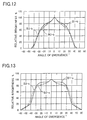
- Fig. 12 shows the brightness distribution of the light emerging from the light shield louver 5 when it offers a range ⁇ of viewing angles of 90° ( ⁇ 45°) as indicated by (b) in Fig. 2 and is illuminated with light having a brightness distribution as indicated by (B1), (B2), and (B3).
- (B1-b) indicates the case in which the incident light has a brightness distribution as indicated by (B1)
- (B2-b) indicates the case in which the incident light has a brightness distribution as indicated by (B2)
- B3-b) indicates the case in which the incident light has a brightness distribution as indicated by (B3).
- the relative brightness drops to 0% when the absolute value of the angle of emergence exceeds 45°.
- the relative brightness is 60% or more.
- the effective range of viewing angles is determined by ⁇ ⁇ 40°, and the relative brightness when the absolute value of the angle of emergence is ⁇ / 2 is about 70%.
- Fig. 13 shows the brightness distribution of the light emerging from the light shield louver 5 when it offers a range ⁇ of viewing angles of 120° ( ⁇ 60°) as indicated by (c) in Fig. 2 and is illuminated with light having a brightness distribution as indicated by (B1), (B2), and (B3).
- (B 1-c) indicates the case in which the incident light has a brightness distribution as indicated by (B1)
- (B2-c) indicates the case in which the incident light has a brightness distribution as indicated by (B2)
- B3-c) indicates the case in which the incident light has a brightness distribution as indicated by (B3).
- the relative brightness drops to 0% when the absolute value of the angle of emergence exceeds 60°.
- the relative brightness is in a range from 80% to 100%.
- the effective range of viewing angles is determined by ⁇ ⁇ 55°, and the relative brightness when the absolute value of the angle of emergence is ⁇ / 2 is about 80%.
- this liquid crystal display device 1 is not suitable for car-mounted use.
- Designing the light shield louver 5 to offer a range ⁇ of viewing angles of 120° or wider results in making the effective range of viewing angles wider than ⁇ 40°, and therefore it is particularly preferable that the range ⁇ of viewing angles be 110° or narrower.
- the range ⁇ of viewing angles is narrower than 30°, the peaks ( ⁇ a and ⁇ b in Fig. 5) in the brightness distribution come too close to each other, and this makes it impossible to obtain minimum brightness at an angle of incidence of 0°. Accordingly, it is preferable that the range ⁇ of viewing angles be 30° or wider.
- the prisms 8a have their vertices formed into points having a radius of 10 ⁇ m or smaller and therefore the light incident on the prisms 8a emerges therefrom in an uniform direction
- the prisms 8a have their vertices formed into curved surfaces and therefore the light incident thereon emerges therefrom in scattered directions. Accordingly, it is preferable that the prisms 8a have their vertices formed into points having a radius of 10 ⁇ m or smaller.
- Fig. 14 shows the brightness distribution of the light incident on the light shield louver 5 when the prisms 8a have still another shape.
- (B4) and (B5) indicate cases in which brightness has more than one maximum, with the peak interval of 30° and 50°, respectively.
- Fig. 15 shows the brightness distribution of the light emerging from the light shield louver 5 when it offers a range ⁇ of viewing angles of 120° ( ⁇ 60°) and is illuminated with light having a brightness distribution as indicated by (B4) and (B5).
- (B4-c) indicates the case in which the incident light has a brightness distribution as indicated by (B4)
- (B5-c) indicates the case in which the incident light has a brightness distribution as indicated by (B5).
- the relative brightness drops to 0% when the absolute value of the angle of emergence exceeds 60°. In a range of angles of emergence of about ⁇ 20° and ⁇ 25°, respectively, the relative brightness is 80% or more.
- the effective range of viewing angles is determined by ⁇ ⁇ 30°, and the relative brightness when the absolute value of the angle of emergence is ⁇ / 2 is about 130%.
- the effective range of viewing angles is determined by ⁇ ⁇ 34°, and the relative brightness when the absolute value of the angle of emergence is ⁇ / 2 is 100% or more.
- Fig. 16 is a front view showing the liquid crystal display device of a second embodiment of the invention.
- the light guide plate 3 has prism-shaped concave pits 3c formed in the back surface thereof.
- the pits 3c are so formed as to have an obtuse angle at their vertices.
- the light from the light sources 2 is incident on the light guide plate 3 substantially parallel to the exit surface 3a thereof.
- the light is then reflected from the slant surfaces of the pits 3c so as to emerge from the light guide plate 3 while traveling in slant directions relative to the direction perpendicular to the exit surface 3a.
- the light emerging from the light guide plate 3 exhibits high brightness within a predetermined range of angles that are slant relative to the direction normal to the light guide plate 3.
- the light emerging from the light guide plate 3 has been reflected from the slant surfaces of the pits 3c, and therefore this light emerges at the same intervals at which the pits 3c are arranged.
- the emerging light exhibits uneven brightness in phase with the intervals at which the pits 3c are arranged.
- a diffuser sheet 10 is provided between the light guide plate 3 and the light shield louver 5.
- the diffuser sheet 10 is made of a resin having a haze value of 40%, and serves to diffuse the light emerging from the light guide plate 3 so that uniform light is incident on the light shield louver 5. In this way, it is possible to direct light having a brightness distribution as shown in Fig. 5 described earlier to the light shield louver 5.
- this embodiment also, as in the first embodiment, by properly selecting the shape of the pits 3c, it is possible to give the light incident on the light shield louver 5 a brightness distribution such that brightness is at a minimum around an angle of incidence of 0°. In this way, it is possible to limit the light emerging from the light shield louver 5 within a predetermined effective range of viewing angles. This makes it possible to realize a liquid crystal display device 1 that ensures reduced variation in the brightness of the light emerging therefrom and that thus offers satisfactory viewability.
- Fig. 17 is a front view showing the liquid crystal display device of a third embodiment of the invention.
- a Fresnel sheet 22 is disposed between the light shield louver 23 and the prism sheet 8, and that the light shield louver 23 has its light-absorbing layers 23b arranged with an inclination.
- Fig. 18 is a sectional view showing the details of the light shield louver 23.
- the light shield louver 23 has its light-absorbing layers 23b so formed as to be inclined by an angle of ⁇ relative to the direction normal to the light shield louver 23.
- the light shield louver 23 exhibits highest transmittance to the light L1 that travels parallel to the light-absorbing layers 23b.
- Fig. 19 is a sectional view showing the details of the Fresnel sheet 22.
- a Fresnel portion 22a On the surface of the Fresnel sheet 22 is formed a Fresnel portion 22a having a periodical, sawtooth-shaped pattern.
- the Fresnel portion 22a is made of a polyester-based hardening resin, and is laid on a base member formed out of a 100 ⁇ m thick PET film.
- the boundary between two adjacent teeth is formed as a surface perpendicular to the Fresnel sheet 22.
- Fig. 20 shows the brightness distribution of the light incident on the light shield louver 23, i.e. the light emerging from the Fresnel sheet 22.
- the angle of incidence (°) with respect to the light shield louver 23 is taken along the horizontal axis
- the relative brightness (%) is taken along the vertical axis.
- the prisms 8a of the prism sheet 8 have a vertical angle of 90°, and the light emerging from the prism sheet 8 exhibits, as indicated by a broken line, a brightness distribution symmetrical about the direction normal thereto, i.e. the same brightness distribution as indicated by (B) in Fig. 5.
- the slant surfaces of the Fresnel sheet 22 are inclined by an angle of y (see Fig. 19) relative to the direction in which it has the periodic, sawtooth-shaped pattern.
- the light incident on the Fresnel sheet 22 is refracted so that the light emerging therefrom has a brightness distribution that is non-symmetrical about the direction normal thereto but that is substantially symmetrical about a direction about 15° shifted from the normal direction. That is, the Fresnel sheet 22 shifts the average of the angle of incidence of the light incident on the light shield louver 23 (hereinafter, this angle will be referred to as the "average angle of incidence") from 0° to -15°.
- the inclination angle ⁇ (see Fig. 18) of the light-absorbing layers 23b of the light shield louver 23 is made equal to 15°.
- the light shield louver 23 exhibits the highest transmittance at an angle of incidence of -15°.
- the light shield louver 23 here offers a range ⁇ of viewing angles of 120°.
- the transmittance (%) is taken along the vertical axis
- the angle of incidence (°) is taken along the horizontal axis.
- the light emerging from the light shield louver 23 exhibits a brightness distribution as shown in Fig. 22.
- the relative brightness (%) is taken along the vertical axis
- the angle of emergence (°) is taken along the horizontal axis. Outside a range of angles of emergence of -15° ⁇ 40°, the relative brightness relative to the highest brightness is 5% or less; within a range of angles of emergence of -15° ⁇ 30°, the relative brightness is about 80% or more.
- the liquid crystal display device 1 of this embodiment is mounted on a car or used in similar applications, there is no need to install it in such a way that the viewer's eyes lie in the direction normal thereto. Even when the liquid crystal display device 1 is installed at different angles, as long as it is provided with a light shield louver 23 and a Fresnel sheet 22 with different inclination angles ⁇ and ⁇ (see Figs. 18 and 19), it is possible to secure high brightness in a predetermined range of angles around the direction in which the viewer's eyes lie. This helps alleviate restrictions on how the liquid crystal display device 1 should be installed in a car or the like and thereby increase flexibility in installation layout.
- the light sources 2 are composed of a plurality of fluorescent lamps. By varying the brightness of the fluorescent lamps, it is possible to reduce the brightness of the light that emerges from the liquid crystal display device 1 outside the desired range of directions of emergence. How this is achieved will be described below taking up the third embodiment as an example. As shown in Fig. 17 described earlier, as the light sources 2, two fluorescent lamps 2a and 2b are arranged in the direction normal to the liquid crystal panel 6 along each of two opposite sides of the light guide plate 3.
- the fluorescent lamps 2a and 2b are controlled by an inverter (not shown).
- the inverter is of a single-DC-input, two-transformer type, and is so configured as to permit adjustment of the duty factor through the operation of a variable resistor. When the input signal from the variable resistor is within a predetermined range, all the fluorescent lamps 2a and 2b are lit to emit their maximum amount of light.
- the fluorescent lamps 2b farther from the liquid crystal panel 6 are lit to emit their maximum amount of light, and the fluorescent lamps 2a nearer thereto are lit to emit a smaller amount of light according to how high the input signal is.
- the fluorescent lamps 2a nearer to the liquid crystal panel 6 are lit to emit their maximum amount of light, and the fluorescent lamps 2b farther therefrom are lit to emit a smaller amount of light according to how low the input signal is.
- Fig. 23 shows the brightness distribution of the light incident on the light shield louver 23 when the amount of light emitted from the light sources 2 is adjusted.
- the angle of incidence (°) is taken along the horizontal axis
- the relative brightness (%) is taken along the vertical axis.
- D1 indicates a case in which the fluorescent lamps 2a nearer to the light shield louver 23 are lit to emit 50% of the amount of light they emit in the case indicated by B' in Fig. 20 described earlier
- D2 indicates a case in which the fluorescent lamps 2a are switched off In either case, the fluorescent lamps 2b farther from the light shield louver 23 are lit to emit their maximum amount of light.
- the light shield louver 23 exhibits transmittance as shown in Fig. 21 described earlier, the light emerging from the light shield louver 23 exhibits a brightness distribution as shown in Fig. 24.
- D1' and D2' indicate the cases in which the incident light has a brightness distribution as indicated by D1 and D2, respectively.
- the angle of emergence (°) is taken along the horizontal axis, and the relative brightness (%) is taken along the vertical axis.
- a viewer M1 with a high sitting height typically observes the light emerging therefrom within a range of angles of emergence from about 0° to about +20°
- a viewer M2 with an average sitting height typically observes the light emerging therefrom within a range of angles of emergence from about 0° to about -20°
- a viewer M3 with a low sitting height typically observes the light emerging therefrom within a range of angles of emergence from about -20° to about -40°.
- the viewers M1, M2, and M3 can reduce the amount of light that is typically not used for their observation and thereby save the electric power consumed by the liquid crystal display device 1.
- the fluorescent lamps 2a an 2b are made to emit their maximum amount of light, so that the emerging light exhibits a brightness distribution as shown in Fig. 22 described earlier. This permits the viewers to observe a sharp image in a wide range of angles, and also prevents the image from being projected onto the windshield.
- the liquid crystal panel 6 may be of a so-called semitransparent-reflective type.
- a liquid crystal panel of a semitransparent-reflective type displays an image by reflecting ambient light when ambient light is available and by transmitting the light emitted from the backlight 7 when no ambient light is available.
- the light shield louver 5 or 23 may be disposed either in front of or behind the liquid crystal panel 6.
- the liquid crystal panel 6 is of a semitransparent-reflective type
- disposing the light shield louver 5 or 23 on the exit surface of the liquid crystal panel 6 lowers the efficiency with which the liquid crystal panel 6 takes in ambient light. Therefore, in such a case, it is preferable to dispose the light shield louver 5 or 23 between the liquid crystal panel 6 and the light guide plate 3.
Landscapes
- Physics & Mathematics (AREA)
- General Physics & Mathematics (AREA)
- Optics & Photonics (AREA)
- Nonlinear Science (AREA)
- Mathematical Physics (AREA)
- Chemical & Material Sciences (AREA)
- Crystallography & Structural Chemistry (AREA)
- Liquid Crystal (AREA)
- Optical Elements Other Than Lenses (AREA)
- Planar Illumination Modules (AREA)
- Devices For Indicating Variable Information By Combining Individual Elements (AREA)
Applications Claiming Priority (4)
| Application Number | Priority Date | Filing Date | Title |
|---|---|---|---|
| JP2000237884 | 2000-08-07 | ||
| JP2000237884 | 2000-08-07 | ||
| JP2001184841 | 2001-06-19 | ||
| JP2001184841A JP2002124112A (ja) | 2000-08-07 | 2001-06-19 | バックライト及び液晶表示装置 |
Publications (1)
| Publication Number | Publication Date |
|---|---|
| EP1180641A1 true EP1180641A1 (de) | 2002-02-20 |
Family
ID=26597449
Family Applications (1)
| Application Number | Title | Priority Date | Filing Date |
|---|---|---|---|
| EP01118987A Withdrawn EP1180641A1 (de) | 2000-08-07 | 2001-08-06 | Rückbeleuchtungsvorrichtung und Flüssigkristallanzeige |
Country Status (6)
| Country | Link |
|---|---|
| US (1) | US6609807B2 (de) |
| EP (1) | EP1180641A1 (de) |
| JP (1) | JP2002124112A (de) |
| KR (1) | KR100394563B1 (de) |
| CN (2) | CN1530712A (de) |
| TW (1) | TWI288273B (de) |
Cited By (2)
| Publication number | Priority date | Publication date | Assignee | Title |
|---|---|---|---|---|
| AU2002327420B9 (en) * | 2001-08-06 | 2003-02-24 | Mei, Incorporated | Document validator subassembly |
| US7430028B2 (en) | 2004-11-19 | 2008-09-30 | Au Optronics Corp. | Viewing-angle adjustable liquid crystal display and method for adjusting the same |
Families Citing this family (50)
| Publication number | Priority date | Publication date | Assignee | Title |
|---|---|---|---|---|
| JP2003137004A (ja) * | 2001-10-31 | 2003-05-14 | Nippon Seiki Co Ltd | 車両用表示装置 |
| KR100515676B1 (ko) * | 2001-12-22 | 2005-09-23 | 엘지.필립스 엘시디 주식회사 | 액정표시장치의 백라이트 유닛 및 그 조립방법 |
| JP4045097B2 (ja) * | 2001-12-28 | 2008-02-13 | シャープ株式会社 | バックライト装置及びこれを用いた液晶表示装置 |
| KR100803181B1 (ko) * | 2002-04-19 | 2008-02-14 | 삼성전자주식회사 | 백라이트 어셈블리 |
| KR100873085B1 (ko) * | 2002-06-22 | 2008-12-09 | 삼성전자주식회사 | 백 라이트 어셈블리 및 이를 갖는 직하형 액정 표시 장치 |
| KR100883094B1 (ko) * | 2002-07-04 | 2009-02-11 | 삼성전자주식회사 | 백라이트 어셈블리 및 이를 이용한 액정표시장치 |
| WO2004015330A1 (ja) * | 2002-08-09 | 2004-02-19 | Mitsubishi Rayon Co., Ltd. | 面光源装置 |
| TW542883B (en) * | 2002-08-16 | 2003-07-21 | Au Optronics Corp | Backlight unit for flat panel liquid crystal display |
| US6808281B2 (en) * | 2002-12-14 | 2004-10-26 | Quanta Display Incorporation | Backlight module having concave struture |
| TW594171B (en) * | 2003-04-18 | 2004-06-21 | Hannstar Display Corp | Liquid crystal display and light source device thereof |
| JP2005055481A (ja) * | 2003-06-09 | 2005-03-03 | Toyota Industries Corp | 光学素子、面状照明装置及び表示装置 |
| JP4081448B2 (ja) * | 2004-01-14 | 2008-04-23 | シャープ株式会社 | 液晶表示装置 |
| KR101016750B1 (ko) * | 2004-04-19 | 2011-02-25 | 엘지디스플레이 주식회사 | 액정표시장치의 검사장치 |
| CN100445810C (zh) * | 2004-09-07 | 2008-12-24 | 夏普株式会社 | 显示装置、视野角控制装置以及电子设备 |
| JP4629049B2 (ja) * | 2004-10-04 | 2011-02-09 | シャープ株式会社 | 表示装置および電子機器 |
| KR20060037687A (ko) * | 2004-10-28 | 2006-05-03 | 삼성전자주식회사 | 반사 시트 및 이를 갖는 표시장치 |
| JP2006147293A (ja) * | 2004-11-18 | 2006-06-08 | Toppan Printing Co Ltd | バックライトユニット |
| JP4311366B2 (ja) * | 2005-03-28 | 2009-08-12 | 日本電気株式会社 | 光源装置、表示装置、端末装置及び光学部材 |
| JP4673676B2 (ja) * | 2005-06-10 | 2011-04-20 | シチズン電子株式会社 | バックライト装置 |
| KR101096759B1 (ko) * | 2005-06-16 | 2011-12-26 | 삼성전자주식회사 | 백라이트 어셈블리 및 이를 이용한 액정표시장치 |
| KR101214945B1 (ko) * | 2005-08-17 | 2012-12-24 | 삼성디스플레이 주식회사 | 백라이트 어셈블리 및 이를 이용한 표시장치 |
| JP4757585B2 (ja) * | 2005-09-21 | 2011-08-24 | Nec液晶テクノロジー株式会社 | 光源ユニット及び照明装置 |
| JP5019095B2 (ja) * | 2005-12-19 | 2012-09-05 | Dic株式会社 | 遮光反射粘着テープ及びそれを用いたlcdモジュール |
| CN101004515A (zh) * | 2006-01-21 | 2007-07-25 | 鸿富锦精密工业(深圳)有限公司 | 直下式背光模组 |
| TWI326787B (en) * | 2006-02-09 | 2010-07-01 | Au Optronics Corp | Backlight module and liquid crystal display device incorporating the same |
| JP2007279424A (ja) * | 2006-04-07 | 2007-10-25 | Three M Innovative Properties Co | 覗き見防止シート及びそれを含むディスプレイ装置 |
| JP2008089728A (ja) * | 2006-09-29 | 2008-04-17 | Nec Lcd Technologies Ltd | 光学素子、それを用いた照明装置、表示装置、および電子機器 |
| JP2008096895A (ja) * | 2006-10-16 | 2008-04-24 | Olympus Corp | 顕微鏡用照明装置 |
| JP4914731B2 (ja) * | 2007-02-01 | 2012-04-11 | 矢崎総業株式会社 | 車両用表示ユニット |
| BRPI0816641A2 (pt) | 2007-10-16 | 2015-03-10 | 3M Innovative Properties Co | "filme de controle de luz, conjunto de iluminação colimada e tela de cristal líquido" |
| TWI363906B (en) * | 2008-07-02 | 2012-05-11 | Au Optronics Corp | Backlight module and back plate and base thereof |
| TWI429992B (zh) * | 2010-02-26 | 2014-03-11 | Young Lighting Technology Corp | 背光模組 |
| TWI430221B (zh) * | 2011-05-16 | 2014-03-11 | Au Optronics Corp | 具有寬水平視角範圍及窄垂直視角範圍的顯示系統 |
| JP2013061436A (ja) * | 2011-09-13 | 2013-04-04 | Lenovo Singapore Pte Ltd | 液晶シャッタを備える電子機器 |
| TWI460714B (zh) * | 2011-12-27 | 2014-11-11 | Himax Media Solutions Inc | 可調適控制發光二極體背光源的系統及方法 |
| CN102767754A (zh) * | 2012-06-25 | 2012-11-07 | 中航华东光电有限公司 | 一种背光模组结构 |
| DE102013217709A1 (de) * | 2013-09-05 | 2015-03-05 | Carl Zeiss Microscopy Gmbh | Beleuchtungsvorrichtung und digitaler Profilprojektor |
| JP6005016B2 (ja) * | 2013-09-11 | 2016-10-12 | 三菱電機株式会社 | 移動体用表示装置 |
| CN103605237B (zh) * | 2013-11-22 | 2016-06-15 | 京东方科技集团股份有限公司 | 一种显示装置 |
| CN103591514B (zh) * | 2013-11-22 | 2016-03-02 | 京东方科技集团股份有限公司 | 一种背光模组及液晶显示装置 |
| CN203748176U (zh) * | 2014-01-20 | 2014-07-30 | 苏州贺尔新电子有限公司 | 一种新型散热反射片 |
| JP2017053992A (ja) * | 2015-09-09 | 2017-03-16 | パナソニックIpマネジメント株式会社 | 車載用液晶表示装置及び車両 |
| US9939576B2 (en) * | 2016-01-27 | 2018-04-10 | Microsoft Technology Licensing, Llc | Providing structural support via backlight system |
| JP6932977B2 (ja) * | 2016-05-06 | 2021-09-08 | 大日本印刷株式会社 | 映像源ユニット、及び液晶表示装置 |
| CN109377918A (zh) * | 2018-11-21 | 2019-02-22 | 苏州佳世达电通有限公司 | 成像模组及电子装置 |
| CN111487711A (zh) * | 2020-05-29 | 2020-08-04 | 北京小米移动软件有限公司 | 光学部件、背光模组、电子设备及光学部件的制作方法 |
| CN112666752A (zh) * | 2020-12-28 | 2021-04-16 | 深圳创维汽车智能有限公司 | 背光模组组件、液晶显示器及汽车 |
| JP2023100070A (ja) | 2022-01-05 | 2023-07-18 | シャープディスプレイテクノロジー株式会社 | 液晶表示装置 |
| CN114442347B (zh) * | 2022-01-27 | 2023-04-28 | 绵阳惠科光电科技有限公司 | 显示模组 |
| JP2023125175A (ja) * | 2022-02-28 | 2023-09-07 | シャープディスプレイテクノロジー株式会社 | 照明装置及び表示装置 |
Citations (5)
| Publication number | Priority date | Publication date | Assignee | Title |
|---|---|---|---|---|
| US5295221A (en) * | 1992-12-01 | 1994-03-15 | Light Quest Corporation | Compact, light efficient, illuminated transparency frame |
| EP0588504A1 (de) * | 1992-09-16 | 1994-03-23 | International Business Machines Corporation | Hinterbeleuchtungsvorrichtung für eine Flüssigkristall-Anzeigevorrichtung |
| EP0607930A2 (de) * | 1993-01-19 | 1994-07-27 | Canon Kabushiki Kaisha | Lichtleiter und mit diesem ausgestattete Belichtungs-, Bildlese- und Informationsverarbeitungsvorrichtung |
| US5600456A (en) * | 1994-09-01 | 1997-02-04 | Nec Corporation | Transmission liquid crystal display with a reduced dependency of a display quality upon a visual angle |
| WO2000019145A1 (en) * | 1998-09-25 | 2000-04-06 | Alliedsignal Inc. | Illumination system having an array of linear prisms |
Family Cites Families (19)
| Publication number | Priority date | Publication date | Assignee | Title |
|---|---|---|---|---|
| JPH0727137B2 (ja) * | 1988-06-02 | 1995-03-29 | 三菱レイヨン株式会社 | 面光源素子 |
| JP2520739B2 (ja) * | 1989-08-30 | 1996-07-31 | 株式会社エンプラス | 照明装置 |
| JPH04145485A (ja) * | 1990-10-05 | 1992-05-19 | Mitsubishi Rayon Co Ltd | 光源装置 |
| JP3498750B2 (ja) * | 1992-11-20 | 2004-02-16 | 日本ゼオン株式会社 | 熱硬化性樹脂成形材料、成形品、及び熱可塑性ノルボルネン系樹脂粒子 |
| JPH0829786A (ja) * | 1994-05-11 | 1996-02-02 | Sharp Corp | 照明装置およびそれを用いた液晶表示装置 |
| JP3528994B2 (ja) * | 1994-11-08 | 2004-05-24 | 大日本印刷株式会社 | 液晶表示装置用平行光源及びそれを用いた液晶表示装置 |
| JPH08171995A (ja) * | 1994-12-15 | 1996-07-02 | Sony Corp | 蛍光管のインバータ駆動回路 |
| EP0865904B1 (de) * | 1995-06-14 | 2003-02-12 | Mitsubishi Rayon Co., Ltd. | Oberflächenlichtquelle |
| JP2950219B2 (ja) * | 1995-10-13 | 1999-09-20 | オムロン株式会社 | 面光源装置、当該面光源装置を用いた画像表示装置及び当該面光源装置に用いるプリズムアレイ |
| JPH09105804A (ja) * | 1995-10-13 | 1997-04-22 | Konica Corp | 光制御シート、面光源装置及び液晶表示装置 |
| JPH11153795A (ja) * | 1997-11-20 | 1999-06-08 | Hitachi Ltd | 液晶表示装置 |
| JPH11190841A (ja) | 1997-12-25 | 1999-07-13 | Casio Comput Co Ltd | 表示装置 |
| JPH11352900A (ja) * | 1998-04-06 | 1999-12-24 | Casio Comput Co Ltd | 表示装置 |
| JP2000003609A (ja) * | 1998-06-16 | 2000-01-07 | Enplas Corp | サイドライト型面光源装置及び液晶表示装置 |
| JP2000098374A (ja) * | 1998-09-25 | 2000-04-07 | Casio Comput Co Ltd | 液晶表示装置 |
| JP2000164016A (ja) * | 1998-09-24 | 2000-06-16 | Sharp Corp | 面光源装置 |
| FR2802308B1 (fr) * | 1999-12-09 | 2002-03-08 | Gc Comm | Procede et dispositif d'usinage par laser de guides de lumiere, guides de lumiere obtenus et ecrans retro-elaires incorporant ces guides |
| KR100806093B1 (ko) * | 2000-04-27 | 2008-02-21 | 가부시키가이샤 구라레 | 면광원소자 및 이를 사용한 표시장치 |
| US6502947B2 (en) * | 2001-03-30 | 2003-01-07 | Mitsubishi Rayon Co., Ltd. | Planar light source device and liquid crystal display apparatus |
-
2001
- 2001-06-19 JP JP2001184841A patent/JP2002124112A/ja active Pending
- 2001-08-06 EP EP01118987A patent/EP1180641A1/de not_active Withdrawn
- 2001-08-06 US US09/921,753 patent/US6609807B2/en not_active Expired - Lifetime
- 2001-08-07 KR KR10-2001-0047546A patent/KR100394563B1/ko not_active IP Right Cessation
- 2001-08-07 CN CNA2004100322942A patent/CN1530712A/zh active Pending
- 2001-08-07 CN CNB01125081XA patent/CN1170191C/zh not_active Expired - Fee Related
- 2001-08-07 TW TW090119255A patent/TWI288273B/zh not_active IP Right Cessation
Patent Citations (5)
| Publication number | Priority date | Publication date | Assignee | Title |
|---|---|---|---|---|
| EP0588504A1 (de) * | 1992-09-16 | 1994-03-23 | International Business Machines Corporation | Hinterbeleuchtungsvorrichtung für eine Flüssigkristall-Anzeigevorrichtung |
| US5295221A (en) * | 1992-12-01 | 1994-03-15 | Light Quest Corporation | Compact, light efficient, illuminated transparency frame |
| EP0607930A2 (de) * | 1993-01-19 | 1994-07-27 | Canon Kabushiki Kaisha | Lichtleiter und mit diesem ausgestattete Belichtungs-, Bildlese- und Informationsverarbeitungsvorrichtung |
| US5600456A (en) * | 1994-09-01 | 1997-02-04 | Nec Corporation | Transmission liquid crystal display with a reduced dependency of a display quality upon a visual angle |
| WO2000019145A1 (en) * | 1998-09-25 | 2000-04-06 | Alliedsignal Inc. | Illumination system having an array of linear prisms |
Non-Patent Citations (1)
| Title |
|---|
| TAI C-Y ET AL: "FLAT COLLIMATOR: A BACKLIGHTING ASSEMBLY UTILIZING MICROPRISMS FOR HIGH ENERGY EFFICIENCY", SID INTERNATIONAL SYMPOSIUM DIGEST OF APPLICATIONS PAPERS. SAN JOSE, JUNE 14 - 16, 1994, SANTA ANA, SID, US, vol. 25, 14 June 1994 (1994-06-14), pages 10 - 13, XP000492839, ISSN: 0097-0966 * |
Cited By (6)
| Publication number | Priority date | Publication date | Assignee | Title |
|---|---|---|---|---|
| AU2002327420B9 (en) * | 2001-08-06 | 2003-02-24 | Mei, Incorporated | Document validator subassembly |
| EP1415188A2 (de) * | 2001-08-06 | 2004-05-06 | Mars Incorporated | Dokumentvalidierer-baugruppe |
| EP1415188A4 (de) * | 2001-08-06 | 2005-06-08 | Mars Inc | Dokumentvalidierer-baugruppe |
| US6994203B2 (en) | 2001-08-06 | 2006-02-07 | Mars Incorporated | Document validator subassembly |
| AU2002327420B2 (en) * | 2001-08-06 | 2007-05-31 | Mei, Incorporated | Document validator subassembly |
| US7430028B2 (en) | 2004-11-19 | 2008-09-30 | Au Optronics Corp. | Viewing-angle adjustable liquid crystal display and method for adjusting the same |
Also Published As
| Publication number | Publication date |
|---|---|
| US20020018341A1 (en) | 2002-02-14 |
| US6609807B2 (en) | 2003-08-26 |
| CN1346068A (zh) | 2002-04-24 |
| CN1170191C (zh) | 2004-10-06 |
| KR100394563B1 (ko) | 2003-08-14 |
| TWI288273B (en) | 2007-10-11 |
| JP2002124112A (ja) | 2002-04-26 |
| KR20020012524A (ko) | 2002-02-16 |
| CN1530712A (zh) | 2004-09-22 |
Similar Documents
| Publication | Publication Date | Title |
|---|---|---|
| US6609807B2 (en) | Backlight and liquid crystal display device | |
| US20030184993A1 (en) | Backlight and liquid crystal display device employing it | |
| KR101277872B1 (ko) | 다기능 향상 필름 | |
| JP3642381B2 (ja) | 導光板、面光源装置及び反射型液晶表示装置 | |
| JP5291469B2 (ja) | バックライト構造 | |
| US6139162A (en) | Lens light guide plate and surface light equipment using the same | |
| US20050243551A1 (en) | Lighting system image display apparatus using the same and light diffusion plate used therefor | |
| JP4423933B2 (ja) | 光学シートとそれを用いたバックライトユニットおよびディスプレイ | |
| JP2009110765A (ja) | 面光源装置及び液晶表示装置 | |
| JP2001143515A (ja) | プリズムシートおよび面光源素子 | |
| EP0989356A1 (de) | Vorrichtung zur Beleuchtung einer Fläche in mehrfache Richtungen in konzentrieter Weise | |
| US20070133225A1 (en) | Lighting unit, electro-optic device, and electronic apparatus | |
| US6735373B2 (en) | Plane light source unit and liquid-crystal display device | |
| JP2008218418A (ja) | 面光源装置及びそれに用いる導光体 | |
| JP4119633B2 (ja) | 面光源装置及びそれに用いる導光体 | |
| US6585386B1 (en) | Light pipe, surface light source device and reflection type liquid-crystal display device | |
| JP4400845B2 (ja) | 光拡散シートおよびそれを用いた映像表示素子、面光源装置 | |
| JP6690190B2 (ja) | 面光源装置、映像源ユニット、及び液晶表示装置 | |
| JPH11160504A (ja) | 光制御シート | |
| JP4125467B2 (ja) | 面光源素子およびレンズシート | |
| JP2000067626A (ja) | 面光源装置及びそれを用いた画像表示装置 | |
| JP6844730B2 (ja) | 面光源装置、映像源ユニット、及び液晶表示装置 | |
| CN220626820U (zh) | 背光模组及显示装置 | |
| JP2001093314A (ja) | 面光源装置及びこれを用いた液晶ディスプレイ装置 | |
| JP2018041717A (ja) | 面光源装置および表示装置 |
Legal Events
| Date | Code | Title | Description |
|---|---|---|---|
| PUAI | Public reference made under article 153(3) epc to a published international application that has entered the european phase |
Free format text: ORIGINAL CODE: 0009012 |
|
| AK | Designated contracting states |
Kind code of ref document: A1 Designated state(s): DE FR Kind code of ref document: A1 Designated state(s): AT BE CH CY DE DK ES FI FR GB GR IE IT LI LU MC NL PT SE TR |
|
| AX | Request for extension of the european patent |
Free format text: AL;LT;LV;MK;RO;SI |
|
| 17P | Request for examination filed |
Effective date: 20020523 |
|
| AKX | Designation fees paid |
Free format text: DE FR |
|
| 17Q | First examination report despatched |
Effective date: 20051012 |
|
| STAA | Information on the status of an ep patent application or granted ep patent |
Free format text: STATUS: THE APPLICATION IS DEEMED TO BE WITHDRAWN |
|
| 18D | Application deemed to be withdrawn |
Effective date: 20070605 |