EP1171725B1 - Dispositif de transport - Google Patents
Dispositif de transport Download PDFInfo
- Publication number
- EP1171725B1 EP1171725B1 EP00934904A EP00934904A EP1171725B1 EP 1171725 B1 EP1171725 B1 EP 1171725B1 EP 00934904 A EP00934904 A EP 00934904A EP 00934904 A EP00934904 A EP 00934904A EP 1171725 B1 EP1171725 B1 EP 1171725B1
- Authority
- EP
- European Patent Office
- Prior art keywords
- transport device
- wound
- guiding chain
- energy guiding
- section
- Prior art date
- Legal status (The legal status is an assumption and is not a legal conclusion. Google has not performed a legal analysis and makes no representation as to the accuracy of the status listed.)
- Expired - Lifetime
Links
Images


Classifications
-
- H—ELECTRICITY
- H02—GENERATION; CONVERSION OR DISTRIBUTION OF ELECTRIC POWER
- H02G—INSTALLATION OF ELECTRIC CABLES OR LINES, OR OF COMBINED OPTICAL AND ELECTRIC CABLES OR LINES
- H02G11/00—Arrangements of electric cables or lines between relatively-movable parts
- H02G11/02—Arrangements of electric cables or lines between relatively-movable parts using take-up reel or drum
-
- B—PERFORMING OPERATIONS; TRANSPORTING
- B66—HOISTING; LIFTING; HAULING
- B66C—CRANES; LOAD-ENGAGING ELEMENTS OR DEVICES FOR CRANES, CAPSTANS, WINCHES, OR TACKLES
- B66C13/00—Other constructional features or details
- B66C13/12—Arrangements of means for transmitting pneumatic, hydraulic, or electric power to movable parts of devices
-
- F—MECHANICAL ENGINEERING; LIGHTING; HEATING; WEAPONS; BLASTING
- F16—ENGINEERING ELEMENTS AND UNITS; GENERAL MEASURES FOR PRODUCING AND MAINTAINING EFFECTIVE FUNCTIONING OF MACHINES OR INSTALLATIONS; THERMAL INSULATION IN GENERAL
- F16G—BELTS, CABLES, OR ROPES, PREDOMINANTLY USED FOR DRIVING PURPOSES; CHAINS; FITTINGS PREDOMINANTLY USED THEREFOR
- F16G13/00—Chains
- F16G13/12—Hauling- or hoisting-chains so called ornamental chains
- F16G13/16—Hauling- or hoisting-chains so called ornamental chains with arrangements for holding electric cables, hoses, or the like
-
- B—PERFORMING OPERATIONS; TRANSPORTING
- B65—CONVEYING; PACKING; STORING; HANDLING THIN OR FILAMENTARY MATERIAL
- B65H—HANDLING THIN OR FILAMENTARY MATERIAL, e.g. SHEETS, WEBS, CABLES
- B65H2701/00—Handled material; Storage means
- B65H2701/30—Handled filamentary material
- B65H2701/39—Other types of filamentary materials or special applications
- B65H2701/3911—Chains
Definitions
- the invention relates to transport device, which essentially has the shape of a cable drum on which one with Cable or other lines equipped energy chain is wound with a substantially about an axis of rotation arranged the transport device, preferably cylindrical central body and one in the area of the front End of the central body arranged radially from this extending end limiting elements.
- Such a transport device is for example from the EP 0 699 616 known.
- the chains to be transported can already be completely assembled with cables, plugs, end mounting parts and Strain reliefs must be equipped so that they are only connected Need to become.
- Such energy chains can be of considerable length and weight and are then difficult to handle.
- a long chain in a guide trough on the floor or on a crane boom at a height of about 10 to 20 m is large trained energy chains with a width of 10 up to 30 cm only under great circumstances, as a such a chain can be up to 100 m long.
- the invention is based, the handling and the task Simplify transportation of energy chains.
- this is achieved by providing means are used to divide the space between the end limitation elements in at least a first section, in the one that sticks out of one end of the energy chain Lines are wound, and a second section, in on which the actual energy supply chain is wound.
- the central body is preferably a circular cylindrical Hollow body designed to ensure easy winding and the occurrence of a polygon effect as far as possible to prevent.
- the system chain is in the gap between the two end limiting elements by rotating the Central body can be wound up.
- the space between the End limiting elements can be wider or wider as needed be made narrower.
- the inside width of the drum can e.g. correspond approximately to the chain width, resulting in a radial Winding, but at the same time a drum of low Longitudinal dimensions leads. This version is called the radial embodiment designated.
- the inside width of the Drum a multiple of the chain width.
- the winding can be designed in one layer or several Layers. This leads in comparison to the first embodiment to a wider drum, but a small one for that has radial dimensions.
- This second version will be released in hereinafter referred to as the axial embodiment.
- end limiting elements slidably arranged on the central body are to the transport device according to needs for chain systems or chains of different widths to be able to use.
- the central body does not necessarily have to be a closed one Body, but can also consist of several side by side arranged bars or webs exist.
- the end limit elements are preferably circular End plates formed, as this is a particularly simple Unrolling the chain systems from the transport device allows.
- the transport device can be used for winding and Unwinding the system chain can then simply be rolled.
- To the Improve the handling of the transport device are on the Handles provided in the installed position on the outer side of the end plates, with the help of which the transport device from time to time can roll up.
- the axial design the division by circular dividing discs takes place between which struts are spanned are.
- the dividing washers or struts extend radially away from the central body to the between the End disks provided space in - seen from the side - to divide disc-shaped sections in which the cables and Energy supply chain can be wound defined.
- the central body fixed struts are provided, which are radial extend from the central body. Between these struts and / or the end disks, connecting struts are then arranged, in the installed position, preferably colinear with the axis of rotation of the transport device. On these connecting struts can be wrapped in energy chains or cables become.
- the connecting struts are on the radial struts movably attached to the transport device to be able to remodel depending on the application.
- the energy chain or the cable is first wound onto the central body.
- Connecting struts or connecting elements used which in turn are essentially colinear with the axis of rotation of the transport device.
- the further one The energy supply chain is wound on the connecting struts. So in the radial embodiment radially spaced sections when winding the Energy chain by inserting the connecting struts generated. Depending on your wishes, you can insert additional connecting struts formed radially spaced further sections become.
- a fastening device for the energy chain or the end fastening part on the transport device provided. This is usually a fastening device to the central body or the side End limiting elements arranged.
- the transport device can be provided with an axis, which runs coaxially to the axis of rotation through the central body.
- the axis can be used both fixed and detachable be usable.
- On the side of the transport device protruding ends of the axis can be the transport device be lifted for transportation. This takes place, for example, by chains enclosing the axis, which are lifted by a crane.
- To turn the To prevent transport device when lifting are between Brakes that can be placed on the chain or rope on the axle arranged.
- the axis does not have to be designed as a continuous axis. It is also possible to have cylindrical rods made of solid material the outside of the end plates.
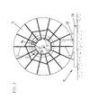
- the transport device is designated 1 in its entirety and the energy chain with 2.
- the transport device 1 has the shape of a very large dimensioned cable drum with a coaxial to the axis of rotation arranged in the transport device, cylindrical Central body 3, on which the energy chain 2, at least partially, is windable.
- end plates 4 and 5 In the area of the front ends of the central body 3 are circular end plates 4 and 5 arranged.
- Radial struts spaced longitudinally from the end disks 6, 7, 8, 9 attached to the central body 3.
- connecting struts Between Radial struts 6, 7, 8, 9 are attached to connecting struts, which also space the radial struts 6, 7, 8, 9 apart and stabilize.
- the radial struts 6, 7, 8, 9 and Connection struts 10, 11 are in the present case as C-profiles Made of steel.
- the connecting struts 10, 11 are axial slidable along the longitudinal axis of the radial struts 6, 7, 8, 9 and can be fixed in any position become.
- the radial struts can also in the axial direction be placed anywhere on the central body.
- an axis designated in its entirety with 12 which is rotatably connected to the end plates 4 and 5.
- the free ends of the axis 12 sit on stands 13 in the rest position and 14 on.
- the transport device is on a fixing device according to the invention arranged in their entirety with 15 is designated.
- the more precise structure of the radial struts 6, 7 is shown in the figure 2 can be seen. From this figure it can also be seen that in addition to the described radial struts 6, 7 along the entire outer circumferential surface of the central body 3 radially protruding Radial struts are arranged. Between 2 in Radial struts lying one above the other as viewed in FIG are the colinear connecting struts to the axis 12 10 and 11 arranged to ensure sufficient stability of the To ensure transport device 1.
- This fastening device in the present case consists of a block that the end fastening part 16 engages behind.
- this block 18 prevents this Kinking of the energy chain 2 when winding and prevented also the heavy stress on the end attachment part 16 through the accumulating energy chain 2.
- the fixing device 15 for preventing the Rolling or a rotation of the transport device 1 exists essentially from one that can be placed on a surface Base on which a beam 20 with an arcuate recess 21 is attached.
- the radius of the arcuate recess corresponds essentially to the outer radius of the end plate 5.
- the transport device according to the invention makes it possible for the first time easy to lay even heavy energy chains.
- the transport device is placed over a guide trough unrolled, which take up the energy chain should.
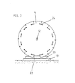
- FIG. 4 is an axial embodiment of the invention Transport device shown in the front view. This embodiment is axially longer than that in FIG. 1 shown, but it has less in the radial direction Dimensions.
- the free end of the cable 25 is initially wound on the section I of the transport device 26.
- the actual energy supply chain is based on Section II wound in alternating layers.
- the end of the cables 27 is wound up on the outer layer of the energy chain 28.
- Figure 5 finally represents a radial embodiment of the Transport device according to the invention in the front view
- the free end of the cable 29 is first on a central body to a lesser extent than the main central body wound.
- the energy chain 31 will on the main central body forming the section II in layers wound. Section II is thus radially spaced apart from the axis of rotation from section I.
- the end of the cables 32 is in turn on the outer layer of the energy chain 31 wound up.
- the transport device is used for transport and storage first deposited on the stands 13, 14. Under the The edges of the end plates 4, 5 are then the base of the pushed fixing device according to the invention. For locking the transport device can then have blocks on the base be placed, which the function of the bar 20 with the fulfill arcuate recess. So it comes down to it to the fact that the fixing device has means for the To prevent rotation of the transport device. Finally one or more flanges 22 between the base and the end plates 4, 5 attached. The transport device can now lifted from the stands 14, 15 and complete with the Fixing device can be moved. This can, for example on a low loader for transport. The stands 14, 15 do not have to be carried for transportation.
Claims (8)
- Dispositif de transport (1 ; 26 ; 30) qui présente essentiellement la forme d'un tambour de câble sur lequel est enroulée une chaíne transport d'énergie (2) équipée de câbles et d'autres lignes électriques, ayant un corps central (3) de préférence cylindrique disposé essentiellement autour d'un axe de rotation du dispositif de transport, des éléments de délimitation d'extrémité disposés au niveau de l'extrémité avant du corps central, s'étendant radialement du corps central et des moyens de subdivision de l'espace entre les éléments de délimitation d'extrémité en au moins une première section dans laquelle les lignes électriques (25 ; 29) faisant saillie d'une extrémité de la chaíne de transport d'énergie (2) sont enroulées, et une seconde section dans laquelle la chaíne transport d'énergie (28 ; 31) particulière est enroulée.
- Dispositif de transport (1 ; 26 ; 30) selon la revendication 1, caractérisé en ce que les éléments de délimitation d'extrémité sont réalisés en tant que flasques (4, 5) circulaires.
- Dispositif de transport (1) selon la revendication 1 ou 2, caractérisé en ce que les moyens de subdivision comportent des entretoises radiales (6, 7, 8, 9) s'étendant radialement du corps central (3), dont chaque fois au moins deux sont disposées alignées par paire sur le corps central (3), et en ce que des entretoises de fixation (10 ou 11) sont disposées entre les entretoises radiales ( 8, 9 ou 6, 7), lesquelles sont sensiblement colinéaires par rapport à l'axe de rotation et sur lesquelles sont enroulées les lignes électriques faisant saillie d'une extrémité de la chaíne transport d'énergie (2) ou de la chaíne transport d'énergie particulière.
- Dispositif de transport (1) selon la revendication 3, caractérisé en ce que l'espace entre les éléments de délimitation d'extrémité est subdivisé en trois sections (I, II, III) par les entretoises radiales, moyennant quoi, les lignes (23) faisant saillie d'une extrémité de la chaíne transport d'énergie sont enroulées dans la section (I) adjacente à un élément de délimitation d'extrémité, la chaíne transport d'énergie particulière est enroulée dans la section (III) adjacente à l'autre élément de délimitation d'extrémité, de telle sorte que les câbles s'étendent à travers la section (II) qui se trouve entre les deux, et les câbles faisant saillie de l'autre extrémité de la chaíne transport d'énergie (2) sont enroulés sur les entretoises de fixation (10, 11) disposées sur les entretoises radiales (6, 7, 8, 9) dans la section (III) qui se trouve entre les deux.
- Dispositif de transport (26) selon la revendication 1 ou 2, caractérisé en ce que les moyens de subdivision de l'espace entre les éléments de délimitation d'extrémité forment deux sections (I, II) séparées axialement, moyennant quoi, dans la première section (I) les lignes électriques (25) faisant saillie d'une extrémité de la chaíne transport d'énergie (25) et dans l'autre section (II) les lignes électriques particulières (28) sont enroulées et les lignes transport d'énergie (27) faisant saillie de l'autre extrémité de la chaíne transport d'énergie sont enroulées sur la couche extérieure de la chaíne transport d'énergie (28).
- Dispositif de transport (30) selon la revendication 1 ou 2, caractérisé en ce que le corps central se compose d'une section (I) ayant des dimensions d'étendue plus petites et d'une section (II) ayant des dimensions d'étendue plus grandes, moyennant quoi, les lignes électriques faisant saillie d'une extrémité de la chaíne transport d'énergie sont enroulées sur la section (I) ayant des dimensions d'étendue réduites et la chaíne transport d'énergie (31) est enroulée sur la section (II) ayant des dimensions d'étendue plus grandes et les lignes électriques (32) faisant saillie de l'autre extrémité de la chaíne transport d'énergie sont enroulées sur la couche extérieure de la chaíne transport d'énergie (31).
- Dispositif de transport (1 ; 26 ; 30) selon l'une quelconque des revendications 1-6, caractérisé en ce que sur le corps central (3) ou sur les éléments de délimitation d'extrémité est prévu un dispositif de fixation (17) pour une, de préférence, avec une extrémité de la chaíne transport d'énergie (2) équipée d'un élément de fixation d'extrémité (16).
- Dispositif de transport (1 ; 26 ; 30) selon l'une quelconque des revendications 1-7, caractérisé par un axe (12) qui s'étend de manière coaxiale par rapport à l'axe de rotation à travers le corps central (3).
Applications Claiming Priority (3)
| Application Number | Priority Date | Filing Date | Title |
|---|---|---|---|
| DE29907445U DE29907445U1 (de) | 1999-04-19 | 1999-04-19 | Transportvorrichtung |
| DE29907445U | 1999-04-19 | ||
| PCT/DE2000/001147 WO2000063585A1 (fr) | 1999-04-19 | 2000-04-13 | Dispositif de transport |
Publications (2)
| Publication Number | Publication Date |
|---|---|
| EP1171725A1 EP1171725A1 (fr) | 2002-01-16 |
| EP1171725B1 true EP1171725B1 (fr) | 2003-10-29 |
Family
ID=8072758
Family Applications (1)
| Application Number | Title | Priority Date | Filing Date |
|---|---|---|---|
| EP00934904A Expired - Lifetime EP1171725B1 (fr) | 1999-04-19 | 2000-04-13 | Dispositif de transport |
Country Status (9)
| Country | Link |
|---|---|
| US (1) | US6554219B2 (fr) |
| EP (1) | EP1171725B1 (fr) |
| JP (1) | JP3487590B2 (fr) |
| KR (1) | KR100411360B1 (fr) |
| CN (1) | CN1114051C (fr) |
| AU (1) | AU5059700A (fr) |
| DE (2) | DE29907445U1 (fr) |
| TW (1) | TW425463B (fr) |
| WO (1) | WO2000063585A1 (fr) |
Cited By (1)
| Publication number | Priority date | Publication date | Assignee | Title |
|---|---|---|---|---|
| DE202014105940U1 (de) | 2014-12-09 | 2015-01-07 | Igus Gmbh | Haspelvorrichtung für mindestens eine Leitung und Versorgungseinrichtung mit dieser Haspelvorrichtung |
Families Citing this family (8)
| Publication number | Priority date | Publication date | Assignee | Title |
|---|---|---|---|---|
| NL1030276C2 (nl) * | 2005-10-26 | 2007-04-27 | Priva Holding B V | Opwikkeltrommel-schalmenketting. |
| DE102006026854B3 (de) * | 2006-06-09 | 2007-11-08 | Wampfler Aktiengesellschaft | Verfahren zur Montage eines Energieführungskettensystems |
| DE102010006917A1 (de) | 2010-02-04 | 2011-08-04 | ekd gelenkrohr GmbH, 40699 | Transportvorrichtung |
| JP5794583B2 (ja) * | 2012-05-31 | 2015-10-14 | 旭精機工業株式会社 | 線材成形機 |
| CN103236672A (zh) * | 2013-04-28 | 2013-08-07 | 国家电网公司 | 运输放线车 |
| RU2556869C2 (ru) * | 2013-09-11 | 2015-07-20 | Открытое акционерное общество "Ракетно-космическая корпорация "Энергия" имени С.П. Королева" | Устройство транспортировки и прокладки кабелей на внешней поверхности космического объекта космонавтом в скафандре и способ эксплуатации устройства |
| RU2615466C2 (ru) * | 2015-05-20 | 2017-04-04 | Открытое акционерное общество "Ракетно-космическая корпорация "Энергия" имени С.П. Королева" | Устройство укладки гибкого протяженного по длине элемента в космических условиях и способ его эксплуатации |
| CN109534102B (zh) * | 2018-12-20 | 2021-03-16 | 国网北京市电力公司 | 电缆盘 |
Family Cites Families (28)
| Publication number | Priority date | Publication date | Assignee | Title |
|---|---|---|---|---|
| US1621714A (en) * | 1926-02-12 | 1927-03-22 | Joseph G Dyer | Bull-wheel attachment |
| DE538468C (de) * | 1930-04-29 | 1931-11-13 | Sueddeutsche Kabelwerke Zweign | Kabeltrommel mit einem durch Zwischenwaende unterteilten Wickelraum |
| US1909277A (en) * | 1931-03-30 | 1933-05-16 | James Heddon S Sons | Wound spool |
| US2219201A (en) * | 1939-02-21 | 1940-10-22 | Frank L Smith | Reel for hose, cables, etc. |
| DE1208146B (de) | 1962-08-02 | 1965-12-30 | Sms Samesreuther Mueller Schus | Vorrichtung an Wickeltrommeln |
| DE1449666B2 (de) | 1962-11-03 | 1970-09-17 | Hin, John, Pearnhead, Lancaster (Gro übri tannien) | überschwere Kabeltrommel |
| US3130929A (en) * | 1963-01-28 | 1964-04-28 | Anaconda Wire & Cable Co | Method of reeling and unreeling electric cable |
| GB1217332A (en) * | 1967-03-17 | 1970-12-31 | Plessey Co Ltd | Improvements in or relating to reeling apparatus |
| US3539123A (en) * | 1968-07-11 | 1970-11-10 | Western Electric Co | Winding drum for continuous linear conductor |
| US3837590A (en) * | 1972-06-26 | 1974-09-24 | Johns Manville | Cable reel assembly |
| US3854017A (en) * | 1972-12-18 | 1974-12-10 | W Crim | Telephone and electric cord reel |
| DE7729407U1 (de) | 1977-09-22 | 1978-01-05 | Odenwaldwerke Rittersbach Kern & Grosskinsky Gmbh, 6957 Elztal | Schlauchwickler |
| US4345724A (en) | 1980-06-23 | 1982-08-24 | The Anaconda Company | Lightweight reel |
| US4667896A (en) * | 1986-06-05 | 1987-05-26 | Siecor Corporation | Three flange cable spool |
| DE4019513A1 (de) * | 1990-06-19 | 1992-01-09 | Siemens Ag | Geraet mit einer vorrichtung zur aufnahme eines elektrischen leiters |
| US5113976A (en) * | 1990-10-29 | 1992-05-19 | Noakes Larry R | Reel chock with set screws for flange engagement |
| JPH04209172A (ja) * | 1990-11-30 | 1992-07-30 | Showa Electric Wire & Cable Co Ltd | 応急ドラム |
| AU651687B2 (en) * | 1991-05-20 | 1994-07-28 | Sumitomo Electric Industries, Ltd. | Method for screening optical fiber and apparatus for carrying out method |
| DE4119211C1 (fr) * | 1991-06-11 | 1992-12-17 | Bauer Spezialtiefbau Gmbh, 8898 Schrobenhausen, De | |
| DE9112515U1 (fr) | 1991-10-08 | 1992-03-19 | Katimex Cielker Gmbh, 5000 Koeln, De | |
| US5215279A (en) * | 1991-12-20 | 1993-06-01 | Hillmar Industries Ltd. | Cable reel with off-set spokes |
| US5279469A (en) * | 1991-12-20 | 1994-01-18 | Hillmar Industries Ltd. | Cable winding apparatus and method |
| DE4426598C1 (de) * | 1994-07-27 | 1995-12-21 | Bauer Spezialtiefbau | Schlauchkette |
| DE4431159A1 (de) * | 1994-09-01 | 1996-03-07 | Rheydt Kabelwerk Ag | Zweikammerspule |
| GB9500954D0 (en) * | 1995-01-18 | 1995-03-08 | Head Philip | A method of accessing a sub sea oil well and apparatus therefor |
| DE19536722A1 (de) * | 1995-09-30 | 1997-04-03 | Kabelmat Hans Deisenberger Gmb | Palette zur Aufnahme einer Trommel für Wickelgut und Verfahren zum Abwickeln des Wickelguts |
| FR2744710B1 (fr) * | 1996-02-13 | 1998-05-22 | Alphacan Sa | Touret pour le deroulement de couronnes de tubes, de profiles ou autres, en particulier en matiere plastique |
| US6113023A (en) * | 1997-02-24 | 2000-09-05 | Piller-Gmbh | Take-up device |
-
1999
- 1999-04-19 DE DE29907445U patent/DE29907445U1/de not_active Expired - Lifetime
-
2000
- 2000-04-13 EP EP00934904A patent/EP1171725B1/fr not_active Expired - Lifetime
- 2000-04-13 AU AU50597/00A patent/AU5059700A/en not_active Abandoned
- 2000-04-13 KR KR10-2001-7013273A patent/KR100411360B1/ko not_active IP Right Cessation
- 2000-04-13 DE DE50004258T patent/DE50004258D1/de not_active Expired - Lifetime
- 2000-04-13 JP JP2000612645A patent/JP3487590B2/ja not_active Expired - Fee Related
- 2000-04-13 CN CN00806435A patent/CN1114051C/zh not_active Expired - Fee Related
- 2000-04-13 WO PCT/DE2000/001147 patent/WO2000063585A1/fr active IP Right Grant
- 2000-04-18 TW TW089107229A patent/TW425463B/zh not_active IP Right Cessation
-
2001
- 2001-10-17 US US09/978,648 patent/US6554219B2/en not_active Expired - Lifetime
Cited By (1)
| Publication number | Priority date | Publication date | Assignee | Title |
|---|---|---|---|---|
| DE202014105940U1 (de) | 2014-12-09 | 2015-01-07 | Igus Gmbh | Haspelvorrichtung für mindestens eine Leitung und Versorgungseinrichtung mit dieser Haspelvorrichtung |
Also Published As
| Publication number | Publication date |
|---|---|
| KR100411360B1 (ko) | 2003-12-18 |
| KR20020005690A (ko) | 2002-01-17 |
| US20020060262A1 (en) | 2002-05-23 |
| DE29907445U1 (de) | 1999-08-05 |
| DE50004258D1 (de) | 2003-12-04 |
| WO2000063585B1 (fr) | 2001-02-01 |
| CN1114051C (zh) | 2003-07-09 |
| US6554219B2 (en) | 2003-04-29 |
| AU5059700A (en) | 2000-11-02 |
| JP3487590B2 (ja) | 2004-01-19 |
| EP1171725A1 (fr) | 2002-01-16 |
| WO2000063585A1 (fr) | 2000-10-26 |
| TW425463B (en) | 2001-03-11 |
| JP2002542135A (ja) | 2002-12-10 |
| CN1347483A (zh) | 2002-05-01 |
Similar Documents
| Publication | Publication Date | Title |
|---|---|---|
| EP0503315B1 (fr) | Dispositif d'enroulement pour enrouler et dérouler un câble | |
| DE3512589C2 (fr) | ||
| EP0518292B1 (fr) | Installation de conduites avec plusieurs conduites parallèles | |
| EP0628013A1 (fr) | Bobine pour la reception de matieres allongees a enrouler | |
| EP1171725B1 (fr) | Dispositif de transport | |
| DE60222689T2 (de) | Vorrichtung zur erleichterung der handhabung von spulen oder haspeln durch rollen und schwenken auf dem boden | |
| DE2439488A1 (de) | Zerlegbare haspel | |
| EP0520256B1 (fr) | Tambour de câble | |
| DE6942737U (de) | Stuetz- und transportvorrichtung fuer kabeltrommeln | |
| EP2829333B1 (fr) | Enrouleur de feuillard pour l'enroulement et/ou le déroulement d'une bande métallique | |
| DE2340154A1 (de) | Ausgleichssystem fuer hochleistungskraene | |
| WO2019202089A1 (fr) | Bobine de support de câble d'ascenseur, système d'ascenseur, ainsi que procédé permettant d'actionner un poids de compensation de type câble pour rallonger un ascenseur d'escalade | |
| DE3119040A1 (de) | Netzbett | |
| EP3480150B1 (fr) | Corps de bobine, en particulier bobine | |
| DE2110408C2 (de) | Spiralfedergetriebene Wickelvorrichtung | |
| DE2316950C3 (de) | Teilbare Maschinenspule | |
| DE1449666B2 (de) | überschwere Kabeltrommel | |
| DE1449666C (de) | Überschwere Kabeltrommel | |
| DE19817933A1 (de) | Seilführung | |
| DE2107851B2 (de) | Vorrichtung zum wickeln und transport von biegsamen kabeln o.dgl. | |
| DE202022100378U1 (de) | Schlauchaufwickler | |
| DE1481875C (de) | Haspel zum Ausgleich von Lasten | |
| DE19638834C2 (de) | Seilwickler für die Trommel eines Hebezeugs | |
| DE4344218A1 (de) | Abwickelvorrichtung für Wickelgut, insbesondere für Elektro- und Glasfaserkabel | |
| DE102013103595A1 (de) | Lastentransportmittel |
Legal Events
| Date | Code | Title | Description |
|---|---|---|---|
| PUAI | Public reference made under article 153(3) epc to a published international application that has entered the european phase |
Free format text: ORIGINAL CODE: 0009012 |
|
| 17P | Request for examination filed |
Effective date: 20011012 |
|
| AK | Designated contracting states |
Kind code of ref document: A1 Designated state(s): AT BE CH CY DE DK ES FI FR GB GR IE IT LI LU MC NL PT SE |
|
| AX | Request for extension of the european patent |
Free format text: AL;LT;LV;MK;RO;SI |
|
| GRAH | Despatch of communication of intention to grant a patent |
Free format text: ORIGINAL CODE: EPIDOS IGRA |
|
| GRAS | Grant fee paid |
Free format text: ORIGINAL CODE: EPIDOSNIGR3 |
|
| GRAA | (expected) grant |
Free format text: ORIGINAL CODE: 0009210 |
|
| AK | Designated contracting states |
Kind code of ref document: B1 Designated state(s): DE GB IT |
|
| REG | Reference to a national code |
Ref country code: GB Ref legal event code: FG4D Free format text: NOT ENGLISH |
|
| REG | Reference to a national code |
Ref country code: IE Ref legal event code: FG4D Free format text: GERMAN |
|
| REF | Corresponds to: |
Ref document number: 50004258 Country of ref document: DE Date of ref document: 20031204 Kind code of ref document: P |
|
| GBT | Gb: translation of ep patent filed (gb section 77(6)(a)/1977) |
Effective date: 20040128 |
|
| LTIE | Lt: invalidation of european patent or patent extension |
Effective date: 20031029 |
|
| REG | Reference to a national code |
Ref country code: IE Ref legal event code: FD4D |
|
| PLBE | No opposition filed within time limit |
Free format text: ORIGINAL CODE: 0009261 |
|
| STAA | Information on the status of an ep patent application or granted ep patent |
Free format text: STATUS: NO OPPOSITION FILED WITHIN TIME LIMIT |
|
| 26N | No opposition filed |
Effective date: 20040730 |
|
| PGFP | Annual fee paid to national office [announced via postgrant information from national office to epo] |
Ref country code: DE Payment date: 20130624 Year of fee payment: 14 Ref country code: GB Payment date: 20130422 Year of fee payment: 14 |
|
| PGFP | Annual fee paid to national office [announced via postgrant information from national office to epo] |
Ref country code: IT Payment date: 20130427 Year of fee payment: 14 |
|
| REG | Reference to a national code |
Ref country code: DE Ref legal event code: R119 Ref document number: 50004258 Country of ref document: DE |
|
| GBPC | Gb: european patent ceased through non-payment of renewal fee |
Effective date: 20140413 |
|
| REG | Reference to a national code |
Ref country code: DE Ref legal event code: R119 Ref document number: 50004258 Country of ref document: DE Effective date: 20141101 |
|
| PG25 | Lapsed in a contracting state [announced via postgrant information from national office to epo] |
Ref country code: GB Free format text: LAPSE BECAUSE OF NON-PAYMENT OF DUE FEES Effective date: 20140413 Ref country code: DE Free format text: LAPSE BECAUSE OF NON-PAYMENT OF DUE FEES Effective date: 20141101 |
|
| PG25 | Lapsed in a contracting state [announced via postgrant information from national office to epo] |
Ref country code: IT Free format text: LAPSE BECAUSE OF NON-PAYMENT OF DUE FEES Effective date: 20140413 |