EP1171725B1 - Transporting device - Google Patents
Transporting device Download PDFInfo
- Publication number
- EP1171725B1 EP1171725B1 EP00934904A EP00934904A EP1171725B1 EP 1171725 B1 EP1171725 B1 EP 1171725B1 EP 00934904 A EP00934904 A EP 00934904A EP 00934904 A EP00934904 A EP 00934904A EP 1171725 B1 EP1171725 B1 EP 1171725B1
- Authority
- EP
- European Patent Office
- Prior art keywords
- transport device
- wound
- guiding chain
- energy guiding
- section
- Prior art date
- Legal status (The legal status is an assumption and is not a legal conclusion. Google has not performed a legal analysis and makes no representation as to the accuracy of the status listed.)
- Expired - Lifetime
Links
Images


Classifications
-
- H—ELECTRICITY
- H02—GENERATION; CONVERSION OR DISTRIBUTION OF ELECTRIC POWER
- H02G—INSTALLATION OF ELECTRIC CABLES OR LINES, OR OF COMBINED OPTICAL AND ELECTRIC CABLES OR LINES
- H02G11/00—Arrangements of electric cables or lines between relatively-movable parts
- H02G11/02—Arrangements of electric cables or lines between relatively-movable parts using take-up reel or drum
-
- B—PERFORMING OPERATIONS; TRANSPORTING
- B66—HOISTING; LIFTING; HAULING
- B66C—CRANES; LOAD-ENGAGING ELEMENTS OR DEVICES FOR CRANES, CAPSTANS, WINCHES, OR TACKLES
- B66C13/00—Other constructional features or details
- B66C13/12—Arrangements of means for transmitting pneumatic, hydraulic, or electric power to movable parts of devices
-
- F—MECHANICAL ENGINEERING; LIGHTING; HEATING; WEAPONS; BLASTING
- F16—ENGINEERING ELEMENTS AND UNITS; GENERAL MEASURES FOR PRODUCING AND MAINTAINING EFFECTIVE FUNCTIONING OF MACHINES OR INSTALLATIONS; THERMAL INSULATION IN GENERAL
- F16G—BELTS, CABLES, OR ROPES, PREDOMINANTLY USED FOR DRIVING PURPOSES; CHAINS; FITTINGS PREDOMINANTLY USED THEREFOR
- F16G13/00—Chains
- F16G13/12—Hauling- or hoisting-chains so called ornamental chains
- F16G13/16—Hauling- or hoisting-chains so called ornamental chains with arrangements for holding electric cables, hoses, or the like
-
- B—PERFORMING OPERATIONS; TRANSPORTING
- B65—CONVEYING; PACKING; STORING; HANDLING THIN OR FILAMENTARY MATERIAL
- B65H—HANDLING THIN OR FILAMENTARY MATERIAL, e.g. SHEETS, WEBS, CABLES
- B65H2701/00—Handled material; Storage means
- B65H2701/30—Handled filamentary material
- B65H2701/39—Other types of filamentary materials or special applications
- B65H2701/3911—Chains
Definitions
- the invention relates to transport device, which essentially has the shape of a cable drum on which one with Cable or other lines equipped energy chain is wound with a substantially about an axis of rotation arranged the transport device, preferably cylindrical central body and one in the area of the front End of the central body arranged radially from this extending end limiting elements.
- Such a transport device is for example from the EP 0 699 616 known.
- the chains to be transported can already be completely assembled with cables, plugs, end mounting parts and Strain reliefs must be equipped so that they are only connected Need to become.
- Such energy chains can be of considerable length and weight and are then difficult to handle.
- a long chain in a guide trough on the floor or on a crane boom at a height of about 10 to 20 m is large trained energy chains with a width of 10 up to 30 cm only under great circumstances, as a such a chain can be up to 100 m long.
- the invention is based, the handling and the task Simplify transportation of energy chains.
- this is achieved by providing means are used to divide the space between the end limitation elements in at least a first section, in the one that sticks out of one end of the energy chain Lines are wound, and a second section, in on which the actual energy supply chain is wound.
- the central body is preferably a circular cylindrical Hollow body designed to ensure easy winding and the occurrence of a polygon effect as far as possible to prevent.
- the system chain is in the gap between the two end limiting elements by rotating the Central body can be wound up.
- the space between the End limiting elements can be wider or wider as needed be made narrower.
- the inside width of the drum can e.g. correspond approximately to the chain width, resulting in a radial Winding, but at the same time a drum of low Longitudinal dimensions leads. This version is called the radial embodiment designated.
- the inside width of the Drum a multiple of the chain width.
- the winding can be designed in one layer or several Layers. This leads in comparison to the first embodiment to a wider drum, but a small one for that has radial dimensions.
- This second version will be released in hereinafter referred to as the axial embodiment.
- end limiting elements slidably arranged on the central body are to the transport device according to needs for chain systems or chains of different widths to be able to use.
- the central body does not necessarily have to be a closed one Body, but can also consist of several side by side arranged bars or webs exist.
- the end limit elements are preferably circular End plates formed, as this is a particularly simple Unrolling the chain systems from the transport device allows.
- the transport device can be used for winding and Unwinding the system chain can then simply be rolled.
- To the Improve the handling of the transport device are on the Handles provided in the installed position on the outer side of the end plates, with the help of which the transport device from time to time can roll up.
- the axial design the division by circular dividing discs takes place between which struts are spanned are.
- the dividing washers or struts extend radially away from the central body to the between the End disks provided space in - seen from the side - to divide disc-shaped sections in which the cables and Energy supply chain can be wound defined.
- the central body fixed struts are provided, which are radial extend from the central body. Between these struts and / or the end disks, connecting struts are then arranged, in the installed position, preferably colinear with the axis of rotation of the transport device. On these connecting struts can be wrapped in energy chains or cables become.
- the connecting struts are on the radial struts movably attached to the transport device to be able to remodel depending on the application.
- the energy chain or the cable is first wound onto the central body.
- Connecting struts or connecting elements used which in turn are essentially colinear with the axis of rotation of the transport device.
- the further one The energy supply chain is wound on the connecting struts. So in the radial embodiment radially spaced sections when winding the Energy chain by inserting the connecting struts generated. Depending on your wishes, you can insert additional connecting struts formed radially spaced further sections become.
- a fastening device for the energy chain or the end fastening part on the transport device provided. This is usually a fastening device to the central body or the side End limiting elements arranged.
- the transport device can be provided with an axis, which runs coaxially to the axis of rotation through the central body.
- the axis can be used both fixed and detachable be usable.
- On the side of the transport device protruding ends of the axis can be the transport device be lifted for transportation. This takes place, for example, by chains enclosing the axis, which are lifted by a crane.
- To turn the To prevent transport device when lifting are between Brakes that can be placed on the chain or rope on the axle arranged.
- the axis does not have to be designed as a continuous axis. It is also possible to have cylindrical rods made of solid material the outside of the end plates.
- the transport device is designated 1 in its entirety and the energy chain with 2.
- the transport device 1 has the shape of a very large dimensioned cable drum with a coaxial to the axis of rotation arranged in the transport device, cylindrical Central body 3, on which the energy chain 2, at least partially, is windable.
- end plates 4 and 5 In the area of the front ends of the central body 3 are circular end plates 4 and 5 arranged.
- Radial struts spaced longitudinally from the end disks 6, 7, 8, 9 attached to the central body 3.
- connecting struts Between Radial struts 6, 7, 8, 9 are attached to connecting struts, which also space the radial struts 6, 7, 8, 9 apart and stabilize.
- the radial struts 6, 7, 8, 9 and Connection struts 10, 11 are in the present case as C-profiles Made of steel.
- the connecting struts 10, 11 are axial slidable along the longitudinal axis of the radial struts 6, 7, 8, 9 and can be fixed in any position become.
- the radial struts can also in the axial direction be placed anywhere on the central body.
- an axis designated in its entirety with 12 which is rotatably connected to the end plates 4 and 5.
- the free ends of the axis 12 sit on stands 13 in the rest position and 14 on.
- the transport device is on a fixing device according to the invention arranged in their entirety with 15 is designated.
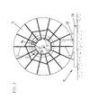
- the more precise structure of the radial struts 6, 7 is shown in the figure 2 can be seen. From this figure it can also be seen that in addition to the described radial struts 6, 7 along the entire outer circumferential surface of the central body 3 radially protruding Radial struts are arranged. Between 2 in Radial struts lying one above the other as viewed in FIG are the colinear connecting struts to the axis 12 10 and 11 arranged to ensure sufficient stability of the To ensure transport device 1.
- This fastening device in the present case consists of a block that the end fastening part 16 engages behind.
- this block 18 prevents this Kinking of the energy chain 2 when winding and prevented also the heavy stress on the end attachment part 16 through the accumulating energy chain 2.
- the fixing device 15 for preventing the Rolling or a rotation of the transport device 1 exists essentially from one that can be placed on a surface Base on which a beam 20 with an arcuate recess 21 is attached.
- the radius of the arcuate recess corresponds essentially to the outer radius of the end plate 5.
- the transport device according to the invention makes it possible for the first time easy to lay even heavy energy chains.
- the transport device is placed over a guide trough unrolled, which take up the energy chain should.
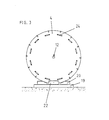
- FIG. 4 is an axial embodiment of the invention Transport device shown in the front view. This embodiment is axially longer than that in FIG. 1 shown, but it has less in the radial direction Dimensions.
- the free end of the cable 25 is initially wound on the section I of the transport device 26.
- the actual energy supply chain is based on Section II wound in alternating layers.
- the end of the cables 27 is wound up on the outer layer of the energy chain 28.
- Figure 5 finally represents a radial embodiment of the Transport device according to the invention in the front view
- the free end of the cable 29 is first on a central body to a lesser extent than the main central body wound.
- the energy chain 31 will on the main central body forming the section II in layers wound. Section II is thus radially spaced apart from the axis of rotation from section I.
- the end of the cables 32 is in turn on the outer layer of the energy chain 31 wound up.
- the transport device is used for transport and storage first deposited on the stands 13, 14. Under the The edges of the end plates 4, 5 are then the base of the pushed fixing device according to the invention. For locking the transport device can then have blocks on the base be placed, which the function of the bar 20 with the fulfill arcuate recess. So it comes down to it to the fact that the fixing device has means for the To prevent rotation of the transport device. Finally one or more flanges 22 between the base and the end plates 4, 5 attached. The transport device can now lifted from the stands 14, 15 and complete with the Fixing device can be moved. This can, for example on a low loader for transport. The stands 14, 15 do not have to be carried for transportation.
Description
Die Erfindung betrifft Transportvorrichtung, die im Wesentlichen die Gestalt einer Kabeltrommel aufweist, auf der eine mit Kabeln oder anderen Leitungen bestückte Energieführungskette aufgewickelt ist, mit einem im Wesentlichen um eine Rotationsachse der Transportvorrichtung angeordneten, vorzugsweise zylindrischen Zentralkörper und einem im Bereich der stirnseitigen Ende des Zentralkörpers angeordneten, sich radial von diesem erstreckenden Endbegrenzungselementen.The invention relates to transport device, which essentially has the shape of a cable drum on which one with Cable or other lines equipped energy chain is wound with a substantially about an axis of rotation arranged the transport device, preferably cylindrical central body and one in the area of the front End of the central body arranged radially from this extending end limiting elements.
Eine derartige Transportvorrichtung ist beispielsweise aus der EP 0 699 616 bekannt.Such a transport device is for example from the EP 0 699 616 known.
Die zu transportierenden Ketten können bereits komplett konfektioniert mit Kabeln, Steckern, Endbefestigungsteilen und Zugentlastungen ausgestattet sein, so daß diese nur noch angeschlossen werden müssen. Derartige Energieführungsketten können eine erhebliche Länge und ein erhebliches Gewicht haben und sind dann im Handling schwierig. Insbesondere das Ablegen einer langen Kette in einer Führungsrinne am Boden oder an einem Kranauslegearm in etwa 10 bis 20 m Höhe ist bei groß ausgebildeten Energieführungsketten mit einer Breite von 10 bis 30 cm nur unter großen Umständen vorzunehmen, da eine solche Kette bis zu 100 m lang sein kann.The chains to be transported can already be completely assembled with cables, plugs, end mounting parts and Strain reliefs must be equipped so that they are only connected Need to become. Such energy chains can be of considerable length and weight and are then difficult to handle. Especially the filing a long chain in a guide trough on the floor or on a crane boom at a height of about 10 to 20 m is large trained energy chains with a width of 10 up to 30 cm only under great circumstances, as a such a chain can be up to 100 m long.
Der Erfindung liegt die Aufgabe zugrunde, das Handling und den Transport von Energieführungsketten zu vereinfachen.The invention is based, the handling and the task Simplify transportation of energy chains.
Erfindungsgemäß wird dieses dadurch gelöst, dass Mittel vorgesehen sind zur Unterteilung des Raumes zwischen den Endbegrenzungselementen in mindestens einem ersten Abschnitt, in dem aus einem Ende der Energieführungskette herausragenden Leitungen aufgewickelt sind, und einem zweiten Abschnitt, in dem die eigentliche Energieführungskette aufgewickelt ist. According to the invention, this is achieved by providing means are used to divide the space between the end limitation elements in at least a first section, in the one that sticks out of one end of the energy chain Lines are wound, and a second section, in on which the actual energy supply chain is wound.
Der Zentralkörper ist vorzugsweise als kreiszylindrischer Hohlkörper ausgebildet, um ein einfaches Aufwickeln zu gewährleisten und das Auftreten eines Polygoneffektes weitestgehend zu verhindern. Die Systemkette ist in dem Zwischenraum zwischen den beiden Endbegrenzungselementen durch Rotation des Zentralkörpers aufwickelbar. Der Zwischenraum zwischen den Endbegrenzungselementen kann je nach Bedarf breiter oder schmaler ausgestaltet sein. Die Innenbreite der Trommel kann z.B. etwa der Kettenbreite entsprechen, was zu einer radialen Aufwicklung, aber gleichzeitig einer Trommel von geringen Längsabmaßen führt. Diese Version wird als radiale Ausführungsform bezeichnet. Alternativ kann die Innenbreite der Trommel ein Vielfaches der Kettenbreite betragen. Bei dieser Ausgestaltung kann die Aufwicklung in einer Lage oder mehreren Lagen erfolgen. Dieses führt im Vergleich zur ersten Ausführungsform zu einer breiteren Trommel, die aber dafür geringe radiale Ausmessungen aufweist. Diese zweite Version wird im folgenden als axiale Ausführungsform bezeichnet.The central body is preferably a circular cylindrical Hollow body designed to ensure easy winding and the occurrence of a polygon effect as far as possible to prevent. The system chain is in the gap between the two end limiting elements by rotating the Central body can be wound up. The space between the End limiting elements can be wider or wider as needed be made narrower. The inside width of the drum can e.g. correspond approximately to the chain width, resulting in a radial Winding, but at the same time a drum of low Longitudinal dimensions leads. This version is called the radial embodiment designated. Alternatively, the inside width of the Drum a multiple of the chain width. At this The winding can be designed in one layer or several Layers. This leads in comparison to the first embodiment to a wider drum, but a small one for that has radial dimensions. This second version will be released in hereinafter referred to as the axial embodiment.
Es liegt auch im Rahmen der Erfindung, daß die Endbegrenzungselemente verschiebbar auf dem Zentralkörper angeordnet sind, um die Transportvorrichtung entsprechend den Bedürfnissen für unterschiedlich breite Kettensysteme bzw. Ketten verwenden zu können.It is also within the scope of the invention that the end limiting elements slidably arranged on the central body are to the transport device according to needs for chain systems or chains of different widths to be able to use.
Der Zentralkörper muß nicht notwendigerweise ein geschlossener Körper sein, sondern kann auch aus mehreren nebeneinander angeordneten Stangen oder Stegen bestehen.The central body does not necessarily have to be a closed one Body, but can also consist of several side by side arranged bars or webs exist.
Die Endbegrenzungselemente sind vorzugsweise als kreisförmige Endscheiben ausgebildet, da dieses ein besonders einfaches Abrollen der Kettensysteme von der Transportvorrichtung ermöglicht. Die Transportvorrichtung kann zum Aufwickeln und Abwickeln der Systemkette dann einfach gerollt werden. Zum Verbessern des Handlings der Transportvorrichtung sind an der in Einbaulage äußeren Seite der Endscheiben Handgriffe vorgesehen, mit Hilfe derer Benutzer die Transportvorrichtung abund aufrollen können.The end limit elements are preferably circular End plates formed, as this is a particularly simple Unrolling the chain systems from the transport device allows. The transport device can be used for winding and Unwinding the system chain can then simply be rolled. To the Improve the handling of the transport device are on the Handles provided in the installed position on the outer side of the end plates, with the help of which the transport device from time to time can roll up.
Es kommt häufig vor, daß derartige Systemketten aus den Enden der eigentlichen Energieführungskette herausragende Leitungen aufweisen. Auch diese Leitungen müssen auf die Transportvorrichtung aufgewickelt werden. Dabei ist zu beachten, daß insbesondere zu Beginn des Aufwickelns keine scharfen Übergänge entstehen, die zu einem Abknicken der herausragenden Leitungen und zu deren Beschädigung führen würden. Aus diesem Grund sind in dem Zwischenraum zwischen den Endbegrenzungselementen bzw. Endscheiben die Unterteilungsmittel angeordnet. Durch diese Unterteilungsmittel wird sichergestellt, daß die Energieführungskette und die Enden in definierten Bereichen aufgewickelt werden können, die durch die Unterteilungsmittel gebildet werden.It often happens that such system chains come from the ends outstanding cables in the actual energy supply chain exhibit. These lines must also be on the transport device be wound up. It should be noted, that especially at the beginning of the winding up no sharp ones Transitions arise that cause the outstanding ones to snap Lines and lead to their damage. For this The reason is in the space between the end limiting elements or end disks the subdivision means arranged. These subdivision means ensure that the energy chain and the ends in defined Areas that can be wound up by the Subdivision means are formed.
Es existieren grundsätzlich zwei unterschiedliche Möglichkeiten der Unterteilung. Zum einen die axiale Ausführung, wobei die Unterteilung durch kreisförmige Unterteilungsscheiben erfolgt, zwischen denen Verbindungsstreben aufgespannt sind. Die Unterteilungsscheiben oder Streben erstrecken sich radial von dem Zentralkörper weg, um den zwischen den Endscheiben vorgesehenen Raum in - von der Seite her gesehen - scheibenförmige Abschnitte aufzuteilen, in denen die Kabel und Energieführungskette definiert aufgewickelt werden können.There are basically two different options the subdivision. Firstly, the axial design, the division by circular dividing discs takes place between which struts are spanned are. The dividing washers or struts extend radially away from the central body to the between the End disks provided space in - seen from the side - to divide disc-shaped sections in which the cables and Energy supply chain can be wound defined.
Alternativ zu den Unterteilungsscheiben können an dem Zentralkörper befestigte Streben vorgesehen sein, die sich radial von dem Zentralkörper erstrecken. Zwischen diesen Streben und/oder den Endscheiben werden dann Verbindungsstreben angeordnet, die in Einbaulage vorzugsweise kolinear zur Rotationsachse der Transportvorrichtung verlaufen. Auf diese Verbindungsstreben können Energieführungsketten oder Kabel aufgewickelt werden. Die Verbindungsstreben sind an den Radialstreben versetzbar befestigt, um die Transportvorrichtung je nach Einsatzzweck umgestalten zu können.As an alternative to the dividing disks, you can use the central body fixed struts are provided, which are radial extend from the central body. Between these struts and / or the end disks, connecting struts are then arranged, in the installed position, preferably colinear with the axis of rotation of the transport device. On these connecting struts can be wrapped in energy chains or cables become. The connecting struts are on the radial struts movably attached to the transport device to be able to remodel depending on the application.
Bei der radialen Ausführungsform wird die Energieführungskette oder das Kabel zunächst auf den Zentralkörper aufgewickelt. Zur Bildung eines zweiten Abschnitts werden zwischen den Radialstreben Verbindungsstreben bzw. Verbindungselemente eingesetzt, die wiederum im wesentlichen kolinear zur Rotationsachse der Transportvorrichtung verlaufen. Die weitere Aufwicklung der Energieführungskette erfolgt auf den Verbindungsstreben. Bei der radialen Ausführungsform werden also radial voneinander beabstandete Abschnitte beim Aufwickeln der Energieführungskette durch Einsetzen der Verbindungsstreben erzeugt. Je nach Wunsch können durch Einsetzen weiterer Verbindungsstreben radial beabstandet weitere Abschnitte ausgebildet werden.In the radial embodiment, the energy chain or the cable is first wound onto the central body. To form a second section between the radial struts Connecting struts or connecting elements used, which in turn are essentially colinear with the axis of rotation of the transport device. The further one The energy supply chain is wound on the connecting struts. So in the radial embodiment radially spaced sections when winding the Energy chain by inserting the connecting struts generated. Depending on your wishes, you can insert additional connecting struts formed radially spaced further sections become.
Um eine genaue Fixierung der Energieführungskette und einer Beschädigung der Endbefestigungsteile zu verhindern, ist es vorteilhaft, eine Befestigungsvorrichtung für die Energieführungskette oder das Endbefestigungsteil an der Transportvorrichtung vorzusehen. Üblicherweise ist diese Befestigungsvorrichtung an den Zentralkörper oder den seitlichen Endbegrenzungselementen angeordnet.To an exact fixation of the energy chain and one It is to prevent damage to the end fasteners advantageous, a fastening device for the energy chain or the end fastening part on the transport device provided. This is usually a fastening device to the central body or the side End limiting elements arranged.
Die Transportvorrichtung kann mit einer Achse versehen sein, die koaxial zur Rotationsachse durch den Zentralkörper verläuft. Die Achse kann sowohl fest eingesetzt als auch lösbar einsetzbar ausgebildet sein. An den seitlich aus der Transportvorrichtung herausragenden Enden der Achse kann die Transportvorrichtung für den Transport angehoben werden. Dieses erfolgt beispielsweise durch die Achse umschließende Ketten, welche durch einen Kran angehoben werden. Um eine Drehung der Transportvorrichtung beim Anheben zu verhindern, sind zwischen den Ketten oder dem Seil auf die Achse aufsetzbare Bremsen angeordnet.The transport device can be provided with an axis, which runs coaxially to the axis of rotation through the central body. The axis can be used both fixed and detachable be usable. On the side of the transport device protruding ends of the axis can be the transport device be lifted for transportation. This takes place, for example, by chains enclosing the axis, which are lifted by a crane. To turn the To prevent transport device when lifting are between Brakes that can be placed on the chain or rope on the axle arranged.
Die Achse muß nicht als durchgehende Achse ausgebildet sein. Es ist auch möglich, zylindrische Stäbe aus Vollmaterial auf der Außenseite der Endscheiben zu befestigen. The axis does not have to be designed as a continuous axis. It is also possible to have cylindrical rods made of solid material the outside of the end plates.
Die Erfindung ist in der Zeichnung anhand eines bevorzugten Ausführungsbeispiels veranschaulicht. Es zeigen:
- Figur 1:
- eine Frontansicht einer axialen Ausführungsform der erfindungsgemäßen Transportvorrichtung mit aufgewickelter Energieführungskette,
- Figur 2:
- eine Seitenansicht entlang der Linie II-II gemäß Figur 1,
- Figur 3:
- eine Stirnansicht entlang des Pfeils III gemäß Figur 1 ohne Ständer,
- Figur 4:
- eine alternative Variante der axialen Ausführungsform der Transportvorrichtung und
- Figur 5:
- eine Variante der radialen Ausführungsform der erfindungsgemäßen Transportvorrichtung.
- Figure 1:
- 2 shows a front view of an axial embodiment of the transport device according to the invention with a coiled energy chain,
- Figure 2:
- 2 shows a side view along the line II-II according to FIG. 1,
- Figure 3:
- 3 shows an end view along arrow III according to FIG. 1 without stand,
- Figure 4:
- an alternative variant of the axial embodiment of the transport device and
- Figure 5:
- a variant of the radial embodiment of the transport device according to the invention.
Die Transportvorrichtung ist in ihrer Gesamtheit mit 1 bezeichnet und die Energieführungskette mit 2.The transport device is designated 1 in its entirety and the energy chain with 2.
Die Transportvorrichtung 1 hat die Gestalt einer sehr groß
dimensionierten Kabeltrommel mit einem koaxial zur Rotationsachse
der Transportvorrichtung angeordneten, zylindrischen
Zentralkörper 3, auf den die Energieführungskette 2, zumindest
teilweise, aufwickelbar ist. The transport device 1 has the shape of a very large
dimensioned cable drum with a coaxial to the axis of rotation
arranged in the transport device, cylindrical
Im Bereich der stirnseitigen Enden des Zentralkörpers 3 sind
kreisrunde Endscheiben 4 und 5 angeordnet. Zur Unterteilung
des Raumes zwischen den Endscheiben in drei Abschnitte sind in
Längsrichtung von den Endscheiben beabstandete Radialstreben
6, 7, 8, 9 an dem Zentralkörper 3 befestigt. Zwischen den
Radialstreben 6, 7, 8, 9 sind Verbindungsstreben befestigt,
welche auch die Radialstreben 6, 7, 8, 9 voneinander beabstanden
und stabilisieren. Die Radialstreben 6, 7, 8, 9 und die
Verbindungsstreben 10, 11 sind vorliegend als C-Profile aus
Stahl gefertigt. Die Verbindungsstreben 10, 11 sind axial
entlang der Längsachse der Radialstreben 6, 7, 8, 9 verschiebbar
und können in jeder beliebigen Position an diesen fixiert
werden. Auch die Radialstreben können in axialer Richtung an
beliebigen Stellen auf dem Zentralkörper angeordnet sein.In the area of the front ends of the
Durch die zentrale Rotationsachse der Transportvorrichtung
verläuft eine in ihrer Gesamtheit mit 12 bezeichnete Achse,
die drehfest mit den Endscheiben 4 und 5 verbunden ist. Die
freien Enden der Achse 12 sitzen in Ruhelage auf Ständern 13
und 14 auf.Through the central axis of rotation of the transport device
runs an axis designated in its entirety with 12,
which is rotatably connected to the
Die Transportvorrichtung ist auf einer erfindungsgemäßen Fixiervorrichtung angeordnet, die in ihrer Gesamtheit mit 15 bezeichnet ist.The transport device is on a fixing device according to the invention arranged in their entirety with 15 is designated.
Für das Auf- und Abwickeln werden Ketten oder Seile an den
freien Enden der Achse 12 befestigt und die gesamte Transportvorrichtung
wird mit einem Kran über die Ketten angehoben.
Beim Anheben wird die Transportvorrichtung 1 von der Fixiervorrichtung
abgehoben, so daß sich die Transportvorrichtung 1
frei drehen kann. Die Energieführungskette 2 wird nun auf die
Transportvorrichtung aufgewickelt. Um ein Beschädigen der
Energieführungskette 2 zu verhindern, wird diese definiert in
den drei Abschnitten zwischen den Endscheiben 4 und 5 aufgewickelt.
Zunächst werden die freien Enden der Kabel 23 der
Energieführungskette 2 in den mit I gekennzeichneten Abschnitt
aufgerollt. Kurz vor Beginn der eigentlichen Energieführungskette
2 werden die Kabel durch den Abschnitt II in den Abschnitt
III umgelenkt. Das Aufwickeln der eigentlichen Glieder
der Energieführungskette 2 erfolgt in Abschnitt III. Durch den
Übergang der Kabel von dem Abschnitt I in den Abschnitt III
wird verhindert, daß die Kabel abrupt abgeknickt und beschädigt
werden.Chains or ropes are attached to the for winding and unwinding
Free ends of the
Nachdem die Glieder der Energieführungskette 2 auf die Transportvorrichtung
1 aufgewickelt worden sind, werden die am
anderen Ende der Energieführungskette gelegenen freien Kabel
auf die Verbindungssstreben 10, 11 in dem Abschnitt II aufgewickelt.
Durch die Verbindungsstreben 10 und 11 müssen die
Kabelenden nicht wieder ganz bis auf den Zentralkörper heruntergeführt
werden und werden im Bereich des radialen Außenrandes
an leicht zugänglicher Stelle aufgewickelt.After the links of the
Außenseitig an den Endscheiben 4 und 5 sind Griffe für ein
leichteres Handling vorgesehen. Diese Griffe sind insbesondere
aus Figur 3 zu entnehmen.On the outside of the
Der genauere Aufbau der Radialstreben 6, 7 ist aus der Figur
2 ersichtlich. Aus dieser Figur ist auch zu entnehmen, daß
neben den beschriebenen Radialstreben 6, 7 entlang der gesamten
äußeren Mantelfläche des Zentralkörpers 3 radial abstehende
Radialstreben angeordnet sind. Zwischen jeweils 2 in
Blickrichtung der Figur 2 übereinander liegenden Radialstreben
sind die kolinear zur Achse 12 verlaufenden Verbindungsstreben
10 und 11 angeordnet, um eine ausreichende Stabilität der
Transportvorrichtung 1 zu gewährleisten.The more precise structure of the radial struts 6, 7 is shown in the figure
2 can be seen. From this figure it can also be seen that
in addition to the described
Zur besseren Fixierung der Endbefestigungsteile 16 von Energieführungsketten
ist an dem Zentralkörper 3 eine Befestigungsvorrichtung
15 vorgesehen. Diese Befestigungsvorrichtung
besteht vorliegend aus einem Klotz, den das Endbefestigungsteil
16 hintergreift.For better fixation of the
In geringem Abstand vor dem Endbefestigungsteil 16 bzw. der
Befestigungsvorrichtung ist ein weiterer Klotz 18 drehfest mit
dem Zentralkörper 3 verbunden. Dieser Klotz 18 verhindert das
Abknicken der Energieführungskette 2 beim Aufwickeln und verhindert
zudem die starke Beanspruchung des Endbefestigungsteiles
16 durch die auflaufende Energieführungskette 2.At a short distance from the
Die Fixiervorrichtung 15 zum Verhindern des
Rollens oder einer Rotation der Transportvorrichtung 1 besteht
im wesentlichen aus einem auf einen Untergrund aufsetzbaren
Sockel, auf dem ein Balken 20 mit einer bogenförmigen Ausnehmung
21 befestigt ist. Der Radius der bogenförmigen Ausnehmung
entspricht im wesentlichen dem Außenradius der Endscheibe
5. Wenn die Transportvorrichtung 1 in die Ausnehmung
21 des Sockels 19 eingesetzt ist, verhindert die Fixiervorrichtung
15 eine Rotation der Transportvorrichtung 1. Eine
noch bessere Fixierung wird erreicht, wenn die Endscheiben 5
und 6 mit dem Sockel 19 über einen Flansch 22 verbunden werden.The fixing
Die erfindungsgemäße Transportvorrichtung ermöglicht es erstmalig, auch schwere Energieführungsketten einfach zu verlegen. Zu diesem Zweck wird die Transportvorrichtung über einer Führungsrinne abgerollt, welche die Energieführungskette aufnehmen soll.The transport device according to the invention makes it possible for the first time easy to lay even heavy energy chains. For this purpose, the transport device is placed over a guide trough unrolled, which take up the energy chain should.
Durch Anheben der Transportvorrichtung mit einem Kran können
die auf der Transportvorrichtung aufgewickelten Energieführungsketten
einfach an einem Kranausleger in größeren Höhen
befestigt werden. Durch die Befestigung mit dem Flansch kann
die Fixiervorrichtung 15 zusammen mit der Transportvorrichtung
von dem Kran angehoben werden.By lifting the transport device with a crane
the energy supply chains wound on the transport device
simply on a crane boom at higher heights
be attached. By fastening with the flange
the fixing
In Figur 4 ist eine axiale Ausführungsform der erfindungsgemäßen
Transportvorrichtung in der Frontansicht dargestellt.
Diese Ausführungsform ist axial länger als die in Figur 1
dargestellte, dafür weist sie aber in radialer Richtung geringere
Ausmaße auf. Das freie Ende der Kabel 25 wird zunächst
auf den Abschnitt I der Transportvorrichtung 26 aufgewickelt.
Die eigentliche Energieführungskette wird auf den Abschnitt II
in alternierenden Lagen aufgewickelt. Das Ende der Kabel 27
wird auf die äußere Lage der Energieführungskette 28 aufgewikkelt.In Figure 4 is an axial embodiment of the invention
Transport device shown in the front view.
This embodiment is axially longer than that in FIG. 1
shown, but it has less in the radial direction
Dimensions. The free end of the cable 25 is initially
wound on the section I of the transport device 26.
The actual energy supply chain is based on Section II
wound in alternating layers. The end of the
Figur 5 stellt schließlich eine radiale Ausführungsform der
erfindungsgemäßen Transportvorrichtung in der Frontansicht
dar. Das freie Ende der Kabel 29 wird zunächst auf einen Zentralkörper
mit geringerem umfänglichen Ausmaß als der Hauptzentralkörper
aufgewickelt. Die Energieführungskette 31 wird
auf den den Abschnitt II bildenden Hauptzentralkörper in Lagen
aufgewickelt. Damit ist der Abschnitt II radial beabstandet
von der Rotationsachse vom der Abschnitt I. Das Ende der Kabel
32 ist wiederum auf die äußere Lage der Energieführungskette
31 aufgewickelt.Figure 5 finally represents a radial embodiment of the
Transport device according to the invention in the front view
The free end of the
Je nach Anwendungsfall sind verschiedene Ausführungsformen der axialen und radialen Transportvorrichtung gestaltbar. Kombinationen der beiden Varianten sind ebenfalls möglich.Depending on the application, different embodiments of the axial and radial transport device can be designed. combinations the two variants are also possible.
Für den Transport und die Lagerung wird die Transportvorrichtung
zunächst auf den Ständern 13, 14 abgesetzt. Unter die
Umfangsränder der Endscheiben 4, 5 wird dann der Sockel der
erfindungsgemäßen Fixiervorrichtung geschoben. Zur Arretierung
der Transportvorrichtung können dann Klötze auf den Sockel
aufgesetzt werden, welche die Funktion des Balkens 20 mit der
bogenförmigen Ausnehmung erfüllen. Es kommt demnach wesentlich
darauf an, daß die Fixiervorrichtung Mittel aufweist, um die
Rotation der Transportvorrichtung zu verhindern. Schließlich
werden ein oder mehrere Flansche 22 zwischen dem Sockel und
den Endscheiben 4, 5 befestigt. Die Transportvorrichtung kann
nun von den Ständern 14, 15 abgehoben und komplett mit der
Fixiervorrichtung versetzt werden. Dieses kann beispielsweise
auf einen Tieflader für den Transport erfolgen. Die Ständer
14, 15 müssen für den Transport nicht mitgeführt werden. The transport device is used for transport and storage
first deposited on the
- 11
- Transportvorrichtungtransport device
- 22
- EnergieführungskettePower supply chain
- 33
- Zentralkörpercentral body
- 44
- Endscheibeend disk
- 55
- Endscheibeend disk
- 6, 7, 8, 96, 7, 8, 9
- Radialstreberadial strut
- 10, 1110, 11
- Verbindungsstrebeconnecting strut
- 1212
- Achseaxis
- 13, 1413, 14
- Ständerstand
- 1515
- Fixiervorrichtungfixing
- 1616
- Endbefestigungsteileend mounting
- 1717
- Klotzblock
- 1818
- Klotzblock
- 1919
- Sockelbase
- 2020
- Balkenbar
- 2121
- Ausnehmungrecess
- 2222
- Flanschflange
- 2323
- Kabelelectric wire
- 2424
- GriffHandle
- 2525
- Kabelelectric wire
- 2626
- Transportvorrichtungtransport device
- 2727
- Kabelelectric wire
- 2828
- EnergieführungskettePower supply chain
- 2929
- Kabelelectric wire
- 3030
- Transportvorrichtungtransport device
- 3131
- EnergieführungskettePower supply chain
- 3232
- Kabelelectric wire
Claims (8)
- Transport device (1, 26, 30) essentially having the form of a cable drum that is wound up with an energy guiding chain (2) fitted with cables or other lines with a preferably cylindrical central core (3) essentially mounted about a rotational axis of the transport device, with end elements located on the face ends of the central core and extending radially from it, and with means for dividing the space between the end elements into at least one first section in which the cables (25, 29) protruding from an end of the energy guiding chain (2) are wound up, and into a second section in which the energy guiding chain as such (28, 31) is wound up.
- Transport device (1, 26, 30) as per Claim 1, characterised in that the end elements are designed as circular end disks (4,5).
- Transport device (1, 26, 30) as per Claim 1 or 2, characterised in that the means for dividing comprise radial struts (6, 7, 8, 9) extending radially away from the central core (3), of which at least two are mounted on the central core (3) in line with one another as a pair, and that between aligned radial struts (8, 9 and/or 6, 7) connecting struts (10 and/or 11) are mounted, which are essentially colinear to the rotational axis and on which the lines protruding from an end of the energy guiding chain or the energy guiding chain as such (2) are wound up.
- Transport device (1) as per Claim 3, characterised in that the space between the end elements is divided into three sections (I, II, III) by the radial struts (6, 7, 8, 9), wherein the cables protruding from an end of the energy guiding chain are rolled up in a section (I) bordering on one end element, the energy guiding chain as such is wound up in a section (III) bordering on the other end element, the cables running through the intermediate section (II), and the cables protruding from the other end of the energy guiding chain (2) are wound up on the connecting struts (10, 11) mounted between the radial struts (6, 7, 8, 9) in the intermediate section (II).
- Transport device (26) as per Claim 1 or 2, characterised in that the means for dividing the space between the end elements form two axially separated sections (I, II), wherein the cables (25) protruding from one end of the energy guiding chain (2) are wound up in the first section (I), the energy guiding chain as such (28) is wound up in the other section (II) and wherein the cables (27) protruding from the other end of the energy guiding chain (2) are wound up on the outer layer of the energy guiding chain (28).
- Transport device (30) as per Claim 1 or 2, characterised in that the central core includes a section (I) with a smaller circumference and another section (II) with a bigger circumference, wherein the cables protruding from one end of the energy guiding chain are wound up in the section (I) with the smaller circumference, the energy guiding chain (31) is wound up in the section (II) with the bigger circumference, and the cables (32) protruding from the other end of the energy guiding chain are wound up on the outer layer of the energy guiding chain (31).
- Transport device (1, 26, 30) as per one of Claims 1 to 6, characterised in that a fastening device (17) for an end of the energy guiding chain (2), preferably equipped with an end mounting element (16), is provided on the central core (3) or the end elements.
- Transport device (1, 26, 30) as per one of Claims 1 to 7, characterised by a shaft (12) running coaxially to the rotational axis through the central core (3).
Applications Claiming Priority (3)
| Application Number | Priority Date | Filing Date | Title |
|---|---|---|---|
| DE29907445U | 1999-04-19 | ||
| DE29907445U DE29907445U1 (en) | 1999-04-19 | 1999-04-19 | Transport device |
| PCT/DE2000/001147 WO2000063585A1 (en) | 1999-04-19 | 2000-04-13 | Transporting device |
Publications (2)
| Publication Number | Publication Date |
|---|---|
| EP1171725A1 EP1171725A1 (en) | 2002-01-16 |
| EP1171725B1 true EP1171725B1 (en) | 2003-10-29 |
Family
ID=8072758
Family Applications (1)
| Application Number | Title | Priority Date | Filing Date |
|---|---|---|---|
| EP00934904A Expired - Lifetime EP1171725B1 (en) | 1999-04-19 | 2000-04-13 | Transporting device |
Country Status (9)
| Country | Link |
|---|---|
| US (1) | US6554219B2 (en) |
| EP (1) | EP1171725B1 (en) |
| JP (1) | JP3487590B2 (en) |
| KR (1) | KR100411360B1 (en) |
| CN (1) | CN1114051C (en) |
| AU (1) | AU5059700A (en) |
| DE (2) | DE29907445U1 (en) |
| TW (1) | TW425463B (en) |
| WO (1) | WO2000063585A1 (en) |
Cited By (1)
| Publication number | Priority date | Publication date | Assignee | Title |
|---|---|---|---|---|
| DE202014105940U1 (en) | 2014-12-09 | 2015-01-07 | Igus Gmbh | Reel device for at least one line and supply device with this reel device |
Families Citing this family (8)
| Publication number | Priority date | Publication date | Assignee | Title |
|---|---|---|---|---|
| NL1030276C2 (en) * | 2005-10-26 | 2007-04-27 | Priva Holding B V | Link chain and drum assembly for use in cultivation area, has drum provided for link chain that contains adjacent hinged links that skip in relation to each other at axis offset distance, where chain extends from drum according to direction |
| DE102006026854B3 (en) * | 2006-06-09 | 2007-11-08 | Wampfler Aktiengesellschaft | Energy transmission chain system assembling method, involves transporting transportation unit as whole to place of installation of system, and placing/removing section of guiding channel in/from framework during final assembly of system |
| DE102010006917A1 (en) | 2010-02-04 | 2011-08-04 | ekd gelenkrohr GmbH, 40699 | Transport device for e.g. small energy guiding chain, has bars attached at middle section of profile rods and connecting one of profile rods of side part with another one of rods of another side part, so that side parts are connected |
| JP5794583B2 (en) * | 2012-05-31 | 2015-10-14 | 旭精機工業株式会社 | Wire forming machine |
| CN103236672A (en) * | 2013-04-28 | 2013-08-07 | 国家电网公司 | Transport and pay-off vehicle |
| RU2556869C2 (en) * | 2013-09-11 | 2015-07-20 | Открытое акционерное общество "Ракетно-космическая корпорация "Энергия" имени С.П. Королева" | Device for transportation and routing of cables on outer surface of space object by astronaut wearing space suit and operating method of device |
| RU2615466C2 (en) * | 2015-05-20 | 2017-04-04 | Открытое акционерное общество "Ракетно-космическая корпорация "Энергия" имени С.П. Королева" | Device for laying flexible element extended along length in space conditions and operation method thereof |
| CN109534102B (en) * | 2018-12-20 | 2021-03-16 | 国网北京市电力公司 | Cable reel |
Family Cites Families (28)
| Publication number | Priority date | Publication date | Assignee | Title |
|---|---|---|---|---|
| US1621714A (en) * | 1926-02-12 | 1927-03-22 | Joseph G Dyer | Bull-wheel attachment |
| DE538468C (en) * | 1930-04-29 | 1931-11-13 | Sueddeutsche Kabelwerke Zweign | Cable drum with a winding space divided by walls |
| US1909277A (en) * | 1931-03-30 | 1933-05-16 | James Heddon S Sons | Wound spool |
| US2219201A (en) * | 1939-02-21 | 1940-10-22 | Frank L Smith | Reel for hose, cables, etc. |
| DE1208146B (en) | 1962-08-02 | 1965-12-30 | Sms Samesreuther Mueller Schus | Device on winding drums |
| DE1449666B2 (en) | 1962-11-03 | 1970-09-17 | Hin, John, Pearnhead, Lancaster (Gro übri tannien) | heavy cable drum |
| US3130929A (en) * | 1963-01-28 | 1964-04-28 | Anaconda Wire & Cable Co | Method of reeling and unreeling electric cable |
| GB1217332A (en) * | 1967-03-17 | 1970-12-31 | Plessey Co Ltd | Improvements in or relating to reeling apparatus |
| US3539123A (en) * | 1968-07-11 | 1970-11-10 | Western Electric Co | Winding drum for continuous linear conductor |
| US3837590A (en) * | 1972-06-26 | 1974-09-24 | Johns Manville | Cable reel assembly |
| US3854017A (en) * | 1972-12-18 | 1974-12-10 | W Crim | Telephone and electric cord reel |
| DE7729407U1 (en) | 1977-09-22 | 1978-01-05 | Odenwaldwerke Rittersbach Kern & Grosskinsky Gmbh, 6957 Elztal | HOSE REEL |
| US4345724A (en) | 1980-06-23 | 1982-08-24 | The Anaconda Company | Lightweight reel |
| US4667896A (en) * | 1986-06-05 | 1987-05-26 | Siecor Corporation | Three flange cable spool |
| DE4019513A1 (en) * | 1990-06-19 | 1992-01-09 | Siemens Ag | DEVICE WITH A DEVICE FOR RECEIVING AN ELECTRICAL LEAD |
| US5113976A (en) * | 1990-10-29 | 1992-05-19 | Noakes Larry R | Reel chock with set screws for flange engagement |
| JPH04209172A (en) * | 1990-11-30 | 1992-07-30 | Showa Electric Wire & Cable Co Ltd | Emergency aid drum |
| US5322228A (en) * | 1991-05-20 | 1994-06-21 | Sumitomo Electric Industries, Inc. | Method for screening optical fiber and apparatus for carrying out method |
| DE4119211C1 (en) * | 1991-06-11 | 1992-12-17 | Bauer Spezialtiefbau Gmbh, 8898 Schrobenhausen, De | |
| DE9112515U1 (en) | 1991-10-08 | 1992-03-19 | Katimex Cielker Gmbh, 5000 Koeln, De | |
| US5279469A (en) * | 1991-12-20 | 1994-01-18 | Hillmar Industries Ltd. | Cable winding apparatus and method |
| US5215279A (en) * | 1991-12-20 | 1993-06-01 | Hillmar Industries Ltd. | Cable reel with off-set spokes |
| DE4426598C1 (en) * | 1994-07-27 | 1995-12-21 | Bauer Spezialtiefbau | Hose chain with U=shaped links |
| DE4431159A1 (en) * | 1994-09-01 | 1996-03-07 | Rheydt Kabelwerk Ag | Bicameral coil |
| GB9500954D0 (en) * | 1995-01-18 | 1995-03-08 | Head Philip | A method of accessing a sub sea oil well and apparatus therefor |
| DE19536722A1 (en) * | 1995-09-30 | 1997-04-03 | Kabelmat Hans Deisenberger Gmb | Stand for supporting reel, especially cable reel |
| FR2744710B1 (en) * | 1996-02-13 | 1998-05-22 | Alphacan Sa | REEL FOR THE RUNNING OF CROWNS OF TUBES, PROFILES OR THE LIKE, PARTICULARLY IN PLASTIC MATERIAL |
| US6113023A (en) * | 1997-02-24 | 2000-09-05 | Piller-Gmbh | Take-up device |
-
1999
- 1999-04-19 DE DE29907445U patent/DE29907445U1/en not_active Expired - Lifetime
-
2000
- 2000-04-13 EP EP00934904A patent/EP1171725B1/en not_active Expired - Lifetime
- 2000-04-13 KR KR10-2001-7013273A patent/KR100411360B1/en not_active IP Right Cessation
- 2000-04-13 JP JP2000612645A patent/JP3487590B2/en not_active Expired - Fee Related
- 2000-04-13 AU AU50597/00A patent/AU5059700A/en not_active Abandoned
- 2000-04-13 WO PCT/DE2000/001147 patent/WO2000063585A1/en active IP Right Grant
- 2000-04-13 CN CN00806435A patent/CN1114051C/en not_active Expired - Fee Related
- 2000-04-13 DE DE50004258T patent/DE50004258D1/en not_active Expired - Lifetime
- 2000-04-18 TW TW089107229A patent/TW425463B/en not_active IP Right Cessation
-
2001
- 2001-10-17 US US09/978,648 patent/US6554219B2/en not_active Expired - Lifetime
Cited By (1)
| Publication number | Priority date | Publication date | Assignee | Title |
|---|---|---|---|---|
| DE202014105940U1 (en) | 2014-12-09 | 2015-01-07 | Igus Gmbh | Reel device for at least one line and supply device with this reel device |
Also Published As
| Publication number | Publication date |
|---|---|
| JP2002542135A (en) | 2002-12-10 |
| DE50004258D1 (en) | 2003-12-04 |
| US6554219B2 (en) | 2003-04-29 |
| TW425463B (en) | 2001-03-11 |
| AU5059700A (en) | 2000-11-02 |
| JP3487590B2 (en) | 2004-01-19 |
| EP1171725A1 (en) | 2002-01-16 |
| KR100411360B1 (en) | 2003-12-18 |
| CN1347483A (en) | 2002-05-01 |
| DE29907445U1 (en) | 1999-08-05 |
| CN1114051C (en) | 2003-07-09 |
| KR20020005690A (en) | 2002-01-17 |
| US20020060262A1 (en) | 2002-05-23 |
| WO2000063585A1 (en) | 2000-10-26 |
| WO2000063585B1 (en) | 2001-02-01 |
Similar Documents
| Publication | Publication Date | Title |
|---|---|---|
| EP0503315B1 (en) | Winding device for winding and unwinding a cable | |
| DE3512589C2 (en) | ||
| EP0518292B1 (en) | Hose piping with several parallel hoses | |
| EP0628013A1 (en) | Bobbin for receiving elongated winding material | |
| EP1171725B1 (en) | Transporting device | |
| DE60222689T2 (en) | DEVICE FOR FACILITATING THE HANDLING OF COILS OR HASPS BY ROLLERS AND PANS ON THE GROUND | |
| DE2439488A1 (en) | Collapsible winch drum - has number of drum surface forming sections axially and circumferentially clamped between side members | |
| EP0520256B1 (en) | Cable drum | |
| DE1456492A1 (en) | Hanging material handling device | |
| DE6942737U (en) | SUPPORTING AND TRANSPORT DEVICE FOR CABLE REELS | |
| EP2829333B1 (en) | Tape reel arrangement for winding and/or unwinding a metal strip | |
| DE2340154A1 (en) | COMPENSATION SYSTEM FOR HIGH PERFORMANCE CRANES | |
| WO2019202089A1 (en) | Elevator-rope reel, elevator system, and method for initiating a rope-like compensation weight when extending a climbing elevator | |
| DE3119040A1 (en) | NETBED | |
| EP3480150B1 (en) | Coil body, in particular a spool bobbin | |
| DE2110408C2 (en) | Coil spring driven winding device | |
| DE1449666B2 (en) | heavy cable drum | |
| DE1449666C (en) | Heavy cable drum | |
| DE19817933A1 (en) | Winch rope guide for aligning rope lines | |
| DE2107851B2 (en) | DEVICE FOR WINDING AND TRANSPORTING FLEXIBLE CABLES OR DGL | |
| DE1515900C (en) | Cable drum | |
| DE202022100378U1 (en) | hose reel | |
| DE1481875C (en) | Reel for balancing loads | |
| DE19638834C2 (en) | Rope winder for the drum of a hoist | |
| DE4344218A1 (en) | Paying out device for electrical or optical fibre cable |
Legal Events
| Date | Code | Title | Description |
|---|---|---|---|
| PUAI | Public reference made under article 153(3) epc to a published international application that has entered the european phase |
Free format text: ORIGINAL CODE: 0009012 |
|
| 17P | Request for examination filed |
Effective date: 20011012 |
|
| AK | Designated contracting states |
Kind code of ref document: A1 Designated state(s): AT BE CH CY DE DK ES FI FR GB GR IE IT LI LU MC NL PT SE |
|
| AX | Request for extension of the european patent |
Free format text: AL;LT;LV;MK;RO;SI |
|
| GRAH | Despatch of communication of intention to grant a patent |
Free format text: ORIGINAL CODE: EPIDOS IGRA |
|
| GRAS | Grant fee paid |
Free format text: ORIGINAL CODE: EPIDOSNIGR3 |
|
| GRAA | (expected) grant |
Free format text: ORIGINAL CODE: 0009210 |
|
| AK | Designated contracting states |
Kind code of ref document: B1 Designated state(s): DE GB IT |
|
| REG | Reference to a national code |
Ref country code: GB Ref legal event code: FG4D Free format text: NOT ENGLISH |
|
| REG | Reference to a national code |
Ref country code: IE Ref legal event code: FG4D Free format text: GERMAN |
|
| REF | Corresponds to: |
Ref document number: 50004258 Country of ref document: DE Date of ref document: 20031204 Kind code of ref document: P |
|
| GBT | Gb: translation of ep patent filed (gb section 77(6)(a)/1977) |
Effective date: 20040128 |
|
| LTIE | Lt: invalidation of european patent or patent extension |
Effective date: 20031029 |
|
| REG | Reference to a national code |
Ref country code: IE Ref legal event code: FD4D |
|
| PLBE | No opposition filed within time limit |
Free format text: ORIGINAL CODE: 0009261 |
|
| STAA | Information on the status of an ep patent application or granted ep patent |
Free format text: STATUS: NO OPPOSITION FILED WITHIN TIME LIMIT |
|
| 26N | No opposition filed |
Effective date: 20040730 |
|
| PGFP | Annual fee paid to national office [announced via postgrant information from national office to epo] |
Ref country code: DE Payment date: 20130624 Year of fee payment: 14 Ref country code: GB Payment date: 20130422 Year of fee payment: 14 |
|
| PGFP | Annual fee paid to national office [announced via postgrant information from national office to epo] |
Ref country code: IT Payment date: 20130427 Year of fee payment: 14 |
|
| REG | Reference to a national code |
Ref country code: DE Ref legal event code: R119 Ref document number: 50004258 Country of ref document: DE |
|
| GBPC | Gb: european patent ceased through non-payment of renewal fee |
Effective date: 20140413 |
|
| REG | Reference to a national code |
Ref country code: DE Ref legal event code: R119 Ref document number: 50004258 Country of ref document: DE Effective date: 20141101 |
|
| PG25 | Lapsed in a contracting state [announced via postgrant information from national office to epo] |
Ref country code: GB Free format text: LAPSE BECAUSE OF NON-PAYMENT OF DUE FEES Effective date: 20140413 Ref country code: DE Free format text: LAPSE BECAUSE OF NON-PAYMENT OF DUE FEES Effective date: 20141101 |
|
| PG25 | Lapsed in a contracting state [announced via postgrant information from national office to epo] |
Ref country code: IT Free format text: LAPSE BECAUSE OF NON-PAYMENT OF DUE FEES Effective date: 20140413 |