EP1132251A1 - Syst me d'entra nement hybride - Google Patents
Syst me d'entra nement hybride Download PDFInfo
- Publication number
- EP1132251A1 EP1132251A1 EP00954945A EP00954945A EP1132251A1 EP 1132251 A1 EP1132251 A1 EP 1132251A1 EP 00954945 A EP00954945 A EP 00954945A EP 00954945 A EP00954945 A EP 00954945A EP 1132251 A1 EP1132251 A1 EP 1132251A1
- Authority
- EP
- European Patent Office
- Prior art keywords
- battery
- power supply
- controller
- fuel cell
- hybrid
- Prior art date
- Legal status (The legal status is an assumption and is not a legal conclusion. Google has not performed a legal analysis and makes no representation as to the accuracy of the status listed.)
- Withdrawn
Links
Images


Classifications
-
- B—PERFORMING OPERATIONS; TRANSPORTING
- B62—LAND VEHICLES FOR TRAVELLING OTHERWISE THAN ON RAILS
- B62M—RIDER PROPULSION OF WHEELED VEHICLES OR SLEDGES; POWERED PROPULSION OF SLEDGES OR SINGLE-TRACK CYCLES; TRANSMISSIONS SPECIALLY ADAPTED FOR SUCH VEHICLES
- B62M7/00—Motorcycles characterised by position of motor or engine
-
- B—PERFORMING OPERATIONS; TRANSPORTING
- B60—VEHICLES IN GENERAL
- B60K—ARRANGEMENT OR MOUNTING OF PROPULSION UNITS OR OF TRANSMISSIONS IN VEHICLES; ARRANGEMENT OR MOUNTING OF PLURAL DIVERSE PRIME-MOVERS IN VEHICLES; AUXILIARY DRIVES FOR VEHICLES; INSTRUMENTATION OR DASHBOARDS FOR VEHICLES; ARRANGEMENTS IN CONNECTION WITH COOLING, AIR INTAKE, GAS EXHAUST OR FUEL SUPPLY OF PROPULSION UNITS IN VEHICLES
- B60K1/00—Arrangement or mounting of electrical propulsion units
- B60K1/04—Arrangement or mounting of electrical propulsion units of the electric storage means for propulsion
-
- B—PERFORMING OPERATIONS; TRANSPORTING
- B60—VEHICLES IN GENERAL
- B60L—PROPULSION OF ELECTRICALLY-PROPELLED VEHICLES; SUPPLYING ELECTRIC POWER FOR AUXILIARY EQUIPMENT OF ELECTRICALLY-PROPELLED VEHICLES; ELECTRODYNAMIC BRAKE SYSTEMS FOR VEHICLES IN GENERAL; MAGNETIC SUSPENSION OR LEVITATION FOR VEHICLES; MONITORING OPERATING VARIABLES OF ELECTRICALLY-PROPELLED VEHICLES; ELECTRIC SAFETY DEVICES FOR ELECTRICALLY-PROPELLED VEHICLES
- B60L15/00—Methods, circuits, or devices for controlling the traction-motor speed of electrically-propelled vehicles
- B60L15/20—Methods, circuits, or devices for controlling the traction-motor speed of electrically-propelled vehicles for control of the vehicle or its driving motor to achieve a desired performance, e.g. speed, torque, programmed variation of speed
- B60L15/2072—Methods, circuits, or devices for controlling the traction-motor speed of electrically-propelled vehicles for control of the vehicle or its driving motor to achieve a desired performance, e.g. speed, torque, programmed variation of speed for drive off
-
- B—PERFORMING OPERATIONS; TRANSPORTING
- B60—VEHICLES IN GENERAL
- B60L—PROPULSION OF ELECTRICALLY-PROPELLED VEHICLES; SUPPLYING ELECTRIC POWER FOR AUXILIARY EQUIPMENT OF ELECTRICALLY-PROPELLED VEHICLES; ELECTRODYNAMIC BRAKE SYSTEMS FOR VEHICLES IN GENERAL; MAGNETIC SUSPENSION OR LEVITATION FOR VEHICLES; MONITORING OPERATING VARIABLES OF ELECTRICALLY-PROPELLED VEHICLES; ELECTRIC SAFETY DEVICES FOR ELECTRICALLY-PROPELLED VEHICLES
- B60L3/00—Electric devices on electrically-propelled vehicles for safety purposes; Monitoring operating variables, e.g. speed, deceleration or energy consumption
- B60L3/0023—Detecting, eliminating, remedying or compensating for drive train abnormalities, e.g. failures within the drive train
- B60L3/0046—Detecting, eliminating, remedying or compensating for drive train abnormalities, e.g. failures within the drive train relating to electric energy storage systems, e.g. batteries or capacitors
-
- B—PERFORMING OPERATIONS; TRANSPORTING
- B60—VEHICLES IN GENERAL
- B60L—PROPULSION OF ELECTRICALLY-PROPELLED VEHICLES; SUPPLYING ELECTRIC POWER FOR AUXILIARY EQUIPMENT OF ELECTRICALLY-PROPELLED VEHICLES; ELECTRODYNAMIC BRAKE SYSTEMS FOR VEHICLES IN GENERAL; MAGNETIC SUSPENSION OR LEVITATION FOR VEHICLES; MONITORING OPERATING VARIABLES OF ELECTRICALLY-PROPELLED VEHICLES; ELECTRIC SAFETY DEVICES FOR ELECTRICALLY-PROPELLED VEHICLES
- B60L3/00—Electric devices on electrically-propelled vehicles for safety purposes; Monitoring operating variables, e.g. speed, deceleration or energy consumption
- B60L3/0023—Detecting, eliminating, remedying or compensating for drive train abnormalities, e.g. failures within the drive train
- B60L3/0053—Detecting, eliminating, remedying or compensating for drive train abnormalities, e.g. failures within the drive train relating to fuel cells
-
- B—PERFORMING OPERATIONS; TRANSPORTING
- B60—VEHICLES IN GENERAL
- B60L—PROPULSION OF ELECTRICALLY-PROPELLED VEHICLES; SUPPLYING ELECTRIC POWER FOR AUXILIARY EQUIPMENT OF ELECTRICALLY-PROPELLED VEHICLES; ELECTRODYNAMIC BRAKE SYSTEMS FOR VEHICLES IN GENERAL; MAGNETIC SUSPENSION OR LEVITATION FOR VEHICLES; MONITORING OPERATING VARIABLES OF ELECTRICALLY-PROPELLED VEHICLES; ELECTRIC SAFETY DEVICES FOR ELECTRICALLY-PROPELLED VEHICLES
- B60L3/00—Electric devices on electrically-propelled vehicles for safety purposes; Monitoring operating variables, e.g. speed, deceleration or energy consumption
- B60L3/04—Cutting off the power supply under fault conditions
-
- B—PERFORMING OPERATIONS; TRANSPORTING
- B60—VEHICLES IN GENERAL
- B60L—PROPULSION OF ELECTRICALLY-PROPELLED VEHICLES; SUPPLYING ELECTRIC POWER FOR AUXILIARY EQUIPMENT OF ELECTRICALLY-PROPELLED VEHICLES; ELECTRODYNAMIC BRAKE SYSTEMS FOR VEHICLES IN GENERAL; MAGNETIC SUSPENSION OR LEVITATION FOR VEHICLES; MONITORING OPERATING VARIABLES OF ELECTRICALLY-PROPELLED VEHICLES; ELECTRIC SAFETY DEVICES FOR ELECTRICALLY-PROPELLED VEHICLES
- B60L50/00—Electric propulsion with power supplied within the vehicle
- B60L50/50—Electric propulsion with power supplied within the vehicle using propulsion power supplied by batteries or fuel cells
- B60L50/53—Electric propulsion with power supplied within the vehicle using propulsion power supplied by batteries or fuel cells in combination with an external power supply, e.g. from overhead contact lines
-
- B—PERFORMING OPERATIONS; TRANSPORTING
- B60—VEHICLES IN GENERAL
- B60L—PROPULSION OF ELECTRICALLY-PROPELLED VEHICLES; SUPPLYING ELECTRIC POWER FOR AUXILIARY EQUIPMENT OF ELECTRICALLY-PROPELLED VEHICLES; ELECTRODYNAMIC BRAKE SYSTEMS FOR VEHICLES IN GENERAL; MAGNETIC SUSPENSION OR LEVITATION FOR VEHICLES; MONITORING OPERATING VARIABLES OF ELECTRICALLY-PROPELLED VEHICLES; ELECTRIC SAFETY DEVICES FOR ELECTRICALLY-PROPELLED VEHICLES
- B60L53/00—Methods of charging batteries, specially adapted for electric vehicles; Charging stations or on-board charging equipment therefor; Exchange of energy storage elements in electric vehicles
- B60L53/80—Exchanging energy storage elements, e.g. removable batteries
-
- B—PERFORMING OPERATIONS; TRANSPORTING
- B60—VEHICLES IN GENERAL
- B60L—PROPULSION OF ELECTRICALLY-PROPELLED VEHICLES; SUPPLYING ELECTRIC POWER FOR AUXILIARY EQUIPMENT OF ELECTRICALLY-PROPELLED VEHICLES; ELECTRODYNAMIC BRAKE SYSTEMS FOR VEHICLES IN GENERAL; MAGNETIC SUSPENSION OR LEVITATION FOR VEHICLES; MONITORING OPERATING VARIABLES OF ELECTRICALLY-PROPELLED VEHICLES; ELECTRIC SAFETY DEVICES FOR ELECTRICALLY-PROPELLED VEHICLES
- B60L58/00—Methods or circuit arrangements for monitoring or controlling batteries or fuel cells, specially adapted for electric vehicles
- B60L58/10—Methods or circuit arrangements for monitoring or controlling batteries or fuel cells, specially adapted for electric vehicles for monitoring or controlling batteries
- B60L58/12—Methods or circuit arrangements for monitoring or controlling batteries or fuel cells, specially adapted for electric vehicles for monitoring or controlling batteries responding to state of charge [SoC]
-
- B—PERFORMING OPERATIONS; TRANSPORTING
- B60—VEHICLES IN GENERAL
- B60L—PROPULSION OF ELECTRICALLY-PROPELLED VEHICLES; SUPPLYING ELECTRIC POWER FOR AUXILIARY EQUIPMENT OF ELECTRICALLY-PROPELLED VEHICLES; ELECTRODYNAMIC BRAKE SYSTEMS FOR VEHICLES IN GENERAL; MAGNETIC SUSPENSION OR LEVITATION FOR VEHICLES; MONITORING OPERATING VARIABLES OF ELECTRICALLY-PROPELLED VEHICLES; ELECTRIC SAFETY DEVICES FOR ELECTRICALLY-PROPELLED VEHICLES
- B60L58/00—Methods or circuit arrangements for monitoring or controlling batteries or fuel cells, specially adapted for electric vehicles
- B60L58/30—Methods or circuit arrangements for monitoring or controlling batteries or fuel cells, specially adapted for electric vehicles for monitoring or controlling fuel cells
- B60L58/32—Methods or circuit arrangements for monitoring or controlling batteries or fuel cells, specially adapted for electric vehicles for monitoring or controlling fuel cells for controlling the temperature of fuel cells, e.g. by controlling the electric load
- B60L58/33—Methods or circuit arrangements for monitoring or controlling batteries or fuel cells, specially adapted for electric vehicles for monitoring or controlling fuel cells for controlling the temperature of fuel cells, e.g. by controlling the electric load by cooling
-
- B—PERFORMING OPERATIONS; TRANSPORTING
- B60—VEHICLES IN GENERAL
- B60L—PROPULSION OF ELECTRICALLY-PROPELLED VEHICLES; SUPPLYING ELECTRIC POWER FOR AUXILIARY EQUIPMENT OF ELECTRICALLY-PROPELLED VEHICLES; ELECTRODYNAMIC BRAKE SYSTEMS FOR VEHICLES IN GENERAL; MAGNETIC SUSPENSION OR LEVITATION FOR VEHICLES; MONITORING OPERATING VARIABLES OF ELECTRICALLY-PROPELLED VEHICLES; ELECTRIC SAFETY DEVICES FOR ELECTRICALLY-PROPELLED VEHICLES
- B60L58/00—Methods or circuit arrangements for monitoring or controlling batteries or fuel cells, specially adapted for electric vehicles
- B60L58/40—Methods or circuit arrangements for monitoring or controlling batteries or fuel cells, specially adapted for electric vehicles for controlling a combination of batteries and fuel cells
-
- H—ELECTRICITY
- H01—ELECTRIC ELEMENTS
- H01M—PROCESSES OR MEANS, e.g. BATTERIES, FOR THE DIRECT CONVERSION OF CHEMICAL ENERGY INTO ELECTRICAL ENERGY
- H01M16/00—Structural combinations of different types of electrochemical generators
- H01M16/003—Structural combinations of different types of electrochemical generators of fuel cells with other electrochemical devices, e.g. capacitors, electrolysers
- H01M16/006—Structural combinations of different types of electrochemical generators of fuel cells with other electrochemical devices, e.g. capacitors, electrolysers of fuel cells with rechargeable batteries
-
- H—ELECTRICITY
- H01—ELECTRIC ELEMENTS
- H01M—PROCESSES OR MEANS, e.g. BATTERIES, FOR THE DIRECT CONVERSION OF CHEMICAL ENERGY INTO ELECTRICAL ENERGY
- H01M8/00—Fuel cells; Manufacture thereof
- H01M8/04—Auxiliary arrangements, e.g. for control of pressure or for circulation of fluids
- H01M8/04298—Processes for controlling fuel cells or fuel cell systems
- H01M8/04313—Processes for controlling fuel cells or fuel cell systems characterised by the detection or assessment of variables; characterised by the detection or assessment of failure or abnormal function
- H01M8/0432—Temperature; Ambient temperature
- H01M8/04365—Temperature; Ambient temperature of other components of a fuel cell or fuel cell stacks
-
- H—ELECTRICITY
- H01—ELECTRIC ELEMENTS
- H01M—PROCESSES OR MEANS, e.g. BATTERIES, FOR THE DIRECT CONVERSION OF CHEMICAL ENERGY INTO ELECTRICAL ENERGY
- H01M8/00—Fuel cells; Manufacture thereof
- H01M8/04—Auxiliary arrangements, e.g. for control of pressure or for circulation of fluids
- H01M8/04298—Processes for controlling fuel cells or fuel cell systems
- H01M8/04313—Processes for controlling fuel cells or fuel cell systems characterised by the detection or assessment of variables; characterised by the detection or assessment of failure or abnormal function
- H01M8/0432—Temperature; Ambient temperature
- H01M8/04373—Temperature; Ambient temperature of auxiliary devices, e.g. reformers, compressors, burners
-
- H—ELECTRICITY
- H01—ELECTRIC ELEMENTS
- H01M—PROCESSES OR MEANS, e.g. BATTERIES, FOR THE DIRECT CONVERSION OF CHEMICAL ENERGY INTO ELECTRICAL ENERGY
- H01M8/00—Fuel cells; Manufacture thereof
- H01M8/04—Auxiliary arrangements, e.g. for control of pressure or for circulation of fluids
- H01M8/04298—Processes for controlling fuel cells or fuel cell systems
- H01M8/04313—Processes for controlling fuel cells or fuel cell systems characterised by the detection or assessment of variables; characterised by the detection or assessment of failure or abnormal function
- H01M8/0444—Concentration; Density
- H01M8/04455—Concentration; Density of cathode reactants at the inlet or inside the fuel cell
-
- H—ELECTRICITY
- H01—ELECTRIC ELEMENTS
- H01M—PROCESSES OR MEANS, e.g. BATTERIES, FOR THE DIRECT CONVERSION OF CHEMICAL ENERGY INTO ELECTRICAL ENERGY
- H01M8/00—Fuel cells; Manufacture thereof
- H01M8/04—Auxiliary arrangements, e.g. for control of pressure or for circulation of fluids
- H01M8/04298—Processes for controlling fuel cells or fuel cell systems
- H01M8/04313—Processes for controlling fuel cells or fuel cell systems characterised by the detection or assessment of variables; characterised by the detection or assessment of failure or abnormal function
- H01M8/04537—Electric variables
- H01M8/04544—Voltage
- H01M8/04567—Voltage of auxiliary devices, e.g. batteries, capacitors
-
- H—ELECTRICITY
- H01—ELECTRIC ELEMENTS
- H01M—PROCESSES OR MEANS, e.g. BATTERIES, FOR THE DIRECT CONVERSION OF CHEMICAL ENERGY INTO ELECTRICAL ENERGY
- H01M8/00—Fuel cells; Manufacture thereof
- H01M8/04—Auxiliary arrangements, e.g. for control of pressure or for circulation of fluids
- H01M8/04298—Processes for controlling fuel cells or fuel cell systems
- H01M8/04313—Processes for controlling fuel cells or fuel cell systems characterised by the detection or assessment of variables; characterised by the detection or assessment of failure or abnormal function
- H01M8/04537—Electric variables
- H01M8/04574—Current
- H01M8/04597—Current of auxiliary devices, e.g. batteries, capacitors
-
- H—ELECTRICITY
- H01—ELECTRIC ELEMENTS
- H01M—PROCESSES OR MEANS, e.g. BATTERIES, FOR THE DIRECT CONVERSION OF CHEMICAL ENERGY INTO ELECTRICAL ENERGY
- H01M8/00—Fuel cells; Manufacture thereof
- H01M8/04—Auxiliary arrangements, e.g. for control of pressure or for circulation of fluids
- H01M8/04298—Processes for controlling fuel cells or fuel cell systems
- H01M8/04313—Processes for controlling fuel cells or fuel cell systems characterised by the detection or assessment of variables; characterised by the detection or assessment of failure or abnormal function
- H01M8/04537—Electric variables
- H01M8/04604—Power, energy, capacity or load
- H01M8/04619—Power, energy, capacity or load of fuel cell stacks
-
- H—ELECTRICITY
- H01—ELECTRIC ELEMENTS
- H01M—PROCESSES OR MEANS, e.g. BATTERIES, FOR THE DIRECT CONVERSION OF CHEMICAL ENERGY INTO ELECTRICAL ENERGY
- H01M8/00—Fuel cells; Manufacture thereof
- H01M8/04—Auxiliary arrangements, e.g. for control of pressure or for circulation of fluids
- H01M8/04298—Processes for controlling fuel cells or fuel cell systems
- H01M8/04313—Processes for controlling fuel cells or fuel cell systems characterised by the detection or assessment of variables; characterised by the detection or assessment of failure or abnormal function
- H01M8/04537—Electric variables
- H01M8/04604—Power, energy, capacity or load
- H01M8/04626—Power, energy, capacity or load of auxiliary devices, e.g. batteries, capacitors
-
- H—ELECTRICITY
- H01—ELECTRIC ELEMENTS
- H01M—PROCESSES OR MEANS, e.g. BATTERIES, FOR THE DIRECT CONVERSION OF CHEMICAL ENERGY INTO ELECTRICAL ENERGY
- H01M8/00—Fuel cells; Manufacture thereof
- H01M8/04—Auxiliary arrangements, e.g. for control of pressure or for circulation of fluids
- H01M8/04298—Processes for controlling fuel cells or fuel cell systems
- H01M8/04313—Processes for controlling fuel cells or fuel cell systems characterised by the detection or assessment of variables; characterised by the detection or assessment of failure or abnormal function
- H01M8/04537—Electric variables
- H01M8/04634—Other electric variables, e.g. resistance or impedance
- H01M8/04656—Other electric variables, e.g. resistance or impedance of auxiliary devices, e.g. batteries, capacitors
-
- H—ELECTRICITY
- H01—ELECTRIC ELEMENTS
- H01M—PROCESSES OR MEANS, e.g. BATTERIES, FOR THE DIRECT CONVERSION OF CHEMICAL ENERGY INTO ELECTRICAL ENERGY
- H01M8/00—Fuel cells; Manufacture thereof
- H01M8/04—Auxiliary arrangements, e.g. for control of pressure or for circulation of fluids
- H01M8/04298—Processes for controlling fuel cells or fuel cell systems
- H01M8/04313—Processes for controlling fuel cells or fuel cell systems characterised by the detection or assessment of variables; characterised by the detection or assessment of failure or abnormal function
- H01M8/04664—Failure or abnormal function
- H01M8/04679—Failure or abnormal function of fuel cell stacks
-
- H—ELECTRICITY
- H01—ELECTRIC ELEMENTS
- H01M—PROCESSES OR MEANS, e.g. BATTERIES, FOR THE DIRECT CONVERSION OF CHEMICAL ENERGY INTO ELECTRICAL ENERGY
- H01M8/00—Fuel cells; Manufacture thereof
- H01M8/04—Auxiliary arrangements, e.g. for control of pressure or for circulation of fluids
- H01M8/04298—Processes for controlling fuel cells or fuel cell systems
- H01M8/04313—Processes for controlling fuel cells or fuel cell systems characterised by the detection or assessment of variables; characterised by the detection or assessment of failure or abnormal function
- H01M8/04664—Failure or abnormal function
- H01M8/04686—Failure or abnormal function of auxiliary devices, e.g. batteries, capacitors
-
- B—PERFORMING OPERATIONS; TRANSPORTING
- B60—VEHICLES IN GENERAL
- B60L—PROPULSION OF ELECTRICALLY-PROPELLED VEHICLES; SUPPLYING ELECTRIC POWER FOR AUXILIARY EQUIPMENT OF ELECTRICALLY-PROPELLED VEHICLES; ELECTRODYNAMIC BRAKE SYSTEMS FOR VEHICLES IN GENERAL; MAGNETIC SUSPENSION OR LEVITATION FOR VEHICLES; MONITORING OPERATING VARIABLES OF ELECTRICALLY-PROPELLED VEHICLES; ELECTRIC SAFETY DEVICES FOR ELECTRICALLY-PROPELLED VEHICLES
- B60L2200/00—Type of vehicles
- B60L2200/12—Bikes
-
- B—PERFORMING OPERATIONS; TRANSPORTING
- B60—VEHICLES IN GENERAL
- B60L—PROPULSION OF ELECTRICALLY-PROPELLED VEHICLES; SUPPLYING ELECTRIC POWER FOR AUXILIARY EQUIPMENT OF ELECTRICALLY-PROPELLED VEHICLES; ELECTRODYNAMIC BRAKE SYSTEMS FOR VEHICLES IN GENERAL; MAGNETIC SUSPENSION OR LEVITATION FOR VEHICLES; MONITORING OPERATING VARIABLES OF ELECTRICALLY-PROPELLED VEHICLES; ELECTRIC SAFETY DEVICES FOR ELECTRICALLY-PROPELLED VEHICLES
- B60L2240/00—Control parameters of input or output; Target parameters
- B60L2240/40—Drive Train control parameters
- B60L2240/44—Drive Train control parameters related to combustion engines
- B60L2240/441—Speed
-
- B—PERFORMING OPERATIONS; TRANSPORTING
- B60—VEHICLES IN GENERAL
- B60L—PROPULSION OF ELECTRICALLY-PROPELLED VEHICLES; SUPPLYING ELECTRIC POWER FOR AUXILIARY EQUIPMENT OF ELECTRICALLY-PROPELLED VEHICLES; ELECTRODYNAMIC BRAKE SYSTEMS FOR VEHICLES IN GENERAL; MAGNETIC SUSPENSION OR LEVITATION FOR VEHICLES; MONITORING OPERATING VARIABLES OF ELECTRICALLY-PROPELLED VEHICLES; ELECTRIC SAFETY DEVICES FOR ELECTRICALLY-PROPELLED VEHICLES
- B60L2240/00—Control parameters of input or output; Target parameters
- B60L2240/80—Time limits
-
- B—PERFORMING OPERATIONS; TRANSPORTING
- B60—VEHICLES IN GENERAL
- B60L—PROPULSION OF ELECTRICALLY-PROPELLED VEHICLES; SUPPLYING ELECTRIC POWER FOR AUXILIARY EQUIPMENT OF ELECTRICALLY-PROPELLED VEHICLES; ELECTRODYNAMIC BRAKE SYSTEMS FOR VEHICLES IN GENERAL; MAGNETIC SUSPENSION OR LEVITATION FOR VEHICLES; MONITORING OPERATING VARIABLES OF ELECTRICALLY-PROPELLED VEHICLES; ELECTRIC SAFETY DEVICES FOR ELECTRICALLY-PROPELLED VEHICLES
- B60L2250/00—Driver interactions
- B60L2250/10—Driver interactions by alarm
-
- B—PERFORMING OPERATIONS; TRANSPORTING
- B60—VEHICLES IN GENERAL
- B60W—CONJOINT CONTROL OF VEHICLE SUB-UNITS OF DIFFERENT TYPE OR DIFFERENT FUNCTION; CONTROL SYSTEMS SPECIALLY ADAPTED FOR HYBRID VEHICLES; ROAD VEHICLE DRIVE CONTROL SYSTEMS FOR PURPOSES NOT RELATED TO THE CONTROL OF A PARTICULAR SUB-UNIT
- B60W50/00—Details of control systems for road vehicle drive control not related to the control of a particular sub-unit, e.g. process diagnostic or vehicle driver interfaces
- B60W2050/0001—Details of the control system
- B60W2050/0043—Signal treatments, identification of variables or parameters, parameter estimation or state estimation
- B60W2050/0044—In digital systems
- B60W2050/0045—In digital systems using databus protocols
-
- B—PERFORMING OPERATIONS; TRANSPORTING
- B60—VEHICLES IN GENERAL
- B60W—CONJOINT CONTROL OF VEHICLE SUB-UNITS OF DIFFERENT TYPE OR DIFFERENT FUNCTION; CONTROL SYSTEMS SPECIALLY ADAPTED FOR HYBRID VEHICLES; ROAD VEHICLE DRIVE CONTROL SYSTEMS FOR PURPOSES NOT RELATED TO THE CONTROL OF A PARTICULAR SUB-UNIT
- B60W50/00—Details of control systems for road vehicle drive control not related to the control of a particular sub-unit, e.g. process diagnostic or vehicle driver interfaces
- B60W50/08—Interaction between the driver and the control system
- B60W50/14—Means for informing the driver, warning the driver or prompting a driver intervention
- B60W2050/143—Alarm means
-
- B—PERFORMING OPERATIONS; TRANSPORTING
- B60—VEHICLES IN GENERAL
- B60W—CONJOINT CONTROL OF VEHICLE SUB-UNITS OF DIFFERENT TYPE OR DIFFERENT FUNCTION; CONTROL SYSTEMS SPECIALLY ADAPTED FOR HYBRID VEHICLES; ROAD VEHICLE DRIVE CONTROL SYSTEMS FOR PURPOSES NOT RELATED TO THE CONTROL OF A PARTICULAR SUB-UNIT
- B60W50/00—Details of control systems for road vehicle drive control not related to the control of a particular sub-unit, e.g. process diagnostic or vehicle driver interfaces
- B60W50/08—Interaction between the driver and the control system
- B60W50/14—Means for informing the driver, warning the driver or prompting a driver intervention
- B60W2050/146—Display means
-
- B—PERFORMING OPERATIONS; TRANSPORTING
- B60—VEHICLES IN GENERAL
- B60W—CONJOINT CONTROL OF VEHICLE SUB-UNITS OF DIFFERENT TYPE OR DIFFERENT FUNCTION; CONTROL SYSTEMS SPECIALLY ADAPTED FOR HYBRID VEHICLES; ROAD VEHICLE DRIVE CONTROL SYSTEMS FOR PURPOSES NOT RELATED TO THE CONTROL OF A PARTICULAR SUB-UNIT
- B60W2510/00—Input parameters relating to a particular sub-units
- B60W2510/06—Combustion engines, Gas turbines
- B60W2510/0638—Engine speed
-
- B—PERFORMING OPERATIONS; TRANSPORTING
- B60—VEHICLES IN GENERAL
- B60W—CONJOINT CONTROL OF VEHICLE SUB-UNITS OF DIFFERENT TYPE OR DIFFERENT FUNCTION; CONTROL SYSTEMS SPECIALLY ADAPTED FOR HYBRID VEHICLES; ROAD VEHICLE DRIVE CONTROL SYSTEMS FOR PURPOSES NOT RELATED TO THE CONTROL OF A PARTICULAR SUB-UNIT
- B60W2510/00—Input parameters relating to a particular sub-units
- B60W2510/24—Energy storage means
- B60W2510/242—Energy storage means for electrical energy
- B60W2510/244—Charge state
-
- B—PERFORMING OPERATIONS; TRANSPORTING
- B60—VEHICLES IN GENERAL
- B60Y—INDEXING SCHEME RELATING TO ASPECTS CROSS-CUTTING VEHICLE TECHNOLOGY
- B60Y2200/00—Type of vehicle
- B60Y2200/10—Road Vehicles
- B60Y2200/12—Motorcycles, Trikes; Quads; Scooters
-
- B—PERFORMING OPERATIONS; TRANSPORTING
- B62—LAND VEHICLES FOR TRAVELLING OTHERWISE THAN ON RAILS
- B62K—CYCLES; CYCLE FRAMES; CYCLE STEERING DEVICES; RIDER-OPERATED TERMINAL CONTROLS SPECIALLY ADAPTED FOR CYCLES; CYCLE AXLE SUSPENSIONS; CYCLE SIDE-CARS, FORECARS, OR THE LIKE
- B62K2204/00—Adaptations for driving cycles by electric motor
-
- Y—GENERAL TAGGING OF NEW TECHNOLOGICAL DEVELOPMENTS; GENERAL TAGGING OF CROSS-SECTIONAL TECHNOLOGIES SPANNING OVER SEVERAL SECTIONS OF THE IPC; TECHNICAL SUBJECTS COVERED BY FORMER USPC CROSS-REFERENCE ART COLLECTIONS [XRACs] AND DIGESTS
- Y02—TECHNOLOGIES OR APPLICATIONS FOR MITIGATION OR ADAPTATION AGAINST CLIMATE CHANGE
- Y02E—REDUCTION OF GREENHOUSE GAS [GHG] EMISSIONS, RELATED TO ENERGY GENERATION, TRANSMISSION OR DISTRIBUTION
- Y02E60/00—Enabling technologies; Technologies with a potential or indirect contribution to GHG emissions mitigation
- Y02E60/10—Energy storage using batteries
-
- Y—GENERAL TAGGING OF NEW TECHNOLOGICAL DEVELOPMENTS; GENERAL TAGGING OF CROSS-SECTIONAL TECHNOLOGIES SPANNING OVER SEVERAL SECTIONS OF THE IPC; TECHNICAL SUBJECTS COVERED BY FORMER USPC CROSS-REFERENCE ART COLLECTIONS [XRACs] AND DIGESTS
- Y02—TECHNOLOGIES OR APPLICATIONS FOR MITIGATION OR ADAPTATION AGAINST CLIMATE CHANGE
- Y02E—REDUCTION OF GREENHOUSE GAS [GHG] EMISSIONS, RELATED TO ENERGY GENERATION, TRANSMISSION OR DISTRIBUTION
- Y02E60/00—Enabling technologies; Technologies with a potential or indirect contribution to GHG emissions mitigation
- Y02E60/30—Hydrogen technology
- Y02E60/50—Fuel cells
-
- Y—GENERAL TAGGING OF NEW TECHNOLOGICAL DEVELOPMENTS; GENERAL TAGGING OF CROSS-SECTIONAL TECHNOLOGIES SPANNING OVER SEVERAL SECTIONS OF THE IPC; TECHNICAL SUBJECTS COVERED BY FORMER USPC CROSS-REFERENCE ART COLLECTIONS [XRACs] AND DIGESTS
- Y02—TECHNOLOGIES OR APPLICATIONS FOR MITIGATION OR ADAPTATION AGAINST CLIMATE CHANGE
- Y02T—CLIMATE CHANGE MITIGATION TECHNOLOGIES RELATED TO TRANSPORTATION
- Y02T10/00—Road transport of goods or passengers
- Y02T10/60—Other road transportation technologies with climate change mitigation effect
- Y02T10/64—Electric machine technologies in electromobility
-
- Y—GENERAL TAGGING OF NEW TECHNOLOGICAL DEVELOPMENTS; GENERAL TAGGING OF CROSS-SECTIONAL TECHNOLOGIES SPANNING OVER SEVERAL SECTIONS OF THE IPC; TECHNICAL SUBJECTS COVERED BY FORMER USPC CROSS-REFERENCE ART COLLECTIONS [XRACs] AND DIGESTS
- Y02—TECHNOLOGIES OR APPLICATIONS FOR MITIGATION OR ADAPTATION AGAINST CLIMATE CHANGE
- Y02T—CLIMATE CHANGE MITIGATION TECHNOLOGIES RELATED TO TRANSPORTATION
- Y02T10/00—Road transport of goods or passengers
- Y02T10/60—Other road transportation technologies with climate change mitigation effect
- Y02T10/70—Energy storage systems for electromobility, e.g. batteries
-
- Y—GENERAL TAGGING OF NEW TECHNOLOGICAL DEVELOPMENTS; GENERAL TAGGING OF CROSS-SECTIONAL TECHNOLOGIES SPANNING OVER SEVERAL SECTIONS OF THE IPC; TECHNICAL SUBJECTS COVERED BY FORMER USPC CROSS-REFERENCE ART COLLECTIONS [XRACs] AND DIGESTS
- Y02—TECHNOLOGIES OR APPLICATIONS FOR MITIGATION OR ADAPTATION AGAINST CLIMATE CHANGE
- Y02T—CLIMATE CHANGE MITIGATION TECHNOLOGIES RELATED TO TRANSPORTATION
- Y02T10/00—Road transport of goods or passengers
- Y02T10/60—Other road transportation technologies with climate change mitigation effect
- Y02T10/7072—Electromobility specific charging systems or methods for batteries, ultracapacitors, supercapacitors or double-layer capacitors
-
- Y—GENERAL TAGGING OF NEW TECHNOLOGICAL DEVELOPMENTS; GENERAL TAGGING OF CROSS-SECTIONAL TECHNOLOGIES SPANNING OVER SEVERAL SECTIONS OF THE IPC; TECHNICAL SUBJECTS COVERED BY FORMER USPC CROSS-REFERENCE ART COLLECTIONS [XRACs] AND DIGESTS
- Y02—TECHNOLOGIES OR APPLICATIONS FOR MITIGATION OR ADAPTATION AGAINST CLIMATE CHANGE
- Y02T—CLIMATE CHANGE MITIGATION TECHNOLOGIES RELATED TO TRANSPORTATION
- Y02T10/00—Road transport of goods or passengers
- Y02T10/60—Other road transportation technologies with climate change mitigation effect
- Y02T10/72—Electric energy management in electromobility
-
- Y—GENERAL TAGGING OF NEW TECHNOLOGICAL DEVELOPMENTS; GENERAL TAGGING OF CROSS-SECTIONAL TECHNOLOGIES SPANNING OVER SEVERAL SECTIONS OF THE IPC; TECHNICAL SUBJECTS COVERED BY FORMER USPC CROSS-REFERENCE ART COLLECTIONS [XRACs] AND DIGESTS
- Y02—TECHNOLOGIES OR APPLICATIONS FOR MITIGATION OR ADAPTATION AGAINST CLIMATE CHANGE
- Y02T—CLIMATE CHANGE MITIGATION TECHNOLOGIES RELATED TO TRANSPORTATION
- Y02T90/00—Enabling technologies or technologies with a potential or indirect contribution to GHG emissions mitigation
- Y02T90/10—Technologies relating to charging of electric vehicles
- Y02T90/12—Electric charging stations
-
- Y—GENERAL TAGGING OF NEW TECHNOLOGICAL DEVELOPMENTS; GENERAL TAGGING OF CROSS-SECTIONAL TECHNOLOGIES SPANNING OVER SEVERAL SECTIONS OF THE IPC; TECHNICAL SUBJECTS COVERED BY FORMER USPC CROSS-REFERENCE ART COLLECTIONS [XRACs] AND DIGESTS
- Y02—TECHNOLOGIES OR APPLICATIONS FOR MITIGATION OR ADAPTATION AGAINST CLIMATE CHANGE
- Y02T—CLIMATE CHANGE MITIGATION TECHNOLOGIES RELATED TO TRANSPORTATION
- Y02T90/00—Enabling technologies or technologies with a potential or indirect contribution to GHG emissions mitigation
- Y02T90/10—Technologies relating to charging of electric vehicles
- Y02T90/14—Plug-in electric vehicles
-
- Y—GENERAL TAGGING OF NEW TECHNOLOGICAL DEVELOPMENTS; GENERAL TAGGING OF CROSS-SECTIONAL TECHNOLOGIES SPANNING OVER SEVERAL SECTIONS OF THE IPC; TECHNICAL SUBJECTS COVERED BY FORMER USPC CROSS-REFERENCE ART COLLECTIONS [XRACs] AND DIGESTS
- Y02—TECHNOLOGIES OR APPLICATIONS FOR MITIGATION OR ADAPTATION AGAINST CLIMATE CHANGE
- Y02T—CLIMATE CHANGE MITIGATION TECHNOLOGIES RELATED TO TRANSPORTATION
- Y02T90/00—Enabling technologies or technologies with a potential or indirect contribution to GHG emissions mitigation
- Y02T90/40—Application of hydrogen technology to transportation, e.g. using fuel cells
Definitions
- This invention relates to a hybrid-driven device with a battery and a fuel cell as power sources of a drive motor for mobile devices such as vehicles and watercrafts, or the like.
- a hybrid type electric car has been developed for the purpose of reducing pollution due to vehicles, in which an electric motor is used for driving the vehicle, and two kinds of batteries for constant speed running and high output running are combined as power sources of the vehicle to increase travel distance per one charge and to provide efficient and stable power supply during constant speed running and high output running such as acceleration.
- a system has been contemplated in which methanol is used as primary fuel, and a fuel cell is used as a power supply source, including a reformer and a shift reactor for processing carbon monoxide, and a secondary battery (battery) is combined in addition to the power supply source, such as a lead battery for carrying peak load.
- a vehicle controller for drivingly controlling the motor in an optimum condition by supplying electric power efficiently in response to the operating conditions after switching-on of the power source.
- Modules constituting equipment such as a motor, a fuel cell and a battery are provided with sensors for detecting data, such as temperature, rpm or a state of the voltage and current, corresponding to the modules necessary for drive control of the vehicle, respectively, and the vehicle controller calculates required electric power or expected travel distance according to the detected output, for charging/discharging of the battery and the fuel cell, and drive control of the motor, or the like.
- each module In constituting such a control system, it is desirable for each module to be easy in installation to the vehicle and maintenance so as to provide easy parts replacement including that of related control system parts, for improved application of modules, and also to receive reliable control data, for higher reliability of the control.
- the vehicle controller calculates expected travel distance from the data on the residual amount of power source capacities and fuel in the normal operating conditions of both power sources, makes an effective use of the power sources during running while verifying reliable travel to the destination, and makes proper use of the power sources, such as supplementary use of the battery to the delayed output response of the fuel cell during acceleration, so as to perform drive control of power sources through their controllers, for constant stable running.
- a first object of this invention to provide a hybrid-driven device capable of effecting improved efficiency of assembling work and maintainability of modules including a power system such as a motor and power supply sources such as a fuel cell and a battery, as well as reliable control.
- this invention may provide a hybrid-driven device having a first and a second power supply source as power sources for a power system for driving the device, a main switch for switching on the power sources, and a device controller for controlling the device, wherein said power system and said first and second power supply sources are arranged as module units, respectively, each module unit is provided with a module controller and detection means for detecting the state of the module, and said module controller has storage means for storing detected state data.
- equipment constituting the power system such as a motor, the first power supply source such as a fuel cell and the second power supply source such as a battery, are arranged as module units such as a motor unit, a fuel cell unit and a battery unit, respectively, to be combined integrally together with related equipment and components, and incorporated unit by unit in a device such as a vehicle.
- the module units contain module controllers for controlling the respective modules.
- the module controllers have storage means for storing detection data from state detection means of the modules, so that each module unit is able to perform data communication with the device controller.
- the motor, fuel cell and battery are arranged as module units containing controllers, respectively, efficiency of assembling work and maintainability of modules are improved and control systems corresponding to the modules are integrated for the respective modules, thereby providing improved reliability of the control, easy parts replacement including that of the control system parts and improved applicability of modules with effective parts control.
- this invention is characterized in that said device controller is adapted to perform bilateral data communication with said module controllers.
- data is stored in each module controller and the device controller can receive requisite data on request to the module controller, so that memory structure is simplified on the device controller side and effective control can be performed on the same communication line for each module.
- this invention is characterized in that after a predetermined time has elapsed since the main switch was turned off, preparation processing is performed on said first or said second power supply source for the next operation.
- the capacity of the power supply source is detected to be optimized sufficiently enough for normal operation, or when operation was stopped and the main switch was turned off, residual capacity of the first or the second power supply source is detected, capacity-up processing is performed at a time earlier than the time of the next driving schedule entered by the user by a length of time necessary to increase the detected residual electric capacity up to an optimum value, so that the device can be held on standby in an optimum condition that operation can be started stably and reliably at the time of next running for continuation of normal operation.
- this invention may provide a hybrid-driven mobile body with a first and a second power supply source as power sources of a power system for driving the mobile body, wherein an available amount of power supply by each of said first and said second power supply source is detected, and a program is provided for calculating an expected travel distance of the mobile body from the available amount of power supply.
- the available amount of power supply of each of the first and the second power source constituting the hybrid device for example, residual capacity or residual fuel
- the expected travel distance of the mobile body is calculated on the basis of the detected data
- stable operation to the destination is verified and a prompt action can be taken when the expected travel distance or the residual quantity is insufficient.
- this invention is characterized in that said first power source is a fuel cell and said second one a battery; the fuel consumption ratio of the fuel cell and the capacity consumption ratio of the battery are calculated, and the expected travel distance of the mobile body is calculated on the basis of these consumption ratios; and if said residual fuel of the fuel cell and said residual capacity of the battery are not more than the respective predetermined setting values, warning is indicated.
- the hybrid power source is constituted by a fuel cell and a battery (secondary battery); the fuel consumption ratio of the fuel cell is calculated from the traveled distance and the fuel consumption; and the expected travel distance by the fuel cell is calculated from the fuel consumption ratio and the residual amount of fuel. Further, the capacity consumption ratio of the battery is calculated from the traveled distance and the voltage drop of the battery or the capacity consumption of the whole mobile body, and the expected travel distance is calculated from the capacity consumption ratio and the residual capacity. In this case, if the residual fuel and the residual capacity of the battery are not more than the respective predetermined values, warning is indicated and appropriate measures can be taken such as refueling and battery change, or charging.
- this invention is characterized in that the characteristic data of capacity corresponding to the current and voltage of the battery is provided beforehand, and the battery capacity is calculated from the detection data on the current or voltage of the battery, based on the characteristic data of capacity.
- the characteristic data of capacity corresponding to the current and voltage of the battery is stored beforehand in a ROM, etc, and when the current or voltage of the battery is detected, the battery capacity (residual capacity) at the time of detection is calculated from the stored characteristic data of capacity, based on the detection data.
- this invention is characterized in that after a predetermined time has elapsed since a first detection data was obtained on said current or voltage, a second detection data is obtained on the current or voltage, and the impedance is calculated from the calculated capacity value based on the first and the second detection data.
- the capacity and the impedance are calculated on the basis of the second detection data, and the state of deterioration of the battery is identified from the impedance change. Taking account of this impedance change, the expected travel distance can be calculated on basis of the residual capacity of the battery.
- this invention may provide a hybrid-driven device having a first and a second power supply source as power sources of a power system for driving the device, said first and second power supply sources being connected to said power system through switching means, respectively, and a device controller for controlling the device according to the operating conditions, wherein said first and second power supply sources have controllers, respectively; the controllers are adapted to detect abnormalities of the power supply sources and to store the detection data on abnormality; and said device controller is adapted to perform bilateral communication with the controllers of the power supply sources to send/receive data or commands, and to cut off the power supply source from said power system through said switching means when said device controller receives said detection data on abnormality.
- the device controller which controls the whole device is adapted to perform data communication with controllers of the power supply sources, and if abnormality happens in any of the power supply sources and the abnormality is detected by its controller, the detection data is sent to the device controller, and the device controller determines which supply source the abnormality happens in, and cuts off the abnormal power supply source from the power system through switching means such as a relay.
- switching means such as a relay.
- the abnormality of the power supply source is detected such that the temperature and current or voltage of each power supply source are detected and it is determined to be abnormal when these values exceed the respective proper ranges. If such an abnormal state is detected, the detection data on abnormality is stored in the controller of the abnormal power source and sent from the controller to the device controller on request.
- this invention is characterized in that the controller of each power supply source sends to said device controller a request signal for stoppage of discharging of the power supply source upon detection of abnormality of the power supply source, and when receiving the request signal, said device controller cuts off the power supply source from said power system through said switching means.
- the controller of each power supply source sends a signal requesting stoppage of discharging to stop the use of the power source upon detection of abnormality of the power source.
- the device controller which received the request signal for stoppage of discharging determines which power source the signal was sent from, and cuts off the power source from the power system through switching means.
- a command can be requested of stopping the use of the power source, from the abnormal power source side, using communication means between the controllers of the power sources and the device controller, providing a prompter action to cope with the abnormality.
- the request signal for stoppage of discharging may be simply the detection data on abnormality. In this case, if abnormality is detected, the detection signal is sent to the device controller, and the device controller cuts off the abnormal power source accordingly.
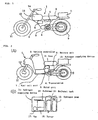
- Fig. 1 is a general structural view of a hybrid-driven vehicle according to an embodiment of this invention.
- the hybrid-driven vehicle 1 of this embodiment is applied to a motor bicycle.
- the hybrid-driven vehicle 1 is provided with a hybrid-driven system 2.
- the hybrid-driven system 2 comprises an electric motor unit 3, a transmission 4, a vehicle controller 5, a battery unit 6 and a fuel cell unit 7.
- a fuel cell unit 7 comprised mainly of a fuel cell and a reformer, is disposed rearwardly of a seat 8 and upwardly of a drive wheel 9.
- a methanol tank 13 In front of the seat 8 and between the seat and a front fork 12 for steering a steering wheel 11, is disposed a methanol tank 13.
- the methanol tank 13 is provided with a filler cap 14.
- the hybrid system comprised of a fuel cell in the fuel cell unit 7 and a battery in the battery unit 6 is adapted to drive an electric motor in the electric motor unit 3 to rotate the drive wheel 9.
- Fig. 2(A) is a view of an example of another type of hybrid-driven motor bicycle
- Fig. 2(B) is a structural view of a hydrogen supplying device for the fuel cell.
- the hybrid-driven vehicle 1 has a vehicle controller 5 and a battery unit 6 under a seat 8; under an vehicle controller 5 is provided an electric motor unit 3; and in front thereof is provided a fuel cell unit 7 comprised mainly of a fuel cell. On a carrier to the rear of the seat 8 is provided a hydrogen supplying device 15 for supplying hydrogen for power generation to the fuel cell unit 7.
- the hydrogen supplying device 15 as shown in Fig. 2(B), is provided with a hydrogen bomb 16 together with a methanol tank 13, and with a fan 17 and a burner 18 for supplying combustion air, and further with a reformer 19 for producing hydrogen through catalyst, with primary fuel being heated and vaporized.
- Fig. 3 is a schematic block diagram of the hybrid-driven vehicle according to this invention.
- the hybrid-driven vehicle 1 is provided with a main switch SW1, a seat 8, a stand 20, a foot rest 21, an acceleration grip 22, a brake 23, an indicator 24, a lamp unit 25 including a light, a winker, etc, a user input device 26, a non-volatile memory 27 and a timer 28, and further with an electric motor unit 3, a transmission 4, a vehicle controller 5, a battery unit 6 and a fuel cell unit 7.
- ON/OFF signals are sent from the main switch SW1 to the vehicle controller 5 to drive the motor-powered vehicle.
- To the seat 8, stand 20, foot rest 21 and brake 23 are fitted sensors S1-S4, respectively, and ON/OFF signals corresponding to seating/non-seating, use/non-use of the stand, feet-resting/non feet-resting and ON/OFF of the brake are sent from the respective sensors S1-S4 to the vehicle controller 5, where the respective operating conditions are detected.
- the accelerator grip 22 constitutes output setting means, and to the accelerator grip 22 is fitted an accelerator opening sensor S5, from which signals of accelerator opening are sent to the vehicle controller 5 through gripping manipulation of the user.
- the electric motor is controlled according to accelerator opening.
- the vehicle controller 5 constitutes control means for controlling the output of the electric motor based on the output setting value from the output setting means constituted by the accelerator grip 22.
- the user is able to input various data from a user input device 26 to the vehicle controller 5 to change, for example, the operating characteristics of the vehicle. Also, data are transferred between the non-volatile memory 27 and timer 28 and the vehicle controller 5, that is, to the non-volatile memory 27 is stored the information on the operating conditions of the vehicle at the time of stoppage, and the vehicle controller 5 reads the information on the stored operating conditions for control when operation is started.
- the indicator 24 is driven by indicator-ON/OFF signals from the vehicle controller 5 and the operating conditions of the motor-powered vehicle are indicated on the indicator 24.
- the lamp unit 25 including a light, winker, etc is comprised of lamps 25b of the light, winker, etc.
- Activation-ON/OFF signals from the vehicle controller 5 drive a DC/DC converter 25a to light the lamps 25b.
- the electric motor unit 3 is provided with a motor driver 30, an electric motor 31 connected to the drive wheel 9, an encoder 32, a regenerative current sensor S11 and regenerative energy control means 33.
- the motor driver 30 controls the electric motor 31 through duty signals from the vehicle controller 5, and the drive wheel 9 is driven by the output of the electric motor 31.
- the encoder 32 detects the position of the magnetic poles and the number of revolution of the electric motor 31. Information on the motor speed from the encoder 32 is stored in a memory in the motor driver 30 to be sent to the vehicle controller 5 as required.
- Output of the electric motor 31 is changed in its speed by the transmission 4 to drive the drive wheel 9, and the transmission 4 is controlled by speed-change command signals from the vehicle controller 5.
- the electric motor 31 is provided with a motor voltage sensor or a motor current sensor S7, and information on the voltage and current of the motor is stored in a memory in the motor driver to be sent to the vehicle controller 5 as required.
- the battery unit 6 is provided with a battery 60, a battery controller 61 and a battery relay 62.
- the fuel cell unit 7 is provided with a fuel cell 70 constituting power generating means, a fuel cell controller 71, a reverse current prevention element 72 and a fuel cell relay 73.
- a first power supply path L1 allowing supply of the output current from the fuel cell 70 to the battery 60
- a second power supply path L2 allowing supply of the output current from the battery 60 to the electric motor 31, and electric power is supplied through an electric power regulating section 80.
- the battery controller 61 is provided with detection means for detecting the charging state of the battery 60, and the detection means is comprised of a battery temperature sensor S12, a battery voltage sensor S13 and a battery current sensor S14, and information from these sensors is stored in a memory in the battery controller 61 to be entered in the vehicle controller 5 as required.
- the battery relay 62 is activated by ON/OFF signals from the vehicle controller 5 to control electric power supply from the second power supply path L2.
- Communication data are sent from the vehicle controller 5 to the fuel cell controller 71, and the fuel cell controller 71 controls the fuel cell 70 on the basis of these data.
- the fuel cell controller 71 is provided with detection means for detecting the state of the fuel cell 70.
- the detection means is comprised of various temperature sensors S21, a fuel cell voltage sensor S22 and a fuel cell current sensor S23, and information from these sensors is stored in a memory in the fuel cell controller 71 to be entered in the vehicle controller 5 as required.
- the fuel cell relay 73 connected to the fuel cell controller through rectifier diode (reverse current prevention element) 72 is activated by ON/OFF signals from the vehicle controller 5 to control electric power supply from the first power supply path L1.
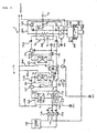
- Fig. 4 is a structural diagram of a portion of a fuel cell according to an embodiment of this invention.
- the fuel cell unit 7 in this embodiment comprises a methanol tank 102, a reformer 103, a shift converter 104, a selective oxidation reactor 105, a fuel cell 70, a moisture collecting heat exchanger 107, a water tank 108 and a fuel cell battery controller 71.
- the fuel cell controller 71 is connected to the devices such as valves, pumps and fans, and sensors.
- the reformer 103, shift converter 104, selective oxidation reactor 105 and fuel cell 70 are provided with temperature sensors Tr, Tb, Ts, Tp, Tc, and the temperature of these components is controlled properly by the fuel cell battery controller 71 (Fig. 3) through temperature detection.
- the reformer 103 is provided with a burner 110, an evaporator 111 and a catalyst layer 112.
- To the burner 110 is supplied methanol from the methanol tank 102 by a burner pump 113 activated through temperature detection by the temperature sensor Tb, and air by a burner fan 114, and the evaporator 111 is heated by combustion action of the mixture.
- the double circle in the figure represents an air inlet.
- To the evaporator 111 is supplied methanol fed from the methanol tank 102 by the methanol pump 115, and water fed from the water tank 108 by the water pump 116, with methanol and water mixed together.
- the burner 110 heats the evaporator 111 to vaporize the fuel mixture of methanol and water, and the vaporized fuel mixture in the evaporator 111 is supplied to the catalyst layer 112.
- the burner 110 To the burner 110 is supplied surplus (or bypassing) hydrogen from the fuel cell 70 through a line 201 for combustion.
- the combustion heat of the burner 110 vaporizes primary fuel (raw material) composed of methanol and water, and heats the catalyst layer 112 to maintain its temperature at a value required for catalytic reaction. Combustion gas, and air not involved in the reaction are discharged to the outside through an exhaust passage 202.
- the catalyst layer 112 is made, for example, of Cu-base catalyst, and resolves the mixture of methanol and water into hydrogen and carbon dioxide at a catalyst reaction temperature of about 300 °C as follows: CH 3 OH + H 2 O ⁇ 3H 2 + CO 2
- carbon monoxide in the resolved gas is turned to CO2 at a reaction temperature of about 200 °C in the following chemical reaction by surplus water vapor: CO + H 2 O ⁇ H 2 + CO 2 and CO concentration is lowered to the order of about 0.1%.
- CO is further changed chemically to CO 2 at a catalyst temperature of about 120 °C using platinum-base catalyst in the oxidation reaction as: 2CO + O 2 ⁇ 2CO 2 and its concentration is reduced further to 1/10 of the previous value or smaller.
- the CO concentration in the cell 70 can be lowered to the order of some tens of ppm.
- the reformer 103 allows raw material to be reformed so as to produce hydrogen as described above, and the hydrogen acquired is supplied to the fuel cell 70 through the shift converter 104 and the selective oxidation reactor 105. Between the reformer 103 and the shift converter 104 are provided a buffer tank 117 for absorbing pulsation and pressure change and switching valves 117a, 117b, and the hydrogen is returned to the burner 110 through activation of these switching valves 117a, 117b.
- the shift converter 104 is cooled by a cooling fan 118 after temperature detection by the temperature sensor Ts. Cooling air is discharged to the outside through an exhaust passage 203.
- a buffer tank 124 and switching valves 124a, 124b are provided between the shift converter 104 and the selective oxidation reactor 105.
- Hydrogen sent from the shift converter 104 is mixed with air fed by a reaction air pump 119 to be supplied to the selective oxidation reactor 105.
- the selective oxidation reactor 105 is cooled by a cooling fan 120 after temperature detection by the temperature sensor Tp.
- the cooling air is discharged to the outside through an exhaust passage 204.
- a buffer tank 121 and switching valves 121a, 1241 are provided between the selective oxidation reactor 105 and the fuel cell 70.
- hydrogen is returned to the burner 110 in the reformer 103 through activation of these switching valves.
- the amount of hydrogen supplied to the fuel cell 70 can be regulated for electromotive force control. Excessive oxygen is supplied in this case, so that the electromotive force is controlled according to the amount of hydrogen.
- Such an electromotive force control is performed as follows: required electromotive force is calculated by the vehicle controller 5 based on the data from sensors S21-S23 and the detected data on the operating conditions from other various sensors, the flow rate of each switching valve is calculated by the vehicle controller 5 or the fuel cell controller 71 based on the calculation results, taking account of the time lag required for the hydrogen quantity in the cell to be changed after activation of the switching valve, on the basis of which ON/OFF control or opening control of each switching valve is performed by the fuel cell controller 71.
- a larger supply quantity of the primary fuel such as methanol may increase the amount of evaporation of hydrogen to thereby increase the electromotive force, in which case time lag is produced by the time hydrogen is increased in quantity enough to participate in power generation.
- time lag is compensated for by the electric power from the battery.
- To the fuel cell 70 is supplied water from the water tank 108 by a cooling and humidifying pump 122, and air is supplied from the moisture collection heat exchanger 107 by a pressurizing air pump 123 through temperature detection of the temperature sensor Tc. Using the water, air and hydrogen, power generation is performed in the fuel cell 70, as described below.
- the fuel cell 70 is configured such that electrodes are each formed with, for example, a platinum-base porous catalyst layer (not shown) provided on both sides of a cell film (not shown) with a cooling and humidifying water passage 205 formed therein.
- a platinum-base porous catalyst layer (not shown) provided on both sides of a cell film (not shown) with a cooling and humidifying water passage 205 formed therein.
- oxygen (air) supplied to one electrode is supplied hydrogen from the selective oxidation reactor 105 through a hydrogen passage 206, and to the other electrode, oxygen (air) through an oxygen passage 207.
- Hydrogen ions move from the hydrogen passage 205 of the hydrogen side electrode to the oxygen side electrode through the cell film and are combined with oxygen to form water.
- the migration of electrons (-) associated with the migration of the hydrogen ions (+) allows the electromotive force to be generated between the electrodes.
- This electromotive force generation is a heat development reaction, and for the purpose of cooling and smooth migration of hydrogen ions to the oxygen side electrode, water is supplied from the water tank 108 to the water passage 205 in the cell film between both electrodes by the pump 122.
- the water tank 108 is provided with a radiation fins 208 for cooling water.
- Numeral 209 designates an overflow pipe.
- Air is introduced to the heat exchanger 107.
- the air after exchanging heat with water at an elevated temperature, is changed to a hot air, and supplied to the oxygen passage 207 by the air pump 123.
- an air inlet shown in the figure by a double circle
- Oxygen in the air passing through the oxygen passage 207 and combined with hydrogen ions is turned into water and collected in the water tank 108.
- the surplus air (oxygen and nitrogen) is discharged to the outside through an exhaust passage 210.
- the reformer 103 in which the evaporator 111 is heated by the burner 110 and raw material vaporized by the evaporator 111 is supplied to the catalyst layer 112, the raw material is reformed to produce hydrogen, and the hydrogen acquired is supplied to the fuel cell 70 through the shift converter 104 and the selective oxidation reactor 105 for power generation.
- hydrogen acquired from the selective oxygen reactor 105 may be stored, as shown in Fig. 2(B), temporarily in the hydrogen bomb 16.
- the output of the fuel cell 70 is connected to the power regulating section 80 through the reverse current prevention element 72 and the fuel cell battery relay 73, and the power regulating section 80 is connected to the battery 60 and the electric motor 31.
- Fig. 5 is a block diagram of the power source control system of the hybrid-driven vehicle according to this invention.
- the vehicle controller 5 is connected to the electric motor unit 3, battery unit 6 and fuel cell unit 7 through bilateral communication lines 220, 221, 222, respectively.
- the fuel cell unit 7 is connected to the electric motor unit 3 through (+) side current line 223a and (-) side current line 223b.
- a switch 225 On the (+) side current line 223a is provided a switch 225. This switch 225 is turned ON and OFF by the vehicle controller 5.
- the battery unit 6 is connected to the electric motor unit 3 through the (+) side current line 223a and the (-) side current line 223b which are coupled to the (+) side current line 224a and (-) side current line 224b, respectively.
- a switch 226 On the (+) side current line 224a is provided a switch 226. This switch 226 is turned ON and OFF by the vehicle controller 5.
- the electric motor unit 3 is a unit in which a controller (motor driver 30), an encoder and sensors, as well as an electric motor 31 (Fig. 3), are integrated together as a module.
- a controller motor driver 30
- an encoder and sensors as well as an electric motor 31 (Fig. 3)
- an electric motor unit 3 can be mounted detachably on a vehicle as a unitary component. Therefore, the bilateral communication line 220 and the current lines 223a, 223b, 224a, 224b are each connected to the motor driver 30 as a controller of the electric motor unit 3 through the respective couplers (not shown).
- the motor driver 30 has a memory, and detected data such as the operating conditions of the electric motor unit 3 (for example, number of revolution), throttle opening, running speed, request load, temperature and shift position are sent to the vehicle controller 5 to update the memory in the vehicle controller 5 for storage.
- detected data such as the operating conditions of the electric motor unit 3 (for example, number of revolution), throttle opening, running speed, request load, temperature and shift position are sent to the vehicle controller 5 to update the memory in the vehicle controller 5 for storage.
- the battery unit 6 is a unit in which a battery controller 61, sensors S12-S14 and a relay 52, as well as a battery 60 as shown in Fig. 3, are integrated together as a module. Such a battery unit 6 can be mounted detachably on a vehicle as a unitary component. Therefore, the bilateral communication line 221 and the current lines 224a, 224b are connected to the battery controller 61 of the battery unit 6 through couplers (not shown).
- the battery controller 61 has a memory, to which are stored the data on the battery unit conditions such as temperature, voltage and current, and the residual capacity of the battery 60 while updated constantly.
- the data can be transferred through bilateral communication between the battery controller and the vehicle controller to supply required power during running, and when the battery 60 is replaced, the residual capacity can be immediately recognized by the vehicle controller for processing of expected travel distance, etc.
- the fuel cell unit 7 is a unit in which a fuel cell controller 71, sensors S21-S23 (Fig. 3) and a relay 52, as well as the fuel cell 70, reformer, etc, are integrated together as a module.
- a fuel cell unit 7 can be mounted detachably on a vehicle as a unitary component. Therefore, the bilateral communication line 222 and the current lines 223a, 223b are connected to the fuel cell controller 71 of the fuel cell unit 7 through couplers (not shown).
- the fuel cell controller 71 has a memory, to which are stored the data on the fuel cell unit conditions such as temperature, voltage and current, and the capacity (specifically, the residual fuel in the methanol tank) of the fuel cell while updated constantly.
- the data can be transferred through bilateral communication between the fuel cell controller and the vehicle controller to supply required power during running, and processing of expected travel distance, etc, can be performed.
- a fuel cell and a battery are used as two power supply sources constituting the hybrid-driven vehicle, two fuel cells or two batteries (second batteries) may be used, or an engine type generator or a capacitor may be used.
- this invention can be applied to watercrafts or other devices in addition to vehicles.
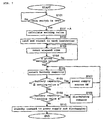
- Fig. 6 is an illustration of data communication in the control system of the hybrid-driven vehicle according to this invention.
- the vehicle controller 5 transmits, to the electric motor unit 3 (motor driver (controller of the electric motor) 30, encoder 32 and other sensor group), battery controller 61 and fuel cell controller 71, request signals of various data stored in the memories of the controllers. Upon this data request, required data are sent back to the vehicle controller 5 from the sensor group of the electric motor unit 3, and the controllers 30, 61. 71.
- the contents of the data include state information such as temperature, voltage, current, error information and capacity, and control information such as output request.
- the vehicle controller 5 calculates, on the basis of the data from the sensor group and the controllers 30, 61, 71, the optimum amount of drive to the units, and the data on the amount of drive are sent, as operation command data, to the motor driver 30 and controllers 30, 61, 71 for the control of the electric motor unit 3, battery unit 6 and fuel cell unit 7.
- the vehicle controller 5 determines accordingly whether the abnormality happens in the battery unit 6 or the fuel cell unit 7, and cuts off the switch 225 or 226 (Fig. 5) of the power source where the abnormality is detected, to stop power supply from the abnormal power source to the motor.
- the switches 225, 226 correspond to the fuel cell relay 73 and the battery relay 62 of Fig. 3, respectively.
- the battery unit 6 is determined to be abnormal when the detection value of any of the battery temperature sensor S12, battery voltage sensor S13 and battery current sensor S14 is excessively large or small beyond the range of normal detection values, and this detection value is stored as detection data on abnormality in the memory of the battery controller 61.
- the fuel cell unit 7 is determined to be abnormal when the detection value of any of the temperature sensor S21, fuel cell voltage sensor S22 and fuel cell current sensor S23 is excessively large or small beyond the range of normal detection values, and this detection value is stored as detection data on abnormality in the memory of the fuel cell controller 71.
- the vehicle controller 5 constantly sends to the controllers 61, 71 data requests including the detection data on abnormality, and if an abnormal state exists, the data is sent back to the vehicle controller 5.
- the vehicle controller receives the detection data on abnormality, connection between the power source and the motor is cut off as described above.
- the battery controller 61 or the fuel cell controller 71 that has detected the abnormality may send a request signal for stoppage of discharging of the abnormal battery or the fuel cell, to stop the use of the battery or the fuel cell.
- the vehicle controller 5 that has received the request signal for stoppage of discharging determines whether the battery or the fuel cell needs to stop discharging, and cuts off the switch 225 or 226 of the abnormal power source to stop the use of the power source.
- Such a bilateral communication of the detection data on abnormality allows a prompt action against abnormality at the time of occurrence of abnormality in the power source. In this case, even if the failure of the sensor itself is detected as abnormality of the power source, it can be handled as an abnormal state.
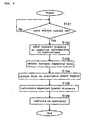
- Fig. 7 is a flowchart of control of the power supply system during non-running of the hybrid-driven vehicle according to this invention.
- the current and voltage may be detected in an approximately constant current state generated by quick change over of the battery switch (FET, etc), and the residual battery capacity and the impedance may be calculated from the current and voltage characteristics in this constant current state.
- FET battery switch
- the motor, fuel cell and battery are arranged as module units containing controllers, respectively, efficiency of assembling work and maintainability of modules are improved and control systems corresponding to the modules are integrated for the respective modules, thereby providing improved reliability of the control, easy parts replacement including that of the control system parts and improved applicability of modules with effective parts control.
- the device (vehicle) controller which controls the whole device is adapted to perform bilateral data communication with the module controllers such as the motor, battery and fuel cell, then data is stored in each module controller and the device controller can receive requisite data on request to the module controller, so that memory structure is simplified on the device controller side, and effective control can be performed on the same communication line for each module.
- module controllers such as the motor, battery and fuel cell
- the capacity of the fuel cell or the battery is detected to be optimized sufficiently enough for normal operation, so that the device can be held on standby in an optimum condition that operation can be started stably and reliably at the time of next running, for continuation of normal operation.
- the available amount of power supply of each of the first and the second power source constituting the hybrid device for example, residual capacity or residual fuel
- the expected travel distance of the mobile body is calculated on the basis of the detected data
- stable operation to the destination is verified and a prompt action can be taken when the expected travel distance or the residual quantity is insufficient.
- the use of the abnormal power source is stopped promptly and operation is continued using the other power source while an appropriate action is taken against the abnormality, thereby minimizing damage.
Landscapes
- Engineering & Computer Science (AREA)
- Life Sciences & Earth Sciences (AREA)
- Sustainable Energy (AREA)
- Sustainable Development (AREA)
- Chemical & Material Sciences (AREA)
- Electrochemistry (AREA)
- Chemical Kinetics & Catalysis (AREA)
- General Chemical & Material Sciences (AREA)
- Manufacturing & Machinery (AREA)
- Transportation (AREA)
- Mechanical Engineering (AREA)
- Power Engineering (AREA)
- Combustion & Propulsion (AREA)
- Electric Propulsion And Braking For Vehicles (AREA)
- Fuel Cell (AREA)
Applications Claiming Priority (7)
| Application Number | Priority Date | Filing Date | Title |
|---|---|---|---|
| JP24079199 | 1999-08-27 | ||
| JP24079199A JP2001069612A (ja) | 1999-08-27 | 1999-08-27 | ハイブリッド駆動装置 |
| JP24255799A JP2001069614A (ja) | 1999-08-30 | 1999-08-30 | ハイブリッド駆動式移動体 |
| JP24255799 | 1999-08-30 | ||
| JP24649399A JP2001069615A (ja) | 1999-08-31 | 1999-08-31 | ハイブリッド駆動装置 |
| JP24649399 | 1999-08-31 | ||
| PCT/JP2000/005660 WO2001015929A1 (fr) | 1999-08-27 | 2000-08-24 | Système d'entraînement hybride |
Publications (2)
| Publication Number | Publication Date |
|---|---|
| EP1132251A1 true EP1132251A1 (fr) | 2001-09-12 |
| EP1132251A4 EP1132251A4 (fr) | 2011-08-31 |
Family
ID=27332863
Family Applications (1)
| Application Number | Title | Priority Date | Filing Date |
|---|---|---|---|
| EP00954945A Withdrawn EP1132251A4 (fr) | 1999-08-27 | 2000-08-24 | Syst me d'entra nement hybride |
Country Status (4)
| Country | Link |
|---|---|
| US (1) | US6793027B1 (fr) |
| EP (1) | EP1132251A4 (fr) |
| CA (1) | CA2347666C (fr) |
| WO (1) | WO2001015929A1 (fr) |
Cited By (24)
| Publication number | Priority date | Publication date | Assignee | Title |
|---|---|---|---|---|
| WO2001048847A2 (fr) * | 1999-12-23 | 2001-07-05 | Siemens Aktiengesellschaft | Dispositif de piles a combustible et procede d'utilisation de ce dispositif |
| FR2823473A1 (fr) * | 2001-04-17 | 2002-10-18 | Renault | Procede et systeme de commande d'un dispositif de pile a combustible pour vehicule automobile |
| FR2831354A1 (fr) * | 2001-10-19 | 2003-04-25 | Peugeot Motocycles Sa | Systeme de caracterisation du fonctionnement d'organes fonctionnels d'un vehicule a deux roues du type scooter |
| EP1389552A1 (fr) * | 2002-08-16 | 2004-02-18 | Yamaha Hatsudoki Kabushiki Kaisha | Véhicule à commande électrique |
| EP1398263A1 (fr) * | 2002-09-16 | 2004-03-17 | Asia Pacific Fuel Cell Technologies, Ltd. | Scooter électrique avec système de piles à combustible |
| US6722460B2 (en) | 2002-09-16 | 2004-04-20 | Asia Pacific Fuel Cell Technologies, Ltd. | Electric scooter with fuel cell engine assembly |
| EP1419926A2 (fr) * | 2002-11-18 | 2004-05-19 | HONDA MOTOR CO., Ltd. | Véhicule équipé d'une pile à combustible |
| WO2006082377A1 (fr) * | 2005-02-01 | 2006-08-10 | Intelligent Energy Limited | Pile a combustible amovible pour vehicules |
| EP1767448A1 (fr) * | 2005-09-26 | 2007-03-28 | Yamaha Hatsudoki Kabushiki Kaisha | Véhicule électrique |
| EP1772362A1 (fr) * | 2005-10-04 | 2007-04-11 | Yamaha Hatsudoki Kabushiki Kaisha | Motocyclette avec un réservoir d'hydrogène |
| FR2901071A1 (fr) * | 2006-05-09 | 2007-11-16 | Renault Sas | Systeme et procede de production d'energie electrique pour vehicule automobile a moteur de traction electrique |
| US7550942B2 (en) | 2005-12-21 | 2009-06-23 | Yamaha Hatsudoki Kabushiki Kaisha | Hybrid power supply system and controller for warm-up mode |
| EP2131428A1 (fr) * | 2007-03-23 | 2009-12-09 | Honda Motor Co., Ltd. | Dispositif de pile à combustible |
| EP2385572A1 (fr) * | 2009-12-10 | 2011-11-09 | Panasonic Corporation | Système de pile à combustible et dispositif électronique |
| EP2530775A1 (fr) * | 2011-05-31 | 2012-12-05 | Aisin Seiki Kabushiki Kaisha | Système de pile à combustible |
| EP2361827A3 (fr) * | 2010-02-19 | 2013-03-27 | Yamaha Hatsudoki Kabushiki Kaisha | Motocyclette électrique |
| WO2013045043A1 (fr) * | 2011-10-01 | 2013-04-04 | Daimler Ag | Dispositif destiné au stockage d'un combustible gazeux |
| EP2796312A4 (fr) * | 2011-12-22 | 2016-03-16 | Sony Corp | Dispositif de stockage électrique, instrument électronique, système d'alimentation et véhicule électrique |
| CN107000568A (zh) * | 2014-11-25 | 2017-08-01 | 雅马哈发动机株式会社 | 车辆和用于驱动车辆的发动机发电机单元 |
| CN107487331A (zh) * | 2016-09-19 | 2017-12-19 | 宝沃汽车(中国)有限公司 | 一种车辆控制方法、车载终端以及车辆控制系统 |
| CN109546184A (zh) * | 2017-09-21 | 2019-03-29 | 丰田自动车株式会社 | 燃料电池系统以及燃料电池系统的控制方法 |
| DE102018205948A1 (de) | 2018-04-19 | 2019-10-24 | Volkswagen Aktiengesellschaft | Gehäuse mit Batteriezellen zur Bildung zumindest eines Teils einer Traktionsbatterie für ein elektrisch antreibbares Kraftfahrzeug |
| CN111152691A (zh) * | 2020-01-10 | 2020-05-15 | 风氢扬科技(杭州)有限公司 | 一种功率控制方法、装置、系统、整车控制器及存储介质 |
| EP3782210B1 (fr) * | 2018-07-17 | 2023-01-11 | Audi AG | Système d'énergie électrique comprenant des piles à combustible |
Families Citing this family (71)
| Publication number | Priority date | Publication date | Assignee | Title |
|---|---|---|---|---|
| US6602271B2 (en) | 2000-05-24 | 2003-08-05 | Medtronic Ave, Inc. | Collapsible blood filter with optimal braid geometry |
| US20030064262A1 (en) * | 2001-05-31 | 2003-04-03 | Plug Power Inc. | Method and apparatus for controlling a combined heat and power fuel cell system |
| EP1424494A1 (fr) * | 2002-11-27 | 2004-06-02 | Continental ISAD Electronic Systems GmbH & Co. oHG | Dispositif de propulsion hybride et méthode pour l'application commune d'un couple de propulsion |
| JP2004326386A (ja) * | 2003-04-24 | 2004-11-18 | Mitsubishi Electric Corp | 評価支援装置及び評価支援方法及び評価支援プログラム |
| JP2005032039A (ja) * | 2003-07-07 | 2005-02-03 | Sony Corp | 電子機器及び電子機器の電源管理制御方法、並びに電源装置 |
| DE10330814A1 (de) * | 2003-07-08 | 2005-02-03 | Still Gmbh | Industrieschlepper mit elektrischem Fahrantrieb |
| DE10341838A1 (de) * | 2003-09-09 | 2005-04-28 | Siemens Ag | Verfahren zur Steuerung von Energieströmen |
| US7655331B2 (en) * | 2003-12-01 | 2010-02-02 | Societe Bic | Fuel cell supply including information storage device and control system |
| JP4217800B2 (ja) * | 2004-07-14 | 2009-02-04 | ヤマハマリン株式会社 | 船舶の電力制御装置及び船舶 |
| EP1790320A1 (fr) * | 2004-08-18 | 2007-05-30 | Kurimoto, Ltd. | Fauteuil roulant motorisé |
| US7478698B2 (en) * | 2004-08-19 | 2009-01-20 | Honda Motor Co., Ltd. | Arrangement of intake and exhaust system components in a fuel cell powered vehicle |
| JP4296144B2 (ja) * | 2004-09-29 | 2009-07-15 | 本田技研工業株式会社 | 燃料電池二輪車 |
| US20060289213A1 (en) * | 2005-06-16 | 2006-12-28 | Cervantes Adan R | Hydrogen fuel cell vehicle with wireless diagnostics |
| JP4281725B2 (ja) * | 2005-09-01 | 2009-06-17 | トヨタ自動車株式会社 | ハイブリッド自動車 |
| US20070052386A1 (en) * | 2005-09-08 | 2007-03-08 | Yi-Hsiung Lin | Automatic chargeable electromotive vehicle |
| CA2523240C (fr) * | 2005-10-11 | 2009-12-08 | Delaware Systems Inc. | Module batterie universel et module de commande connexe |
| US20070087239A1 (en) * | 2005-10-18 | 2007-04-19 | General Hydrogen Corporation | Fuel cell fluid management system |
| US20070087232A1 (en) * | 2005-10-18 | 2007-04-19 | Robin Curtis M | Capacitor hybrid fuel cell power generator |
| US20070087241A1 (en) * | 2005-10-18 | 2007-04-19 | General Hydrogen Corporation | Fuel cell power pack |
| JP4238875B2 (ja) * | 2006-02-10 | 2009-03-18 | トヨタ自動車株式会社 | ハイブリッド車用電池寿命評価装置 |
| KR100837394B1 (ko) * | 2006-08-17 | 2008-06-12 | 삼성에스디아이 주식회사 | Co 제거유닛의 워밍업 구조가 개선된 연료개질기 및 그운영방법 |
| JP2008084809A (ja) * | 2006-08-29 | 2008-04-10 | Yamaha Motor Co Ltd | 水素供給用配管の接続構造 |
| JP4925108B2 (ja) * | 2007-01-10 | 2012-04-25 | ヤマハモーターパワープロダクツ株式会社 | 電動ゴルフカート |
| WO2008110470A2 (fr) * | 2007-03-13 | 2008-09-18 | Zf Friedrichshafen Ag | Procédé de détermination de la vitesse de rotation de sortie d'une transmission |
| JP4935563B2 (ja) * | 2007-07-30 | 2012-05-23 | 日産自動車株式会社 | 燃料電池システムおよび燃料電池システムの制御方法 |
| US8193761B1 (en) | 2007-11-08 | 2012-06-05 | Honeywell International, Inc. | Hybrid power source |
| EP2218678A4 (fr) * | 2007-11-13 | 2014-03-19 | Panasonic Corp | Appareil pour le traitement de combustible et procédé pour sa mise en marche |
| JP4968159B2 (ja) * | 2008-04-15 | 2012-07-04 | トヨタ自動車株式会社 | ハイブリッド車両の制御装置 |
| DE102008023805B4 (de) * | 2008-05-15 | 2024-03-21 | Bayerische Motoren Werke Aktiengesellschaft | Verfahren zur Schaltpunktsteuerung bei Automatikgetrieben |
| DE102008054008A1 (de) * | 2008-10-30 | 2010-05-06 | Bayerische Motoren Werke Aktiengesellschaft | Informationsvorrichtung |
| US20100280709A1 (en) * | 2009-04-30 | 2010-11-04 | Searete Llc, A Limited Liability Corporation Of The State Of Delaware | Awarding standings to a vehicle based upon one or more fuel utilization characteristics |
| US20100280688A1 (en) * | 2009-04-30 | 2010-11-04 | Searete Llc, A Limited Liability Corporation Of The State Of Delaware | Awarding standings to a vehicle based upon one or more fuel utilization characteristics |
| US8855907B2 (en) * | 2009-04-30 | 2014-10-07 | Searete Llc | Awarding privileges to a vehicle based upon one or more fuel utilization characteristics |
| US20100280693A1 (en) * | 2009-04-30 | 2010-11-04 | Searete Llc, A Limited Liability Corporation Of The State Of Delaware | Awarding standings to a vehicle based upon one or more fuel utilization characteristics |
| US20110106591A1 (en) * | 2009-04-30 | 2011-05-05 | Searete Llc, A Limited Liability Corporation Of The State Of Delaware | Awarding standings to a vehicle based upon one or more fuel utilization characteristics |
| US20100280705A1 (en) * | 2009-04-30 | 2010-11-04 | Searete Llc, A Limited Liability Corporation Of The State Of Delaware | Awarding standings to a vehicle based upon one or more fuel utilization characteristics |
| US20100280704A1 (en) * | 2009-04-30 | 2010-11-04 | Searete Llc, A Limited Liability Corporation Of The State Of Delaware | Awarding standings to a vehicle based upon one or more fuel utilization characteristics |
| US20100280888A1 (en) * | 2009-04-30 | 2010-11-04 | Searete LLC, a limited libaility corporation of the State of Delaware | Awarding privileges to a vehicle based upon one or more fuel utilization characteristics |
| US20100280691A1 (en) * | 2009-04-30 | 2010-11-04 | Searete Llc, A Limited Liability Corporation Of The State Of Delaware | Awarding standings to a vehicle based upon one or more fuel utilization characteristics |
| US20100280885A1 (en) * | 2009-04-30 | 2010-11-04 | Searete Llc, A Limited Liability Corporation Of The State Of Delaware | Awarding privileges to a vehicle based upon one or more fuel utilization characteristics |
| US20100280887A1 (en) * | 2009-04-30 | 2010-11-04 | Searete Llc, A Limited Liability Corporation Of The State Of Delaware | Awarding privileges to a vehicle based upon one or more fuel utilization characteristics |
| US20100280706A1 (en) * | 2009-04-30 | 2010-11-04 | Searete Llc, A Limited Liability Corporation Of State Of Delaware | Awarding standings to a vehicle based upon one or more fuel utilization characteristics |
| US20100280707A1 (en) * | 2009-04-30 | 2010-11-04 | Searete Llc, A Limited Liability Corporation Of State Of Delaware | Awarding standings to a vehicle based upon one or more fuel utilization characteristics |
| US20100280690A1 (en) * | 2009-04-30 | 2010-11-04 | Searete Llc, A Limited Liability Corporation Of The State Of Delaware | Awarding standings to a vehicle based upon one or more fuel utilization characteristics |
| US20100280708A1 (en) * | 2009-04-30 | 2010-11-04 | Searete Llc, A Limited Liability Corporation Of The State Of Delaware | Awarding standings to a vehicle based upon one or more fuel utilization characteristics |
| US20100280689A1 (en) * | 2009-04-30 | 2010-11-04 | Searete Llc, A Limited Liability Corporation Of The State Of Delaware | Awarding standings to a vehicle based upon one or more fuel utilization characteristics |
| US20100280686A1 (en) * | 2009-04-30 | 2010-11-04 | Searete Llc, A Limited Liability Corporation Of The State Of Delaware | Awarding privileges to a vehicle based upon one or more fuel utilization characteristics |
| US20110106354A1 (en) * | 2009-04-30 | 2011-05-05 | Searete Llc, A Limited Liability Corporation Of The State Of Delaware | Awarding standings to a vehicle based upon one or more fuel utilization characteristics |
| US20100280692A1 (en) * | 2009-04-30 | 2010-11-04 | Searete Llc, A Limited Liability Corporation Of The State Of Delaware | Awarding standings to a vehicle based upon one or more fuel utilization characteristics |
| US20100280886A1 (en) * | 2009-04-30 | 2010-11-04 | Searete Llc, A Limited Liability Corporation Of The State Of Delware | Awarding privileges to a vehicle based upon one or more fuel utilization characteristics |
| JP5417992B2 (ja) * | 2009-05-27 | 2014-02-19 | スズキ株式会社 | 燃料電池車両 |
| US8126603B2 (en) * | 2009-05-29 | 2012-02-28 | GM Global Technology Operations LLC | Reduction of shift occurrences associated with hybrid vehicles |
| FR2947222A1 (fr) * | 2009-06-30 | 2010-12-31 | Daniel Giudice | Procede de fonctionnement d'un vehicule hybride et dispositif de controle associe. |
| US10093303B2 (en) * | 2009-08-18 | 2018-10-09 | Ford Global Technologies, Llc | Method and system for determining a plug-in hybrid electric vehicle expected drive range |
| US20110087389A1 (en) * | 2009-10-09 | 2011-04-14 | Gm Global Technology Operations, Inc. | Standby mode for optimization of efficiency and durability of a fuel cell vehicle application |
| JP5461241B2 (ja) * | 2010-03-03 | 2014-04-02 | 本田技研工業株式会社 | 変速制御装置 |
| US8180512B2 (en) * | 2010-08-10 | 2012-05-15 | Tesla Motors, Inc. | Efficient dual source battery pack system for an electric vehicle |
| US8423215B2 (en) | 2010-08-10 | 2013-04-16 | Tesla Motors, Inc. | Charge rate modulation of metal-air cells as a function of ambient oxygen concentration |
| DE112011103180A5 (de) * | 2010-09-24 | 2013-07-25 | Magna E-Car Systems Gmbh & Co Og | Elektrokraftfahrzeug und Redox-Flow-Modul sowie Kartusche hierzu |
| US20150017485A1 (en) * | 2011-12-28 | 2015-01-15 | Toyota Jidosha Kabushiki Kaisha | Fuel cell system |
| US10339621B2 (en) * | 2014-03-19 | 2019-07-02 | Nissan Motor Co., Ltd. | Operator management device, operator management system, and operator management method |
| KR101558750B1 (ko) * | 2014-03-24 | 2015-10-08 | 현대자동차주식회사 | 연료전지의 출력 회복 시스템 및 방법 |
| WO2017054079A1 (fr) * | 2015-09-29 | 2017-04-06 | Verail Technologies, Inc. | Locomotives |
| JP2017081326A (ja) * | 2015-10-27 | 2017-05-18 | スズキ株式会社 | 燃料電池二輪車の配管継手配置構造 |
| JP6315293B2 (ja) * | 2016-02-22 | 2018-04-25 | トヨタ自動車株式会社 | 電力供給方法及び電力供給システム |
| JP6788836B2 (ja) | 2016-12-05 | 2020-11-25 | スズキ株式会社 | 燃料電池船 |
| JP6819252B2 (ja) | 2016-12-05 | 2021-01-27 | スズキ株式会社 | 燃料電池船 |
| DE102017001567B4 (de) * | 2017-02-20 | 2022-06-09 | Diehl Aerospace Gmbh | Verdampfer und Brennstoffzellenanordnung |
| KR102370145B1 (ko) * | 2017-08-11 | 2022-03-04 | 현대자동차주식회사 | 배터리 관리 장치, 그를 가지는 차량 및 그 제어 방법 |
| KR20230022533A (ko) * | 2021-08-09 | 2023-02-16 | 현대자동차주식회사 | 후방 차체의 플로워 구조 |
| GB2617192A (en) | 2022-04-01 | 2023-10-04 | Ecomar Propulsion Ltd | Control system |
Citations (3)
| Publication number | Priority date | Publication date | Assignee | Title |
|---|---|---|---|---|
| US5631532A (en) * | 1994-02-24 | 1997-05-20 | Kabushikikaisha Equos Research | Fuel cell/battery hybrid power system for vehicle |
| US5898282A (en) * | 1996-08-02 | 1999-04-27 | B.C. Research Inc. | Control system for a hybrid vehicle |
| US5929594A (en) * | 1996-08-29 | 1999-07-27 | Toyota Jidosha Kabushiki Kaisha | Fuel-cells system, electric vehicle with fuel-cells system, and method of controlling supply of electric power |
Family Cites Families (17)
| Publication number | Priority date | Publication date | Assignee | Title |
|---|---|---|---|---|
| US4961151A (en) * | 1983-09-29 | 1990-10-02 | Engelhard Corporation | Fuel cell/battery control system |
| US5397991A (en) * | 1988-07-13 | 1995-03-14 | Electronic Development Inc. | Multi-battery charging system for reduced fuel consumption and emissions in automotive vehicles |
| JPH02168802A (ja) * | 1988-12-22 | 1990-06-28 | Toyota Autom Loom Works Ltd | 電気車 |
| JPH03109126A (ja) | 1989-09-21 | 1991-05-09 | Yamaha Motor Co Ltd | 燃料電池電気自動車 |
| JPH03284104A (ja) | 1990-02-22 | 1991-12-13 | Fuji Electric Co Ltd | 移動電源車 |
| JP3284104B2 (ja) | 1990-10-11 | 2002-05-20 | コベルコ建機株式会社 | ホイールクレーン |
| US5396970A (en) * | 1992-10-09 | 1995-03-14 | Tokyo R&D Co., Ltd. | Electromotive scooter |
| JPH06253409A (ja) * | 1993-02-24 | 1994-09-09 | Aqueous Res:Kk | ハイブリッド電源装置 |
| JPH08237810A (ja) * | 1995-02-27 | 1996-09-13 | Aqueous Res:Kk | ハイブリッド車両 |
| JP3487952B2 (ja) * | 1995-04-14 | 2004-01-19 | 株式会社日立製作所 | 電気自動車の駆動装置及び駆動制御方法 |
| FR2743342B1 (fr) * | 1996-01-05 | 1998-02-13 | Smh Management Services Ag | Procede et dispositif pour regler la repartition de la puissance electrique dans un vehicule automobile, notamment la propulsion hybride |
| JPH10117406A (ja) * | 1996-06-14 | 1998-05-06 | Fuji Photo Film Co Ltd | 電気自動車及びその駆動電源装置 |
| US5820172A (en) * | 1997-02-27 | 1998-10-13 | Ford Global Technologies, Inc. | Method for controlling energy flow in a hybrid electric vehicle |
| US5941328A (en) * | 1997-11-21 | 1999-08-24 | Lockheed Martin Corporation | Electric vehicle with variable efficiency regenerative braking depending upon battery charge state |
| US5929595A (en) * | 1997-11-21 | 1999-07-27 | Lockheed Martin Corporation | Hybrid electric vehicle with traction motor drive allocated between battery and auxiliary source depending upon battery charge state |
| US6091228A (en) * | 1998-04-29 | 2000-07-18 | Lockheed Martin Corp. | Control system for, in the presence of a varying system load, establishing generator current to maintain a particular battery charge state |
| JP2000173675A (ja) | 1998-12-04 | 2000-06-23 | Yazaki Corp | 電気自動車用電池管理装置 |
-
2000
- 2000-08-24 WO PCT/JP2000/005660 patent/WO2001015929A1/fr active Application Filing
- 2000-08-24 EP EP00954945A patent/EP1132251A4/fr not_active Withdrawn
- 2000-08-24 CA CA002347666A patent/CA2347666C/fr not_active Expired - Fee Related
- 2000-08-24 US US09/830,820 patent/US6793027B1/en not_active Expired - Lifetime
Patent Citations (3)
| Publication number | Priority date | Publication date | Assignee | Title |
|---|---|---|---|---|
| US5631532A (en) * | 1994-02-24 | 1997-05-20 | Kabushikikaisha Equos Research | Fuel cell/battery hybrid power system for vehicle |
| US5898282A (en) * | 1996-08-02 | 1999-04-27 | B.C. Research Inc. | Control system for a hybrid vehicle |
| US5929594A (en) * | 1996-08-29 | 1999-07-27 | Toyota Jidosha Kabushiki Kaisha | Fuel-cells system, electric vehicle with fuel-cells system, and method of controlling supply of electric power |
Non-Patent Citations (1)
| Title |
|---|
| See also references of WO0115929A1 * |
Cited By (41)
| Publication number | Priority date | Publication date | Assignee | Title |
|---|---|---|---|---|
| WO2001048847A3 (fr) * | 1999-12-23 | 2003-02-20 | Siemens Ag | Dispositif de piles a combustible et procede d'utilisation de ce dispositif |
| WO2001048847A2 (fr) * | 1999-12-23 | 2001-07-05 | Siemens Aktiengesellschaft | Dispositif de piles a combustible et procede d'utilisation de ce dispositif |
| FR2823473A1 (fr) * | 2001-04-17 | 2002-10-18 | Renault | Procede et systeme de commande d'un dispositif de pile a combustible pour vehicule automobile |
| WO2002083449A1 (fr) * | 2001-04-17 | 2002-10-24 | Renault S.A.S. | Procede et systeme de commande d'un dispositif de pile a combustible pour vehicule automobile |
| FR2831354A1 (fr) * | 2001-10-19 | 2003-04-25 | Peugeot Motocycles Sa | Systeme de caracterisation du fonctionnement d'organes fonctionnels d'un vehicule a deux roues du type scooter |
| EP1389552A1 (fr) * | 2002-08-16 | 2004-02-18 | Yamaha Hatsudoki Kabushiki Kaisha | Véhicule à commande électrique |
| EP1398263A1 (fr) * | 2002-09-16 | 2004-03-17 | Asia Pacific Fuel Cell Technologies, Ltd. | Scooter électrique avec système de piles à combustible |
| US6722460B2 (en) | 2002-09-16 | 2004-04-20 | Asia Pacific Fuel Cell Technologies, Ltd. | Electric scooter with fuel cell engine assembly |
| US7270899B2 (en) | 2002-11-18 | 2007-09-18 | Honda Motor Co., Ltd. | On-board fuel cell powered electric vehicle |
| EP1419926A2 (fr) * | 2002-11-18 | 2004-05-19 | HONDA MOTOR CO., Ltd. | Véhicule équipé d'une pile à combustible |
| EP1419926A3 (fr) * | 2002-11-18 | 2004-06-23 | HONDA MOTOR CO., Ltd. | Véhicule équipé d'une pile à combustible |
| US8011462B2 (en) | 2005-02-01 | 2011-09-06 | Damian Davies | Detachable fuel cell power unit for vehicle applications |
| KR101330764B1 (ko) * | 2005-02-01 | 2013-11-18 | 인텔리전트 에너지 리미티드 | 차량에서의 적용을 위한 분리 가능 연료 전지 전력 유니트 |
| WO2006082377A1 (fr) * | 2005-02-01 | 2006-08-10 | Intelligent Energy Limited | Pile a combustible amovible pour vehicules |
| EP1767448A1 (fr) * | 2005-09-26 | 2007-03-28 | Yamaha Hatsudoki Kabushiki Kaisha | Véhicule électrique |
| EP1772362A1 (fr) * | 2005-10-04 | 2007-04-11 | Yamaha Hatsudoki Kabushiki Kaisha | Motocyclette avec un réservoir d'hydrogène |
| US7550942B2 (en) | 2005-12-21 | 2009-06-23 | Yamaha Hatsudoki Kabushiki Kaisha | Hybrid power supply system and controller for warm-up mode |
| FR2901071A1 (fr) * | 2006-05-09 | 2007-11-16 | Renault Sas | Systeme et procede de production d'energie electrique pour vehicule automobile a moteur de traction electrique |
| EP2131428A1 (fr) * | 2007-03-23 | 2009-12-09 | Honda Motor Co., Ltd. | Dispositif de pile à combustible |
| EP2131428A4 (fr) * | 2007-03-23 | 2010-05-26 | Honda Motor Co Ltd | Dispositif de pile à combustible |
| EP2385572A1 (fr) * | 2009-12-10 | 2011-11-09 | Panasonic Corporation | Système de pile à combustible et dispositif électronique |
| EP2385572A4 (fr) * | 2009-12-10 | 2013-04-03 | Panasonic Corp | Système de pile à combustible et dispositif électronique |
| EP2361827A3 (fr) * | 2010-02-19 | 2013-03-27 | Yamaha Hatsudoki Kabushiki Kaisha | Motocyclette électrique |
| TWI447035B (zh) * | 2010-02-19 | 2014-08-01 | 山葉發動機股份有限公司 | 電動二輪車 |
| EP2530775A1 (fr) * | 2011-05-31 | 2012-12-05 | Aisin Seiki Kabushiki Kaisha | Système de pile à combustible |
| WO2013045043A1 (fr) * | 2011-10-01 | 2013-04-04 | Daimler Ag | Dispositif destiné au stockage d'un combustible gazeux |
| EP2796312A4 (fr) * | 2011-12-22 | 2016-03-16 | Sony Corp | Dispositif de stockage électrique, instrument électronique, système d'alimentation et véhicule électrique |
| US10434858B2 (en) | 2014-11-25 | 2019-10-08 | Yamaha Hatsudoki Kabushiki Kaisha | Electric power supply system, control device, vehicle, and engine generator unit for driving vehicle |
| US10493833B2 (en) | 2014-11-25 | 2019-12-03 | Yamaha Hatsudoki Kabushiki Kaisha | Current supply system, electric power supply system, and control device |
| EP3205524A4 (fr) * | 2014-11-25 | 2018-04-11 | Yamaha Hatsudoki Kabushiki Kaisha | Véhicule, et unité de génération de puissance de moteur pour entraînement de véhicule |
| US10081238B2 (en) | 2014-11-25 | 2018-09-25 | Yamaha Hatsudoki Kabushiki Kaisha | Drive system and vehicle |
| US10449846B2 (en) | 2014-11-25 | 2019-10-22 | Yamaha Hatsudoki Kabushiki Kaisha | Transmission, control device, and vehicle |
| US10358022B2 (en) | 2014-11-25 | 2019-07-23 | Yamaha Hatsudoki Kabushiki Kaisha | Vehicle having a generator with inductance-adjustable windings |
| CN107000568A (zh) * | 2014-11-25 | 2017-08-01 | 雅马哈发动机株式会社 | 车辆和用于驱动车辆的发动机发电机单元 |
| US10434859B2 (en) | 2014-11-25 | 2019-10-08 | Yamaha Hatsudoki Kabushiki Kaisha | Vehicle and engine generator unit for driving vehicle |
| CN107487331A (zh) * | 2016-09-19 | 2017-12-19 | 宝沃汽车(中国)有限公司 | 一种车辆控制方法、车载终端以及车辆控制系统 |
| CN109546184A (zh) * | 2017-09-21 | 2019-03-29 | 丰田自动车株式会社 | 燃料电池系统以及燃料电池系统的控制方法 |
| US11456471B2 (en) * | 2017-09-21 | 2022-09-27 | Toyota Jidosha Kabushiki Kaisha | Fuel cell system and method of controlling fuel cell system |
| DE102018205948A1 (de) | 2018-04-19 | 2019-10-24 | Volkswagen Aktiengesellschaft | Gehäuse mit Batteriezellen zur Bildung zumindest eines Teils einer Traktionsbatterie für ein elektrisch antreibbares Kraftfahrzeug |
| EP3782210B1 (fr) * | 2018-07-17 | 2023-01-11 | Audi AG | Système d'énergie électrique comprenant des piles à combustible |
| CN111152691A (zh) * | 2020-01-10 | 2020-05-15 | 风氢扬科技(杭州)有限公司 | 一种功率控制方法、装置、系统、整车控制器及存储介质 |
Also Published As
| Publication number | Publication date |
|---|---|
| US6793027B1 (en) | 2004-09-21 |
| CA2347666A1 (fr) | 2001-03-08 |
| WO2001015929A1 (fr) | 2001-03-08 |
| CA2347666C (fr) | 2006-03-14 |
| EP1132251A4 (fr) | 2011-08-31 |
Similar Documents
| Publication | Publication Date | Title |
|---|---|---|
| CA2347666C (fr) | Systeme d'entrainement hybride | |
| EP1086847A2 (fr) | Méthode de régulation d'une source d'énergie pour une unité mobile à propulsion hybride | |
| US10974672B2 (en) | Vehicle and method of controlling vehicle | |
| US7059436B2 (en) | Operating load control for fuel cell power system in fuel cell vehicle | |
| EP1286405A1 (fr) | Alimentation en electricite utilisant une pile a combustible et accumulateur chargeable/dechargeable | |
| US20060068240A1 (en) | Fuel cell system | |
| US8084151B2 (en) | Fuel cell system and method therefor | |
| US20040028970A1 (en) | Fuel cell system and method | |
| US20090142633A1 (en) | Fuel Cell System and Mobile Article | |
| US20090068514A1 (en) | Fuel Cell System and Mobile Body | |
| EP1878078A1 (fr) | Systeme de pile a combustible | |
| US20120214079A1 (en) | Fuel cell system | |
| JP2003079007A (ja) | 燃料電池自動車の制御装置 | |
| US20020136935A1 (en) | Fuel cell vehicle | |
| US7501195B2 (en) | Drive control of power system including fuel cells | |
| JP2001069614A (ja) | ハイブリッド駆動式移動体 | |
| JP5103776B2 (ja) | 燃料電池システム及びその運転方法 | |
| JP2005044531A (ja) | 燃料電池システム | |
| JP2001095110A (ja) | ハイブリッド駆動式移動体の電力供給方法 | |
| JP4133614B2 (ja) | 燃料電池システム | |
| JP2005019033A (ja) | 燃料電池システム | |
| JP4267759B2 (ja) | 改質型燃料電池電源システムにおける余剰水素の処理方法 | |
| JP4438231B2 (ja) | 燃料電池装置及び燃料電池装置の制御方法 | |
| JP2001095108A (ja) | ハイブリッド駆動式移動体の運転方法 | |
| JP2001069615A (ja) | ハイブリッド駆動装置 |
Legal Events
| Date | Code | Title | Description |
|---|---|---|---|
| PUAI | Public reference made under article 153(3) epc to a published international application that has entered the european phase |
Free format text: ORIGINAL CODE: 0009012 |
|
| AK | Designated contracting states |
Kind code of ref document: A1 Designated state(s): DE FR GB IT |
|
| AX | Request for extension of the european patent |
Free format text: AL;LT;LV;MK;RO;SI |
|
| 17P | Request for examination filed |
Effective date: 20010827 |
|
| A4 | Supplementary search report drawn up and despatched |
Effective date: 20110729 |
|
| RIC1 | Information provided on ipc code assigned before grant |
Ipc: H01M 16/00 20060101ALI20110725BHEP Ipc: B60K 1/04 20060101ALI20110725BHEP Ipc: B62M 7/00 20100101ALI20110725BHEP Ipc: B60L 11/18 20060101AFI20110725BHEP Ipc: H01M 8/04 20060101ALI20110725BHEP |
|
| 17Q | First examination report despatched |
Effective date: 20141125 |
|
| STAA | Information on the status of an ep patent application or granted ep patent |
Free format text: STATUS: THE APPLICATION IS DEEMED TO BE WITHDRAWN |
|
| 18D | Application deemed to be withdrawn |
Effective date: 20180404 |
|
| RIC1 | Information provided on ipc code assigned before grant |
Ipc: B62M 7/00 20100101ALI20110725BHEP Ipc: B60L 11/18 20060101AFI20110725BHEP Ipc: H01M 8/04 20160101ALI20110725BHEP Ipc: B60K 1/04 20190101ALI20110725BHEP Ipc: H01M 16/00 20060101ALI20110725BHEP |