EP1129904B1 - Überwachungseinrichtung für schwer einsehbare Zonen um Kraftfahrzeuge - Google Patents
Überwachungseinrichtung für schwer einsehbare Zonen um Kraftfahrzeuge Download PDFInfo
- Publication number
- EP1129904B1 EP1129904B1 EP01105183A EP01105183A EP1129904B1 EP 1129904 B1 EP1129904 B1 EP 1129904B1 EP 01105183 A EP01105183 A EP 01105183A EP 01105183 A EP01105183 A EP 01105183A EP 1129904 B1 EP1129904 B1 EP 1129904B1
- Authority
- EP
- European Patent Office
- Prior art keywords
- vehicle
- image
- display
- light
- signal
- Prior art date
- Legal status (The legal status is an assumption and is not a legal conclusion. Google has not performed a legal analysis and makes no representation as to the accuracy of the status listed.)
- Expired - Lifetime
Links
- 238000012806 monitoring device Methods 0.000 title 1
- 239000003086 colorant Substances 0.000 claims description 18
- 230000005540 biological transmission Effects 0.000 description 14
- 238000010586 diagram Methods 0.000 description 8
- 238000000034 method Methods 0.000 description 7
- 230000008901 benefit Effects 0.000 description 6
- 230000008569 process Effects 0.000 description 6
- 230000009467 reduction Effects 0.000 description 5
- 230000001133 acceleration Effects 0.000 description 4
- 238000010276 construction Methods 0.000 description 4
- 230000000007 visual effect Effects 0.000 description 4
- 238000006243 chemical reaction Methods 0.000 description 3
- 230000002093 peripheral effect Effects 0.000 description 3
- 239000011521 glass Substances 0.000 description 2
- 230000000087 stabilizing effect Effects 0.000 description 2
- 238000013459 approach Methods 0.000 description 1
- 238000013329 compounding Methods 0.000 description 1
- 230000003247 decreasing effect Effects 0.000 description 1
- 238000001514 detection method Methods 0.000 description 1
- 230000006872 improvement Effects 0.000 description 1
- 239000004973 liquid crystal related substance Substances 0.000 description 1
- 230000000873 masking effect Effects 0.000 description 1
- 238000009966 trimming Methods 0.000 description 1
Images


Classifications
-
- B—PERFORMING OPERATIONS; TRANSPORTING
- B60—VEHICLES IN GENERAL
- B60R—VEHICLES, VEHICLE FITTINGS, OR VEHICLE PARTS, NOT OTHERWISE PROVIDED FOR
- B60R1/00—Optical viewing arrangements; Real-time viewing arrangements for drivers or passengers using optical image capturing systems, e.g. cameras or video systems specially adapted for use in or on vehicles
- B60R1/20—Real-time viewing arrangements for drivers or passengers using optical image capturing systems, e.g. cameras or video systems specially adapted for use in or on vehicles
- B60R1/22—Real-time viewing arrangements for drivers or passengers using optical image capturing systems, e.g. cameras or video systems specially adapted for use in or on vehicles for viewing an area outside the vehicle, e.g. the exterior of the vehicle
- B60R1/23—Real-time viewing arrangements for drivers or passengers using optical image capturing systems, e.g. cameras or video systems specially adapted for use in or on vehicles for viewing an area outside the vehicle, e.g. the exterior of the vehicle with a predetermined field of view
- B60R1/25—Real-time viewing arrangements for drivers or passengers using optical image capturing systems, e.g. cameras or video systems specially adapted for use in or on vehicles for viewing an area outside the vehicle, e.g. the exterior of the vehicle with a predetermined field of view to the sides of the vehicle
-
- B—PERFORMING OPERATIONS; TRANSPORTING
- B60—VEHICLES IN GENERAL
- B60R—VEHICLES, VEHICLE FITTINGS, OR VEHICLE PARTS, NOT OTHERWISE PROVIDED FOR
- B60R2300/00—Details of viewing arrangements using cameras and displays, specially adapted for use in a vehicle
- B60R2300/10—Details of viewing arrangements using cameras and displays, specially adapted for use in a vehicle characterised by the type of camera system used
- B60R2300/103—Details of viewing arrangements using cameras and displays, specially adapted for use in a vehicle characterised by the type of camera system used using camera systems provided with artificial illumination device, e.g. IR light source
-
- B—PERFORMING OPERATIONS; TRANSPORTING
- B60—VEHICLES IN GENERAL
- B60R—VEHICLES, VEHICLE FITTINGS, OR VEHICLE PARTS, NOT OTHERWISE PROVIDED FOR
- B60R2300/00—Details of viewing arrangements using cameras and displays, specially adapted for use in a vehicle
- B60R2300/30—Details of viewing arrangements using cameras and displays, specially adapted for use in a vehicle characterised by the type of image processing
- B60R2300/301—Details of viewing arrangements using cameras and displays, specially adapted for use in a vehicle characterised by the type of image processing combining image information with other obstacle sensor information, e.g. using RADAR/LIDAR/SONAR sensors for estimating risk of collision
-
- B—PERFORMING OPERATIONS; TRANSPORTING
- B60—VEHICLES IN GENERAL
- B60R—VEHICLES, VEHICLE FITTINGS, OR VEHICLE PARTS, NOT OTHERWISE PROVIDED FOR
- B60R2300/00—Details of viewing arrangements using cameras and displays, specially adapted for use in a vehicle
- B60R2300/40—Details of viewing arrangements using cameras and displays, specially adapted for use in a vehicle characterised by the details of the power supply or the coupling to vehicle components
- B60R2300/404—Details of viewing arrangements using cameras and displays, specially adapted for use in a vehicle characterised by the details of the power supply or the coupling to vehicle components triggering from stand-by mode to operation mode
-
- B—PERFORMING OPERATIONS; TRANSPORTING
- B60—VEHICLES IN GENERAL
- B60R—VEHICLES, VEHICLE FITTINGS, OR VEHICLE PARTS, NOT OTHERWISE PROVIDED FOR
- B60R2300/00—Details of viewing arrangements using cameras and displays, specially adapted for use in a vehicle
- B60R2300/70—Details of viewing arrangements using cameras and displays, specially adapted for use in a vehicle characterised by an event-triggered choice to display a specific image among a selection of captured images
-
- B—PERFORMING OPERATIONS; TRANSPORTING
- B60—VEHICLES IN GENERAL
- B60R—VEHICLES, VEHICLE FITTINGS, OR VEHICLE PARTS, NOT OTHERWISE PROVIDED FOR
- B60R2300/00—Details of viewing arrangements using cameras and displays, specially adapted for use in a vehicle
- B60R2300/80—Details of viewing arrangements using cameras and displays, specially adapted for use in a vehicle characterised by the intended use of the viewing arrangement
- B60R2300/804—Details of viewing arrangements using cameras and displays, specially adapted for use in a vehicle characterised by the intended use of the viewing arrangement for lane monitoring
-
- B—PERFORMING OPERATIONS; TRANSPORTING
- B60—VEHICLES IN GENERAL
- B60R—VEHICLES, VEHICLE FITTINGS, OR VEHICLE PARTS, NOT OTHERWISE PROVIDED FOR
- B60R2300/00—Details of viewing arrangements using cameras and displays, specially adapted for use in a vehicle
- B60R2300/80—Details of viewing arrangements using cameras and displays, specially adapted for use in a vehicle characterised by the intended use of the viewing arrangement
- B60R2300/8093—Details of viewing arrangements using cameras and displays, specially adapted for use in a vehicle characterised by the intended use of the viewing arrangement for obstacle warning
Definitions
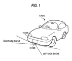
- the present invention relates to an apparatus for watching around a vehicle and more particularly to an apparatus for allowing a driver within a vehicle such as an automobile to observe scenes and the like on both left and right sides of the vehicle.
- JP-A-10-104765 have adopted as what marks off the left image from the right one by compounding each of the left and right images and a window type mask using a trimming image and as what limits a range of pick-up visual fields corresponding to the mask position.
- the mask area of a mask image has heretofore been displayed in a signal color such as black.
- the drawback is poor visibility in that though the boundary between the left and right images and the mask image is distinctly recognized because the left and right images are brightly displayed in the daytime time zone, a dark portion (black portion) of each of the left and right images becomes greater in a time zone where the outside of the vehicle is dark and this makes it difficult to clearly recognize the boundary between the left and right images and the mask image.
- an apparatus for watching around a vehicle of the sort mentioned above is used to watch around a vehicle by causing images around the vehicle to be displayed during the travel of the vehicle on narrow streets offering poor visibility.
- the display of such images becomes unnecessary during the travel of the vehicle offering unobstructed view. Therefore, it is needed to switch the on and off states of displaying images around the vehicle by the apparatus for watching around a vehicle.
- the first prior art develops a problem arising from troublesome operation of switching the on and off states of the display of images around the vehicle.
- JP 10-104765 discloses an apparatus according to the preamble part of claim 1.
- the luminance of a display unit is adjustable on the basis of a signal of an optocoupler for sensing the ambient brightness.
- Another object of the present invention is to provide an apparatus for watching around a vehicle by effectively preventing a noise image from being displayed on a display unit in order to improve display quality at the same time.
- Still another object of the present invention is to provide a low-cost apparatus for watching around a vehicle capable of switching the on and off states of the display of images around a vehicle precisely and automatically depending on the visibility around the vehicle.
- the apparatus for watching around a vehicle may function so as to pick up both left and right surroundings of the vehicle, causing the left and right images thus picked up to be displayed on the display unit separately or simultaneously, and also displaying the mask image in a manner specifying the left or right image.
- a plurality of colors including light and dark colors may be provided as the display color of the mask image, and the display color of the mask image may be switched to the dark color when the luminous intensity outside the vehicle is decided to be high through the light-to-dark decision signal, and to the light color when the luminous intensity outside the vehicle is decided to be low therethrough.
- the light-to-dark decision unit may have a lamp lighting circuit mounted on the vehicle, and the light-to-dark decision signal may include a light-on and a light-off signal of the lamp lighting circuit, thereby to switch the display colors of the mask image when the luminous intensity outside the vehicle is decided to be high by the light-off signal or when the luminous intensity outside the vehicle is decided to be low by the light-on signal.
- a means not forming part of the present invention may be devised of technically solving the foregoing problems by an apparatus for watching around a vehicle using an image pick-up element to be mounted in the vehicle to pick up images on both the left and right sides of the surroundings of the vehicle and displaying the left and right images thus picked up on a display unit provided within the vehicle via an image control unit
- the image control unit may comprises an image pick-up element power switch for turning on and off the operating circuit of the image pick-up element, an image output signal switch for turning on and off an image output circuit for subjecting an image signal picked up by the image pick-up element to a conversion process and supplying the converted image signal, and a switch control portion having the upper threshold speed of vehicle speed for turning on and off the image pick-up element power switch and a lower threshold speed of the vehicle speed for turning on and off the image output signal switch and wherein the image pick-up element power switch may be turned on by the switch control portion when it is detected that the vehicle speed reaches the upper threshold speed during the time of speed reduction and the image output signal switch
- the apparatus for watching around a vehicle may be such that the image pick-up element power switch as well as the image output signal switch is turned off by the switch control portion when it is detected that the vehicle speed reaches the lower threshold speed.
- the apparatus for watching around a vehicle may be such that the image control unit includes a display unit power switch for turning on and off the operating circuit of the display unit, wherein the display unit power switch and the image pick-up element power switch are turned on and off in synchronization with each other by the switch control portion.
- another apparatus not forming part of the present invention for watching around a vehicle by picking up images of dead angle areas around the vehicle to display the images within the vehicle comprises: an image pick-up unit for picking up images of dead angle areas around the vehicle; a display unit for displaying the images picked up by the image pick-up unit; a distance measuring unit for detecting the distance between the vehicle and an obstacle so positioned as to obstruct the view of a driver on at least one side out of both sides of the vehicle during the travel of the vehicle; and a controller for deciding whether or not the display of the image on the display unit will be needed on the basis of the distance detected by the distance measuring unit and controlling the display unit over switching the on and off states of display according to the decision made thereby.
- the apparatus for watching around a vehicle is such that the distance measuring unit detects the distance between the vehicle and each of the obstacles positioned on both the left and right sides of the vehicle during the travel of the vehicle; and the controller detects a space between the left- and right-hand obstacles on the basis of the distance between the vehicle and each of the left- and right-hand obstacles detected by the distance measuring unit, regards the space as width of a road on which the vehicle is traveling, decides whether or not the display of the image on the display unit will be needed on the basis of the value of the width thereof, and controls the display unit over switching the on and off states of display according to the decision made thereby.
- the apparatus for watching around a vehicle further comprises a travel-condition detector for accepting at least one vehicle signal for making reduced vehicle speed detectable out of vehicle signals indicating travel conditions which are output from a plurality of vehicle portions, and detecting the reduced vehicle speed according to the one vehicle signal, wherein the controller decides whether or not the display of the image on the display unit will be needed on the basis of the width of the road detected by the distance measuring unit and the result detected by the travel-condition detector, and controls the display unit over switching the on and off states of display according to the decision made thereby.
- a travel-condition detector for accepting at least one vehicle signal for making reduced vehicle speed detectable out of vehicle signals indicating travel conditions which are output from a plurality of vehicle portions, and detecting the reduced vehicle speed according to the one vehicle signal, wherein the controller decides whether or not the display of the image on the display unit will be needed on the basis of the width of the road detected by the distance measuring unit and the result detected by the travel-condition detector, and controls the display unit over switching the on and off states of display according to the decision
- the apparatus for watching around a vehicle further comprises a travel-condition detector for detecting vehicle speed by accepting a vehicle signal indicating vehicle speed, wherein the controller decides that the display of the image by the display unit will be needed only in case where the width of the road detected by the distance measuring unit is equal to a predetermined reference distance or less and where the vehicle speed detected by the travel-condition detector is a predetermined reference speed or lower, and causes the image to be displayed on the display unit.
- a travel-condition detector for detecting vehicle speed by accepting a vehicle signal indicating vehicle speed
- the apparatus for watching around a vehicle is such that the image pick-up unit is installed in the front end portion of the vehicle and used to pick up images in left and right directions in front of the vehicle.
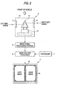
- an apparatus for watching around an automobile as a vehicle for example, comprises an image pick-up unit 3 installed beneath a front bumper or the like, a display unit 4 formed with an LCD (Liquid Crystal Display), a CRT or the like provided in a position on an instrument panel or the like within the vehicle where it is easily visible to a driver, an image signal processing portion 5 for converting the image signal picked up by the image pick-up unit 3 to a predetermined display signal and supplying to the display unit 4 the display signal, a mask addition processor 6 for adding (so-called superimposing) a predetermined mask image 16 by the image signal processing portion 5 onto the display signal and supplying the mask image 16 to the display unit 4, and a photodiode 7 as a light-to-darkness decision unit for detecting the luminous intensity outside the vehicle.
- an image pick-up unit 3 installed beneath a front bumper or the like
- a display unit 4 formed with an LCD (Liquid Crystal Display), a CRT or the like provided in a position on an instrument panel or
- the image pick-up unit 3 includes a rectangular case body 10 extending along the longitudinal direction of the automobile 1, a pair of lateral transmission windows 11 and 12 of transparent glass fitted to the rectangular opening formed and positioned on both the respective front side openings of the case body 10, a CCD camera 13 as a single image pick-up portion disposed in the case body 10, and a prism body 14 for guiding light onto the image pick-up surface of the CCD camera 13 by reflecting the light introduced through the transmission windows 11 and 12.
- the image signal picked up by the CCD camera 13 is subjected to a mirror image inversion process in the image signal processing portion 5 and supplied to the display unit 4.
- the predetermined mask image 16 is added thereto in the mask addition processor 16 and supplied to the display unit 4.
- the window frame type mask image 16 is displayed.
- the right-hand side scene picked up through the transmission window 12 is displayed in the right frame of the mask image 16, whereas the left-hand side scene picked up through the transmission window 11 is displayed in the left frame of the mask image 16.
- the left and right images are displayed on the right and left sides of the display unit 4 by the display unit 4.
- the mask addition processor 6 supports two kinds of display colors including blue as a light display color to be added to the mask image 16 and black as a dark display color to be added thereto. These colors are so controlled that they are switched according to a brightness signal as a light-to-darkness decision signal from the photodiode 7.
- a predetermined threshold value has been set as the brightness signal, for example, and in a case where the brightness signal has a threshold value or greater, the black color is added to the mask image 16. In a case where the brightness signal has a threshold value less than the threshold value, that is, the outside of the vehicle is dark and has not predetermined lightness, the light blue color is added to the mask image 16.
- the mask image 16 is provided with a plurality of display colors including blue and black. Then the photodiode 7 detects the lightness whereby to have a black mask image 16 added and displayed while the ambience is light in the daytime and to have a blue mask image 16 added and displayed while the ambience is dark at night. Consequently, irrespective of lightness outside the vehicle, the boundary between the picked-up left and right images and the mask image 16 is clearly recognized and this makes it possible to specifically distinguish between the left and right images. Thus, the visibility is improved.
- the mask image 16 of a two-stage switching structure including two kinds of black and blue display colors has been referred to according to this embodiment of the invention
- a system of automatically switching more than two stages with multicolors including various light and dark colors to be displayed on the mask image 16 depending on the outside luminous intensity may be adopted.
- any system of successively changing the brightness of the mask image 16 depending on the outside luminous intensity may also be adopted.
- a display color of the dark color system may be employed while the luminous intensity outside the vehicle is high, whereas a display color of the light color system may be employed while the luminous intensity outside the vehicle is low.
- the invention is so configured as to have the photodiode 7 as a light-to-dark decision unit for detecting the lightness outside the vehicle, any one of the luminous intensity detecting unit may be employed.
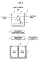
- Fig. 3 shows a second embodiment of the invention, wherein like reference characters designate like components in the first embodiment thereof.
- the second embodiment of the invention is so configured as to utilize a lamp lighting circuit 18 for a headlamp and a small lamp mounted on a vehicle in place of the photodiode 7 according to the first embodiment of the invention as the light-to-darkness decision unit for detecting the lightness outside the vehicle.
- ON/OFF of the lamp in the lamp lighting circuit 18, that is, a lamp-on or a lamp-off signal is used as the light-to-dark decision signal.
- the mask image 16 having the two kinds of blue and black display colors respectively as light and dark colors is so controlled as to switch the lamp-on and lamp-off signals.
- the black mask image 16 is added in a case where a signal from the lamp lighting circuit 18 is the light-off signal, that is, the outside of the vehicle has a predetermined lightness or greater as in the daytime and the lighting of the lamp is decided to be unnecessary.
- the light blue mask image 16 is added in a case where a signal from the lamp lighting circuit 18 is the light-on signal, that is, the outside of the vehicle is dark enough not to reach the predetermined lightness at night and the lighting of the lamp is decided to be necessary.
- the black mask image 16 is added and displayed in the daytime when the lighting of the lamp is unnecessary, whereas the light blue display color is added and displayed at night when the lighting of the lamp is necessary.
- the boundary between the picked-up left and right images and the mask image 16 is clearly recognized and this contributes to improving the visibility.
- the second embodiment of the invention is advantageous in that the lamp lighting circuit 18 installed in the vehicle is utilized without specially providing any photodiode 7, thus making the structure of the apparatus for watching around the vehicle can be simplified.
- the mask area of the mask image 16 has been formed like a window frame, it may be so configure as to provide left and right partitioned areas existing in the at least central portion even though any mask area does not exit along the outer periphery of each of the left and right images.
- each of embodiments of the invention teaches a structure wherein a so-called window frame type mask area to be synthesized into and displayed on the display unit 4 as the superimposed mask image 16, the picked-up left and right images may be displayed separately.
- the superimposed image 16 may be displayed with discriminating characters of (L) and (R) respectively designating left and right for specifying the left and right sides. Even in this case, the image individually displayed can be recognized as the right-side image or left-side one.
- pick-up unit for separately picking up left and right scenes may be provided.
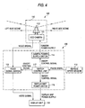
- an apparatus for watching around an automobile as a vehicle for example, comprises a camera unit 103 as an image pick-up unit installed beneath a front bumper or the like, a display unit 104 formed with an LCD, a CRT or the like provided in a position on an instrument panel or the like with the vehicle where it is easily visible to a driver, and an image control unit 105 for subjecting the image pick-up signal in the camera unit 103 to a conversion process and supplying the converted signal to the display unit 104.
- the camera unit 103 includes a rectangular case body 110 extending along the longitudinal direction of the automobile 101, a pair of lateral transmission windows 111 and 112 of transparent glass fitted to the rectangular opening formed and positioned on both the respective front side openings of the case body 110, a CCD camera 111 as a single image pick-up element disposed in the case body 110, and a prism body 112 for guiding light onto the image pick-up surface of the CCD camera 111 by reflecting the light introduced through the transmission windows 111 and 112.
- the image pick-up signal from the CCD camera 111 is subjected to a mirror image inversion process in the image control unit 105 and supplied to the display unit 104.
- the right-hand side scene picked up through the right transmission window is displayed in the right half portion of the display unit 104 as a right image, whereas the left-hand side scene picked up through the left transmission window is displayed in the left half portion thereof.
- the image control unit 105 includes a camera power switch 114 as the image pick-up element power switch for turning on and off the actuating circuit of the CCD camera 111, a video signal switch 115 as the image output signal switch for subjecting the image pick-up signal to a predetermined converting process and supplying the converted signal to the display unit 104 as video signal, a display unit power switch 116 for turning on and off the actuating circuit of the display unit 104, and a switch control portion 117 for controlling the on and off of the camera power switch 114, and the video signal switch 115 and the display unit power switch 116.
- a camera power switch 114 as the image pick-up element power switch for turning on and off the actuating circuit of the CCD camera 111
- a video signal switch 115 as the image output signal switch for subjecting the image pick-up signal to a predetermined converting process and supplying the converted signal to the display unit 104 as video signal
- a display unit power switch 116 for turning on and off the actuating circuit of the
- the switch control portion 117 there are set an upper threshold speed Va of the vehicle speed for controlling the on and off in synchronization with the on and off of the camera power switch 114, and a lower threshold speed Vb of the vehicle speed for controlling the on and off of the video signal switch 115; in this case, Va>Vb.
- the upper and lower threshold values Va and Vb may be set at 20 km/h and 10 km/h, respectively, on the assumption that while it takes one second or greater to reduce the vehicle speed from 20 km/h up to 10 km/h during traveling in an urban area, the operation of starting the CCD camera 111 as well as the display unit 104 is sufficiently stably performable within that time.
- the switch control portion 117 also functions as what decides whether the vehicle speed will be increased or decreased by detecting a pulse signal corresponding to the vehicle speed via a vehicle speed sensor 119 of the vehicle and calculating the vehicle speed from the period of the signal.
- Step S1 it is decided whether or not the present vehicle speed will be higher than the upper threshold speed Va (Step S1). In case where the former is higher than the latter, Step S2 is followed. Then the camera power switch 114, the video signal switch 115 and the display unit power switch 116 are held OFF.
- Step S3 is followed and an ON control signal is applied from the switch control portion 117 to each of the camera power switch 114 and the display unit power switch 116.
- the camera power switch 114 and the display unit power switch 116 are controlled so that both may be turned on in synchronization with each other.
- the video signal switch 115 are held OFF. Consequently, the video signals of the left and right images picked up by the CCD camera 111 are not applied to the display unit 104 at this time, whereupon no images are displayed on the display unit 104.
- Step S4 is followed and whether or not the vehicle speed V will be higher than the lower threshold speed Vb is decided and in case where the former is higher than the latter, Step S3 is followed again.
- Step S5 is followed and while the camera power switch 114 and the display unit power switch 116 are both held ON, the ON control signal is applied from the switch control portion 117 to the video signal switch 115, whereby the video signal switch 115 is turned on.
- the video signals of the left and right images are applied to the display unit 104 and the left and right images are simultaneously display on the display unit 104.
- the driver is allowed to confirm safety on the left and right sides within the intersection zone all at once by looking at the display portion of the display unit 104; thus, safety is easily confirmable.
- Step S11 it is decided whether or not the present vehicle speed will be lower than the lower threshold speed Vb (Step S11).
- Step S12 is followed.
- the camera power switch 114, the video signal switch 115 and the display unit power switch 116 are held ON, so that the left and right images are being displayed.
- Step S13 is followed and an OFF control signal is applied from the switch control portion 117 to each of the display unit power switch 16 and the video signal switch 115.
- the camera power switch 114, the display unit power switch 116, and the video signal switch 115 are controlled so that they may be turned off in synchronization with one another. Then the display of the left and right images on the display unit 104 is stopped.
- the vehicle speed is reduced from the normal travel condition to the upper threshold speed Va or lower, the power is supplied to turn on the CCD camera 111 and the display unit 104.
- the video signal switch 115 is then turned on in this system. As a noise image due to image disturbance at the initial stage of the rise of the CCD camera 111 is effectively prevented from being displayed and display quality is made improvable.
- Step S23 it is decided whether or not a preset fixed time (ex., about one second) necessary for stabilizing the operation of the CCD camera 111 and the display unit 104 will be passed ((Step S23).
- a preset fixed time ex., about one second
- Stpe S24 is followed and after the camera power switch 114 and the display unit power switch are both turned on, the ON control signal is applied from the switch control portion 117 to the video signal switch 115 so as to hold ON the video signal switch 115.
- the ideo signals of the left and right signals picked up by the CCD camera 111 are applied to the display unit 104, so that the left and right images are simultaneously displayed on the display unit 104.
- a CCD camera 111 for taking in the left and right scenes of images may be so arranged as to be disposed on both left and right sides separately.
- the upper and lower threshold speeds Va and Vb may properly be set in order to secure a time necessary for stabilizing the operation of the CCD camera 111 as well as the display unit 104.
- the display unit 104 may be turned on and off independently. In this case, it is only needed to hold ON the display unit 104 beforehand. The rest of the operations may be performed as shown in Figs. 5 and 6.
- Fig. 8 is a block diagram showing the configuration of another apparatus for watching around a vehicle not forming part of the present invention.
- Figs. 9 and 10 are diagrams each showing the travel-condition of a vehicle on a road with the apparatus for watching around a vehicle of Fig. B.
- the apparatus for watching around a vehicle comprises a camera (an image pick-up unit) 201, a display (a display unit) 203, a distance measuring sensor (a distance measuring unit) 205, a travel-condition detecting portion (a travel-condition detector) 207, a power switch 209, and a control unit (a controller) 211.
- the camera 201 is installed in the front end portion of the vehicle and used to pick up images in image pick-up areas (dead angle areas) 213 and 215 on the left and right sides in front of the vehicle.
- the display 203 is installed in a position visible to a driver in the vehicle and used to display the image picked up by the camera 201 or a car navigation image in case where the vehicle is equipped with a car navigation unit.
- the power switch 209 is a switch for turning on and off the apparatus for watching around a vehicle.
- the distance measuring sensor 205 is installed on both the left and right sides of the front end portion of the vehicle and used to detect not only the presence or absence of obstacles on both the left and right sides of a road 221 during the travel of the vehicle but also distances up to the respective obstacles 223 and 225 by means of a distance measuring signal (ultrasonic wave in this case) 217 under the control of the control unit 211.
- the distance measuring sensors 205 also supplies the detected results to the control unit 211.
- the ultrasonic wave is used as a distance measuring signal 217.
- Each of the left and right distance measuring sensors 205 periodically transmits the ultrasonic wave 217 in the lateral directions of the vehicle and receives the reflected wave.
- each of the left and right distance measuring sensors 205 also detects the presence or absence of the reflected wave and the passage of time from the transmission of the ultrasonic wave 217 up to the reception thereof, so that it detects not only the presence or absence of the obstacles 223 and 225 on the left and right sides of the road 221 during the travel of the vehicle but also the distances up to the respective obstacles 223 and 225.
- the obstacles 223 and 225 as objects for detection include those which are so erected as to obstruct the view of the driver such as buildings, walls and the like.
- the travel-condition detecting portion 207 accepts at least one vehicle signal (e.g., vehicle speed signal or brake signal) out of the vehicle signals indicating the travel condition that is output from each portion of the vehicle (e.g., the presence of absence of the vehicle speed and the operation of the brake) and supplies the detected result to the control unit 211.
- vehicle signal e.g., vehicle speed signal or brake signal
- the travel-condition detecting portion 207 is used for accepting a vehicle speed signal that is output from vehicle speed sensors (not shown) mounted in the vehicle, detecting the vehicle speed based on the vehicle speed signal and supplying the detected result to the control unit 211.
- the control unit 211 decides whether or not the display of the image picked up by the camera 201 will be needed on the basis of the results detected by the distance measuring sensors 205 and the travel-condition detecting portion 207.
- the control unit 211 also functions as what causes the image picked up by the camera 201 to be displayed on the display 203 according to the decided results. Further, the control unit 211 causes any other image such as a navigation image or the like to be displayed on the display 203 as occasion demands unless the image picked up by the camera 201 is displayed on the display 203.
- the control unit 211 decides that the display of the image picked up by the camera 201 will be needed and turns on the display 203 so that the image picked up by the camera 201 may be displayed thereon.
- Fig. 11 is a flowchart (subroutine) showing the principal control contents of the control unit 211.
- Step S1 a degree of unobstructed view on the left and right sides of the road 221 during the travel of the vehicle is detected via the distance measuring sensor 205 and then Step S2 is followed.
- Step S1 the presence or absence of obstacles 223 and 225 so positioned as to obstruct the view of the driver on the left and right sides of the road 221 during the travel of the vehicle as well as the width of the road during the travel of the vehicle is detected via the distance measuring sensors 205.
- Step S3 it is decided whether a lateral vista of the road 221 is good or bad on the basis of the detected results at Step S1. In case where the results are bad, Step S3 is followed, whereas the results are not bad, the display of the image picked up by the camera 201 is decided to be unnecessary and Step S5 is followed.
- the obstacles 223 and 225 so positioned as to obstruct the view of the driver on the left and right sides of the road 221 during the travel of the vehicle exist at Step S3.
- the field of vision is decided to be bad.
- the field of vision is decided to be good.
- Step S3 it is decided whether or not the vehicle speed will be the predetermined reference speed or lower on the basis of the result detected by the travel-condition detecting portion 207.
- the display of the image picked by the camera 201 on the display 203 is decided to be necessary and Step S4 is followed.
- Step S5 the display of the image picked up by the camera 201 on the display 203 is decided to be unnecessary and Step S5 is followed.
- the reason for deciding whether or not the vehicle speed will be the reference speed or lower at Step S3 is as follows. Even in case where the road 221 offers poor visibility on the left and right sides during the travel of the vehicle, the vehicle speed is often set at the value of the reference speed or greater with respect the road 221 free from branching points such as crossroads and the like, and free from fear of colliding with any other vehicle coming from the left or right side thereof (i.e., the display of the image picked up by the camera 201 is unnecessary).
- the vehicle speed is often set at the reference speed or lower since the driver will have to drive the vehicle while watching around the left and right sides of the road 221.
- Step S4 the image picked up by the camera 201 is displayed on the display 203 and the next processing is performed.
- the image displayed on the display 203 is switched to the image picked up by the camera 203 in case where any other image such as a car navigation image or the like has been displayed on the display 203 at that point of time.
- Step S5 it is decided whether or not the image picked up by the camera 201 has been displayed on the display 203 and in case where it has been displayed, Step S6 is followed. In case where it has not been displayed, the next processing is performed.
- Step S6 the preceding image displayed by the display 203 is displayed on the display 203 before the image picked up by the camera 201 is displayed on the display 203 and the next processing is performed.
- control unit 211 controls the contents of display on the display 203 by repeating the processing from Step S1 up to Step S6 at high speed.
- the display of images around the vehicle on the display 203 is decided to be necessary only when the width of the road 221 during the travel of the vehicle has the predetermined reference distance or less and only when the vehicle speed is the reference speed or lower, and the images around the vehicle are displayed on the display 203. Accordingly, only in case where the width of the road 221 is narrow and where the driver lowers the vehicle speed in order to watch around the vehicle, the images around the vehicle are allowed to be displayed on the display 203.
- the display of images around the vehicle can be made automatically and precisely with a low-cost construction in proportion to a visual field over the surroundings of a road and the travel conditions of the vehicle. As a result, images around the vehicle are prevented from being displayed in any useless place, which also prevents the interruption of driving.
- the left and right sides can precisely be confirmed at cross-shaped and T-shaped intersections by reference to the images picked up by the camera 201.
- the travel-condition detecting portion 207 is to accept the vehicle speed signal as the vehicle signal so as to detect the vehicle speed according to the above description, the travel-condition detecting portion 207 may be used to detect whether or not the brake is actuated by inputting thereto the brake signal indicating the actuation of the brake as the vehicle signal.
- control unit 211 is set to decide that the display of the image picked up by the camera 201 on the display 203 will be needed and to turn on the display 203 so as to display the image picked up by the camera 201 only in case where the width of the road 21 detected via the distance measuring sensor 5 is equal to the predetermined reference distance or less; the actuation of the brake is detected by the travel-condition detecting portion 207; and the vehicle speed detected by the travel-condition detecting portion 207 is the predetermined reference speed (e.g., 10 km/h) or lower.
- predetermined reference speed e.g. 10 km/h
- a changeover switch may be provided, so that switching the on and off states of the display of the image picked up by the camera 201 on the display 203 is conducted manually.
- switching the on and off states of the display of the image picked up by the camera 201 on the display 203 may be conducted, irrespective of the decision on whether or not the display of the image picked up by the camera 201 on the part of the control unit 211.
- the apparatus for watching around the vehicle includes the light-to-dark decision unit for deciding the lightness outside the vehicle; the display color of the mask image is switchable from one to another; and the display color of the mask image is set switchable from one to another according to the light-to-dark decision signal from the light-to-dark decision unit, whereby the boundary between the picked-up images and the mask image can clearly be recognized; the advantage is that this contributes to improving the visibility.
- the apparatus for watching around a vehicle functions as to pick up images of both left and right surroundings of the vehicle, causing the left and right images thus picked up to be displayed on the display unit separately or simultaneously; the advantage is that the picked-up left image can easily be distinguished from the right image by the mask image in a manner specifying the left or right image.
- the apparatus for watching around a vehicle is such that a plurality of colors including light and dark colors are provided as the display color of the mask image and wherein the display color of the mask image is switched to the dark color when the luminous intensity outside the vehicle is decided to be high through the light-to-dark decision signal, and to the light color when the luminous intensity outside the vehicle is decided to be low therethrough, so that the boundary between the picked-up left and right images and the mask image can clearly be recognized and this results in improving the visibility.
- the boundary between the picked-up images and the mask image can clearly be recognized, irrespective of the lightness outside the vehicle. Therefore, the advantage is that not only improvement in the visibility but also structural simplification is achievable.
- the image control unit comprises an image pick-up element power switch for turning on and off the operating circuit of the image pick-up element, an image output signal switch for turning on and off an image output circuit for subjecting an image signal picked up by the image pick-up element to a conversion process and supplying the converted image signal, and a switch control portion having the upper threshold speed of vehicle speed for turning on and off the image pick-up element power switch and a lower threshold speed of the vehicle speed for turning on and off the image output signal switch and wherein the image pick-up element power switch may be turned on by the switch control portion when it is detected that the vehicle speed reaches the upper threshold speed during the time of speed reduction and the image output signal switch is turned on by the switch control portion when it is detected that the vehicle speed reaches the lower threshold speed during the time of speed reduction.
- the advantage is that it is possible to achieve power saving effectively.
- the image control unit includes the display unit power switch for turning on and off the operating circuit of the display unit simultaneously with the display unit power switch and the image pick-up element power switch being turned on and off in synchronization with each other by the switch control, portion, the advantage is that it is possible to achieve larger power saving.
- the apparatus for watching around a vehicle is provided with the distance measuring unit for detecting the distance between the vehicle and the obstacle so positioned as to obstruct the view of the driver on at least one side out of both sides of the vehicle during the travel of the vehicle, and the controller for deciding whether or not the display of the image on the display unit will be needed on the basis of the distance detected by the distance measuring unit and controlling the display unit over switching the on and off states of display according to the decision made thereby.
- the display of images around the vehicle can be made automatically and precisely with a low-cost construction in proportion to a visual field over the surroundings of a road and the travel conditions of the vehicle. As a result, images around the vehicle are prevented from being displayed in any useless place, which also prevents the interruption of driving.
- switching the on and off states of the display of images around the vehicle can be conducted precisely in proportion to the width of a road in the urban area where buildings and the like are erected close to both sides of the road.
- the controller Since how much the driver feels the necessity of visibility around the vehicle is typically represented by the vehicle speed and the variation of the vehicle speed (i.e., speed is reduced when visibility of the surroundings is needed), the controller is made to decide whether or not the display of the image on the display unit will be needed on the basis of the width of the road detected by the distance measuring unit and the result detected by the travel-condition detector, and able to control the display unit over switching the on and off states of display by taking into consideration the visibility around the road and the necessity of visibility around the vehicle that the driver desires.
- the display of the image by the display unit since the display of the image by the display unit is decided to be necessary only in case where the width of the road detected by the distance measuring unit is equal to the predetermined reference distance or less and where the vehicle speed detected by the travel-condition detector is the predetermined reference speed or lower, the image around the vehicle is displayed on the display unit. Therefore, the image around the vehicle can be displayed on the display unit only when the width of the road is narrow and when the driver lowers the vehicle speed so as to watch around the vehicle.
- the image pick-up unit is installed in the front end portion of the vehicle and used to pick up images in left and right directions in front of the vehicle, the left and right sides can precisely be confirmed at cross-shaped and T-shaped intersections by reference to the images picked up by the camera.
Claims (4)
- Vorrichtung zum Blicken um ein Fahrzeug herum, mit:einer außen an dem Fahrzeug montierten Bildaufnahmeeinheit (3) zum Aufnehmen von Bildern der Umgebung des Fahrzeugs (1); undeiner innerhalb des Fahrzeug vorgesehenen Anzeigeeinheit (4) zum Anzeigen der Bilder mit einer über die Bilder gelegten Bildmaske (16),dadurch gekennzeichnet, dassdie Vorrichtung ferner eine Hell/Dunkel-Entscheidungseinheit (7) zum Entscheiden einer Helligkeit auerhalb des Fahrzeugs und Ausgeben eines Hell/Dunkel-Entscheidungsignals aufweist;eine Anzeigefarbe der Bildmaske (16) von einer zu einer anderen umschaltbar ist; unddie Anzeigefarbe der Bildmaske (16) gemäß dem Hell/Dunkel-Entscheidungssignal aus der Hell/Dunkel-Entscheidungseinheit (7) von einer zu einer anderen umschaltbar festgelegt ist.
- Vorrichtung gemäß Anspruch 1, dadurch gekennzeichnet, dass
die Bildaufnahmeeinheit (3) sowohl eine rechte als auch eine linke Umgebung des Fahrzeugs (1) aufnimmt, um linke und rechte Bilder zu erhalten;
die Anzeigeeinheit (4) linke und rechte Bilder getrennt oder gleichzeitig anzeigt; und
die Anzeigeeinheit (4) die Bildmaske (16) anzeigt, um linke und rechte Bilder anzugeben. - Vorrichtung gemäß Anspruch 1, dadurch gekennzeichnet, dass
eine Mehrzahl von Farben einschließlich heller und dunkler Farben als die Anzeigefarben der Bildmaske (16) vorgesehen sind; und
die Anzeigefarbe der Bildmaske (16) auf die dunklen Farbe umgeschaltet wird, wenn auf der Grundlage des Hell/Dunkel-Entscheidungsignals entschieden wird, dass die Leuchtintensität außerhalb des Fahrzeugs hoch ist, und auf die helle Farbe, wenn auf dieser Grundlage entschieden wird, dass die Leuchtintensität außerhalb des Fahrzeugs niedrig ist. - Vorrichtung gemäß Anspruch 3, dadurch gekennzeichnet, dass die Hell/Dunkel-Entscheidungseinheit eine an dem Fahrzeug angebrachte Lampenerleuchtungsschaltung (18) aufweist, wobei das Hell/Dunkel-Entscheidungsignal ein Licht-an- und ein Licht-aus-Signal der Lampenerleuchtungsschaltung (18) aufweist, um die Anzeigefarbe der Bildmaske (16) umzuschalten, wenn durch das Licht-aus-Signal entschieden wird, dass die Leuchtintensität außerhalb des Fahrzeugs hoch ist, oder wenn durch das Licht-an-Signal entschieden wird, dass die Leuchtintensität außerhalb des Fahrzeugs niedrig ist.
Applications Claiming Priority (6)
| Application Number | Priority Date | Filing Date | Title |
|---|---|---|---|
| JP2000056873A JP3764317B2 (ja) | 2000-03-02 | 2000-03-02 | 車載用周辺視認装置 |
| JP2000056873 | 2000-03-02 | ||
| JP2000070309A JP2001253295A (ja) | 2000-03-14 | 2000-03-14 | 車載用周辺視認装置 |
| JP2000070309 | 2000-03-14 | ||
| JP2000132135A JP2001315575A (ja) | 2000-05-01 | 2000-05-01 | 車両周辺視認装置 |
| JP2000132135 | 2000-05-01 |
Publications (3)
| Publication Number | Publication Date |
|---|---|
| EP1129904A2 EP1129904A2 (de) | 2001-09-05 |
| EP1129904A3 EP1129904A3 (de) | 2004-05-26 |
| EP1129904B1 true EP1129904B1 (de) | 2006-08-09 |
Family
ID=27342563
Family Applications (1)
| Application Number | Title | Priority Date | Filing Date |
|---|---|---|---|
| EP01105183A Expired - Lifetime EP1129904B1 (de) | 2000-03-02 | 2001-03-02 | Überwachungseinrichtung für schwer einsehbare Zonen um Kraftfahrzeuge |
Country Status (3)
| Country | Link |
|---|---|
| US (1) | US6400405B2 (de) |
| EP (1) | EP1129904B1 (de) |
| DE (1) | DE60122040T8 (de) |
Cited By (1)
| Publication number | Priority date | Publication date | Assignee | Title |
|---|---|---|---|---|
| CN101827727B (zh) * | 2007-11-19 | 2012-07-18 | 丰田自动车株式会社 | 车辆周边监视系统和车辆足部照明系统 |
Families Citing this family (40)
| Publication number | Priority date | Publication date | Assignee | Title |
|---|---|---|---|---|
| US6657176B2 (en) * | 2000-04-12 | 2003-12-02 | Autonetworks Technologies, Ltd. | On-vehicle image pick-up apparatus and method of setting image pick-up direction |
| DE10107345A1 (de) * | 2001-02-12 | 2002-08-29 | Siemens Ag | Mobile Telekommunikationseinrichtung |
| DE10138719A1 (de) * | 2001-08-07 | 2003-03-06 | Siemens Ag | Verfahren und Vorrichtung zur Darstellung von Fahrhinweisen, insbesondere in Auto-Navigationssystemen |
| US7253833B2 (en) * | 2001-11-16 | 2007-08-07 | Autonetworks Technologies, Ltd. | Vehicle periphery visual recognition system, camera and vehicle periphery monitoring apparatus and vehicle periphery monitoring system |
| US6809704B2 (en) * | 2002-02-08 | 2004-10-26 | Charles J. Kulas | Reduction of blind spots by using display screens |
| JP4195966B2 (ja) * | 2002-03-05 | 2008-12-17 | パナソニック株式会社 | 画像表示制御装置 |
| US6968266B2 (en) * | 2002-04-30 | 2005-11-22 | Ford Global Technologies, Llc | Object detection in adaptive cruise control |
| US20030214584A1 (en) * | 2002-05-14 | 2003-11-20 | Ross Bruce Eliot | Side and rear vision enhancement for vehicles |
| JP3793487B2 (ja) * | 2002-07-12 | 2006-07-05 | ナイルス株式会社 | 撮像システム |
| JP4005456B2 (ja) * | 2002-09-10 | 2007-11-07 | 株式会社オートネットワーク技術研究所 | カメラ装置及び車両周辺視認装置 |
| JP4299036B2 (ja) * | 2003-03-31 | 2009-07-22 | シャープ株式会社 | 車両用監視装置 |
| JP4244684B2 (ja) * | 2003-04-10 | 2009-03-25 | 三菱自動車工業株式会社 | 車両用監視装置 |
| JP4247066B2 (ja) * | 2003-08-01 | 2009-04-02 | 株式会社オートネットワーク技術研究所 | 車両周辺視認装置 |
| JP2005067531A (ja) * | 2003-08-27 | 2005-03-17 | Denso Corp | 車両用空調装置 |
| US7222019B2 (en) * | 2004-01-14 | 2007-05-22 | Yamaha Hatsudoki Kabushiki Kaisha | Vehicle image display apparatus and vehicle having the same |
| JP4510019B2 (ja) * | 2004-02-20 | 2010-07-21 | シャープ株式会社 | 車両用表示装置、車両、表示方法、画像表示プログラム、および記録媒体 |
| US7119951B2 (en) * | 2004-09-07 | 2006-10-10 | Corning Incorporated | Polarizer for high-power deep UV radiation |
| JP4606336B2 (ja) * | 2005-02-21 | 2011-01-05 | 株式会社オートネットワーク技術研究所 | 車両周辺視認装置 |
| US8130269B2 (en) * | 2005-03-23 | 2012-03-06 | Aisin Aw Co., Ltd. | Visual recognition apparatus, methods, and programs for vehicles |
| JP4566822B2 (ja) * | 2005-05-24 | 2010-10-20 | 本田技研工業株式会社 | 車両用画像表示装置 |
| US7365300B2 (en) * | 2005-06-29 | 2008-04-29 | Visteon Global Technologies, Inc. | Rear vision system |
| FR2891968B1 (fr) * | 2005-10-12 | 2008-01-18 | Valeo Electronique Sys Liaison | Systeme de communication entre une unite d'acquisition d'images video et un ordinateur de bord pour un vehicule automobile |
| JP4254887B2 (ja) * | 2006-07-06 | 2009-04-15 | 日産自動車株式会社 | 車両用画像表示システム |
| DE102007027756A1 (de) * | 2007-06-16 | 2008-12-18 | Bayerische Motoren Werke Aktiengesellschaft | Verfahren zur Unterstützung eines Fahrers eines Kraftfahrzeugs bei der Durchfahrt des Kraftfahrzeugs durch eine Engstelle und/oder zum Einhalten eines Sicherheitsabstandes zum Vorderfahrzeug |
| US20100265100A1 (en) * | 2009-04-20 | 2010-10-21 | Lsi Industries, Inc. | Systems and methods for intelligent lighting |
| DE102009050519A1 (de) * | 2009-10-23 | 2011-04-28 | Bayerische Motoren Werke Aktiengesellschaft | Verfahren zur Fahrerinformation |
| TWM403662U (en) * | 2010-07-02 | 2011-05-11 | Pixart Imaging Inc | Sensing device and its image sensing module |
| KR101232308B1 (ko) * | 2010-11-25 | 2013-02-13 | 에스엘 주식회사 | 헤드램프 제어장치 및 제어방법 |
| US20120249342A1 (en) * | 2011-03-31 | 2012-10-04 | Koehrsen Craig L | Machine display system |
| CA2808461C (en) * | 2011-06-07 | 2015-12-08 | Komatsu Ltd. | Perimeter monitoring device for work vehicle |
| US20140139669A1 (en) | 2012-01-30 | 2014-05-22 | Steven Petrillo | System and method for providing front-oriented visual information to vehicle driver |
| US9511711B2 (en) | 2012-01-30 | 2016-12-06 | Klear-View Camera, Llc | System and method for providing front-oriented visual information to vehicle driver |
| CA2885177C (en) * | 2012-08-16 | 2021-04-20 | Klear-View Camera, Llc | System and method for providing front-oriented visual information to vehicle driver |
| DE102015002923B4 (de) | 2015-03-06 | 2023-01-12 | Mekra Lang Gmbh & Co. Kg | Anzeigeeinrichtung für ein Fahrzeug insbesondere Nutzfahrzeug |
| JP6568603B2 (ja) * | 2016-01-28 | 2019-08-28 | 鴻海精密工業股▲ふん▼有限公司 | 車両用画像表示システム及びその画像表示システムを搭載した車両 |
| DE112016006950T5 (de) * | 2016-06-09 | 2019-02-21 | Mitsubishi Electric Corporation | Anzeigesteuervorrichtung, Anzeigevorrichtung, fahrzeuginternes Anzeigesystem und Anzeigesteuerverfahren |
| JP6597518B2 (ja) | 2016-08-15 | 2019-10-30 | 株式会社デンソー | 情報処理装置及びプログラム |
| US10574908B2 (en) * | 2016-11-08 | 2020-02-25 | Toyota Motor Engineering & Manufacturing North America, Inc. | Systems, vehicles, and methods for automatically displaying image data when a vehicle is located on an on-ramp to a roadway |
| US10755571B1 (en) * | 2019-03-01 | 2020-08-25 | Amazon Technologies, Inc. | Identifying parking location using single camera reverse projection |
| US11210946B2 (en) * | 2019-07-15 | 2021-12-28 | Verizon Patent And Licensing Inc. | Content sharing between vehicles based on a peer-to-peer connection |
Family Cites Families (11)
| Publication number | Priority date | Publication date | Assignee | Title |
|---|---|---|---|---|
| US5303205A (en) * | 1990-02-26 | 1994-04-12 | Trend Tec Inc. | Vehicular distance measuring system with integral mirror display |
| US5670935A (en) * | 1993-02-26 | 1997-09-23 | Donnelly Corporation | Rearview vision system for vehicle including panoramic view |
| DE4336288C1 (de) * | 1993-10-25 | 1995-03-30 | Daimler Benz Ag | Einrichtung zur Überwachung des Rück- bzw. Frontraumes eines einparkenden Kraftfahrzeugs |
| DE4409777A1 (de) * | 1994-03-22 | 1995-09-28 | Vdo Schindling | Einrichtung zur Steuerung der Leuchtdichte einer Anzeigevorrichtung in einem Kraftfahrzeug |
| JPH09244003A (ja) * | 1996-03-13 | 1997-09-19 | Toyota Motor Corp | 車両用画面制御装置 |
| JP3475664B2 (ja) * | 1996-08-07 | 2003-12-08 | 住友電装株式会社 | 画像表示装置 |
| JP3460472B2 (ja) * | 1996-10-01 | 2003-10-27 | 日産自動車株式会社 | 車両用カメラ |
| DE19754249B4 (de) * | 1997-12-06 | 2005-05-19 | Volkswagen Ag | Verfahren und Vorrichtung zur optischen Rangierhilfe für ein Kraftfahrzeug |
| EP1408693A1 (de) * | 1998-04-07 | 2004-04-14 | Matsushita Electric Industrial Co., Ltd. | Bildanzeigegerät an Bord eines Fahrzeugs, Bildsendersystem, -sendegerät und -aufnahmegerät |
| JP3511892B2 (ja) * | 1998-05-25 | 2004-03-29 | 日産自動車株式会社 | 車両用周囲モニタ装置 |
| JP2000222697A (ja) * | 1999-01-28 | 2000-08-11 | Sharp Corp | 車載カメラ装置 |
-
2001
- 2001-03-02 DE DE60122040T patent/DE60122040T8/de active Active
- 2001-03-02 US US09/796,485 patent/US6400405B2/en not_active Expired - Fee Related
- 2001-03-02 EP EP01105183A patent/EP1129904B1/de not_active Expired - Lifetime
Cited By (1)
| Publication number | Priority date | Publication date | Assignee | Title |
|---|---|---|---|---|
| CN101827727B (zh) * | 2007-11-19 | 2012-07-18 | 丰田自动车株式会社 | 车辆周边监视系统和车辆足部照明系统 |
Also Published As
| Publication number | Publication date |
|---|---|
| US20010028393A1 (en) | 2001-10-11 |
| EP1129904A2 (de) | 2001-09-05 |
| EP1129904A3 (de) | 2004-05-26 |
| DE60122040D1 (de) | 2006-09-21 |
| US6400405B2 (en) | 2002-06-04 |
| DE60122040T2 (de) | 2007-03-08 |
| DE60122040T8 (de) | 2007-08-23 |
Similar Documents
| Publication | Publication Date | Title |
|---|---|---|
| EP1129904B1 (de) | Überwachungseinrichtung für schwer einsehbare Zonen um Kraftfahrzeuge | |
| EP1400410B1 (de) | Fahrassistenzsystem für Fahrzeuge | |
| US6538622B1 (en) | Display apparatus on a vehicle | |
| EP1452390B1 (de) | Vorrichtung und Verfahren zur Überwachung der nahen Umgebung eines Fahrzeuges | |
| EP0795433A1 (de) | Steuervorrichtung eines Bildschirms in einem Wagen | |
| JP2001006097A (ja) | 車両の運転支援装置 | |
| JP2008222153A (ja) | 合流支援装置 | |
| JP2000207696A (ja) | 車載カメラ装置 | |
| US8334904B2 (en) | Vehicle surroundings monitoring system and vehicle foot illuminating system | |
| EP1043191A1 (de) | Rückblickeinrichtung für ein Fahrzeug | |
| CN113448096B (zh) | 车辆用显示装置 | |
| JP3739269B2 (ja) | 車両運転支援装置 | |
| EP1312506B1 (de) | Fahrerassistenz-Methode und -Verfahren bei Kfz-Spurwechselverfahren | |
| JP2002362270A (ja) | 運転支援装置 | |
| JP3764317B2 (ja) | 車載用周辺視認装置 | |
| JPH07215130A (ja) | 車載カメラ切り換え装置 | |
| JP2001071790A (ja) | 車両の表示装置 | |
| JP3898056B2 (ja) | 車両周辺監視システム | |
| JPH0958343A (ja) | 車両のノーズビュー装置 | |
| JP3468661B2 (ja) | 車両用周辺視認装置 | |
| JPH08276805A (ja) | 後方車両検出装置 | |
| JP2005135203A (ja) | 車両運転支援装置 | |
| JP2001253295A (ja) | 車載用周辺視認装置 | |
| JP2003276506A (ja) | 車両周辺監視装置 | |
| JP2009220674A (ja) | カメラシステム、点灯制御方法 |
Legal Events
| Date | Code | Title | Description |
|---|---|---|---|
| PUAI | Public reference made under article 153(3) epc to a published international application that has entered the european phase |
Free format text: ORIGINAL CODE: 0009012 |
|
| AK | Designated contracting states |
Kind code of ref document: A2 Designated state(s): AT BE CH CY DE DK ES FI FR GB GR IE IT LI LU MC NL PT SE TR |
|
| AX | Request for extension of the european patent |
Free format text: AL;LT;LV;MK;RO;SI |
|
| RIC1 | Information provided on ipc code assigned before grant |
Ipc: 7B 60Q 1/48 B Ipc: 7B 60R 1/00 A |
|
| PUAL | Search report despatched |
Free format text: ORIGINAL CODE: 0009013 |
|
| AK | Designated contracting states |
Kind code of ref document: A3 Designated state(s): AT BE CH CY DE DK ES FI FR GB GR IE IT LI LU MC NL PT SE TR |
|
| AX | Request for extension of the european patent |
Extension state: AL LT LV MK RO SI |
|
| 17P | Request for examination filed |
Effective date: 20040721 |
|
| AKX | Designation fees paid |
Designated state(s): DE |
|
| GRAP | Despatch of communication of intention to grant a patent |
Free format text: ORIGINAL CODE: EPIDOSNIGR1 |
|
| GRAS | Grant fee paid |
Free format text: ORIGINAL CODE: EPIDOSNIGR3 |
|
| GRAA | (expected) grant |
Free format text: ORIGINAL CODE: 0009210 |
|
| AK | Designated contracting states |
Kind code of ref document: B1 Designated state(s): DE |
|
| REF | Corresponds to: |
Ref document number: 60122040 Country of ref document: DE Date of ref document: 20060921 Kind code of ref document: P |
|
| PLBE | No opposition filed within time limit |
Free format text: ORIGINAL CODE: 0009261 |
|
| STAA | Information on the status of an ep patent application or granted ep patent |
Free format text: STATUS: NO OPPOSITION FILED WITHIN TIME LIMIT |
|
| 26N | No opposition filed |
Effective date: 20070510 |
|
| PGFP | Annual fee paid to national office [announced via postgrant information from national office to epo] |
Ref country code: DE Payment date: 20100312 Year of fee payment: 10 |
|
| PG25 | Lapsed in a contracting state [announced via postgrant information from national office to epo] |
Ref country code: DE Free format text: LAPSE BECAUSE OF NON-PAYMENT OF DUE FEES Effective date: 20111001 |
|
| REG | Reference to a national code |
Ref country code: DE Ref legal event code: R119 Ref document number: 60122040 Country of ref document: DE Effective date: 20111001 |