EP1123851B1 - Schienenfahrzeug, insbesondere Strassen- oder Stadtbahnwagen für den Nahverkehr - Google Patents
Schienenfahrzeug, insbesondere Strassen- oder Stadtbahnwagen für den Nahverkehr Download PDFInfo
- Publication number
- EP1123851B1 EP1123851B1 EP01102460A EP01102460A EP1123851B1 EP 1123851 B1 EP1123851 B1 EP 1123851B1 EP 01102460 A EP01102460 A EP 01102460A EP 01102460 A EP01102460 A EP 01102460A EP 1123851 B1 EP1123851 B1 EP 1123851B1
- Authority
- EP
- European Patent Office
- Prior art keywords
- rail
- vehicle
- level
- apron
- gap
- Prior art date
- Legal status (The legal status is an assumption and is not a legal conclusion. Google has not performed a legal analysis and makes no representation as to the accuracy of the status listed.)
- Expired - Lifetime
Links
- 239000000725 suspension Substances 0.000 claims abstract description 4
- 206010012411 Derailment Diseases 0.000 description 1
- 239000011248 coating agent Substances 0.000 description 1
- 238000000576 coating method Methods 0.000 description 1
- 238000005259 measurement Methods 0.000 description 1
- 239000007779 soft material Substances 0.000 description 1
Images


Classifications
-
- B—PERFORMING OPERATIONS; TRANSPORTING
- B61—RAILWAYS
- B61D—BODY DETAILS OR KINDS OF RAILWAY VEHICLES
- B61D17/00—Construction details of vehicle bodies
- B61D17/04—Construction details of vehicle bodies with bodies of metal; with composite, e.g. metal and wood body structures
- B61D17/06—End walls
Definitions
- the invention relates to a rail vehicle, in particular a road or Stadtbahnwagen for the local traffic, in which between the rail level and the lower edge of the front wall or the lower edge of a front-mounted Apron is a gap-shaped opening, the vehicle has a the gap-shaped opening covering, hinged in height hinged Front apron has.
- the gap-shaped opening between the rail level and the lower edge the front wall or the lower edge of a front-mounted apron has for example, in low-floor rail vehicles a height in the Order of magnitude of 220 mm to 260 mm when the vehicle is on level railway drives. When driving on troughs or crests of the rail system the said height dimension is about 60 mm or 350 mm. Because of the slit-shaped Opening in the event of an accident involves the risk of being in front of the vehicle persons or objects under the vehicle can.
- DE-C-214 049 is a tram car with the above Genus characteristics known.
- a catch frame Front apron pivotally connected in height with a horizontal beam, which is rotatably mounted on the underside of the carriage in a ball bearing is.
- small wheels are mounted in the rails of the Rail system run and accordingly an inevitable leadership catch frame.
- For these wheels of the catch frame is always the risk of derailment, especially with soiled rails, so that safe operation is not guaranteed.
- the invention is based on the object in a rail vehicle of generic type, the gap-shaped opening to the simplest possible and reliable way to zoom out so that people or objects are not get under the vehicle.
- the front apron connected by at least one adjustment unit with the vehicle and such adjustable in its altitude above the rail level is that the slit-shaped opening in all operating states (driving on levels, Hollows and crests of the rail system) a relatively small, largely has constant altitude.
- the rail vehicle has a z. B. carbody formed from several modules 5 (see Fig. 2), on a corresponding number of suspensions 6 is supported.
- a front apron 4 which has a gap-shaped opening 3 between the rail level 1 and the lower edge of the front wall 2 covers, said lower edge may also belong to a front-mounted fixed apron. It is possible, the front apron 4 in one piece or by joining For example, produce three sections.
- the front outer surface of the Front apron 4 may have a coating of soft material.
- the front apron 4 is adjustable in height, in particular by means of an adjustment 7.
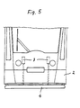
- the double provided as shown in FIG. 5 adjustment 7 each be designed as electro-mechanical spindle drive.
- the adjusting units 7 are preferably located behind the front wall 2 of the vehicle, possibly also in the driver's compartment.
- the front apron 4 When the vehicle, as shown in Fig. 1, is on flat rails or drives, takes the front apron 4 a middle position. In the sense of the wanted Cover of said gap-shaped opening 3, the front apron. 4 adjusted down when the vehicle is a dome of the rail system travels (see Fig. 2). On the other hand, as soon as the vehicle drives through a hollow, an adjustment of the front apron 4 is done upwards. In all these operating situations the gap-shaped opening 3 has a relatively low, largely constant Height (order of magnitude about 120 mm), so that in an accident no persons or larger objects get under the vehicle can.
- a sensor unit 8 is provided, the at least one measuring element having.
- the trained as a proximity sensor Sensor unit 8 between the car body 5 and one of the axis of rotation 6a remote frame part 6b of the chassis 6 is arranged.
- the recorded Sensor unit 8 the the course of the rail level 1 at dome or Muldenfahrt proportional pitching movements of the chassis 6 against the car body 5 and also height movements of the car body 5 due to the secondary suspension of the rail vehicle.
- the front apron 4 is corresponding in height adjusted.
- the specified in Fig. 4 position A of the frame part 6b corresponds to the operating situation of Figure 1 "level rail level 1".
- position B belongs to Fig. 2 "Kuppenfahrt" and position C to Fig. 3 "Muldenfahrt".
- the sensor unit 8 be placed in the vicinity of the front wall 2 of the car body 5 (not shown).
- the sensor unit 8 detects there the respective distance between the Car body 5 and the top edge of the rail level 1 directly, where the measured distance for lifting or lowering movements of the front apron 4 is implemented accordingly.
Landscapes
- Engineering & Computer Science (AREA)
- Life Sciences & Earth Sciences (AREA)
- Wood Science & Technology (AREA)
- Mechanical Engineering (AREA)
- Body Structure For Vehicles (AREA)
- Train Traffic Observation, Control, And Security (AREA)
- Refuge Islands, Traffic Blockers, Or Guard Fence (AREA)
- Control Of Vehicles With Linear Motors And Vehicles That Are Magnetically Levitated (AREA)
- Machines For Laying And Maintaining Railways (AREA)
Description
- Fig. 1
- den vorderen Bereich eines Schienenfahrzeuges auf ebenen Schienen, in Seitenansicht,
- Fig. 2
- das Fahrzeug nach Fig. 1 auf einer Kuppe der Schienenanlage,
- Fig. 3
- das Fahrzeug nach Fig. 1 in einer Mulde der Schienenanlage,
- Fig. 4
- die Einzelheit Z in Fig. 2 bzw. Fig. 3 in vergrößertem Maßstab,
- Fig. 5
- die Vorderansicht des Schienenfahrzeuges nach Fig. 1.
- 1
- Schienenniveau
- 2
- Frontwand
- 3
- spaltförmige Öffnung
- 4
- höhenverstellbare Bügschürze
- 5
- Wagenkasten
- 6
- Fahrwerk
- 6a
- Drehachse
- 6b
- Rahmenteil
- 7
- Verstelleinheit
- 8
- Sensoreinheit
Claims (5)
- Schienenfahrzeug, insbesondere Straßen- oder Stadtbahnwagen für den Nahverkehr, bei dem zwischen dem Schienenniveau (1) und der Unterkante der Frontwand (2) oder der Unterkante einer frontseitig befestigten Schürze eine spaltförmige Öffnung (3) besteht, wobei das Fahrzeug eine die spaltförmige Öffnung (3) abdeckende, in der Höhe schwenkbar angelenkte Bugschürze (4) aufweist, dadurch gekennzeichnet, dass die Bugschürze (4) durch zumindest eine Verstelleinheit (7) mit dem Fahrzeug verbunden und derart in ihrem Höhenmaß oberhalb des Schienenniveaus (1) einstellbar ist, dass die spaltförmige Öffnung (3) bei allen Betriebszuständen (Befahren von Ebenen, Mulden und Kuppen der Schienenanlage) eine relativ geringe, weitgehend konstante Höhenlage hat.
- Schienenfahrzeug nach Anspruch 2, dadurch gekennzeichnet, dass die Verstelleinheit (7) als elektro-mechanischer Stellantrieb ausgeführt ist.
- Schienenfahrzeug nach Anspruch 1 oder 2, dadurch gekennzeichnet, dass die Höheneinstellung der Bugschürze (4) über die Signale einer den Höhenverlauf des Schienenniveaus (1) sowie Höhenbewegungen des Wagenkastens (5) auf Grund der Sekundärfederung messende Sensoreinheit (8) erfolgt.
- Schienenfahrzeug nach Anspruch 3, dadurch gekennzeichnet, daß die Sensoreinheit (8) zwischen dem Wagenkasten (5) und einem von der Drehachse (6a) entfernten Rahmenteil (6b) des Fahrwerkes (6) angeordnet ist.
- Schienenfahrzeug nach Anspruch 3, dadurch gekennzeichnet, dass die Sensoreinheit (8) in der Nähe der Frontwand (2) des Wagenkastens (5) platziert ist.
Applications Claiming Priority (2)
| Application Number | Priority Date | Filing Date | Title |
|---|---|---|---|
| DE10005683 | 2000-02-09 | ||
| DE10005683A DE10005683A1 (de) | 2000-02-09 | 2000-02-09 | Schienenfahrzeug, insbesondere Straßen- oder Stadtbahnwagen für den Nahverkehr |
Publications (3)
| Publication Number | Publication Date |
|---|---|
| EP1123851A2 EP1123851A2 (de) | 2001-08-16 |
| EP1123851A3 EP1123851A3 (de) | 2003-08-20 |
| EP1123851B1 true EP1123851B1 (de) | 2005-01-12 |
Family
ID=7630321
Family Applications (1)
| Application Number | Title | Priority Date | Filing Date |
|---|---|---|---|
| EP01102460A Expired - Lifetime EP1123851B1 (de) | 2000-02-09 | 2001-02-03 | Schienenfahrzeug, insbesondere Strassen- oder Stadtbahnwagen für den Nahverkehr |
Country Status (4)
| Country | Link |
|---|---|
| EP (1) | EP1123851B1 (de) |
| AT (1) | ATE286820T1 (de) |
| DE (2) | DE10005683A1 (de) |
| ES (1) | ES2233505T3 (de) |
Cited By (2)
| Publication number | Priority date | Publication date | Assignee | Title |
|---|---|---|---|---|
| DE102013214424B3 (de) * | 2013-07-24 | 2014-11-20 | Siemens Aktiengesellschaft | Passiver Personeneinklemmschutz |
| CN111016971A (zh) * | 2019-12-03 | 2020-04-17 | 北京交通大学 | 高速铁路咽喉区列车通过间隔自动调整方法和装置 |
Families Citing this family (2)
| Publication number | Priority date | Publication date | Assignee | Title |
|---|---|---|---|---|
| ES2544603B1 (es) * | 2015-02-26 | 2016-06-08 | Miguel Ángel Martínez Fernández | Sistema antiatropello en vías férreas |
| DE102021109054B4 (de) | 2021-04-12 | 2025-07-17 | Bombardier Transportation Gmbh | Überfahrschutzvorrichtung und fahrzeug mit einer überfahrschutzvorrichtung |
Family Cites Families (7)
| Publication number | Priority date | Publication date | Assignee | Title |
|---|---|---|---|---|
| DE103266C (de) * | ||||
| DE214049C (de) * | ||||
| US1383196A (en) * | 1920-09-30 | 1921-06-28 | Carl O First | Car-fender |
| FR554005A (fr) * | 1921-11-07 | 1923-06-04 | Appareil protecteur pour tramways | |
| NL8900633A (nl) * | 1989-03-15 | 1990-10-01 | Sicommerce Ag | Beweegbare treinneus. |
| DE4216025A1 (de) * | 1992-05-15 | 1993-11-18 | Werner Schnaebele | Schutzvorrichtung an Fahrzeugen |
| DE9409208U1 (de) * | 1994-06-07 | 1995-07-06 | Duewag Ag, 47829 Krefeld | Abdeckung einer Mittelpufferkupplung für Schienenfahrzeuge |
-
2000
- 2000-02-09 DE DE10005683A patent/DE10005683A1/de not_active Withdrawn
-
2001
- 2001-02-03 EP EP01102460A patent/EP1123851B1/de not_active Expired - Lifetime
- 2001-02-03 AT AT01102460T patent/ATE286820T1/de active
- 2001-02-03 DE DE50105043T patent/DE50105043D1/de not_active Expired - Lifetime
- 2001-02-03 ES ES01102460T patent/ES2233505T3/es not_active Expired - Lifetime
Cited By (3)
| Publication number | Priority date | Publication date | Assignee | Title |
|---|---|---|---|---|
| DE102013214424B3 (de) * | 2013-07-24 | 2014-11-20 | Siemens Aktiengesellschaft | Passiver Personeneinklemmschutz |
| EP2829454A1 (de) | 2013-07-24 | 2015-01-28 | Siemens Aktiengesellschaft | Passiver Personeneinklemmschutz |
| CN111016971A (zh) * | 2019-12-03 | 2020-04-17 | 北京交通大学 | 高速铁路咽喉区列车通过间隔自动调整方法和装置 |
Also Published As
| Publication number | Publication date |
|---|---|
| ES2233505T3 (es) | 2005-06-16 |
| DE50105043D1 (de) | 2005-02-17 |
| EP1123851A2 (de) | 2001-08-16 |
| DE10005683A1 (de) | 2001-08-16 |
| ATE286820T1 (de) | 2005-01-15 |
| EP1123851A3 (de) | 2003-08-20 |
Similar Documents
| Publication | Publication Date | Title |
|---|---|---|
| DE19649280B4 (de) | Vorrichtung und Verfahren zum Leiten von Individuenströmen | |
| EP2019960A2 (de) | Messeinrichtung zur ermittlung des ist-zustands von radsätzen | |
| DE3935740C2 (de) | ||
| DE102013002096A1 (de) | Hochgeschwindigkeitszug mit geringem Energieumsatz | |
| DE2217975C3 (de) | An einem Fahrzeug, insbesondere Schienenfahrzeug, angeordnete Einrichtung zum Reinigen von Schotterbetten, Gleisschwellen u.dgl. einer Gleisanlage | |
| EP1123851B1 (de) | Schienenfahrzeug, insbesondere Strassen- oder Stadtbahnwagen für den Nahverkehr | |
| EP0290930B1 (de) | Bahnsystem zum Betrieb eines entgleisungssicheren Hochgeschwindigkeits-Schienenfahrzeuges | |
| EP0838386B1 (de) | Schienenfahrzeug mit mindenstens einem Fahrwerk und Fahrwerk für ein derartiges Fahrzeug | |
| DE2108663A1 (de) | Zweischienen-Hängebahn mit Linearmotor | |
| DE3424682C2 (de) | ||
| DE20002278U1 (de) | Schienenfahrzeug, insbesondere Straßen- oder Stadtbahnwagen für den Nahverkehr | |
| EP1171336B1 (de) | Schienenfahrzeug | |
| DE29723673U1 (de) | Zweirichtungsfahrbare Universal-Zugmaschine für die Schienenfahrt bei der modernen Eisenbahn sowie für die Befahrung von Straßen | |
| DE3023709A1 (de) | Standseilbahn | |
| DE8717556U1 (de) | Gelenkwagen für den Nahverkehr | |
| EP3081450A1 (de) | Transportfahrzeug | |
| DE3717003A1 (de) | Schienenfahrzeug, insbesondere stadtbahnwagen | |
| EP0190690A2 (de) | Kabinenbahn für den Personentransport | |
| DE922949C (de) | Befoerderungsmittel zum Befahren von spurlosen und spurgebundenen Bahnen sowie Anlage hierzu | |
| CH421723A (de) | Einstieganordnung für öffentliche Verkehrsmittel | |
| DE2632324C2 (de) | ||
| EP0066748B1 (de) | Schienenfahrzeug, insbesondere Stadtbahnwagen | |
| EP0742132B1 (de) | Vorrichtung zur Lagerung eines Aufbaus eines Eisenbahnwagens auf seinem Untergestell | |
| EP0633354A1 (de) | Personenbeförderungssystem | |
| EP3737598B1 (de) | Fahrzeugbrückenkasten und ein mehrgliedriges schienenfahrzeug |
Legal Events
| Date | Code | Title | Description |
|---|---|---|---|
| PUAI | Public reference made under article 153(3) epc to a published international application that has entered the european phase |
Free format text: ORIGINAL CODE: 0009012 |
|
| AK | Designated contracting states |
Kind code of ref document: A2 Designated state(s): AT BE CH CY DE DK ES FI FR GB GR IE IT LI LU MC NL PT SE TR |
|
| AX | Request for extension of the european patent |
Free format text: AL;LT;LV;MK;RO;SI |
|
| RAP1 | Party data changed (applicant data changed or rights of an application transferred) |
Owner name: SIEMENS AKTIENGESELLSCHAFT |
|
| PUAL | Search report despatched |
Free format text: ORIGINAL CODE: 0009013 |
|
| AK | Designated contracting states |
Designated state(s): AT BE CH CY DE DK ES FI FR GB GR IE IT LI LU MC NL PT SE TR |
|
| AX | Request for extension of the european patent |
Extension state: AL LT LV MK RO SI |
|
| RIC1 | Information provided on ipc code assigned before grant |
Ipc: 7B 61F 19/06 A Ipc: 7B 61D 17/06 B |
|
| 17P | Request for examination filed |
Effective date: 20030902 |
|
| 17Q | First examination report despatched |
Effective date: 20031110 |
|
| AKX | Designation fees paid |
Designated state(s): AT BE CH CY DE DK ES FI FR GB GR IE IT LI LU MC NL PT SE TR |
|
| GRAP | Despatch of communication of intention to grant a patent |
Free format text: ORIGINAL CODE: EPIDOSNIGR1 |
|
| GRAS | Grant fee paid |
Free format text: ORIGINAL CODE: EPIDOSNIGR3 |
|
| GRAA | (expected) grant |
Free format text: ORIGINAL CODE: 0009210 |
|
| AK | Designated contracting states |
Kind code of ref document: B1 Designated state(s): AT BE CH CY DE DK ES FI FR GB GR IE IT LI LU MC NL PT SE TR |
|
| PG25 | Lapsed in a contracting state [announced via postgrant information from national office to epo] |
Ref country code: FI Free format text: LAPSE BECAUSE OF FAILURE TO SUBMIT A TRANSLATION OF THE DESCRIPTION OR TO PAY THE FEE WITHIN THE PRESCRIBED TIME-LIMIT Effective date: 20050112 Ref country code: IE Free format text: LAPSE BECAUSE OF FAILURE TO SUBMIT A TRANSLATION OF THE DESCRIPTION OR TO PAY THE FEE WITHIN THE PRESCRIBED TIME-LIMIT Effective date: 20050112 Ref country code: TR Free format text: LAPSE BECAUSE OF FAILURE TO SUBMIT A TRANSLATION OF THE DESCRIPTION OR TO PAY THE FEE WITHIN THE PRESCRIBED TIME-LIMIT Effective date: 20050112 |
|
| REG | Reference to a national code |
Ref country code: GB Ref legal event code: FG4D Free format text: NOT ENGLISH |
|
| REG | Reference to a national code |
Ref country code: CH Ref legal event code: EP Ref country code: CH Ref legal event code: NV Representative=s name: SIEMENS SCHWEIZ AG |
|
| PG25 | Lapsed in a contracting state [announced via postgrant information from national office to epo] |
Ref country code: LU Free format text: LAPSE BECAUSE OF NON-PAYMENT OF DUE FEES Effective date: 20050203 Ref country code: CY Free format text: LAPSE BECAUSE OF FAILURE TO SUBMIT A TRANSLATION OF THE DESCRIPTION OR TO PAY THE FEE WITHIN THE PRESCRIBED TIME-LIMIT Effective date: 20050203 |
|
| REF | Corresponds to: |
Ref document number: 50105043 Country of ref document: DE Date of ref document: 20050217 Kind code of ref document: P |
|
| REG | Reference to a national code |
Ref country code: IE Ref legal event code: FG4D Free format text: GERMAN |
|
| PG25 | Lapsed in a contracting state [announced via postgrant information from national office to epo] |
Ref country code: MC Free format text: LAPSE BECAUSE OF NON-PAYMENT OF DUE FEES Effective date: 20050228 |
|
| GBT | Gb: translation of ep patent filed (gb section 77(6)(a)/1977) |
Effective date: 20050222 |
|
| PG25 | Lapsed in a contracting state [announced via postgrant information from national office to epo] |
Ref country code: SE Free format text: LAPSE BECAUSE OF FAILURE TO SUBMIT A TRANSLATION OF THE DESCRIPTION OR TO PAY THE FEE WITHIN THE PRESCRIBED TIME-LIMIT Effective date: 20050412 Ref country code: DK Free format text: LAPSE BECAUSE OF FAILURE TO SUBMIT A TRANSLATION OF THE DESCRIPTION OR TO PAY THE FEE WITHIN THE PRESCRIBED TIME-LIMIT Effective date: 20050412 |
|
| REG | Reference to a national code |
Ref country code: ES Ref legal event code: FG2A Ref document number: 2233505 Country of ref document: ES Kind code of ref document: T3 |
|
| REG | Reference to a national code |
Ref country code: IE Ref legal event code: FD4D |
|
| PLBE | No opposition filed within time limit |
Free format text: ORIGINAL CODE: 0009261 |
|
| STAA | Information on the status of an ep patent application or granted ep patent |
Free format text: STATUS: NO OPPOSITION FILED WITHIN TIME LIMIT |
|
| ET | Fr: translation filed | ||
| 26N | No opposition filed |
Effective date: 20051013 |
|
| PG25 | Lapsed in a contracting state [announced via postgrant information from national office to epo] |
Ref country code: PT Free format text: LAPSE BECAUSE OF NON-PAYMENT OF DUE FEES Effective date: 20050612 |
|
| PG25 | Lapsed in a contracting state [announced via postgrant information from national office to epo] |
Ref country code: GR Free format text: LAPSE BECAUSE OF NON-PAYMENT OF DUE FEES Effective date: 20050112 |
|
| REG | Reference to a national code |
Ref country code: CH Ref legal event code: PCAR Free format text: SIEMENS SCHWEIZ AG;INTELLECTUAL PROPERTY FREILAGERSTRASSE 40;8047 ZUERICH (CH) |
|
| PGFP | Annual fee paid to national office [announced via postgrant information from national office to epo] |
Ref country code: ES Payment date: 20100304 Year of fee payment: 10 |
|
| PGFP | Annual fee paid to national office [announced via postgrant information from national office to epo] |
Ref country code: BE Payment date: 20100217 Year of fee payment: 10 |
|
| PGFP | Annual fee paid to national office [announced via postgrant information from national office to epo] |
Ref country code: NL Payment date: 20100203 Year of fee payment: 10 |
|
| PG25 | Lapsed in a contracting state [announced via postgrant information from national office to epo] |
Ref country code: IT Free format text: LAPSE BECAUSE OF NON-PAYMENT OF DUE FEES Effective date: 20100203 |
|
| BERE | Be: lapsed |
Owner name: *SIEMENS A.G. Effective date: 20110228 |
|
| REG | Reference to a national code |
Ref country code: NL Ref legal event code: V1 Effective date: 20110901 |
|
| PG25 | Lapsed in a contracting state [announced via postgrant information from national office to epo] |
Ref country code: BE Free format text: LAPSE BECAUSE OF NON-PAYMENT OF DUE FEES Effective date: 20110228 |
|
| PG25 | Lapsed in a contracting state [announced via postgrant information from national office to epo] |
Ref country code: NL Free format text: LAPSE BECAUSE OF NON-PAYMENT OF DUE FEES Effective date: 20110901 |
|
| PG25 | Lapsed in a contracting state [announced via postgrant information from national office to epo] |
Ref country code: IT Free format text: LAPSE BECAUSE OF NON-PAYMENT OF DUE FEES Effective date: 20110203 |
|
| PGFP | Annual fee paid to national office [announced via postgrant information from national office to epo] |
Ref country code: IT Payment date: 20100224 Year of fee payment: 10 |
|
| REG | Reference to a national code |
Ref country code: ES Ref legal event code: FD2A Effective date: 20130610 |
|
| PG25 | Lapsed in a contracting state [announced via postgrant information from national office to epo] |
Ref country code: ES Free format text: LAPSE BECAUSE OF NON-PAYMENT OF DUE FEES Effective date: 20110204 |
|
| PGFP | Annual fee paid to national office [announced via postgrant information from national office to epo] |
Ref country code: FR Payment date: 20140212 Year of fee payment: 14 Ref country code: AT Payment date: 20140109 Year of fee payment: 14 |
|
| PGFP | Annual fee paid to national office [announced via postgrant information from national office to epo] |
Ref country code: GB Payment date: 20140210 Year of fee payment: 14 |
|
| REG | Reference to a national code |
Ref country code: AT Ref legal event code: MM01 Ref document number: 286820 Country of ref document: AT Kind code of ref document: T Effective date: 20150203 |
|
| GBPC | Gb: european patent ceased through non-payment of renewal fee |
Effective date: 20150203 |
|
| REG | Reference to a national code |
Ref country code: FR Ref legal event code: ST Effective date: 20151030 |
|
| PG25 | Lapsed in a contracting state [announced via postgrant information from national office to epo] |
Ref country code: AT Free format text: LAPSE BECAUSE OF NON-PAYMENT OF DUE FEES Effective date: 20150203 |
|
| PG25 | Lapsed in a contracting state [announced via postgrant information from national office to epo] |
Ref country code: GB Free format text: LAPSE BECAUSE OF NON-PAYMENT OF DUE FEES Effective date: 20150203 |
|
| PG25 | Lapsed in a contracting state [announced via postgrant information from national office to epo] |
Ref country code: FR Free format text: LAPSE BECAUSE OF NON-PAYMENT OF DUE FEES Effective date: 20150302 |
|
| PGFP | Annual fee paid to national office [announced via postgrant information from national office to epo] |
Ref country code: DE Payment date: 20170419 Year of fee payment: 17 |
|
| REG | Reference to a national code |
Ref country code: CH Ref legal event code: PCOW Free format text: NEW ADDRESS: WERNER-VON-SIEMENS-STRASSE 1, 80333 MUENCHEN (DE) |
|
| PGFP | Annual fee paid to national office [announced via postgrant information from national office to epo] |
Ref country code: CH Payment date: 20180516 Year of fee payment: 18 |
|
| REG | Reference to a national code |
Ref country code: DE Ref legal event code: R119 Ref document number: 50105043 Country of ref document: DE |
|
| PG25 | Lapsed in a contracting state [announced via postgrant information from national office to epo] |
Ref country code: DE Free format text: LAPSE BECAUSE OF NON-PAYMENT OF DUE FEES Effective date: 20180901 |
|
| REG | Reference to a national code |
Ref country code: CH Ref legal event code: PUE Owner name: SIEMENS MOBILITY GMBH, DE Free format text: FORMER OWNER: SIEMENS AKTIENGESELLSCHAFT, DE |
|
| REG | Reference to a national code |
Ref country code: CH Ref legal event code: PL |
|
| PG25 | Lapsed in a contracting state [announced via postgrant information from national office to epo] |
Ref country code: CH Free format text: LAPSE BECAUSE OF NON-PAYMENT OF DUE FEES Effective date: 20190228 Ref country code: LI Free format text: LAPSE BECAUSE OF NON-PAYMENT OF DUE FEES Effective date: 20190228 |