EP1112811A2 - Bandschleifmaschine zum Schleifen von Rohren - Google Patents
Bandschleifmaschine zum Schleifen von Rohren Download PDFInfo
- Publication number
- EP1112811A2 EP1112811A2 EP00811127A EP00811127A EP1112811A2 EP 1112811 A2 EP1112811 A2 EP 1112811A2 EP 00811127 A EP00811127 A EP 00811127A EP 00811127 A EP00811127 A EP 00811127A EP 1112811 A2 EP1112811 A2 EP 1112811A2
- Authority
- EP
- European Patent Office
- Prior art keywords
- arm
- belt
- spring
- grinding
- grinding machine
- Prior art date
- Legal status (The legal status is an assumption and is not a legal conclusion. Google has not performed a legal analysis and makes no representation as to the accuracy of the status listed.)
- Granted
Links
Images

Classifications
-
- B—PERFORMING OPERATIONS; TRANSPORTING
- B24—GRINDING; POLISHING
- B24B—MACHINES, DEVICES, OR PROCESSES FOR GRINDING OR POLISHING; DRESSING OR CONDITIONING OF ABRADING SURFACES; FEEDING OF GRINDING, POLISHING, OR LAPPING AGENTS
- B24B5/00—Machines or devices designed for grinding surfaces of revolution on work, including those which also grind adjacent plane surfaces; Accessories therefor
- B24B5/02—Machines or devices designed for grinding surfaces of revolution on work, including those which also grind adjacent plane surfaces; Accessories therefor involving centres or chucks for holding work
- B24B5/04—Machines or devices designed for grinding surfaces of revolution on work, including those which also grind adjacent plane surfaces; Accessories therefor involving centres or chucks for holding work for grinding cylindrical surfaces externally
-
- B—PERFORMING OPERATIONS; TRANSPORTING
- B24—GRINDING; POLISHING
- B24B—MACHINES, DEVICES, OR PROCESSES FOR GRINDING OR POLISHING; DRESSING OR CONDITIONING OF ABRADING SURFACES; FEEDING OF GRINDING, POLISHING, OR LAPPING AGENTS
- B24B21/00—Machines or devices using grinding or polishing belts; Accessories therefor
- B24B21/18—Accessories
- B24B21/20—Accessories for controlling or adjusting the tracking or the tension of the grinding belt
-
- B—PERFORMING OPERATIONS; TRANSPORTING
- B24—GRINDING; POLISHING
- B24B—MACHINES, DEVICES, OR PROCESSES FOR GRINDING OR POLISHING; DRESSING OR CONDITIONING OF ABRADING SURFACES; FEEDING OF GRINDING, POLISHING, OR LAPPING AGENTS
- B24B23/00—Portable grinding machines, e.g. hand-guided; Accessories therefor
- B24B23/06—Portable grinding machines, e.g. hand-guided; Accessories therefor with abrasive belts, e.g. with endless travelling belts; Accessories therefor
Definitions
- the invention relates to a belt grinding machine for Grinding pipes according to the generic term of Claim 1.
- a pipe grinder is also known, which with a sanding belt that works by an output roller on Drive motor driven two spaced from this arranged roles revolving, which roles at the ends two relative to the axis of rotation of the driven roller leg pivotable to each other.
- To edit a pipe becomes the latter against the strand of the Sanding belt between the two relative to each other movable rollers and thereby partially entwined.
- One the two Spreading spring holds the sanding belt to everyone Time excited.
- the disadvantage of this device is that with increasing Wrap angle of the sanding belt around that too machining pipe increasing spring force, which in turn only by a corresponding increase in the contact pressure of the Band on the pipe to be processed can be overcome.
- the tube is one-sided with a higher Contact pressure is applied by the grinding belt and thereby this in turn causes an uneven grinding pattern.
- the high contact forces which are necessary for the great wrapping on the other hand a correspondingly high resistance on Sanding belt, and as a result, increased engine power necessary for the drive, which leads to an increase in Total weight of the grinding machine leads.
- the object of the present invention is to create a Belt grinder, with little effort a loop of about 180 degrees of angle of a pipe is possible without a significantly increased Drive power is required.
- the drive unit 3 for example an electric motor or a pneumatic motor, is shown as a rectangle on the right-hand side.
- the corresponding energy (electricity or air) is supplied through the feed line 5.
- the drive unit 3 can be switched on and off with a switch 7.
- two swivel arms 11 and 13 are fastened to the drive unit 3, at least one of which is pivotably mounted about the axis of rotation A in the vicinity of the output roller 9.
- a handle 15 is also attached, on which the operator holds the machine 1 with the second hand.
- the swivel arm 13 is pushed away from the fixed arm 11 by a spreading spring 17 (arrow P).
- deflection wheels 19, 21 are placed, which carry an endless grinding belt 23 that runs around these two deflection wheels 19, 21 and the driven roller 9.
- the known grinding machine is during of the grinding process, i.e. between the two Deflection wheels 19, 21 loop around the grinding belt 23 tubular workpiece 25 at an angle beta of less than 180 °.
- the run 26 of the Sanding belt 23 tangentially from the deflection wheel 19 to the deflection wheel 21.
- the wrap angle beta the two Deflection wheels 19,21 against the force of the spring 17th brought together.
- the wrap angle on the workpiece 25 is determined by the force F with which the Operator the belt sander 1 against that Workpiece 25 presses, determined.
- This handle 15 sits at the end of one bracket 31 attached at an angle to the swivel arm 13 there is also a toggle lever 33 on the swivel arm 13 attached or formed, at the end of the spring 17th attacks.
- the second end of the spring 17 is at the second fixed arm 27 attached.
- the Toggle arm 33 substantially perpendicular to the axis F the spring 17.
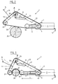
- the first fixed, the deflection wheel 19th load-bearing arm 11 can have a fixed length or how shown in the example according to Figures 2 and 3, as Telescopic arm so that its length L, i.e. the distance of the axis of rotation of the roller 19 to the axis of rotation A of Output roller 9 and thus also the distance to the deflection roller 21 for the purpose of adaptation to the diameter D of the workpiece 25 is changeable.
- the shortening takes place by actively pivoting the swivel arm 13 with one hand of the operator counterclockwise about the axis of rotation of the deflection wheel 29.
- the deflection wheel 21 consequently approaches the deflection wheel 19 on one circular arc-shaped path that is only marginally from a Straight line deviates.
- With increasing swivel angle of the Swivel arm 13 increases the angle between the Axis of the spring 17 and the toggle arm 33. This leads to a continuous decrease in the force of the spring 17 the swivel arm 13.
- the arrangement of the handle 15 on the pivotable arm 13 and also at the end of the boom 31 allows the Pivotal movement of the arm 13 not only by the Relative movement of workpiece 25 to machine 1 trigger, but actively by pivoting the arm 13 to support with the boom 31.
Landscapes
- Engineering & Computer Science (AREA)
- Mechanical Engineering (AREA)
- Finish Polishing, Edge Sharpening, And Grinding By Specific Grinding Devices (AREA)
- Polishing Bodies And Polishing Tools (AREA)
Abstract
Description
- Figur 1
- eine schematische Darstellung der bekannten Bandschleifmaschine mit zwei v-förmig angeordneten relativ zueinander verschwenkbaren Schwenkarmen,
- Figur 2
- eine Seitenansicht der erfindungsgemässen Schleifmaschine ausser Eingriff mit dem Werkstück und
- Figur 3
- eine Seitenansicht der erfindungsgemässen Schleifmaschine in Eingriff mit dem Werkstück.
Am stirnseitigen Ende des Antriebsaggregates 3 sitzt eine Abtriebsrolle 9. Im weiteren sind am Antriebsaggregat 3 zwei Schwenkarme 11 und 13 befestigt, von denen mindestens einer um die Drehachse A in der Nähe der Abtriebsrolle 9 schwenkbar gelagert ist. Am fest mit dem Antriebsaggregat 3 verbundenen Arm 11 ist weiter ein Handgriff 15 befestigt, an dem die Bedienungsperson die Maschine 1 mit der zweiten Hand festhält. Der Schwenkarm 13 wird durch eine spreizend wirkende Feder 17 vom feststehenden Arm 11 weggedrückt (Pfeil P). An den Enden der beiden Arme 11,13 sind Umlenkräder 19,21 aufgesetzt, welche ein um diese beiden Umlenkräder 19,21 und die Abtriebsrolle 9 umlaufendes endloses Schleifband 23 tragen.
Claims (6)
- Bandschleifmaschine (1) zum Schleifen von Rohren (25), umfassend ein Antriebsaggregat (3) mit einer Abtriebsrolle (9) zum Antrieb eines endlos umzulaufen bestimmten Schleifbandes (23), zwei Umlenkräder (19,21) von denen das eine am Ende eines federbelasteten Schwenkarms (13) und das andere am Ende eines ersten, fest mit dem Antriebsaggregat (3) verbundenen Armes (11) angeordnet ist und eine Feder (17) zum Spannen des Schleifbandes (23) durch Schwenken des Schwenkarmes (13), dadurch gekennzeichnet, dass der schwenkbare Arm (13) um die Drehachse (A) einer zusätzlichen Umlenkrolle (29) auf dem Ende eines zweiten, mit dem Antriebsaggregat (3) fest verbundenen Armes (27) schwenkbar ist und dass die Feder (17) zwischen dem zweiten Arm (27) und dem schwenkbaren Arm (13) eingesetzt ist.
- Bandschleifmaschine nach Anspruch 1, dadurch gekennzeichnet, dass die Feder (17) an einem mit dem schwenkbaren Arm (13) fest verbundenen Kniehebelarm (33) angreift.
- Bandschleifmaschine nach Anspruch 2, dadurch gekennzeichnet, dass der Kniehebelarm (33) vor dem Kontakt des Schleifbandes (23) mit dem Werkstück (25) rechtwinklig zur Federachse liegt und mit zunehmender Umschlingung des Werkstücks (25) durch das Schleifband (23) der Umschlingungswinkel (beta) zunimmt und die Kraft der Feder (17) abnimmt.
- Bandschleifmaschine nach einem der Ansprüche 1 bis 3, dadurch gekennzeichnet, dass die Länge (L) des ersten Armes (11) verstellbar ist.
- Bandschleifmaschine nach einem der Ansprüche 1 bis 4, dadurch gekennzeichnet, dass am schwenkbaren Arm (13) ein Führungshebel (31) befestigt ist, an dessen Ende ein Handgriff (15) sitzt.
- Bandschleifmaschine nach Anspruch 5, dadurch gekennzeichnet, dass der Führungshebel (31) mit dem Handgriff (15) zum aktiven Schwenken des schwenkbaren Arms (13) ausgebildet ist.
Applications Claiming Priority (2)
| Application Number | Priority Date | Filing Date | Title |
|---|---|---|---|
| CH42000 | 2000-01-03 | ||
| CH42000 | 2000-01-03 |
Publications (3)
| Publication Number | Publication Date |
|---|---|
| EP1112811A2 true EP1112811A2 (de) | 2001-07-04 |
| EP1112811A3 EP1112811A3 (de) | 2003-10-29 |
| EP1112811B1 EP1112811B1 (de) | 2005-04-27 |
Family
ID=4186608
Family Applications (1)
| Application Number | Title | Priority Date | Filing Date |
|---|---|---|---|
| EP00811127A Expired - Lifetime EP1112811B1 (de) | 2000-01-03 | 2000-11-27 | Bandschleifmaschine zum Schleifen von Rohren |
Country Status (3)
| Country | Link |
|---|---|
| EP (1) | EP1112811B1 (de) |
| AT (1) | ATE294047T1 (de) |
| DE (1) | DE50010157D1 (de) |
Cited By (26)
| Publication number | Priority date | Publication date | Assignee | Title |
|---|---|---|---|---|
| EP1647362A1 (de) | 2004-10-13 | 2006-04-19 | C. & E. Fein GmbH | Bandschleifmaschine |
| DE102004050528A1 (de) * | 2004-10-16 | 2006-04-20 | Harald Zahn Gmbh | Bandschleifgerät |
| WO2008084265A1 (en) * | 2007-01-12 | 2008-07-17 | Renko Brkanovic | Articulated device for grinding and polishing of round objects |
| WO2009049868A1 (de) * | 2007-10-16 | 2009-04-23 | Nagel Maschinen- Und Werkzeugfabrik Gmbh | Andrückeinrichtung für schneidmittel sowie vorrichtung und verfahren zur finishbearbeitung von umfangsflächen an zylindrischen werkstückabschnitten |
| DE102011104010A1 (de) | 2011-06-10 | 2012-12-13 | Gerd Eisenblätter Gmbh | Bandschleifvorrichtung |
| CN103506922A (zh) * | 2013-08-01 | 2014-01-15 | 浙江精一重工有限公司 | 一种轴类零件非规则外圆面自动抛光方法 |
| CN106737074A (zh) * | 2016-11-28 | 2017-05-31 | 南安市达腾商务服务有限公司 | 一种具有弹性装置的建材钢管除锈设备 |
| CN106926094A (zh) * | 2017-04-06 | 2017-07-07 | 宁波辛迪自动化科技有限公司 | 一种砂带机装置 |
| CN108527086A (zh) * | 2018-07-03 | 2018-09-14 | 东莞理工学院 | 一种喷砂式回转体密封槽抛光机 |
| CN109202737A (zh) * | 2018-11-14 | 2019-01-15 | 邢箫 | 一种不锈钢焊管的焊缝打磨工艺 |
| DE102017008394A1 (de) * | 2017-09-07 | 2019-03-07 | Lubas Maschinen Gmbh | Schleifen von Scheibenmessern |
| CN109500667A (zh) * | 2019-01-16 | 2019-03-22 | 邢箫 | 一种细长金属管件连续打磨设备 |
| CN109514361A (zh) * | 2018-11-14 | 2019-03-26 | 邢箫 | 一种不锈钢管的焊缝打磨设备 |
| CN109531301A (zh) * | 2019-01-16 | 2019-03-29 | 邢箫 | 一种细长金属管件打磨工艺 |
| CN109773632A (zh) * | 2019-04-01 | 2019-05-21 | 无锡锡钻地质装备有限公司 | 一种地质勘探钻杆加工设备 |
| CN110587394A (zh) * | 2019-09-24 | 2019-12-20 | 哈尔滨斯特莱茵环境科技有限公司 | 一种玻璃钢膜壳的表面打磨系统 |
| CN111015455A (zh) * | 2019-12-29 | 2020-04-17 | 合肥宽信机电有限公司 | 一种车桥铸造配件表面打磨装置 |
| CN111761479A (zh) * | 2019-03-31 | 2020-10-13 | 华北水利水电大学 | 圆柱形工件抛光机 |
| CN112518443A (zh) * | 2020-11-30 | 2021-03-19 | 山东艾泰克环保科技股份有限公司 | 一种储气筒加工用打磨装置 |
| CN112605812A (zh) * | 2020-12-18 | 2021-04-06 | 北京邮电大学 | 摆动式弯管抛光拉丝机 |
| CN113370039A (zh) * | 2021-08-11 | 2021-09-10 | 新沂市鹏立机械有限公司 | 一种缝纫机机头加工打磨装置 |
| CN114871914A (zh) * | 2022-05-17 | 2022-08-09 | 浙江金马逊机械有限公司 | 一种用于航空航天管件的自适应打磨方法及装置 |
| CN115056098A (zh) * | 2022-07-05 | 2022-09-16 | 安徽康宏精密制造有限公司 | 一种用于小型五金配件抛光设备及方法 |
| CN115365961A (zh) * | 2022-09-16 | 2022-11-22 | 福建达宇重型数控机床有限公司 | 一种数控轧辊磨床砂带磨削装置及其使用方法 |
| CN115922511A (zh) * | 2023-01-07 | 2023-04-07 | 山东省三鼎汽车配件有限公司 | 一种刹车盘粗磨装置 |
| CN116423346A (zh) * | 2023-05-08 | 2023-07-14 | 台升实业有限公司 | 一种实木加工用打磨修边设备及其打磨修边工艺 |
Families Citing this family (5)
| Publication number | Priority date | Publication date | Assignee | Title |
|---|---|---|---|---|
| DE202011002462U1 (de) | 2011-02-07 | 2011-04-28 | Metabowerke Gmbh | Rohrbandschleifeinheit |
| DE102011117412A1 (de) * | 2011-11-02 | 2013-05-02 | Holzer Gmbh | Rohrbandschleifvorrichtung |
| DE102012219638B4 (de) | 2012-10-26 | 2014-09-11 | Metabowerke Gmbh | Rohrbandschleifeinheit |
| CN108296946A (zh) * | 2018-03-19 | 2018-07-20 | 广东恒合信管业科技有限公司 | 一种用于管类的砂带打磨机 |
| WO2023106905A1 (en) * | 2022-02-07 | 2023-06-15 | Ozinskis Olegs | A machining device |
Citations (4)
| Publication number | Priority date | Publication date | Assignee | Title |
|---|---|---|---|---|
| US2560102A (en) * | 1946-10-24 | 1951-07-10 | Guinn J Edwin | Sander |
| US3049841A (en) * | 1959-07-13 | 1962-08-21 | Amos E Jackson | Portable sanders |
| US3566549A (en) * | 1969-01-21 | 1971-03-02 | James A Britton | Flexible all purpose drill attachment |
| US4603510A (en) * | 1984-08-27 | 1986-08-05 | Rasmussen Aaron P | Multiple position belt grinder |
-
2000
- 2000-11-27 DE DE50010157T patent/DE50010157D1/de not_active Expired - Lifetime
- 2000-11-27 AT AT00811127T patent/ATE294047T1/de active
- 2000-11-27 EP EP00811127A patent/EP1112811B1/de not_active Expired - Lifetime
Patent Citations (4)
| Publication number | Priority date | Publication date | Assignee | Title |
|---|---|---|---|---|
| US2560102A (en) * | 1946-10-24 | 1951-07-10 | Guinn J Edwin | Sander |
| US3049841A (en) * | 1959-07-13 | 1962-08-21 | Amos E Jackson | Portable sanders |
| US3566549A (en) * | 1969-01-21 | 1971-03-02 | James A Britton | Flexible all purpose drill attachment |
| US4603510A (en) * | 1984-08-27 | 1986-08-05 | Rasmussen Aaron P | Multiple position belt grinder |
Cited By (41)
| Publication number | Priority date | Publication date | Assignee | Title |
|---|---|---|---|---|
| EP1647362A1 (de) | 2004-10-13 | 2006-04-19 | C. & E. Fein GmbH | Bandschleifmaschine |
| DE102004050528A1 (de) * | 2004-10-16 | 2006-04-20 | Harald Zahn Gmbh | Bandschleifgerät |
| DE102004050528B4 (de) * | 2004-10-16 | 2008-08-21 | Harald Zahn Gmbh | Bandschleifgerät |
| WO2008084265A1 (en) * | 2007-01-12 | 2008-07-17 | Renko Brkanovic | Articulated device for grinding and polishing of round objects |
| US8517804B2 (en) | 2007-10-16 | 2013-08-27 | Nagel Maschinen- Und Werkzeugfabrik Gmbh | Pressing device for cutting means and apparatus and method for finishing circumferential surfaces on cylindrical parts of a workpiece |
| WO2009049868A1 (de) * | 2007-10-16 | 2009-04-23 | Nagel Maschinen- Und Werkzeugfabrik Gmbh | Andrückeinrichtung für schneidmittel sowie vorrichtung und verfahren zur finishbearbeitung von umfangsflächen an zylindrischen werkstückabschnitten |
| DE102007051047B4 (de) | 2007-10-16 | 2023-03-23 | Nagel Maschinen- Und Werkzeugfabrik Gmbh | Andrückeinrichtung für Finishband sowie Vorrichtung und Verfahren zur Finishbearbeitung von Umfangsflächen an zylindrischen Werkstückabschnitten |
| DE102011104010A1 (de) | 2011-06-10 | 2012-12-13 | Gerd Eisenblätter Gmbh | Bandschleifvorrichtung |
| CN103506922A (zh) * | 2013-08-01 | 2014-01-15 | 浙江精一重工有限公司 | 一种轴类零件非规则外圆面自动抛光方法 |
| CN103506922B (zh) * | 2013-08-01 | 2016-12-28 | 浙江精一重工有限公司 | 一种轴类零件非规则外圆面自动抛光方法 |
| CN106737074A (zh) * | 2016-11-28 | 2017-05-31 | 南安市达腾商务服务有限公司 | 一种具有弹性装置的建材钢管除锈设备 |
| CN106926094A (zh) * | 2017-04-06 | 2017-07-07 | 宁波辛迪自动化科技有限公司 | 一种砂带机装置 |
| DE102017008394A1 (de) * | 2017-09-07 | 2019-03-07 | Lubas Maschinen Gmbh | Schleifen von Scheibenmessern |
| CN108527086A (zh) * | 2018-07-03 | 2018-09-14 | 东莞理工学院 | 一种喷砂式回转体密封槽抛光机 |
| CN109514361B (zh) * | 2018-11-14 | 2020-05-12 | 佛山市康海钢制品有限公司 | 一种不锈钢管的焊缝打磨设备 |
| CN109514361A (zh) * | 2018-11-14 | 2019-03-26 | 邢箫 | 一种不锈钢管的焊缝打磨设备 |
| CN109202737A (zh) * | 2018-11-14 | 2019-01-15 | 邢箫 | 一种不锈钢焊管的焊缝打磨工艺 |
| CN109531301A (zh) * | 2019-01-16 | 2019-03-29 | 邢箫 | 一种细长金属管件打磨工艺 |
| CN109500667A (zh) * | 2019-01-16 | 2019-03-22 | 邢箫 | 一种细长金属管件连续打磨设备 |
| CN109500667B (zh) * | 2019-01-16 | 2021-06-25 | 安徽森米诺农业科技有限公司 | 一种细长金属管件连续打磨设备 |
| CN109531301B (zh) * | 2019-01-16 | 2021-08-24 | 佛山市顺德区雷公家和金属制品有限公司 | 一种细长金属管件打磨工艺 |
| CN111761479A (zh) * | 2019-03-31 | 2020-10-13 | 华北水利水电大学 | 圆柱形工件抛光机 |
| CN111761479B (zh) * | 2019-03-31 | 2024-05-17 | 华北水利水电大学 | 圆柱形工件抛光机 |
| CN109773632A (zh) * | 2019-04-01 | 2019-05-21 | 无锡锡钻地质装备有限公司 | 一种地质勘探钻杆加工设备 |
| CN109773632B (zh) * | 2019-04-01 | 2024-04-30 | 无锡锡钻地质装备有限公司 | 一种地质勘探钻杆加工设备 |
| CN110587394A (zh) * | 2019-09-24 | 2019-12-20 | 哈尔滨斯特莱茵环境科技有限公司 | 一种玻璃钢膜壳的表面打磨系统 |
| CN110587394B (zh) * | 2019-09-24 | 2024-04-16 | 哈尔滨斯特莱茵环境科技有限公司 | 一种玻璃钢膜壳的表面打磨系统 |
| CN111015455A (zh) * | 2019-12-29 | 2020-04-17 | 合肥宽信机电有限公司 | 一种车桥铸造配件表面打磨装置 |
| CN111015455B (zh) * | 2019-12-29 | 2021-05-25 | 合肥宽信机电有限公司 | 一种车桥铸造配件表面打磨装置 |
| CN112518443A (zh) * | 2020-11-30 | 2021-03-19 | 山东艾泰克环保科技股份有限公司 | 一种储气筒加工用打磨装置 |
| CN112605812A (zh) * | 2020-12-18 | 2021-04-06 | 北京邮电大学 | 摆动式弯管抛光拉丝机 |
| CN113370039A (zh) * | 2021-08-11 | 2021-09-10 | 新沂市鹏立机械有限公司 | 一种缝纫机机头加工打磨装置 |
| CN113370039B (zh) * | 2021-08-11 | 2021-10-26 | 新沂市鹏立机械有限公司 | 一种缝纫机机头加工打磨装置 |
| CN114871914A (zh) * | 2022-05-17 | 2022-08-09 | 浙江金马逊机械有限公司 | 一种用于航空航天管件的自适应打磨方法及装置 |
| CN115056098B (zh) * | 2022-07-05 | 2023-12-08 | 安徽康宏精密制造有限公司 | 一种用于小型五金配件抛光设备及方法 |
| CN115056098A (zh) * | 2022-07-05 | 2022-09-16 | 安徽康宏精密制造有限公司 | 一种用于小型五金配件抛光设备及方法 |
| CN115365961A (zh) * | 2022-09-16 | 2022-11-22 | 福建达宇重型数控机床有限公司 | 一种数控轧辊磨床砂带磨削装置及其使用方法 |
| CN115365961B (zh) * | 2022-09-16 | 2023-09-15 | 福建达宇重型数控机床有限公司 | 一种数控轧辊磨床砂带磨削装置及其使用方法 |
| CN115922511A (zh) * | 2023-01-07 | 2023-04-07 | 山东省三鼎汽车配件有限公司 | 一种刹车盘粗磨装置 |
| CN116423346A (zh) * | 2023-05-08 | 2023-07-14 | 台升实业有限公司 | 一种实木加工用打磨修边设备及其打磨修边工艺 |
| CN116423346B (zh) * | 2023-05-08 | 2023-11-24 | 台升实业有限公司 | 一种实木加工用打磨修边设备及其打磨修边工艺 |
Also Published As
| Publication number | Publication date |
|---|---|
| EP1112811A3 (de) | 2003-10-29 |
| DE50010157D1 (de) | 2005-06-02 |
| ATE294047T1 (de) | 2005-05-15 |
| EP1112811B1 (de) | 2005-04-27 |
Similar Documents
| Publication | Publication Date | Title |
|---|---|---|
| EP1112811B1 (de) | Bandschleifmaschine zum Schleifen von Rohren | |
| EP2673115B1 (de) | Rohrbandschleifeinheit | |
| EP0623421B1 (de) | Vorrichtung zum endseitigen Ausformen von rohrförmigen Werkstücken mit unterschiedlichen Durchmessern | |
| DE2705029A1 (de) | Verfahren und vorrichtung zum durchschneiden eines langgestreckten werkstueckes | |
| EP2047948A2 (de) | Vorrichtung zum Schleifen von Werkstücken | |
| DE102012219638B4 (de) | Rohrbandschleifeinheit | |
| DE2519190B2 (de) | Kopierschleifgerät zum maßgerechten Schleifen von Schaufelblättern für Turbinen und Verdichter | |
| CH649491A5 (de) | Vorrichtung zum abrichten und nachstellen einer schleifscheibe an einer zahnflanken-schleifmaschine. | |
| DE1777187B2 (de) | Spitzenlose schleifmaschine zum schleifen von langgestreckten stangen unterschiedlicher durchmesser im durchlaufverfahren | |
| DE19700770C1 (de) | Vorrichtung zum Reinigen eines endlosen textilen Transportbandes | |
| EP0241892A2 (de) | Bandschleifmaschine | |
| DE2335575C3 (de) | Kopierschleifmaschine | |
| DE3841916A1 (de) | Verfahren zum steuern der andrueckkraft eines werkzeugs sowie werkzeugmaschine zu seiner durchfuehrung | |
| AT4931U1 (de) | Bandschleifmaschine | |
| DE29718703U1 (de) | Kombinierte Schleif-, Schneid- und Entgratemaschine | |
| DE4108147C1 (en) | Grinding machine for deburring and finishing flat work - has switches operating electronic circuit controlling proportional valve setting pressure in lifting hose | |
| DE1904481A1 (de) | Rohlaufstreifenzufuehrvorrichtung | |
| DE4105799C2 (de) | ||
| DE69008347T2 (de) | Rillenwalzvorrichtung. | |
| DE29504077U1 (de) | Bandschleifmaschine | |
| DE4414857C1 (de) | Schärfmaschine zum Bearbeiten der Kanten von flächigen Werkstücken, insbesondere aus Leder | |
| DE284987C (de) | ||
| DE69206005T2 (de) | Holzboden-Flachschleifmaschine. | |
| DE42685C (de) | Messerputzmaschine | |
| DE2458218A1 (de) | Schere mit drehachsenlagerung- mechanik |
Legal Events
| Date | Code | Title | Description |
|---|---|---|---|
| PUAI | Public reference made under article 153(3) epc to a published international application that has entered the european phase |
Free format text: ORIGINAL CODE: 0009012 |
|
| AK | Designated contracting states |
Kind code of ref document: A2 Designated state(s): AT BE CH CY DE DK ES FI FR GB GR IE IT LI LU MC NL PT SE TR |
|
| AX | Request for extension of the european patent |
Free format text: AL;LT;LV;MK;RO;SI |
|
| PUAL | Search report despatched |
Free format text: ORIGINAL CODE: 0009013 |
|
| AK | Designated contracting states |
Kind code of ref document: A3 Designated state(s): AT BE CH CY DE DK ES FI FR GB GR IE IT LI LU MC NL PT SE TR |
|
| AX | Request for extension of the european patent |
Extension state: AL LT LV MK RO SI |
|
| RIC1 | Information provided on ipc code assigned before grant |
Ipc: 7B 24B 21/02 B Ipc: 7B 24B 23/06 A Ipc: 7B 24B 21/20 B |
|
| 17P | Request for examination filed |
Effective date: 20031208 |
|
| 17Q | First examination report despatched |
Effective date: 20040415 |
|
| AKX | Designation fees paid |
Designated state(s): AT BE CH CY DE DK ES FI FR GB GR IE IT LI LU MC NL PT SE TR |
|
| GRAP | Despatch of communication of intention to grant a patent |
Free format text: ORIGINAL CODE: EPIDOSNIGR1 |
|
| GRAS | Grant fee paid |
Free format text: ORIGINAL CODE: EPIDOSNIGR3 |
|
| GRAA | (expected) grant |
Free format text: ORIGINAL CODE: 0009210 |
|
| RAP1 | Party data changed (applicant data changed or rights of an application transferred) |
Owner name: SUHNER INTERTRADE AG |
|
| AK | Designated contracting states |
Kind code of ref document: B1 Designated state(s): AT BE CH CY DE DK ES FI FR GB GR IE IT LI LU MC NL PT SE TR |
|
| PG25 | Lapsed in a contracting state [announced via postgrant information from national office to epo] |
Ref country code: TR Free format text: LAPSE BECAUSE OF FAILURE TO SUBMIT A TRANSLATION OF THE DESCRIPTION OR TO PAY THE FEE WITHIN THE PRESCRIBED TIME-LIMIT Effective date: 20050427 Ref country code: NL Free format text: LAPSE BECAUSE OF FAILURE TO SUBMIT A TRANSLATION OF THE DESCRIPTION OR TO PAY THE FEE WITHIN THE PRESCRIBED TIME-LIMIT Effective date: 20050427 Ref country code: FI Free format text: LAPSE BECAUSE OF FAILURE TO SUBMIT A TRANSLATION OF THE DESCRIPTION OR TO PAY THE FEE WITHIN THE PRESCRIBED TIME-LIMIT Effective date: 20050427 Ref country code: IE Free format text: LAPSE BECAUSE OF FAILURE TO SUBMIT A TRANSLATION OF THE DESCRIPTION OR TO PAY THE FEE WITHIN THE PRESCRIBED TIME-LIMIT Effective date: 20050427 |
|
| REG | Reference to a national code |
Ref country code: GB Ref legal event code: FG4D Free format text: NOT ENGLISH |
|
| REG | Reference to a national code |
Ref country code: CH Ref legal event code: EP Ref country code: CH Ref legal event code: NV Representative=s name: HANS RUDOLF GACHNANG PATENTANWALT |
|
| REG | Reference to a national code |
Ref country code: IE Ref legal event code: FG4D Free format text: LANGUAGE OF EP DOCUMENT: GERMAN |
|
| REF | Corresponds to: |
Ref document number: 50010157 Country of ref document: DE Date of ref document: 20050602 Kind code of ref document: P |
|
| PG25 | Lapsed in a contracting state [announced via postgrant information from national office to epo] |
Ref country code: DK Free format text: LAPSE BECAUSE OF FAILURE TO SUBMIT A TRANSLATION OF THE DESCRIPTION OR TO PAY THE FEE WITHIN THE PRESCRIBED TIME-LIMIT Effective date: 20050727 Ref country code: GR Free format text: LAPSE BECAUSE OF FAILURE TO SUBMIT A TRANSLATION OF THE DESCRIPTION OR TO PAY THE FEE WITHIN THE PRESCRIBED TIME-LIMIT Effective date: 20050727 Ref country code: SE Free format text: LAPSE BECAUSE OF FAILURE TO SUBMIT A TRANSLATION OF THE DESCRIPTION OR TO PAY THE FEE WITHIN THE PRESCRIBED TIME-LIMIT Effective date: 20050727 |
|
| PG25 | Lapsed in a contracting state [announced via postgrant information from national office to epo] |
Ref country code: ES Free format text: LAPSE BECAUSE OF FAILURE TO SUBMIT A TRANSLATION OF THE DESCRIPTION OR TO PAY THE FEE WITHIN THE PRESCRIBED TIME-LIMIT Effective date: 20050807 |
|
| GBT | Gb: translation of ep patent filed (gb section 77(6)(a)/1977) |
Effective date: 20050815 |
|
| PG25 | Lapsed in a contracting state [announced via postgrant information from national office to epo] |
Ref country code: PT Free format text: LAPSE BECAUSE OF FAILURE TO SUBMIT A TRANSLATION OF THE DESCRIPTION OR TO PAY THE FEE WITHIN THE PRESCRIBED TIME-LIMIT Effective date: 20051010 |
|
| NLV1 | Nl: lapsed or annulled due to failure to fulfill the requirements of art. 29p and 29m of the patents act | ||
| PG25 | Lapsed in a contracting state [announced via postgrant information from national office to epo] |
Ref country code: CY Free format text: LAPSE BECAUSE OF FAILURE TO SUBMIT A TRANSLATION OF THE DESCRIPTION OR TO PAY THE FEE WITHIN THE PRESCRIBED TIME-LIMIT Effective date: 20051127 |
|
| PG25 | Lapsed in a contracting state [announced via postgrant information from national office to epo] |
Ref country code: BE Free format text: LAPSE BECAUSE OF NON-PAYMENT OF DUE FEES Effective date: 20051130 Ref country code: LU Free format text: LAPSE BECAUSE OF NON-PAYMENT OF DUE FEES Effective date: 20051130 Ref country code: MC Free format text: LAPSE BECAUSE OF NON-PAYMENT OF DUE FEES Effective date: 20051130 |
|
| REG | Reference to a national code |
Ref country code: IE Ref legal event code: FD4D |
|
| ET | Fr: translation filed | ||
| PLBE | No opposition filed within time limit |
Free format text: ORIGINAL CODE: 0009261 |
|
| STAA | Information on the status of an ep patent application or granted ep patent |
Free format text: STATUS: NO OPPOSITION FILED WITHIN TIME LIMIT |
|
| 26N | No opposition filed |
Effective date: 20060130 |
|
| BERE | Be: lapsed |
Owner name: SUHNER INTERTRADE A.G. Effective date: 20051130 |
|
| PGFP | Annual fee paid to national office [announced via postgrant information from national office to epo] |
Ref country code: CH Payment date: 20131130 Year of fee payment: 14 Ref country code: GB Payment date: 20131014 Year of fee payment: 14 Ref country code: DE Payment date: 20131211 Year of fee payment: 14 Ref country code: AT Payment date: 20131107 Year of fee payment: 14 Ref country code: FR Payment date: 20131016 Year of fee payment: 14 |
|
| PGFP | Annual fee paid to national office [announced via postgrant information from national office to epo] |
Ref country code: IT Payment date: 20131126 Year of fee payment: 14 |
|
| REG | Reference to a national code |
Ref country code: CH Ref legal event code: NV Representative=s name: GACHNANG AG PATENTANWAELTE, CH |
|
| REG | Reference to a national code |
Ref country code: DE Ref legal event code: R119 Ref document number: 50010157 Country of ref document: DE |
|
| REG | Reference to a national code |
Ref country code: CH Ref legal event code: PL |
|
| REG | Reference to a national code |
Ref country code: AT Ref legal event code: MM01 Ref document number: 294047 Country of ref document: AT Kind code of ref document: T Effective date: 20141127 |
|
| GBPC | Gb: european patent ceased through non-payment of renewal fee |
Effective date: 20141127 |
|
| PG25 | Lapsed in a contracting state [announced via postgrant information from national office to epo] |
Ref country code: CH Free format text: LAPSE BECAUSE OF NON-PAYMENT OF DUE FEES Effective date: 20141130 Ref country code: LI Free format text: LAPSE BECAUSE OF NON-PAYMENT OF DUE FEES Effective date: 20141130 |
|
| REG | Reference to a national code |
Ref country code: FR Ref legal event code: ST Effective date: 20150731 |
|
| PG25 | Lapsed in a contracting state [announced via postgrant information from national office to epo] |
Ref country code: AT Free format text: LAPSE BECAUSE OF NON-PAYMENT OF DUE FEES Effective date: 20141127 |
|
| PG25 | Lapsed in a contracting state [announced via postgrant information from national office to epo] |
Ref country code: DE Free format text: LAPSE BECAUSE OF NON-PAYMENT OF DUE FEES Effective date: 20150602 Ref country code: GB Free format text: LAPSE BECAUSE OF NON-PAYMENT OF DUE FEES Effective date: 20141127 |
|
| PG25 | Lapsed in a contracting state [announced via postgrant information from national office to epo] |
Ref country code: FR Free format text: LAPSE BECAUSE OF NON-PAYMENT OF DUE FEES Effective date: 20141201 |
|
| PG25 | Lapsed in a contracting state [announced via postgrant information from national office to epo] |
Ref country code: IT Free format text: LAPSE BECAUSE OF NON-PAYMENT OF DUE FEES Effective date: 20141127 |