EP1111919A2 - Terminal d'informations portable équipé d'une camera - Google Patents
Terminal d'informations portable équipé d'une camera Download PDFInfo
- Publication number
- EP1111919A2 EP1111919A2 EP00128109A EP00128109A EP1111919A2 EP 1111919 A2 EP1111919 A2 EP 1111919A2 EP 00128109 A EP00128109 A EP 00128109A EP 00128109 A EP00128109 A EP 00128109A EP 1111919 A2 EP1111919 A2 EP 1111919A2
- Authority
- EP
- European Patent Office
- Prior art keywords
- information terminal
- camera
- portable information
- button
- display unit
- Prior art date
- Legal status (The legal status is an assumption and is not a legal conclusion. Google has not performed a legal analysis and makes no representation as to the accuracy of the status listed.)
- Withdrawn
Links
Images


Classifications
-
- H—ELECTRICITY
- H04—ELECTRIC COMMUNICATION TECHNIQUE
- H04M—TELEPHONIC COMMUNICATION
- H04M1/00—Substation equipment, e.g. for use by subscribers
- H04M1/02—Constructional features of telephone sets
- H04M1/0202—Portable telephone sets, e.g. cordless phones, mobile phones or bar type handsets
- H04M1/0206—Portable telephones comprising a plurality of mechanically joined movable body parts, e.g. hinged housings
- H04M1/0208—Portable telephones comprising a plurality of mechanically joined movable body parts, e.g. hinged housings characterized by the relative motions of the body parts
- H04M1/0214—Foldable telephones, i.e. with body parts pivoting to an open position around an axis parallel to the plane they define in closed position
- H04M1/0216—Foldable in one direction, i.e. using a one degree of freedom hinge
- H04M1/0218—The hinge comprising input and/or output user interface means
-
- H—ELECTRICITY
- H04—ELECTRIC COMMUNICATION TECHNIQUE
- H04N—PICTORIAL COMMUNICATION, e.g. TELEVISION
- H04N23/00—Cameras or camera modules comprising electronic image sensors; Control thereof
-
- H—ELECTRICITY
- H04—ELECTRIC COMMUNICATION TECHNIQUE
- H04M—TELEPHONIC COMMUNICATION
- H04M1/00—Substation equipment, e.g. for use by subscribers
- H04M1/02—Constructional features of telephone sets
- H04M1/0202—Portable telephone sets, e.g. cordless phones, mobile phones or bar type handsets
- H04M1/0206—Portable telephones comprising a plurality of mechanically joined movable body parts, e.g. hinged housings
- H04M1/0208—Portable telephones comprising a plurality of mechanically joined movable body parts, e.g. hinged housings characterized by the relative motions of the body parts
- H04M1/0214—Foldable telephones, i.e. with body parts pivoting to an open position around an axis parallel to the plane they define in closed position
- H04M1/0216—Foldable in one direction, i.e. using a one degree of freedom hinge
-
- H—ELECTRICITY
- H04—ELECTRIC COMMUNICATION TECHNIQUE
- H04N—PICTORIAL COMMUNICATION, e.g. TELEVISION
- H04N23/00—Cameras or camera modules comprising electronic image sensors; Control thereof
- H04N23/50—Constructional details
- H04N23/53—Constructional details of electronic viewfinders, e.g. rotatable or detachable
- H04N23/531—Constructional details of electronic viewfinders, e.g. rotatable or detachable being rotatable or detachable
-
- H—ELECTRICITY
- H04—ELECTRIC COMMUNICATION TECHNIQUE
- H04N—PICTORIAL COMMUNICATION, e.g. TELEVISION
- H04N23/00—Cameras or camera modules comprising electronic image sensors; Control thereof
- H04N23/60—Control of cameras or camera modules
- H04N23/63—Control of cameras or camera modules by using electronic viewfinders
-
- H—ELECTRICITY
- H04—ELECTRIC COMMUNICATION TECHNIQUE
- H04N—PICTORIAL COMMUNICATION, e.g. TELEVISION
- H04N5/00—Details of television systems
- H04N5/76—Television signal recording
- H04N5/78—Television signal recording using magnetic recording
- H04N5/782—Television signal recording using magnetic recording on tape
-
- H—ELECTRICITY
- H04—ELECTRIC COMMUNICATION TECHNIQUE
- H04N—PICTORIAL COMMUNICATION, e.g. TELEVISION
- H04N7/00—Television systems
- H04N7/14—Systems for two-way working
- H04N7/141—Systems for two-way working between two video terminals, e.g. videophone
- H04N7/142—Constructional details of the terminal equipment, e.g. arrangements of the camera and the display
-
- H—ELECTRICITY
- H04—ELECTRIC COMMUNICATION TECHNIQUE
- H04M—TELEPHONIC COMMUNICATION
- H04M2250/00—Details of telephonic subscriber devices
- H04M2250/16—Details of telephonic subscriber devices including more than one display unit
Definitions
- the present invention relates to a portable information terminal equipped with camera which is applied to a potable television telephone and other general purposes.
- Conventional portable information terminal with camera of this type is provided with a camera function unit which is arranged on an information terminal body, and a display unit is used as a finder in a photographing optical system of the camera function unit.
- a camera function unit which is arranged on an information terminal body
- a display unit is used as a finder in a photographing optical system of the camera function unit.
- an information terminal body is equipped with a camera function unit, and a shutter button arranged in a photographing optical system of the camera function unit is arranged on the information terminal body.
- a shutter button arranged in a photographing optical system of the camera function unit is arranged on the information terminal body.
- a portable information terminal with camera of this type for example, devices disclosed in JP 8-22343 (1996) and JP 11-69214 (1999) are known.
- an information terminal is equipped with a camera function unit, and the information terminal body is designed to foldably pivot a pair of flat cases each having a display unit through a hinge portion, and the hinge portion has a photographing optical system of the camera function unit, having a lens opening in a direction perpendicular to the axial center of the hinge portion.
- the photographing optical system of the camera must be attached to an end of the device body for the sake of a screen arrangement.
- the hinge portion for folding the cases of the device is designed to form a lens opening for the optical system.
- the lens opening can be headed in a free direction ranged to some extent, the cases can be switched from a folded state to open states of several steps, and the usage of the portable information terminal is designed in various modes.
- the portable information terminal when operated as a portable information terminal, and when a shutter is arranged at the shoulder portion of the case, every camera photographing, the device must be changed in holding state such that the shutter operation can be easily performed, and a finger placed on the terminal operation button must be moved to the position of the shutter arranged at the shoulder of the case. This action is a considerable disadvantage to operability.
- the display screen is used as a vertically long screen or a horizontally long screen
- a shutter release button is arranged at a convenient position
- the operability is improved. Therefore, on the operations obtained when the portable information terminal is used as a camera and a portable information terminal, the shutter must be always located at a proper position where the shutter does not degrade the operability.
- the increase in the number of shutter release buttons must be avoided because the cost increases by increasing the number of parts and because the number of times of action that a user changes her/his finger position cannot be reduced by increasing the number of shutter release buttons.
- the display unit liquid-crystal display unit
- the display unit liquid-crystal display unit
- the subject person can not know the present camera angle. This is because the displayed image cannot be seen from the subject side.
- An object of the present invention is to provide a portable information terminal with camera which is equipped with a viewfinder corresponding to a photographing optical system of a camera function unit independently of a display unit, used as a viewfinder, for an information terminal when the portable information terminal is used in a photographing mode of a camera, which does not degrade the operability of the camera, which suppresses a power consumption, and which can be used for many hours.
- a portable information terminal with camera in which an information terminal body is equipped 5 with a camera function unit, and a display unit of the information terminal is used as a viewfinder in a photographing optical system of the camera function unit.
- the information terminal body is equipped with a viewfinder for the photographing optical system such that the viewfinder is adjusted to a direction of an optical lens of the photographing optical system.
- the viewfinder may be arranged in the information terminal body such that the viewfinder can be retracted in the information terminal body.
- the information terminal body may be designed to foldably pivot a pair of flat cases at least one of which has a display unit through a hinge portion, and the hinge portion is preferably equipped with the photographing optical system of the camera function unit and the viewfinder corresponding to the photographing optical system
- a portable information terminal with camera in which an information terminal body is equipped with a camera function unit, and an operation button for a shutter arranged in the photographing optical system is arranged on the information terminal body, characterized in that the same function as that of the operation button for the shutter is set in one function operation of a terminal operation button arranged on the information terminal body.
- the information terminal body may be designed to foldably pivot a pair of flat cases at least one of which has a display unit through a hinge portion, and it is practically preferable that the hinge portion is equipped with the photographing optical system of the camera function unit.
- the terminal operation button is a scroll button related to the display unit of the information terminal body, it is effective that the scroll button has a vertically pressing function, and the function is caused to correspond to the function of the operation button for the shutter, and it is effective that the terminal operation button causes one function operation to correspond to the function of the operation button for the shutter by function mode switching on the information terminal body side.
- a portable information terminal with camera in which an information terminal body is equipped with a camera function unit, the information terminal body is designed to foldably pivot a pair of flat cases each having a display unit through a hinge portion, and the hinge portion is equipped with a photographing optical system for the camera function unit having a lens opening in a direction perpendicular to an axial center of the hinge portion, characterized in that the cases have the display units such that the display units face outside in a folded state.
- the hinge portion may have a structure in which the cases are pivoted by two parallel shafts with respect to a housing equipped with the photographing optical system, the display units are designed to select two states such that the display units face inside of the information terminal body in a folded state and face outside in a developed state, and the display units can be selected and switched with respect to a normal image such that one of the display units facing the subject side displays an inverted image through image inversion means to display the horizontal inverted image of a photographed image.
- the display units arranged in the cases may have use modes which can be switched such that the cases are opposite to each other in the folded state of the cases and face the same side when the display units are developed about the hinge portion at 180°, and a housing equipped with the photographing optical system for the camera function unit is pivotally supported by the two parallel shafts, is rotated at 360° through the cases such that the display units can be located inside or outside the information terminal in a folded state, and can be developed such that the display units can be located on the same side in the middle of the rotation.
- the information terminal body is equipped with a camera function unit, the information terminal body has two display units and is equipped with a photographing optical system, having a lens opening, for the camera function unit, and one of the display units is designed to be used as a viewfinder of the camera.
- a viewfinder which is arranged in a conventional camera is arranged in an information terminal body, a subject can be correctly captured even though the display unit of the information terminal is not used as a viewfinder. Since the display unit is not powered on, it is advantageous that a power consumption can be reduced.
- a shutter release button is located at a position similar to the position of a shutter release button of a conventional camera, operability equal to that of a conventional camera can be realized even in the portable information terminal, and camera shake in photographing or difficulty in performing the operation can be canceled.
- a shutter operation function is added to the terminal operation button (for example, posture without any excessive actions such as a change in holding state of the device and a motion or change in the positions of fingers.
- an image displayed on a display unit can also be checked by a subject person, when a camera function is operated. Images can be photographed on the basis of the demands from the subject person.
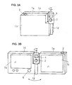
- FIG. 1A is a rear view of a first example of the first embodiment.
- Viewfinder 4 may be retracted, when display unit is used as a finder.
- FIG. 1B is a front view of the first example of the first embodiment. Viewfinder 4 is extracted, when display unit 5 is not used as a finder.
- FIG. 2A is a front view of a second example of the first embodiment. Viewfinder 4 is extracted, when display unit is not used as a finder.
- FIG. 2B is a front view during unfolding the apparatus of the second example of the first embodiment.
- FIG. 2C is a front view of the second example of the first embodiment. Viewfinder 4 is retracted, when display unit 1b on flat case lx is used as a finder.
- FIG. 3A is a front view of a third example of the first embodiment. Viewfinder 4 is fixed.
- FIG. 3B is a front view during unfolding of the third example of the first embodiment.
- FIG. 4 is a block diagram showing the configuration of the first embodiment.
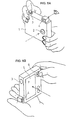
- FIG. 5A is an illustration how to take a picture, by using a viewfinder 4 and a shutter 3.
- FIG. 5B is an illustration how to take a picture, by using a display unit 5 and a scroll button 6 as a shutter.
- FIG. 6 is a rear view of a first example of the second embodiment.
- Display unit 1b is used as a finder, while scroll button 6 also functions as a shutter button.
- FIG. 7 is a front view schematic perspective view showing a second example of the second embodiment.
- Shutter button 3 is placed as conventional optical cameras.
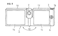
- FIG. 8 is an unfolded view of the second example as shown in Figure 7.
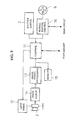
- FIG. 9 is a block diagram showing the configuration of the second embodiment.
- FIG. 10A is a front view of a first example of the third embodiment.
- Display unit lc is a finder for a subject person.
- FIG. 10B is an unfolded view of the first example as shown in Figure 10A.
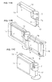
- FIG. 11A is a rear view of a second example of the third embodiment.
- Shutter button 3 is placed as conventional optical cameras.
- FIG. 11B is an unfolded view of the second example as shown in Figure 11A.
- FIG. 11C is a front view of the second example of the third embodiment.
- Display unit lc is a finder for a subject person.
- FIG. 12 is a block diagram showing the configuration of the third embodiment.
- the information terminal body 1 is equipped with a camera function unit (not shown), and an operation button 3 for a shutter arranged in a photographing optical system 2 (optical lens system, electric eye photocell or the like) is arranged on a shoulder portion la (upper side) of a case of the information terminal body 1.
- a photographing optical system 2 optical lens system, electric eye photocell or the like
- a viewfinder 4 is arranged in the shoulder portion la in alignment with the operation button 3 to cause a user to peek in, for example, a direct image from an optical path of the optical system 2 such that the viewfinder can be retracted in the information terminal body 1.
- reference numeral 5 denotes a display unit (liquid crystal screen) arranged on one surface of the information terminal body 1, and a terminal operation button 6 serving as a scroll button related to the display unit 5 is arranged beside the display unit 5.
- the terminal operation button 6 is designed such that two operation functions are added by pressing the terminal operation button 6 in two steps independently of a tilting operation for a scroll operation (to be described later).
- the information terminal body 1 shown in FIGS. 2A, 2B and 2C is designed to foldably pivot a pair of flat cases 1X and 1Y at least one (two, in this example) of which has display units 1b and 1c through a hinge portion 1Z.
- a housing 7 equipped with the photographing optical system 2 (lens opening is shown outside) of the camera function unit is arranged on the hinge portion 1Z such that the housing 7 can be pivoted about the rotation center of the hinge portion 1Z.
- the viewfinder 4 is arranged in an optical system storage unit (large-diameter portion which can be rotated about the shaft) of the hinge portion 1Z such that the viewfinder can be retracted in the optical system storage unit.
- the viewfinder 4 is directly and fixedly arranged in the optical system storage unit.
- the positions of the shutter button 3 for the shutter and the viewfinder 4 are set at the positions shown in FIG. 2 or 3.
- the shutter button 3 and the viewfinder 4 may be located any positions where the shutter button 3 and the viewfinder 4 can be easily operated as buttons of a camera.
- each of the shutter button 3 (shutter release button) and the scroll button 6 has a button switch structure of a two-step pressing type.
- the camera function unit is activated to set the device in a photographing preparation stage.
- the button is pressed in the second step, the shutter is released.
- a control circuit 11 controls a lens drive unit 12 to adjust a focal point and an exposure of the photographing optical system 2 (optical lens system), and the control circuit 11 controls an image signal processing circuit 13 and a photographing circuit 14 to perform such an adjustment that a proper image can be photographed and completes preparation for photographing.
- the shutter button 3 or the scroll button 6 When the shutter button 3 or the scroll button 6 is pressed down by two steps, the signal is input to the control circuit 11, and the shutter (not shown) of the photographing optical system 2 is released. Image information focused by the photographing circuit 14 is converted into digital image data by the image signal processing circuit 13 to be stored in a memory 15.
- control circuit 11 is connected to a main circuit of the portable information terminal.
- Digital image data stored in the memory 15 is transferred to the main circuit through the control circuit 11.
- an image may be displayed on the display unit 1b.
- the following configuration may be used. That is, for example, the case 1Y is developed at 360° with respect to the case 1X, image display is performed on the display unit 1b as a viewfinder.
- the display unit lc is caused to face a subject side, and the same screen display is performed on the display unit 1c, so that the image (so-called camera angle) as a subject can be watched from the subject side.
- the shutter button 3 serving as a shutter release button and the scroll button 6 are easily selectively operated even if a user peeks in the viewfinder 4 or even if the user watches the display unit 5 (or 1c).
- the scroll button 6 is designed to be used in not only a shutter operation function (press down) but also a screen scroll operation or a menu selection operation which is an original function. For this reason, the scroll button 6 is connected to the control circuit 11 and also connected to the main circuit of the portable information terminal.
- a scroll button control circuit 16 which can perform an operation such as a function mode switching operation may be arranged.
- the scroll button control circuit 16 may be omitted.
- the portable information terminal can achieve the function of a television telephone or the like which is the original function.
- a reception state which can also be actively turned off by the switching operation
- a camera function are set.
- the function of the information terminal is set such that a reception signal of the information terminal can be notified by generating a predetermined sound, and the shutter operation of the camera function unit is performed by a pressing operation of the shutter button 3.
- a user arbitrary selects whether the display unit 1b is used as a viewfinder or the viewfinder 4 is directly used.
- a switching operation for this selection may be performed by a switch (not shown) arranged on the terminal body.
- the viewfinder 4 When the viewfinder 4 is directly used, the screen display (output display as the function of the viewfinder) of the display unit 1b is stopped, unnecessary power is prevented from being consumed.
- a function switch such as a keyboard display is displayed on a part of the display unit 1b, while a call is made by the scroll button 6.
- the camera function unit is operated to continuously or intermittently photograph the image of a user herself/himself through the photographing optical system 2. For example, an image is displayed on a part of the display unit 1b, and an image signal is digitized and then it is transmitted to a person on the opposite end of line. An image of the person on the opposite end of line is also displayed on the display unit 1c.
- the camera function is achieved by using the photographing optical system 2, and the image can also be immediately transmitted to the other end.
- a mode switching operation may be performed by a function switch displayed on a part of the display unit 1b or the like.
- the portable information terminal with camera when the camera function is mainly operated, even if the display unit 1b of the portable information terminal is powered on to be used as a viewfinder, the viewfinder 4 which is independently arranged can be used in correspondence with the photographing optical system 2 of the camera function unit. For this reason, a power for powering the display unit 1b can be prevented from being consumed.
- the vertical press switch function set in the scroll button 6 can also be used in a function except for the shutter operation button (multiple function) to the taste of a user.
- FIGS. 6, 7, and 8 The outlines of two examples of the second embodiment are shown in FIGS. 6, 7, and 8.
- an information terminal body 1 is equipped with a camera function unit (not shown), an shutter operation button 3 for a shutter arranged in a photographing optical system 2 (optical lens system, electric eye photocell, and the like) is arranged on a shoulder portion 1a (located on a surface perpendicular to a surface having a display unit to be described later) of a case of the information terminal body 1.
- a camera function unit not shown
- an shutter operation button 3 for a shutter arranged in a photographing optical system 2 optical lens system, electric eye photocell, and the like
- a shoulder portion 1a located on a surface perpendicular to a surface having a display unit to be described later
- the same function as that of the shutter operation button 3 for the shutter is set in one function operation of a terminal operation button 6 arranged on the information terminal body 1, so that the terminal operation button 6 and the shutter operation button 3 can be used by switching.
- the terminal operation button 6 is a scroll button related to the display unit 1b of the information terminal body 1. This scroll button has not only a scroll function obtained by a normal tilting operation but also a vertical pressing function, and the function is caused to correspond to the function of the shutter operation button 3 for the shutter (the terminal operation button 6 and the shutter operation button 3 have the same functions).
- the second example of information terminal body 1 as shown in FIGS. 7 and 8 is designed to foldably pivot a pair of flat cases 1X and 1Y at least one (two, in this example) of which has display units 1c and 1d through a hinge portion 1Z.
- the hinge portion 1Z is equipped with the photographing optical system 2 of the camera function unit.
- the characteristic feature of the present invention is the same as that of the configuration shown in FIG. 6.
- the positions of the shutter operation button 3 for the shutter and the scroll button 6 are set at the positions shown in FIG. 8.
- the shutter operation button 3 and the scroll button 4 may be located at any positions.
- the shutter operation button 3 may be located at a position where the information terminal is easily operated as a camera
- the scroll button 6 may be located at a position where the scroll button is is easily operated as the shutter release button of the camera and is easily operated as the operation button of the portable information terminal.
- Each of the shutter operation button 3 (shutter release 5 button) and the scroll button 6 has a button switch structure of a two-step pressing type.
- the camera function unit is activated to set the device in a photographing preparation stage.
- the button is pressed in the second step, the shutter is released.
- a control circuit 11 comprising of a CPU and the like controls a lens drive unit 12 to adjust a focal point and an exposure of the photographing optical system 2 (optical lens system), and the control circuit 11 controls an image signal processing circuit 13 and a image-pickup circuit 14 to perform such an adjustment that a proper image can be photographed and completes preparation for photographing.
- the shutter operation button 3 or the scroll button 6 When the shutter operation button 3 or the scroll button 6 is pressed down by two steps, the signal is input to the control circuit 11, and the shutter (not shown) of the photographing optical system 2 is released. Image information focused by the image-pickup circuit 14 is converted into digital image data by the image signal processing circuit 13 to be stored in a memory 15.
- control circuit 11 is connected to a main circuit of the portable information terminal.
- Digital image data stored in the memory 15 is transferred to the main circuit through the control circuit 11.
- an image may be displayed on the display unit 1b.
- the following configuration may be used. That is, for example, the case 1Y is developed at 360° with respect to the case 1X, image display is performed on the display unit 1b as a viewfinder.
- the display unit 1c is caused to face a subject side, and the same screen display is performed on the display unit 1c, so that the image (so-called camera angle) as a subject can also be watched from the subject (person to be photographed) side. In this manner, the image of the person to be photographed can be checked.
- the scroll button 6 is designed to be used in not only a shutter operation function (press down) but also a screen scroll operation or a menu selection operation which is an original function. For this reason, the scroll button 6 is connected to the control circuit 11 and also connected to the main circuit of the portable information terminal.
- a scroll button control circuit 16 which can perform an operation such as a function mode switching operation may be arranged.
- the scroll button control circuit 16 may be omitted.
- the portable information terminal can achieve the function of a television telephone or the like which is the original function.
- a reception state which can also be actively turned off by the switching operation
- a camera function are set.
- the function of the information terminal is set such that a reception signal can be notified by generating a predetermined sound, and the shutter operation of the camera function unit is performed by a pressing operation of the operation button 3.
- a function switch such as a keyboard display is displayed on a part of the display unit 1b, while a call is made by using scroll button.
- the transmission and reception of sound can be realized, and the camera function unit is operated to continuously or intermittently photograph the image of a user herself/himself through the photographing optical system 2.
- an image is displayed on a part of the display unit 1b, and an image signal is digitized and then transmitted to a person on the other end of line.
- An image of the person on the other end of line can also be displayed on the display unit 1c.
- the photographing optical system 2 On the demand of a calling person or a called person, the photographing optical system 2 is activated, and the image can also be immediately transmitted to the other end.
- a mode switching operation may be performed by a function switch serving as a touch sensor displayed on a part of the display unit 1b or the like.
- the portable information terminal with camera even though the camera function is mainly operated, or when the original function of the portable information terminal is mainly used, an advantage that a button (for example, scroll button) operated by a user is used as an operation button for a shutter operation can be achieved.
- a button for example, scroll button
- the vertically pressing switching function set in the scroll button can also be used in a function except for the shutter operation button (multiple function) to the taste of a user.
- shutter release buttons are independent of other buttons. Therefore, when a user wants to photograph a subject with the camera while a scroll button is being operated, the user changes the holding state of the device body or the user must separate her/his finger from the scroll button and move the finger to the operation button for the shutter.
- a shutter operation function is added to the scroll button serving as a terminal operation button, a shutter operation can also be realized without using the scroll button.
- the shutter operation can also be achieved by operating a plurality of buttons 5 as shown in FIG. 6.
- the information terminal body 1 is designed such that, as shown in FIGS. 10A, 10B, a pair of flat cases 1X and 1Y having display units 1b and lc are foldably pivoted through a hinge portion 1Z, and the hinge portion 1Z is equipped with a photographing optical system 2 (lens opening is shown outside) for the camera function unit.
- One case 1X is equipped with a terminal operation button 6 as a scroll button for a screen of the display unit 1b, and the terminal operation button 6 is aligned to another terminal operation button 5.
- the terminal operation button 5 is designed (to be described later) such that not only a tilting operation for a scroll operation in a normal state but also two operation functions obtained by pressing the button in two steps.
- the cases 1X and 1Y have the display units on the outside surfaces such that the display units 1b and 1c face outside (the display units 1b and 1c are back to back on the opposite side) in a folded state.
- the hinge portion 1Z is designed to pivot a hinge portion 1d arranged on the case 1X and a hinge portion le arranged on the case 1Y with respect to the axial center (not shown) of a housing which accommodates the optical system 2 therein.
- the position of the operation button 3 for the shutter is located at the shoulder portion la shown in FIG. 10.
- the information terminal body 1 may be arranged at any position where the portable information terminal can be easily operated.
- each of the shutter operation button 3 (shutter release button) and the scroll button 6 has a button switch structure of a two-step pressing type.
- the camera function unit is activated to set the device in a photographing preparation stage.
- the button is pressed in the second step, the shutter is released.
- a control circuit 11 controls a lens drive unit 12 to adjust a focal point and an exposure of the photographing optical system 2 (optical lens system), and the control circuit 11 controls an image signal processing circuit 13 and a photographing circuit 14 to perform such an adjustment that a proper image can be photographed and completes preparation for photographing.
- the shutter operation button 3 or the scroll button 6 When the shutter operation button 3 or the scroll button 6 is pressed down by two steps, the signal is input to the control circuit 11, and the shutter (not shown) of the photographing optical system 2 is released. Image information focused by the photographing circuit 14 is converted into digital image data by the image signal processing circuit 13 to be stored in a memory 15.
- control circuit 11 is connected to a main circuit of the portable information terminal. Digital image data stored in the memory 15 is transferred to the main circuit through the control circuit 11. In this case, the image of a subject is displayed on the display unit 1b in place of a viewfinder.
- Images are displayed on the display unit 1b as a finder, and the display unit 1c is caused to face the subject.
- the same image is displayed on the display unit 1c, so that an image (so-called camera angle) which is a subject can be viewed from the subject side.
- a horizontally inverted image (for example, this is obtained by operating a line memory as so-called First in last out) of the photographed image may be displayed on the display unit 1c facing the subject side.
- the portable information terminal may have a selectable and switchable configuration (not shown) such as switching means for a normal image such that an inverted image is displayed through image inversion means 16.
- the scroll button 6 is designed to be used in not only a shutter operation function (press down) but also a screen scroll operation or a menu selection operation which is an original function. For this reason, the scroll button 6 is connected to the control circuit 11 and also connected to the main circuit of the portable information terminal.
- a scroll button control circuit 17 which can perform an operation such as a function mode switching operation may be arranged.
- the scroll button control circuit 17 may be omitted.
- the portable information terminal can achieve the function of a television telephone or the like which is the original function.
- a reception state which can also be actively turned off by the switching operation
- a camera function are set.
- the function of the information terminal is set such that a reception signal of the information terminal can be notified by generating a predetermined sound, and the shutter operation of the camera function unit is performed by a pressing operation of the shutter operation button 3.
- the display unit 1b is used as a finder.
- a function switch such as a keyboard display is displayed on a part of the display unit 1b, while the scroll button 6 is operated to make a call.
- the transmission and reception of sound can be realized, and the camera function unit is operated to continuously or intermittently photograph the image of a user herself/himself through the photographing optical system 2.
- an image is displayed on a part of the display unit 1b, and an image signal is digitized and then transmitted to a person on the other end of line, or radio communication channel.
- An image of the person on the other end can also be displayed on the display unit 1c.
- a desired photographing operation is performed by using the photographing optical system 2, and the image can also be immediately transmitted from one end to the other end.
- a mode switching operation may be performed by a function switch displayed on a part of the display unit 1b or the like.
- FIG. 10A and FIG. 11C when the display unit 1c is caused to face a subject to perform a photographing operation, for example, so that the shutter can be released after a user causes a person (person to be photographed), which is a subject, to check the image.
- the photographing operation can be performed at a preferable camera angle, and the image can be transmitted.
- the portable information terminal with camera when the camera function is mainly operated, an image to be photographed can be checked, and an image on which the intention, e.g., a camera angle or the like, of a person to be photographed is reflected can be received.
- the intention e.g., a camera angle or the like
- a hinge portion 1Z has a structure in which cases 1X and 1Y are pivoted by parallel shafts1f and 1g (indicated by dotted lines) with respect to a housing 6 equipped with a photographing optical system 2.
- two states can be selected such that display units 1b and 1c face outside and inside the device.
- the device when the portable information terminal is not used, as shown in FIG. 11A, the device is designed such that the display units 1b and 1c are opposite to each other and are not exposed to the outside.
- FIG. 11B when the portable information terminal is used as an information terminal, one case 1X is developed at 180° about the parallel shaft 1f with respect to the other case 1Y (state indicated by a solid line), or, furthermore, when the cases 1X and 1Y are horizontally drawn as indicated by a straight arrow to rotate the housing 6 at 90° about an intermediate point between the parallel shafts 1f and 1g (state indicated by an imaginary line).
- the portable information terminal can be used as a television telephone.
- the housing 6 is more rotated at 90° (rotated at 180° from the state shown in FIG. 11A) from the state shown in FIG. 11a through the state shown in FIG. 11b.
- the case 1Y is rotated at 180° about the parallel shaft 1g (i.e., rotated at 360° as a whole), so that the display units 1b and 1c can be made opposite to each other as shown in FIG. 11C.
- the image of a subject can be displayed on the display unit 1b as a viewfinder, and the same image or a horizontally inverted image can be displayed to be opposite to the display unit 1b used as a finder on the opposite side can be displayed on the display unit 1c facing the subject. For this reason, a photographing operation can be performed with an image on which a demand, related to a camera angle, of a person to be photographed is reflected.
- the vertical press switch function set in the scroll button 6 can also be used in a function except for the shutter operation button (multiple function) to the taste of a user.
- the following method of using the portable information terminal can be achieved. That is, the camera function is operated when the cases are developed at 180°, a live image serving as a viewfinder is displayed on one display unit, and the image which is previously photographed is displayed.
Priority Applications (1)
| Application Number | Priority Date | Filing Date | Title |
|---|---|---|---|
| EP10176345A EP2267999A3 (fr) | 1999-12-24 | 2000-12-21 | Terminal d'informations portable équipé d'une camera |
Applications Claiming Priority (6)
| Application Number | Priority Date | Filing Date | Title |
|---|---|---|---|
| JP36781299 | 1999-12-24 | ||
| JP36781199 | 1999-12-24 | ||
| JP36781099A JP3546996B2 (ja) | 1999-12-24 | 1999-12-24 | カメラ付き携帯情報端末装置 |
| JP36781299A JP3546997B2 (ja) | 1999-12-24 | 1999-12-24 | カメラ付き携帯情報端末装置 |
| JP36781199A JP2001183731A (ja) | 1999-12-24 | 1999-12-24 | カメラ付き携帯情報端末装置 |
| JP36781099 | 1999-12-24 |
Publications (2)
| Publication Number | Publication Date |
|---|---|
| EP1111919A2 true EP1111919A2 (fr) | 2001-06-27 |
| EP1111919A3 EP1111919A3 (fr) | 2003-07-30 |
Family
ID=27341761
Family Applications (2)
| Application Number | Title | Priority Date | Filing Date |
|---|---|---|---|
| EP10176345A Withdrawn EP2267999A3 (fr) | 1999-12-24 | 2000-12-21 | Terminal d'informations portable équipé d'une camera |
| EP00128109A Withdrawn EP1111919A3 (fr) | 1999-12-24 | 2000-12-21 | Terminal d'informations portable équipé d'une camera |
Family Applications Before (1)
| Application Number | Title | Priority Date | Filing Date |
|---|---|---|---|
| EP10176345A Withdrawn EP2267999A3 (fr) | 1999-12-24 | 2000-12-21 | Terminal d'informations portable équipé d'une camera |
Country Status (5)
| Country | Link |
|---|---|
| US (3) | US7046287B2 (fr) |
| EP (2) | EP2267999A3 (fr) |
| KR (1) | KR100415370B1 (fr) |
| CN (2) | CN1577036A (fr) |
| TW (1) | TW493340B (fr) |
Cited By (24)
| Publication number | Priority date | Publication date | Assignee | Title |
|---|---|---|---|---|
| EP1246464A2 (fr) * | 2001-03-28 | 2002-10-02 | Mitsubishi Denki Kabushiki Kaisha | Téléphone cellulaire avec dispositif de prise de vue |
| EP1298925A2 (fr) * | 2001-09-28 | 2003-04-02 | Matsushita Electric Industrial Co., Ltd. | Méthode et appareil de communication d'images animées |
| KR20030050046A (ko) * | 2001-12-18 | 2003-06-25 | 주식회사 매직아이 | 휴대용 무선 단말기의 카메라 장치 |
| WO2003077097A1 (fr) * | 2002-03-08 | 2003-09-18 | Mitsubishi Denki Kabushiki Kaisha | Dispositif de communication mobile, procede de commande d'affichage pour ledit dispositif et programme correspondant |
| EP1377017A2 (fr) * | 2002-06-12 | 2004-01-02 | Fujitsu Limited | Terminal portable |
| EP1383324A1 (fr) * | 2002-07-18 | 2004-01-21 | Fujitsu Limited | Dispositif électronique portable et système de formation d'image |
| EP1387582A1 (fr) * | 2002-07-30 | 2004-02-04 | Sharp Kabushiki Kaisha | Dispositif portable d'affichage d'une image photographique |
| EP1404121A1 (fr) * | 2002-09-30 | 2004-03-31 | Sony Ericsson Mobile Communications AB | Caméra pour visiophone mobile |
| WO2004030345A1 (fr) * | 2002-09-30 | 2004-04-08 | Sony Ericsson Mobile Communications Ab | Camera video dans un telephone mobile |
| EP1422931A1 (fr) | 2002-11-18 | 2004-05-26 | LG Electronics Inc. | Terminal mobile de communication comprenant une caméra |
| EP1455529A1 (fr) * | 2003-03-07 | 2004-09-08 | Sharp Kabushiki Kaisha | Dispositif électronique mobile multifonctionnel |
| EP1458169A2 (fr) * | 2003-03-10 | 2004-09-15 | Samsung Electronics Co., Ltd. | Terminal portable et sans fil en forme de barre |
| EP1540926A1 (fr) * | 2002-08-30 | 2005-06-15 | Fujitsu Limited | Dispositif electronique du type repliable |
| EP1548300A1 (fr) * | 2002-08-26 | 2005-06-29 | Matsushita Electric Industrial Co., Ltd. | Terminal de communication de type ouverture / fermeture et dispositif articule |
| FR2864873A1 (fr) * | 2004-01-06 | 2005-07-08 | Sagem | Telephone mobile |
| WO2006055253A3 (fr) * | 2004-11-15 | 2006-07-20 | Sony Ericsson Mobile Comm Ab | Dispositif mobile a position d'appareil photo selectionnable |
| EP1689181A1 (fr) * | 2005-02-04 | 2006-08-09 | Sagem Communication | Télephone comportant une caméra |
| EP1718038A2 (fr) * | 2002-06-21 | 2006-11-02 | Sharp Kabushiki Kaisha | Téléphone cellulaire portable et pliable avec deux dispositifs d'affichage et un appareil de photo intégré |
| EP1753239A3 (fr) * | 2005-08-12 | 2007-09-05 | LG Electronics Inc. | Terminal de communication mobile avec double écran ayant une fonction d'édition de l'image capturée et la méthode correspondante |
| US7450977B2 (en) * | 2003-07-31 | 2008-11-11 | Vodafone K.K. | Mobile communication terminal |
| EP2031855A1 (fr) | 2007-08-30 | 2009-03-04 | Aiptek International Inc. | Cadre de photo numérique avec fonction de photographie |
| WO2011141930A1 (fr) * | 2010-05-12 | 2011-11-17 | Rohan Pandey | Dispositif électronique portable équipé d'une caméra rotative |
| EP2632118A1 (fr) * | 2012-02-21 | 2013-08-28 | LG Electronics, Inc. | Terminal mobile pliable avec deux écrans d'affichage |
| DE102019005924A1 (de) * | 2019-08-22 | 2020-02-20 | Michael Nold | Mobiltelefon mit einem integrierten elektronischen Sucher |
Families Citing this family (83)
| Publication number | Priority date | Publication date | Assignee | Title |
|---|---|---|---|---|
| JP3546784B2 (ja) * | 1999-12-14 | 2004-07-28 | 日本電気株式会社 | 携帯端末 |
| JP4387546B2 (ja) * | 2000-03-22 | 2009-12-16 | 株式会社リコー | カメラ、画像入力装置、携帯端末装置およびカメラの形態変更方法 |
| FI118621B (fi) * | 2000-08-03 | 2008-01-15 | Nokia Corp | Kannettava, avatun ja suljetun käyttöasennon käsittävä, taitettava elektroninen laite sekä sen kahvajärjestely |
| US7173665B2 (en) | 2001-03-30 | 2007-02-06 | Sanyo Electric Co., Ltd. | Folding mobile communication terminal |
| KR100421994B1 (ko) * | 2001-05-21 | 2004-03-10 | 삼성전자주식회사 | 촬상장치용 뷰파인더 및 이를 구비한 캠코더 |
| JP4578727B2 (ja) * | 2001-06-19 | 2010-11-10 | パナソニック株式会社 | 回動機能付きカメラを備えた情報端末装置 |
| KR100412485B1 (ko) * | 2001-06-22 | 2003-12-31 | 삼성전자주식회사 | 자동인출가능한 촬상장치용 뷰파인더 및 이를 구비한촬상장치 |
| JP4378072B2 (ja) * | 2001-09-07 | 2009-12-02 | キヤノン株式会社 | 電子機器、撮像装置、携帯通信機器、映像の表示制御方法及びプログラム |
| KR100434455B1 (ko) * | 2001-10-12 | 2004-06-05 | 삼성전자주식회사 | 이중 힌지 장치를 구비한 플립이 제공된 휴대폰 |
| JP4313560B2 (ja) * | 2001-10-31 | 2009-08-12 | パナソニック株式会社 | 携帯電話 |
| CA2469692C (fr) * | 2001-12-19 | 2012-04-17 | Sanyo Electric Co., Ltd. | Terminal de communication pliable |
| FI113130B (fi) * | 2002-04-17 | 2004-02-27 | Nokia Corp | Kannettava, taitettava elektroninen laite, joka on varustettu puhelintoiminnoilla ja kameratoiminnoilla |
| JP4313545B2 (ja) * | 2002-05-15 | 2009-08-12 | 京セラ株式会社 | カメラ付き折畳式携帯電話装置 |
| KR100469855B1 (ko) * | 2002-09-25 | 2005-02-02 | 삼성전자주식회사 | 휴대용 통신 장치 |
| JP3914855B2 (ja) * | 2002-10-15 | 2007-05-16 | パナソニック モバイルコミュニケーションズ株式会社 | 携帯端末 |
| KR100487616B1 (ko) * | 2002-11-29 | 2005-05-03 | 엘지전자 주식회사 | 폴더형 이동통신 단말기의 액정표시화면 영상 반전 스위치장치 |
| US20050078211A1 (en) * | 2003-07-31 | 2005-04-14 | Symon Whitehorn | Handheld device with integral axial camera |
| KR100739564B1 (ko) * | 2003-07-31 | 2007-07-16 | 엘지전자 주식회사 | 카메라가 장착된 이동통신 단말기 |
| JP4048435B2 (ja) * | 2003-10-23 | 2008-02-20 | ソニー株式会社 | 電子機器 |
| US7508439B2 (en) * | 2003-11-21 | 2009-03-24 | Olympus Corporation | Digital camera having a movable image display screen |
| KR100677303B1 (ko) * | 2003-12-26 | 2007-02-05 | 엘지전자 주식회사 | 휴대 단말기 |
| KR20050075630A (ko) * | 2004-01-17 | 2005-07-21 | 삼성전자주식회사 | 영상촬영장치 |
| US8593578B1 (en) | 2004-04-23 | 2013-11-26 | Heather A. Geronimi | Electronic image display systems |
| US7352415B1 (en) * | 2004-04-23 | 2008-04-01 | Geronimi Heather A | Electronic image display systems |
| GB0411314D0 (en) * | 2004-05-21 | 2004-06-23 | Koninkl Philips Electronics Nv | Electronic device with multiple array devices |
| JP2006005579A (ja) * | 2004-06-16 | 2006-01-05 | Sony Corp | 撮像装置 |
| KR100600750B1 (ko) * | 2004-07-27 | 2006-07-14 | 엘지전자 주식회사 | 듀얼카메라가 장착된 이동통신 단말기 |
| KR101114210B1 (ko) * | 2004-07-29 | 2012-03-07 | 삼성테크윈 주식회사 | 팝업 카메라 모듈 및 이를 구비한 휴대폰 |
| KR100604323B1 (ko) * | 2004-08-28 | 2006-07-24 | 삼성테크윈 주식회사 | 내장형 카메라 장치 및 이를 구비한 휴대폰 |
| JP2006101466A (ja) * | 2004-09-03 | 2006-04-13 | Nikon Corp | デジタルスチルカメラ |
| JP4533098B2 (ja) * | 2004-11-16 | 2010-08-25 | キヤノン株式会社 | 画像表示装置、画像表示装置の表示制御方法、プログラム、及び記憶媒体 |
| US7706677B2 (en) * | 2005-01-14 | 2010-04-27 | Samsung Electro-Mechanics Co., Ltd | Mobile communication terminal device |
| US7184803B2 (en) * | 2005-01-21 | 2007-02-27 | Inventec Corporation | Apparatus for automatically projecting or retracting lens in response to the display of an electronic device incorporating the apparatus being opened or closed |
| US20060209197A1 (en) * | 2005-03-15 | 2006-09-21 | Nokia Corporation | Camera devices |
| US20070041093A1 (en) * | 2005-08-22 | 2007-02-22 | Stuart Bard | Projector screen for use in a lighted room |
| JP2008022438A (ja) * | 2006-07-14 | 2008-01-31 | Sony Corp | 撮像装置 |
| US20080231740A1 (en) * | 2007-03-21 | 2008-09-25 | Mcintyre Dale F | Camera with multiple displays |
| US20080231741A1 (en) * | 2007-03-21 | 2008-09-25 | Mcintyre Dale F | Camera with multiple displays |
| US8692930B2 (en) * | 2007-08-20 | 2014-04-08 | Matthew Rolston Photographer, Inc. | Mobile device with operation for modifying visual perception |
| JP4260215B1 (ja) * | 2007-08-29 | 2009-04-30 | 任天堂株式会社 | 撮像装置 |
| EP2039398B1 (fr) | 2007-08-29 | 2016-05-04 | Nintendo Co., Ltd. | Appareil photographique |
| US8177441B2 (en) | 2007-08-29 | 2012-05-15 | Nintendo Co., Ltd. | Imaging apparatus |
| US8917985B2 (en) * | 2007-08-29 | 2014-12-23 | Nintendo Co., Ltd. | Imaging apparatus |
| US20100299710A1 (en) * | 2007-09-20 | 2010-11-25 | Samsung Electronics Co. Ltd. | Method for inputting user command and video apparatus and input apparatus employing the same |
| KR101470413B1 (ko) * | 2007-09-20 | 2014-12-10 | 삼성전자주식회사 | 사용자 명령 입력 방법 및 이를 적용한 영상기기와입력기기 |
| JP2009199000A (ja) * | 2008-02-25 | 2009-09-03 | Funai Electric Co Ltd | 画像撮影装置 |
| US8130275B2 (en) | 2008-06-13 | 2012-03-06 | Nintendo Co., Ltd. | Information-processing apparatus, and storage medium storing a photographing application launch program executed by information-processing apparatus |
| JP4181211B1 (ja) | 2008-06-13 | 2008-11-12 | 任天堂株式会社 | 情報処理装置およびそれにおいて実行される起動用プログラム |
| US8089749B2 (en) * | 2008-07-18 | 2012-01-03 | Nokia Corporation | Easy opening folding type device |
| US8848100B2 (en) * | 2008-10-01 | 2014-09-30 | Nintendo Co., Ltd. | Information processing device, information processing system, and launch program and storage medium storing the same providing photographing functionality |
| WO2010048463A1 (fr) * | 2008-10-22 | 2010-04-29 | Silverlink International Ltd. | Dispositif de capture d’image à viseur avant réglable |
| JP5414303B2 (ja) * | 2009-02-24 | 2014-02-12 | 京セラ株式会社 | 携帯電子機器及びその制御方法 |
| US20100225773A1 (en) * | 2009-03-09 | 2010-09-09 | Apple Inc. | Systems and methods for centering a photograph without viewing a preview of the photograph |
| KR101635205B1 (ko) * | 2009-08-19 | 2016-06-30 | 삼성전자주식회사 | 휴대용 통신 장치의 팝업 장치 |
| KR101622635B1 (ko) * | 2010-02-12 | 2016-05-20 | 삼성전자주식회사 | 3개의 표시부를 가지는 단말기의 데이터 운용 방법 및 이를 지원하는 단말기 |
| US8878794B2 (en) * | 2011-09-27 | 2014-11-04 | Z124 | State of screen info: easel |
| KR101817656B1 (ko) * | 2011-12-13 | 2018-01-12 | 삼성전자주식회사 | 다기능 디스플레이를 구비하는 카메라 |
| US8825123B1 (en) * | 2012-10-16 | 2014-09-02 | Juan Carlos Gudino | Passthrough case for a smart phone |
| JP6124607B2 (ja) * | 2013-01-28 | 2017-05-10 | キヤノン株式会社 | 撮像装置 |
| WO2014136521A1 (fr) * | 2013-03-06 | 2014-09-12 | Necカシオモバイルコミュニケーションズ株式会社 | Dispositif de formation d'image, procédé de formation d'image, et programme |
| US9413968B2 (en) * | 2013-04-04 | 2016-08-09 | Samsung Electronics Co., Ltd. | Camera apparatus and wireless communication terminal including the same |
| LU92208B1 (en) * | 2013-06-07 | 2014-12-08 | Andrzej Jaroslaw Galuszka | Mobile phone or portable PC with a camera |
| JP6299227B2 (ja) | 2014-01-16 | 2018-03-28 | ソニー株式会社 | カメラ装置 |
| KR102358935B1 (ko) | 2014-02-12 | 2022-02-04 | 가부시키가이샤 한도오따이 에네루기 켄큐쇼 | 전자 기기 |
| US9712749B2 (en) * | 2014-02-27 | 2017-07-18 | Google Technology Holdings LLC | Electronic device having multiple sides |
| TWI679624B (zh) * | 2014-05-02 | 2019-12-11 | 日商半導體能源研究所股份有限公司 | 半導體裝置 |
| US10136068B2 (en) * | 2014-05-08 | 2018-11-20 | Sony Corporation | Imaging apparatus |
| WO2015170521A1 (fr) * | 2014-05-08 | 2015-11-12 | ソニー株式会社 | Dispositif imageur |
| US9729766B2 (en) * | 2014-05-19 | 2017-08-08 | Ricoh Imaging Company, Ltd. | Hinge structure, support structure and electric apparatus |
| CN204049606U (zh) * | 2014-07-22 | 2014-12-31 | 芯发威达电子(上海)有限公司 | 可自动调整影像画面的咽喉镜 |
| CN104301660A (zh) * | 2014-10-31 | 2015-01-21 | 四川量迅科技有限公司 | 一种便携式图像通信设备 |
| CN104539843A (zh) * | 2014-12-18 | 2015-04-22 | 深圳市金立通信设备有限公司 | 一种终端拍摄的方法 |
| JP5913718B1 (ja) * | 2015-11-11 | 2016-04-27 | 稔 稲葉 | ディジタルカメラ |
| WO2018080442A1 (fr) | 2016-10-25 | 2018-05-03 | Hewlett-Packard Development Company, L.P. | Sélection de modes de caméra pour dispositifs électroniques ayant multiples panneaux d'affichage |
| US10440263B2 (en) * | 2017-05-12 | 2019-10-08 | Microsoft Technology Licensing, Llc | Synchronized display on hinged multi-screen device |
| US10264186B2 (en) | 2017-06-30 | 2019-04-16 | Microsoft Technology Licensing, Llc | Dynamic control of camera resources in a device with multiple displays |
| CN110445904A (zh) * | 2018-05-04 | 2019-11-12 | Oppo广东移动通信有限公司 | 移动终端及其控制方法 |
| WO2019210730A1 (fr) * | 2018-05-04 | 2019-11-07 | Guangdong Oppo Mobile Telecommunications Corp., Ltd. | Terminal mobile |
| JP7190507B2 (ja) * | 2018-05-04 | 2022-12-15 | オッポ広東移動通信有限公司 | 移動端末 |
| US20200191368A1 (en) * | 2018-12-18 | 2020-06-18 | Toniesha Teshell Reed | Built in pop up 360 degree swivel tri-LED light for smartphone/tablet |
| US10958845B2 (en) * | 2019-04-16 | 2021-03-23 | Microsoft Technology Licensing, Llc | Camera with rotatable sensor |
| JP7453340B2 (ja) * | 2019-09-10 | 2024-03-19 | インテル コーポレイション | 移動可能なアクセサリハウジングを備えたラップトップコンピュータ |
| KR20210072351A (ko) * | 2019-12-09 | 2021-06-17 | 삼성전자주식회사 | 회전이 가능한 카메라를 구비한 폴더블 전자 장치 및 이를 이용한 촬영 방법 |
Citations (1)
| Publication number | Priority date | Publication date | Assignee | Title |
|---|---|---|---|---|
| EP0898405A2 (fr) * | 1997-08-22 | 1999-02-24 | Hitachi, Ltd. | Dispositif terminal de communication d'information |
Family Cites Families (37)
| Publication number | Priority date | Publication date | Assignee | Title |
|---|---|---|---|---|
| JP2587259B2 (ja) | 1987-12-18 | 1997-03-05 | ヤンマー農機株式会社 | 田植機の植付調節装置 |
| JPH0311657A (ja) | 1989-06-07 | 1991-01-18 | Nec Eng Ltd | Rom実装のマイクロコンピュータ |
| JP3020329B2 (ja) | 1991-10-29 | 2000-03-15 | 京セラ株式会社 | ノート形ディジタル電子カメラ |
| JP2587259Y2 (ja) | 1992-08-25 | 1998-12-16 | 茂 寺田 | ファックス機能付き携帯電話 |
| US5363089A (en) | 1992-09-24 | 1994-11-08 | Motorola, Inc. | Electronic device having multi-position hinged mechanism |
| JP3059841B2 (ja) | 1992-10-15 | 2000-07-04 | 京セラ株式会社 | 携帯電話機能付電子スチルカメラ |
| JP3255995B2 (ja) * | 1992-10-23 | 2002-02-12 | 株式会社日立製作所 | テレビ電話装置 |
| JPH06150069A (ja) | 1992-11-09 | 1994-05-31 | Oki Electric Ind Co Ltd | 光学的文字認識装置及び該装置の辞書を備えた計数機器読取装置 |
| US5550754A (en) | 1994-05-13 | 1996-08-27 | Videoptic Research | Teleconferencing camcorder |
| JP3496207B2 (ja) * | 1994-06-22 | 2004-02-09 | ソニー株式会社 | ビデオカメラ |
| JPH0822343A (ja) | 1994-07-07 | 1996-01-23 | Olympus Optical Co Ltd | 情報処理装置 |
| US5666159A (en) | 1995-04-24 | 1997-09-09 | Eastman Kodak Company | Electronic camera system with programmable transmission capability |
| JPH1051665A (ja) | 1996-04-15 | 1998-02-20 | Sony Corp | 携帯型情報処理装置及び電子カメラ |
| US6510325B1 (en) * | 1996-04-19 | 2003-01-21 | Mack, Ii Gawins A. | Convertible portable telephone |
| JP3380835B2 (ja) * | 1996-06-06 | 2003-02-24 | シャープ株式会社 | 携帯型テレビ電話 |
| FI103372B1 (fi) * | 1996-06-20 | 1999-06-15 | Nokia Telecommunications Oy | Menetelmä ja järjestelmä hätäliikenteen varmistamiseksi |
| JP3842876B2 (ja) * | 1996-09-27 | 2006-11-08 | 株式会社リコー | デジタルカメラ |
| US6441854B2 (en) * | 1997-02-20 | 2002-08-27 | Eastman Kodak Company | Electronic camera with quick review of last captured image |
| US5896600A (en) * | 1997-02-26 | 1999-04-27 | Mills; Richard | Mounting bracket for use on a toilet seat ring |
| JP3496445B2 (ja) * | 1997-04-07 | 2004-02-09 | 松下電器産業株式会社 | 軸体回転装置 |
| JP3809723B2 (ja) | 1997-04-11 | 2006-08-16 | カシオ計算機株式会社 | 複合機器 |
| JPH10313452A (ja) | 1997-05-12 | 1998-11-24 | Funai Electric Co Ltd | 携帯無線通信機 |
| JPH1124567A (ja) | 1997-07-03 | 1999-01-29 | Dainippon Printing Co Ltd | 繰り返し使用可能な名札、値札等のプレート類 |
| US6122003A (en) | 1997-08-22 | 2000-09-19 | Flashpoint Technology, Inc. | Method and apparatus for changing operating modes of an image capture device |
| KR100257330B1 (ko) * | 1997-09-04 | 2000-05-15 | 유무성 | 휴대폰겸용디지탈스틸카메라의구조 |
| JP4464471B2 (ja) | 1997-10-23 | 2010-05-19 | 富士通株式会社 | 携帯電話機 |
| JP3850120B2 (ja) | 1997-10-30 | 2006-11-29 | 京セラ株式会社 | デジタル電子カメラ |
| US6628333B1 (en) * | 1997-11-12 | 2003-09-30 | International Business Machines Corporation | Digital instant camera having a printer |
| JP3085268B2 (ja) | 1997-11-28 | 2000-09-04 | 日本電気株式会社 | 選択ダイヤル装置および携帯デバイス |
| KR100274623B1 (ko) * | 1997-12-23 | 2000-12-15 | 윤종용 | 디지털 스틸 카메라 |
| US7046286B1 (en) * | 1997-12-24 | 2006-05-16 | Canon Kabushiki Kaisha | Video camera |
| WO1999034600A1 (fr) * | 1997-12-24 | 1999-07-08 | I-See-You Corporation | Systeme visiophone autonome portatif |
| JPH11205761A (ja) | 1998-01-14 | 1999-07-30 | Mitsubishi Electric Corp | カメラ機能付携帯電話装置 |
| KR19990070408A (ko) * | 1998-02-19 | 1999-09-15 | 윤종용 | 영상정보를 송신하는 디지털 스틸 카메라 및 그 송신 방법 |
| FI112573B (fi) | 1998-06-04 | 2003-12-15 | Nokia Corp | Kamerallinen matkaviestin |
| KR19990046292A (ko) * | 1999-02-03 | 1999-07-05 | 오병호 | 사진촬영이가능한휴대폰 |
| JP2000253113A (ja) | 1999-02-26 | 2000-09-14 | Hitachi Ltd | 情報通信端末装置 |
-
2000
- 2000-12-11 US US09/733,033 patent/US7046287B2/en not_active Expired - Fee Related
- 2000-12-20 TW TW089127356A patent/TW493340B/zh not_active IP Right Cessation
- 2000-12-21 CN CNA2004100577231A patent/CN1577036A/zh active Pending
- 2000-12-21 EP EP10176345A patent/EP2267999A3/fr not_active Withdrawn
- 2000-12-21 EP EP00128109A patent/EP1111919A3/fr not_active Withdrawn
- 2000-12-21 CN CNB2004100577246A patent/CN100549796C/zh not_active Expired - Fee Related
- 2000-12-23 KR KR10-2000-0081097A patent/KR100415370B1/ko not_active IP Right Cessation
-
2006
- 2006-01-25 US US11/338,769 patent/US7626630B2/en not_active Expired - Fee Related
-
2009
- 2009-02-27 US US12/379,733 patent/US20090174803A1/en not_active Abandoned
Patent Citations (1)
| Publication number | Priority date | Publication date | Assignee | Title |
|---|---|---|---|---|
| EP0898405A2 (fr) * | 1997-08-22 | 1999-02-24 | Hitachi, Ltd. | Dispositif terminal de communication d'information |
Cited By (52)
| Publication number | Priority date | Publication date | Assignee | Title |
|---|---|---|---|---|
| EP1246464A3 (fr) * | 2001-03-28 | 2002-11-13 | Mitsubishi Denki Kabushiki Kaisha | Téléphone cellulaire avec dispositif de prise de vue |
| EP1246464A2 (fr) * | 2001-03-28 | 2002-10-02 | Mitsubishi Denki Kabushiki Kaisha | Téléphone cellulaire avec dispositif de prise de vue |
| US6882864B2 (en) | 2001-03-28 | 2005-04-19 | Mitsubishi Denki Kabushiki Kaisha | Cellular phone with imaging device |
| EP1298925A3 (fr) * | 2001-09-28 | 2004-04-07 | Matsushita Electric Industrial Co., Ltd. | Méthode et appareil de communication d'images animées |
| EP1298925A2 (fr) * | 2001-09-28 | 2003-04-02 | Matsushita Electric Industrial Co., Ltd. | Méthode et appareil de communication d'images animées |
| US6833857B2 (en) | 2001-09-28 | 2004-12-21 | Matsushita Electric Industrial Co., Ltd. | Moving picture communication method and apparatus |
| KR20030050046A (ko) * | 2001-12-18 | 2003-06-25 | 주식회사 매직아이 | 휴대용 무선 단말기의 카메라 장치 |
| WO2003077097A1 (fr) * | 2002-03-08 | 2003-09-18 | Mitsubishi Denki Kabushiki Kaisha | Dispositif de communication mobile, procede de commande d'affichage pour ledit dispositif et programme correspondant |
| EP1377017A2 (fr) * | 2002-06-12 | 2004-01-02 | Fujitsu Limited | Terminal portable |
| US7797020B2 (en) | 2002-06-21 | 2010-09-14 | Sharp Kabushiki Kaisha | Foldable cellular telephone |
| EP1718038A3 (fr) * | 2002-06-21 | 2007-07-04 | Sharp Kabushiki Kaisha | Téléphone cellulaire portable et pliable avec deux dispositifs d'affichage et un appareil de photo intégré |
| US7805164B2 (en) | 2002-06-21 | 2010-09-28 | Sharp Kabushiki Kaisha | Foldable cellular telephone |
| EP1718037A2 (fr) * | 2002-06-21 | 2006-11-02 | Sharp Kabushiki Kaisha | Téléphone cellulaire portable et pliable avec deux dispositifs d'affichage et un appareil de photo intégré |
| US7778661B2 (en) | 2002-06-21 | 2010-08-17 | Sharp Kabushiki Kaisha | Foldable cellular telephone |
| US7835775B2 (en) | 2002-06-21 | 2010-11-16 | Sharp Kabushiki Kaisha | Foldable cellular telephone |
| EP1718038A2 (fr) * | 2002-06-21 | 2006-11-02 | Sharp Kabushiki Kaisha | Téléphone cellulaire portable et pliable avec deux dispositifs d'affichage et un appareil de photo intégré |
| EP1718037A3 (fr) * | 2002-06-21 | 2007-07-04 | Sharp Kabushiki Kaisha | Téléphone cellulaire portable et pliable avec deux dispositifs d'affichage et un appareil de photo intégré |
| US7809413B2 (en) | 2002-06-21 | 2010-10-05 | Sharp Kabushiki Kaisha | Foldable cellular telephone |
| US7471966B2 (en) | 2002-06-21 | 2008-12-30 | Sharp Kabushiki Kaisha | Foldable cellular telephone |
| US7577461B2 (en) | 2002-06-21 | 2009-08-18 | Sharp Kabushiki Kaisha | Foldable cellular telephone |
| EP1383324A1 (fr) * | 2002-07-18 | 2004-01-21 | Fujitsu Limited | Dispositif électronique portable et système de formation d'image |
| US7190968B2 (en) | 2002-07-30 | 2007-03-13 | Sharp Kabushiki Kaisha | Portable device displaying an image provided by photographing |
| EP1387582A1 (fr) * | 2002-07-30 | 2004-02-04 | Sharp Kabushiki Kaisha | Dispositif portable d'affichage d'une image photographique |
| EP1548300A4 (fr) * | 2002-08-26 | 2009-06-24 | Panasonic Corp | Terminal de communication de type ouverture / fermeture et dispositif articule |
| EP1548300A1 (fr) * | 2002-08-26 | 2005-06-29 | Matsushita Electric Industrial Co., Ltd. | Terminal de communication de type ouverture / fermeture et dispositif articule |
| EP1540926A1 (fr) * | 2002-08-30 | 2005-06-15 | Fujitsu Limited | Dispositif electronique du type repliable |
| US7710495B2 (en) | 2002-09-30 | 2010-05-04 | Sony Ericsson Mobile Communications Ab | Portable communication apparatus with camera and extended optical path |
| EP1404121A1 (fr) * | 2002-09-30 | 2004-03-31 | Sony Ericsson Mobile Communications AB | Caméra pour visiophone mobile |
| WO2004030345A1 (fr) * | 2002-09-30 | 2004-04-08 | Sony Ericsson Mobile Communications Ab | Camera video dans un telephone mobile |
| EP1422931A1 (fr) | 2002-11-18 | 2004-05-26 | LG Electronics Inc. | Terminal mobile de communication comprenant une caméra |
| EP1569450A1 (fr) * | 2003-03-07 | 2005-08-31 | Sharp Kabushiki Kaisha | Dispositif électronique mobile multifontionnel |
| EP1455529A1 (fr) * | 2003-03-07 | 2004-09-08 | Sharp Kabushiki Kaisha | Dispositif électronique mobile multifonctionnel |
| US7126626B2 (en) | 2003-03-07 | 2006-10-24 | Sharp Kabushiki Kaisha | Multifunctional mobile electronic device |
| EP1458169A3 (fr) * | 2003-03-10 | 2007-07-25 | Samsung Electronics Co., Ltd. | Terminal portable et sans fil en forme de barre |
| EP1458169A2 (fr) * | 2003-03-10 | 2004-09-15 | Samsung Electronics Co., Ltd. | Terminal portable et sans fil en forme de barre |
| US7450977B2 (en) * | 2003-07-31 | 2008-11-11 | Vodafone K.K. | Mobile communication terminal |
| EP1562353A2 (fr) * | 2004-01-06 | 2005-08-10 | Sagem SA | Téléphone pliable avec une caméra dans la charnière |
| EP1562353A3 (fr) * | 2004-01-06 | 2009-07-15 | Sagem Communication | Téléphone pliable avec une caméra dans la charnière |
| FR2864873A1 (fr) * | 2004-01-06 | 2005-07-08 | Sagem | Telephone mobile |
| US7565183B2 (en) | 2004-11-15 | 2009-07-21 | Sony Ericsson Mobile Communications Ab | Mobile device with selectable camera position |
| WO2006055253A3 (fr) * | 2004-11-15 | 2006-07-20 | Sony Ericsson Mobile Comm Ab | Dispositif mobile a position d'appareil photo selectionnable |
| FR2881909A1 (fr) * | 2005-02-04 | 2006-08-11 | Sagem | Telephone comportant une camera |
| EP1689181A1 (fr) * | 2005-02-04 | 2006-08-09 | Sagem Communication | Télephone comportant une caméra |
| EP1753239A3 (fr) * | 2005-08-12 | 2007-09-05 | LG Electronics Inc. | Terminal de communication mobile avec double écran ayant une fonction d'édition de l'image capturée et la méthode correspondante |
| US7471890B2 (en) | 2005-08-12 | 2008-12-30 | Lg Electronics Inc. | Mobile communication terminal with dual-display unit having function of editing captured image and method thereof |
| US8605005B2 (en) | 2005-08-12 | 2013-12-10 | Lg Electronics Inc. | Mobile communication terminal with dual-display unit having function of editing captured image and method thereof |
| US8605007B2 (en) | 2005-08-12 | 2013-12-10 | Lg Electronics Inc. | Mobile communication terminal with dual-display unit having function of editing captured image and method thereof |
| EP2031855A1 (fr) | 2007-08-30 | 2009-03-04 | Aiptek International Inc. | Cadre de photo numérique avec fonction de photographie |
| WO2011141930A1 (fr) * | 2010-05-12 | 2011-11-17 | Rohan Pandey | Dispositif électronique portable équipé d'une caméra rotative |
| EP2632118A1 (fr) * | 2012-02-21 | 2013-08-28 | LG Electronics, Inc. | Terminal mobile pliable avec deux écrans d'affichage |
| US9173306B2 (en) | 2012-02-21 | 2015-10-27 | Lg Electronics Inc. | Mobile device |
| DE102019005924A1 (de) * | 2019-08-22 | 2020-02-20 | Michael Nold | Mobiltelefon mit einem integrierten elektronischen Sucher |
Also Published As
| Publication number | Publication date |
|---|---|
| EP2267999A2 (fr) | 2010-12-29 |
| CN1577036A (zh) | 2005-02-09 |
| TW493340B (en) | 2002-07-01 |
| KR20010070348A (ko) | 2001-07-25 |
| US7046287B2 (en) | 2006-05-16 |
| US7626630B2 (en) | 2009-12-01 |
| KR100415370B1 (ko) | 2004-01-16 |
| US20090174803A1 (en) | 2009-07-09 |
| US20010005454A1 (en) | 2001-06-28 |
| US20060125946A1 (en) | 2006-06-15 |
| CN100549796C (zh) | 2009-10-14 |
| EP1111919A3 (fr) | 2003-07-30 |
| CN1577037A (zh) | 2005-02-09 |
| EP2267999A3 (fr) | 2012-04-18 |
Similar Documents
| Publication | Publication Date | Title |
|---|---|---|
| US7046287B2 (en) | Portable information terminal equipped with camera | |
| JP3546997B2 (ja) | カメラ付き携帯情報端末装置 | |
| JP4053444B2 (ja) | 携帯可能な多機能電子機器 | |
| JP3948387B2 (ja) | ディジタルカメラおよびディジタルカメラ付き携帯電話装置 | |
| JP5294889B2 (ja) | 撮像装置及び撮像方法 | |
| JP4371016B2 (ja) | 電子機器 | |
| JP2004233527A (ja) | 携帯端末 | |
| JP3893958B2 (ja) | 携帯端末 | |
| JP2005051531A (ja) | 携帯機器 | |
| JP4257508B2 (ja) | 電子カメラ | |
| JP2004193860A (ja) | 電子機器 | |
| JP2004274777A (ja) | 携帯可能な多機能電子機器 | |
| JPH0239790A (ja) | テレビ電話機 | |
| JP3546996B2 (ja) | カメラ付き携帯情報端末装置 | |
| JP4186712B2 (ja) | 携帯端末装置 | |
| JP4426265B2 (ja) | カメラ付携帯電話機 | |
| JP2001183731A (ja) | カメラ付き携帯情報端末装置 | |
| KR100531162B1 (ko) | 디스플레이부의 방향에 따른 화면 표시 제어 기능을가지는 무선통신 단말기 및 그 방법 | |
| JP2003333141A (ja) | 携帯電話装置 | |
| JP2004274405A (ja) | カメラ機能付き電子機器 | |
| KR100504816B1 (ko) | 이동 통신 단말기의 영상 표시 방법 | |
| JP2011072019A (ja) | 携帯電話機 | |
| JP2000138852A (ja) | ビデオカメラ | |
| JP2003101619A (ja) | 携帯端末 | |
| KR20040103534A (ko) | 카메라 내장형 이동 통신 단말기의 외부 표시창을뷰파인더로 사용하는 방법 |
Legal Events
| Date | Code | Title | Description |
|---|---|---|---|
| PUAI | Public reference made under article 153(3) epc to a published international application that has entered the european phase |
Free format text: ORIGINAL CODE: 0009012 |
|
| AK | Designated contracting states |
Kind code of ref document: A2 Designated state(s): AT BE CH CY DE DK ES FI FR GB GR IE IT LI LU MC NL PT SE TR |
|
| AX | Request for extension of the european patent |
Free format text: AL;LT;LV;MK;RO;SI |
|
| PUAL | Search report despatched |
Free format text: ORIGINAL CODE: 0009013 |
|
| AK | Designated contracting states |
Designated state(s): AT BE CH CY DE DK ES FI FR GB GR IE IT LI LU MC NL PT SE TR |
|
| AX | Request for extension of the european patent |
Extension state: AL LT LV MK RO SI |
|
| 17P | Request for examination filed |
Effective date: 20030618 |
|
| AKX | Designation fees paid |
Designated state(s): DE FR GB |
|
| 17Q | First examination report despatched |
Effective date: 20061220 |
|
| RAP1 | Party data changed (applicant data changed or rights of an application transferred) |
Owner name: NEC PERSONAL COMPUTERS, LTD. |
|
| STAA | Information on the status of an ep patent application or granted ep patent |
Free format text: STATUS: THE APPLICATION IS DEEMED TO BE WITHDRAWN |
|
| 18D | Application deemed to be withdrawn |
Effective date: 20150929 |