EP1102337A1 - Batterie auxiliaire - Google Patents
Batterie auxiliaire Download PDFInfo
- Publication number
- EP1102337A1 EP1102337A1 EP00915443A EP00915443A EP1102337A1 EP 1102337 A1 EP1102337 A1 EP 1102337A1 EP 00915443 A EP00915443 A EP 00915443A EP 00915443 A EP00915443 A EP 00915443A EP 1102337 A1 EP1102337 A1 EP 1102337A1
- Authority
- EP
- European Patent Office
- Prior art keywords
- electrode plate
- current
- negative electrode
- positive electrode
- plate group
- Prior art date
- Legal status (The legal status is an assumption and is not a legal conclusion. Google has not performed a legal analysis and makes no representation as to the accuracy of the status listed.)
- Withdrawn
Links
Images


Classifications
-
- H—ELECTRICITY
- H01—ELECTRIC ELEMENTS
- H01M—PROCESSES OR MEANS, e.g. BATTERIES, FOR THE DIRECT CONVERSION OF CHEMICAL ENERGY INTO ELECTRICAL ENERGY
- H01M50/00—Constructional details or processes of manufacture of the non-active parts of electrochemical cells other than fuel cells, e.g. hybrid cells
- H01M50/50—Current conducting connections for cells or batteries
- H01M50/531—Electrode connections inside a battery casing
- H01M50/538—Connection of several leads or tabs of wound or folded electrode stacks
-
- H—ELECTRICITY
- H01—ELECTRIC ELEMENTS
- H01M—PROCESSES OR MEANS, e.g. BATTERIES, FOR THE DIRECT CONVERSION OF CHEMICAL ENERGY INTO ELECTRICAL ENERGY
- H01M50/00—Constructional details or processes of manufacture of the non-active parts of electrochemical cells other than fuel cells, e.g. hybrid cells
- H01M50/50—Current conducting connections for cells or batteries
- H01M50/531—Electrode connections inside a battery casing
- H01M50/533—Electrode connections inside a battery casing characterised by the shape of the leads or tabs
-
- Y—GENERAL TAGGING OF NEW TECHNOLOGICAL DEVELOPMENTS; GENERAL TAGGING OF CROSS-SECTIONAL TECHNOLOGIES SPANNING OVER SEVERAL SECTIONS OF THE IPC; TECHNICAL SUBJECTS COVERED BY FORMER USPC CROSS-REFERENCE ART COLLECTIONS [XRACs] AND DIGESTS
- Y02—TECHNOLOGIES OR APPLICATIONS FOR MITIGATION OR ADAPTATION AGAINST CLIMATE CHANGE
- Y02E—REDUCTION OF GREENHOUSE GAS [GHG] EMISSIONS, RELATED TO ENERGY GENERATION, TRANSMISSION OR DISTRIBUTION
- Y02E60/00—Enabling technologies; Technologies with a potential or indirect contribution to GHG emissions mitigation
- Y02E60/10—Energy storage using batteries
-
- Y—GENERAL TAGGING OF NEW TECHNOLOGICAL DEVELOPMENTS; GENERAL TAGGING OF CROSS-SECTIONAL TECHNOLOGIES SPANNING OVER SEVERAL SECTIONS OF THE IPC; TECHNICAL SUBJECTS COVERED BY FORMER USPC CROSS-REFERENCE ART COLLECTIONS [XRACs] AND DIGESTS
- Y02—TECHNOLOGIES OR APPLICATIONS FOR MITIGATION OR ADAPTATION AGAINST CLIMATE CHANGE
- Y02P—CLIMATE CHANGE MITIGATION TECHNOLOGIES IN THE PRODUCTION OR PROCESSING OF GOODS
- Y02P70/00—Climate change mitigation technologies in the production process for final industrial or consumer products
- Y02P70/50—Manufacturing or production processes characterised by the final manufactured product
-
- Y—GENERAL TAGGING OF NEW TECHNOLOGICAL DEVELOPMENTS; GENERAL TAGGING OF CROSS-SECTIONAL TECHNOLOGIES SPANNING OVER SEVERAL SECTIONS OF THE IPC; TECHNICAL SUBJECTS COVERED BY FORMER USPC CROSS-REFERENCE ART COLLECTIONS [XRACs] AND DIGESTS
- Y10—TECHNICAL SUBJECTS COVERED BY FORMER USPC
- Y10T—TECHNICAL SUBJECTS COVERED BY FORMER US CLASSIFICATION
- Y10T29/00—Metal working
- Y10T29/49—Method of mechanical manufacture
- Y10T29/49002—Electrical device making
- Y10T29/49108—Electric battery cell making
- Y10T29/4911—Electric battery cell making including sealing
-
- Y—GENERAL TAGGING OF NEW TECHNOLOGICAL DEVELOPMENTS; GENERAL TAGGING OF CROSS-SECTIONAL TECHNOLOGIES SPANNING OVER SEVERAL SECTIONS OF THE IPC; TECHNICAL SUBJECTS COVERED BY FORMER USPC CROSS-REFERENCE ART COLLECTIONS [XRACs] AND DIGESTS
- Y10—TECHNICAL SUBJECTS COVERED BY FORMER USPC
- Y10T—TECHNICAL SUBJECTS COVERED BY FORMER US CLASSIFICATION
- Y10T29/00—Metal working
- Y10T29/49—Method of mechanical manufacture
- Y10T29/49002—Electrical device making
- Y10T29/49108—Electric battery cell making
- Y10T29/49114—Electric battery cell making including adhesively bonding
-
- Y—GENERAL TAGGING OF NEW TECHNOLOGICAL DEVELOPMENTS; GENERAL TAGGING OF CROSS-SECTIONAL TECHNOLOGIES SPANNING OVER SEVERAL SECTIONS OF THE IPC; TECHNICAL SUBJECTS COVERED BY FORMER USPC CROSS-REFERENCE ART COLLECTIONS [XRACs] AND DIGESTS
- Y10—TECHNICAL SUBJECTS COVERED BY FORMER USPC
- Y10T—TECHNICAL SUBJECTS COVERED BY FORMER US CLASSIFICATION
- Y10T29/00—Metal working
- Y10T29/49—Method of mechanical manufacture
- Y10T29/49002—Electrical device making
- Y10T29/49108—Electric battery cell making
- Y10T29/49115—Electric battery cell making including coating or impregnating
Definitions
- the present invention relates to rechargeable batteries, and in particular to rechargeable batteries wherein an electrode plate group obtained by superimposing a positive electrode plate, in which positive electrode material is attached to a current collector, onto a negative electrode plate, in which negative electrode material is attached to a current collector, with a separator therebetween, is accommodated in a battery container together with electrolyte.
- lithium ion rechargeable batteries employing a carbon-based material as the negative electrode active material and a transition metal oxide containing lithium, such as LiCoO 2 , as the positive electrode active material have been put into practice by various companies.
- Lithium rechargeable batteries in which metallic lithium or lithium alloy is employed as the negative electrode active material had the problem that the lithium precipitated on the negative electrode as charging proceeded.
- lithium ion rechargeable batteries are free of such problem and so have excellent cycle characteristics. As a result, there has been vigorous development of lithium ion rechargeable batteries and their use in electronic equipment has become more common.
- Lithium rechargeable batteries are studied also as a means for solving global environmental problems or energy problems. As a way of guaranteeing power stability while maintaining a good global environment, implementation of technology for load equalization is desired; considerable benefits in terms of load equalization could be expected if use of small-scale battery power storage devices capable of storing power during the night could be made common in ordinary households etc. In order to prevent atmospheric pollution by car exhaust gases and global warming due to CO 2 , it would also be desirable to extend the use of electric vehicles in which some or all of the motive power is obtained by rechargeable batteries. Large lithium ion rechargeable batteries with a cell capacity of about 100 Ah are therefore being developed for use as battery power storage devices for domestic use and as power sources for electric vehicles.
- FIG. 5 The construction of such a lithium ion rechargeable battery is shown in Figure 5.
- An electrode plate group 30 constituted by superimposing a positive electrode plate 21, in which positive electrode material 21a is attached to a positive electrode current collector 21b, and a negative electrode plate 22, in which negative electrode material 22a is attached to a negative electrode current collector 22b, wound in spiral fashion with a separator 23 therebetween are accommodated in a battery container 24 comprising a battery case 25 and a battery closure 26 together with electrolyte.
- a positive electrode current collector tab 28 with one end joined to a suitable location of the positive electrode current collector 21b has its other end connected to the inner surface of the battery closure 26 constituting the positive electrode terminal, while a negative electrode current collector tab 29 with one end joined to a suitable location of the negative electrode current collector 22b has its other end connected to the inside bottom surface of the battery case 25 constituting the negative electrode terminal.
- An insulating packing 27 is interposed between the inner circumference of the top end aperture of the battery case 25 and the outer circumference of the battery closure 26 so as to mutually insulate the battery case 25 and the battery closure 26 and to seal the battery container 24.
- Laid-open Japanese Patent Application No. 8-115744 discloses an electrode plate group which is directed to solve these problems.
- current collectors are respectively projected at one side of the electrode plates, with respective leads being attached to the leading ends of these projected portions of the current collectors. Therefore when the electrode plates are wound in spiral fashion, the leads and the end edges of the current collectors respectively form a positive electrode end face and a negative electrode end face at opposite ends of the electrode plate group. Both terminals are connected to the positive electrode end face and the negative electrode end problem of high cost, since leads are required and the manufacturing steps are complicated.
- Laid-open Japanese Patent Application No. 10-21953 discloses an arrangement in which current collectors of both electrode plates project respectively on opposite sides and their tips make resilient pressure contact with the positive electrode terminal and negative electrode terminal.
- the connection between the current collectors and the terminals is only effected by the elastic restoring force of the tips of the current collectors, which are bent at an acute angle within a certain range of elasticity. Therefore, the electrical connection is unstable, and the output of the battery also lacks stability under conditions of use in which it is subjected to vibration.
- an object of the present invention is to provide a rechargeable battery wherein the efficiency of current collection is high, the rise in temperature during charging/discharging can be reduced, and in which charging/discharging can be achieved in a stable fashion with an inexpensive construction.
- a rechargeable battery comprises: an electrode plate group including a positive electrode plate, in which a positive electrode material is attached to a current collector, a negative electrode plate, in which a negative electrode material is attached to a current collector, the positive and negative electrode plates being superimposed with an intervening separator therebetween, wherein the current collector of one or other of the positive electrode plate and the negative electrode plate is projected on at least one side of the electrode plate group for forming by itself a flat plane on one side of the electrode plate group; an electrolyte; a battery container in which the electrode plate group and the electrolyte are accommodated; and a current collecting plate joined to the flat plane formed at one side of the electrode plate group.
- the current collecting plate is joined to the flat plane formed by a side portion of the current collectors, the current collection efficiency is high and the rise in temperature during charging/discharging can be kept small. Furthermore, since the flat plane is formed by the current collector itself, the construction can be made inexpensive. Moreover, the construction is stable with respect to vibration etc since the current collecting plate is welded to the flat plane of the current collector, so charging and discharging can be effected in a stable fashion.
- the positive electrode plate and the negative electrode plate are wound in spiral fashion with the separator interposed therebetween, with their current collectors being respectively projected at opposite ends of the electrode plate group thereby forming respective projected portions, flat planes can be formed at opposite ends of the electrode plate group efficiently by pressing the projected portions of the current correctors at opposite ends of the electrode plate group in directions along the winding axis of the electrode plate group.
- the current collecting plate may be arranged in contact with each of the flat planes and laser-welded in the radial direction at a plurality of locations in the circumferential direction, so that a large number of locations of the side edges of the current collectors can be integrally welded in a simple fashion to the current collecting plates, making it possible to achieve high current collection efficiency with an easy operation.
- a plurality of ribs may be formed on the current collecting plate such as to protrude towards the projected portions of the current collectors, the flat planes being formed by pressing the ribs against the projected portions of the current collectors, and the current collecting plate being welded to each of the current collectors at these ribs, so that the current collector plates make reliable contact with the current collectors at these ribs and they can be welded together even more reliably.
- a lithium ion rechargeable battery according to an embodiment of the rechargeable battery of the present invention is described below with reference to Figure 1 to Figure 3.
- reference numeral 1 represents a positive electrode plate and reference numeral 2 represents a negative electrode plate.
- An electrode plate group 10 is constituted by winding in spiral fashion the positive electrode plate 1 and the negative electrode plate 2 in a mutually opposed condition with a separator 3 made of microporous polyethylene film therebetween.
- This electrode plate group 10 is accommodated within a battery container 4 together with electrolyte.
- the battery container 4 comprises a battery case 5 which is of cylindrical enclosure shape and constitutes an negative electrode terminal, and a battery closure 6 constituting a positive electrode terminal.
- An insulating packing 7 is interposed between the inner circumference of the top aperture of the battery case 5 and the outer circumference of the battery closure 6, whereby mutual insulation is effected therebetween and the battery container 4 is sealed.
- the separator 3 is interposed also between the electrode plate group 10 and the inner circumference of the battery case 5.
- the positive electrode plate 1 is constituted by coating both surfaces of a positive electrode current collector 1b with a positive electrode material 1a; a side part (in the example illustrated, the top part) of this positive electrode current collector 1b projects from the portion that is coated with the positive electrode material 1a.
- the negative electrode plate 2 is constituted by coating both surfaces of a negative electrode current collector 2b with a negative electrode material 2a; a side part opposite from the projected portion of the positive electrode current collector 1b (in the example illustrated, the bottom part) of this negative electrode current collector 2b projects from the portion that is coated with the negative electrode material 2a.
- the separator 3 projects to the outside beyond both side edges of the coated portions of the positive electrode plate 1 and the negative electrode plate 2.
- the side edge of the positive electrode current collector 1b that projects further than the separator 3 is elastically deformed by applying pressure thereto, whereby a flat plane 11 is formed.
- a positive electrode current collecting plate 8 is joined to this flat plane 11.
- the side edge of the negative electrode current collector 2b that projects further than the separator 3 is elastically deformed by applying pressure thereto, whereby a flat plane 12 is formed, and a negative electrode current collecting plate 9 is joined to this flat plane 12.
- the positive electrode current collecting plate 8 and the negative electrode current collecting plate 9 are respectively connected to the battery closure 6 and the battery case 5.
- Reference numerals 8a and 9a respectively denote connecting strips extending from the outer circumference of the current collecting plates 8 and 9 for connecting them to the inside surface of the battery closure 6 and the inside bottom surface of the battery case 5, respectively.
- the positive electrode current collector 1b is made of aluminum foil or the like.
- the positive electrode plate 1 is constituted by coating both surfaces of the positive electrode current collector 1b with a positive electrode material 1a containing a positive electrode active material and a binder.
- a positive electrode active material LiCoO 2 , LiMn 2 O 4 , LiNiO 2 , any other lithium oxide in which one of Co, Mn or Ni is substituted with another transition metal, or a lithium-containing transition metal oxide other than these may be used.
- Mn-based lithium-containing transition metal oxides such as the globally abundant low-cost LiMn 2 O 4 are suitable.
- the negative electrode current collector 2b is made of copper foil or the like, and the negative electrode plate 2 is constituted by coating both surfaces of the negative electrode current collector 2b with a negative electrode material 2a containing a negative electrode active material and a binder.
- a negative electrode active material carbon-based materials such as graphite, petroleum coke, carbon fiber, or organic polymer sintered products, or metals or oxides, or composite materials of these capable of occluding and releasing lithium, may be used.
- the electrolyte may be obtained by dissolving a lithium salt such as lithium hexafluorophosphate (LiPF 6 ), lithium perchlorate (LiClO 4 ), or lithium fluoroborate (LiBF 4 ) into a non-aqueous solvent such as ethylene carbonate (EC), propylene carbonate (PC), diethylene carbonate (DEC) or ethylene methyl carbonate (EMC), either alone or in combination, at a concentration of 0.5 mol/dm 3 to 2 mol/dm 3 .
- a lithium salt such as lithium hexafluorophosphate (LiPF 6 ), lithium perchlorate (LiClO 4 ), or lithium fluoroborate (LiBF 4
- a non-aqueous solvent such as ethylene carbonate (EC), propylene carbonate (PC), diethylene carbonate (DEC) or ethylene methyl carbonate (EMC), either alone or in combination, at a concentration of 0.5 mol/dm 3 to 2
- the positive electrode material 1a was then obtained by mixing, by weight, 92% LiMn 2 O 4 , 3% acetylene black serving as conducting agent, and 5% polyfluorovinylidene as binder.
- the polyfluorovinylidene serving as the binder was employed in the form of N-methylpyrrolidone dispersion.
- the mixing ratios given above are ratios in terms of the solid fractions.
- Both faces of the positive electrode current collector 1b made of 20 ⁇ m thick aluminum foil were coated with this positive electrode material paste such that positive electrode material layers were formed except a region of width 10 mm on one side edge, which was left uncoated.
- the film thickness of both positive electrode material layers was the same and the sum of the two film thicknesses after coating and drying was 280 ⁇ m, giving a positive electrode plate thickness of 300 ⁇ m.
- the positive electrode plate 1 was compressed using a press roll of diameter 300 mm, to reduce the thickness of the positive electrode plate 1 to 200 ⁇ m.
- the density of the positive electrode material was then 3.0 g/cm 3 .
- the negative electrode material 2a a mixture of artificial graphite and styrene butadiene rubber (SBR) as a binder in a weight ratio of 97:3 was employed.
- SBR styrene butadiene rubber
- the styrene butadiene rubber binder was employed in the form of an aqueous dispersion.
- the above mixing ratios are expressed as solid fractions.
- Both faces of the negative electrode current collector 2b made of 14 ⁇ m thick copper foil were coated with this negative electrode material paste such that negative electrode material layers were formed except a region of width 10 mm on one side edge, which was left uncoated.
- the negative electrode plate 2 was compressed using a press roll of diameter 300 mm, to reduce the thickness of the negative electrode plate 2 to 170 ⁇ m.
- the density of the negative electrode material was then 1.4 g/cm 3 .
- the electrolyte was obtained by dissolving lithium hexafluorophosphate (LiPF 6 ) as solute in a concentration of 1 mol/dm 3 in a solvent obtained by mixing ethylene carbonate (EC) and diethylene carbonate (DEC) in a volume blending ratio of 1:1.
- LiPF 6 lithium hexafluorophosphate
- Electrode plate 1 and negative electrode plate 2 are opposed to each other with an intervening separator 3 therebetween and wound around in spiral fashion to form an electrode plate group 10, in such a manner that the portions of the current collectors 1b, 2b which were left uncoated project at opposite ends of the electrode plate group 10.
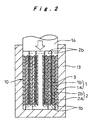
- This electrode plate group 10 is inserted and arranged in position in a molding jig 13 of cylindrical enclosure shape as shown in Figure 2, and is subjected to pressure by a pressing member 14 from one end aperture of the molding jig 13. Thereby, the projected portions of the current collectors 1b, 2b are elastically deformed to be bent radially inwards substantially at 90° as shown by the phantom lines, whereby flat planes 11, 12 are formed at opposite ends of the electrode plate group.
- the projected portions of the current collectors 1b, 2b are not bent radially outwards. Rather, all of the projected portions of the current collectors are uniformly and progressively bent radially inwards. As a result, although folding may occur to some extent, they are as a whole deformed together into flat planes 11, 12.
- the electrode plate group 10 formed with flat planes 11, 12 is removed from the molding jig 13 and, as shown in Figure 3, the current collecting plates 8, 9 are pressed into contact with the flat planes 11, 12, and these are laser welded together by irradiating a plurality of locations in the circumferential direction of the surfaces of the current collecting plates 8, 9 with a laser beam 15 in radial fashion from the middle towards the outer periphery.
- the electrode plate group 10 with these current collecting plates 8, 9 joined thereto is accommodated within the battery case 5 and vacuum-impregnated with the electrolyte.
- the current collecting plates 8, 9 are connected by laser welding etc to the battery closure 6 and the battery case 5, respectively, and the battery case 5 is sealed with the battery closure 6.
- the electrode plate group 10 in this lithium ion rechargeable battery is constituted by winding in spiral fashion a positive electrode plate 1 and a negative electrode plate 2 with a separator 3 therebetween, such that the current collectors 1b, 2b of the two electrode plates respectively project at opposite ends thereof and the current collecting plates 8, 9 are joined to the flat planes 11, 12 formed by the projected portions of the current collectors 1b, 2b. Accordingly, the efficiency of current collection is high and the rise in temperature during charging/discharging can be kept small. Furthermore, since the flat planes 11, 12 are formed by the current collectors 1b, 2b themselves, the construction can be made of low cost. Furthermore, the construction is stable with respect to vibration etc, because these flat planes 11, 12 are welded to the current collecting plates 8, 9, so charging and discharging can be effected in a stable fashion.
- the flat planes 11, 12 for joining the current collecting plates 8, 9 are formed by applying pressure to both ends of the electrode plate group 10 in the direction along the core of the winding axis, they can be formed efficiently.
- the current collecting plates 8, 9 are pressed towards the flat planes 11, 12 and subjected to laser welding in the radial direction at a plurality of locations in the circumferential direction in this tightly pressed condition. Therefore, integral welding of a large number of locations of the side edges of the current collectors 1b, 2b to the current collecting plates 8, 9 can be achieved in a straightforward fashion, enabling high current collection efficiency to be achieved with ease of operation.
- Figure 4 illustrates a modified example of a current collecting plate 8 or 9, in which a plurality of ribs 16 are formed projecting towards the projected portions of the current collectors 1b, 2b of the electrode plate group 10 in radial fashion. Laser welding is effected along these ribs 16 under a condition in which the current collecting plates 8, 9 are pressed toward the electrode plate group 10 such that these ribs 16 bite into the projected portions of the current collectors 1b, 2b so as to form the flat planes 11, 12.
- the current collector of one or other of the electrodes projects on at least one side of the electrode plate group, a flat plane being formed at the tip of this projected portion by itself, and a current collector plate is welded to this projected portion of the current collector. Accordingly, the current collection efficiency is high and the rise in temperature during charging/discharging can be made small. Since the flat plane is formed by the current collector itself, an inexpensive construction can be achieved, and since the current collecting plate is joined to the flat plane, the construction is stable with regard to vibration etc. The present invention thereby realizes an inexpensive structure for electrode plate group with which the battery exhibits excellent current collection efficiency and stable charging/discharging characteristics.
Landscapes
- Chemical & Material Sciences (AREA)
- Chemical Kinetics & Catalysis (AREA)
- Electrochemistry (AREA)
- General Chemical & Material Sciences (AREA)
- Secondary Cells (AREA)
- Connection Of Batteries Or Terminals (AREA)
- Cell Electrode Carriers And Collectors (AREA)
- Battery Electrode And Active Subsutance (AREA)
Applications Claiming Priority (3)
| Application Number | Priority Date | Filing Date | Title |
|---|---|---|---|
| JP10075099A JP4866496B2 (ja) | 1999-04-08 | 1999-04-08 | 二次電池の製造方法 |
| JP10075099 | 1999-04-08 | ||
| PCT/JP2000/002304 WO2000062356A1 (fr) | 1999-04-08 | 2000-04-07 | Batterie auxiliaire |
Publications (2)
| Publication Number | Publication Date |
|---|---|
| EP1102337A1 true EP1102337A1 (fr) | 2001-05-23 |
| EP1102337A4 EP1102337A4 (fr) | 2004-09-22 |
Family
ID=14282214
Family Applications (1)
| Application Number | Title | Priority Date | Filing Date |
|---|---|---|---|
| EP00915443A Withdrawn EP1102337A4 (fr) | 1999-04-08 | 2000-04-07 | Batterie auxiliaire |
Country Status (4)
| Country | Link |
|---|---|
| US (2) | US6818025B1 (fr) |
| EP (1) | EP1102337A4 (fr) |
| JP (1) | JP4866496B2 (fr) |
| WO (1) | WO2000062356A1 (fr) |
Cited By (13)
| Publication number | Priority date | Publication date | Assignee | Title |
|---|---|---|---|---|
| FR2853764A1 (fr) * | 2003-04-11 | 2004-10-15 | Cit Alcatel | Raccordement electrique d'une connexion a un faisceau electrochimique |
| EP1255310A3 (fr) * | 2001-05-02 | 2004-11-24 | Ngk Insulators, Ltd. | Pile secondaire au lithium |
| EP1484808A1 (fr) * | 2002-03-13 | 2004-12-08 | Sanyo Electric Co., Ltd. | Batterie auxiliaire |
| EP1601034A2 (fr) * | 2004-05-28 | 2005-11-30 | M&G Eco Battery Institute Co. Ltd. | Générateur électrochimique secondaire |
| EP1995805A1 (fr) * | 2007-05-22 | 2008-11-26 | Hitachi Vehicle Energy, Ltd. | Batterie secondaire au lithium-ion |
| EP2093820A1 (fr) | 2008-02-22 | 2009-08-26 | Saft Groupe S.A. | Connection électrique pour accumulateur de courant |
| WO2015044820A1 (fr) | 2013-09-25 | 2015-04-02 | Commissariat A L'energie Atomique Et Aux Energies Alternatives | Procédé de réalisation d'un faisceau électrochimique d'un accumulateur au lithium |
| FR3030118A1 (fr) * | 2014-12-15 | 2016-06-17 | Saft Groupe Sa | Procede de connexion dans un accumulateur et accumulateur ainsi connecte |
| FR3037724A1 (fr) * | 2015-06-22 | 2016-12-23 | Commissariat Energie Atomique | Procede de realisation d'un faisceau electrochimique d'accumulateur au lithium avec pliage ou enroulement des extremites de feuillard sur elles-memes |
| WO2016207151A1 (fr) | 2015-06-22 | 2016-12-29 | Commissariat A L'energie Atomique Et Aux Energies Alternatives | Procede de realisation d'un faisceau electrochimique d'accumulateur metal-ion avec mousse metallique aux extremites de feuillards |
| EP3258519A1 (fr) * | 2016-06-16 | 2017-12-20 | VARTA Microbattery GmbH | Cellule electrochimique a resistance interne optimisee |
| WO2017216021A1 (fr) | 2016-06-15 | 2017-12-21 | Commissariat A L'energie Atomique Et Aux Energies Alternatives | Electrode pour faisceau electrochimique d'un accumulateur metal-ion ou d'un supercondensateur, procede de realisation du faisceau et de l'accumulateur associes |
| EP2618350A4 (fr) * | 2010-09-16 | 2018-03-14 | Shin-Kobe Electric Machinery Co., Ltd. | Procédé pour produire une unité groupe de plaques électrodes pour condensateur au lithium-ion, et condensateur au lithium-ion |
Families Citing this family (48)
| Publication number | Priority date | Publication date | Assignee | Title |
|---|---|---|---|---|
| JP2000323117A (ja) * | 1999-05-14 | 2000-11-24 | Sanyo Electric Co Ltd | 円筒型蓄電池 |
| JP4168227B2 (ja) * | 2001-03-02 | 2008-10-22 | トヨタ自動車株式会社 | 電池およびその製造方法 |
| JP3845283B2 (ja) * | 2001-09-11 | 2006-11-15 | 本田技研工業株式会社 | 円筒型電気二重層キャパシタにおける電極巻回体と集電板とのレーザ溶接用治具 |
| WO2003036740A1 (fr) | 2001-10-19 | 2003-05-01 | Matsushita Electric Industrial Co., Ltd. | Accumulateur secondaire |
| JP3960877B2 (ja) * | 2002-08-05 | 2007-08-15 | 三洋電機株式会社 | 電池の製造方法 |
| JP4524982B2 (ja) * | 2002-10-16 | 2010-08-18 | パナソニック株式会社 | 円筒型二次電池 |
| JP4318905B2 (ja) * | 2002-11-08 | 2009-08-26 | 日本碍子株式会社 | リチウム二次電池 |
| JP4594590B2 (ja) | 2002-12-27 | 2010-12-08 | パナソニック株式会社 | 電気化学素子 |
| CN100356615C (zh) | 2002-12-27 | 2007-12-19 | 松下电器产业株式会社 | 电化学元件 |
| JP4472259B2 (ja) | 2002-12-27 | 2010-06-02 | パナソニック株式会社 | 電気化学素子 |
| KR100578800B1 (ko) * | 2004-02-16 | 2006-05-11 | 삼성에스디아이 주식회사 | 이차 전지 |
| JP4798967B2 (ja) * | 2004-06-14 | 2011-10-19 | パナソニック株式会社 | 電気化学素子 |
| JP5032737B2 (ja) | 2004-06-14 | 2012-09-26 | パナソニック株式会社 | 電気化学素子 |
| KR20050121914A (ko) * | 2004-06-23 | 2005-12-28 | 삼성에스디아이 주식회사 | 이차 전지와 이에 사용되는 전극 조립체 |
| WO2007028152A2 (fr) | 2005-09-02 | 2007-03-08 | A123 Systems, Inc. | Conception d'element de batterie et procede de construction de celle-ci |
| US8084158B2 (en) * | 2005-09-02 | 2011-12-27 | A123 Systems, Inc. | Battery tab location design and method of construction |
| JP5082256B2 (ja) * | 2006-02-23 | 2012-11-28 | パナソニック株式会社 | 密閉型蓄電池 |
| KR20090012262A (ko) * | 2006-05-09 | 2009-02-02 | 발렌스 테크놀로지, 인코포레이티드 | 증가된 집전 효율을 갖는 2차 전기화학 전지 |
| WO2008035495A1 (fr) | 2006-09-20 | 2008-03-27 | Panasonic Corporation | Pile secondaire et procédé pour fabriquer une pile secondaire |
| KR20090108633A (ko) | 2007-03-15 | 2009-10-15 | 파나소닉 주식회사 | 이차 전지 및 이차 전지의 제조 방법 |
| US8236441B2 (en) | 2007-07-24 | 2012-08-07 | A123 Systems, Inc. | Battery cell design and methods of its construction |
| CN100517852C (zh) * | 2007-08-21 | 2009-07-22 | 中国科学院上海微系统与信息技术研究所 | 一种卷绕式锂离子电池及其制作方法 |
| JP2011505671A (ja) * | 2007-11-30 | 2011-02-24 | エイ 123 システムズ,インク. | 非対称な端子を有する電池セルデザイン |
| JP5166511B2 (ja) * | 2008-03-07 | 2013-03-21 | パナソニック株式会社 | リチウムイオン二次電池およびその製造方法 |
| JP2011170972A (ja) * | 2008-06-17 | 2011-09-01 | Panasonic Corp | 二次電池の製造方法 |
| KR20110042039A (ko) * | 2008-08-25 | 2011-04-22 | 파나소닉 주식회사 | 이차전지의 제조방법 및 이차전지 |
| EP2394324B1 (fr) | 2009-02-09 | 2015-06-10 | VARTA Microbattery GmbH | Piles-boutons et leur procédé de fabrication |
| KR101023865B1 (ko) * | 2009-02-25 | 2011-03-22 | 에스비리모티브 주식회사 | 이차 전지 |
| KR101147171B1 (ko) * | 2009-04-21 | 2012-05-25 | 에스비리모티브 주식회사 | 이차 전지 |
| JP2010257851A (ja) * | 2009-04-27 | 2010-11-11 | Toyota Motor Corp | 電池の製造方法 |
| DE102009060800A1 (de) | 2009-06-18 | 2011-06-09 | Varta Microbattery Gmbh | Knopfzelle mit Wickelelektrode und Verfahren zu ihrer Herstellung |
| CN102197518A (zh) * | 2009-08-07 | 2011-09-21 | 松下电器产业株式会社 | 非水电解质二次电池及其制造方法 |
| JP2012104621A (ja) * | 2010-11-09 | 2012-05-31 | Nippon Chemicon Corp | コンデンサ及びその製造方法 |
| JP2012104620A (ja) * | 2010-11-09 | 2012-05-31 | Nippon Chemicon Corp | コンデンサ及びその製造方法 |
| CN103210459B (zh) | 2010-11-09 | 2016-08-10 | 日本贵弥功株式会社 | 电容器及其制造方法 |
| JP2012160658A (ja) * | 2011-02-02 | 2012-08-23 | Nippon Chemicon Corp | コンデンサの製造方法 |
| EP2728647B1 (fr) | 2011-06-28 | 2018-10-10 | Nippon Chemi-Con Corporation | Batterie et son procédé de fabrication |
| DE102012217478A1 (de) * | 2012-09-26 | 2014-03-27 | Robert Bosch Gmbh | Batteriezelle mit Stromabnehmer zur Gehäusekontaktierung |
| JP6201795B2 (ja) | 2014-02-10 | 2017-09-27 | トヨタ自動車株式会社 | 蓄電装置の製造方法 |
| JP2019504445A (ja) | 2015-12-18 | 2019-02-14 | ローベルト ボツシユ ゲゼルシヤフト ミツト ベシユレンクテル ハフツングRobert Bosch Gmbh | パウチセル用の壁貫通型集電装置 |
| US9780381B2 (en) | 2016-01-21 | 2017-10-03 | Bosch Battery Systems, Llc | Current collectors |
| US10490842B2 (en) * | 2016-05-12 | 2019-11-26 | Bosch Battery Systems Llc | Prismatic electrochemical cell having an improved electrical connection between the electrode assembly and the terminal |
| US10193109B2 (en) | 2016-05-12 | 2019-01-29 | Bosch Battery Systems Llc | Prismatic electrochemical cell |
| US10115997B2 (en) | 2016-05-12 | 2018-10-30 | Bosch Battery Systems Llc | Prismatic electrochemical cell |
| EP3806217A1 (fr) * | 2019-10-11 | 2021-04-14 | VARTA Microbattery GmbH | Élément d'accumulateur d'énergie et procédé de fabrication |
| CN114982019A (zh) * | 2020-01-23 | 2022-08-30 | 株式会社村田制作所 | 二次电池、电子设备以及电动工具 |
| CN112993491A (zh) * | 2021-02-05 | 2021-06-18 | 刘昌国 | 一种锂电池、电芯及装配方法 |
| KR102601767B1 (ko) | 2022-08-31 | 2023-11-13 | 주식회사 오씨모바일 | 탭리스 전극을 가진 이차전지, 이차전지 팩 및 그 제조방법 |
Citations (3)
| Publication number | Priority date | Publication date | Assignee | Title |
|---|---|---|---|---|
| DE2127823A1 (de) * | 1970-06-23 | 1971-12-30 | Accumulateurs Fixes | Elektrochemisches Element, insbesondere fur Hochleistungs-Entladebetriebe |
| JPS6072160A (ja) * | 1983-09-29 | 1985-04-24 | Shin Kobe Electric Mach Co Ltd | Ni―Cd電池 |
| US5047300A (en) * | 1989-06-14 | 1991-09-10 | Bolder Battery, Inc. | Ultra-thin plate electrochemical cell |
Family Cites Families (13)
| Publication number | Priority date | Publication date | Assignee | Title |
|---|---|---|---|---|
| FR2097301A5 (fr) * | 1970-07-01 | 1972-03-03 | Accumulateurs Fixes | |
| JPS55113261A (en) * | 1979-02-22 | 1980-09-01 | Yuasa Battery Co Ltd | Enclosed type alkali cell |
| JPS606073B2 (ja) * | 1979-11-07 | 1985-02-15 | 松下電器産業株式会社 | 渦巻電極体を備えた電池の製造法 |
| JPS6065452A (ja) * | 1983-09-20 | 1985-04-15 | Sanyo Electric Co Ltd | アルカリ蓄電池 |
| JPH04301360A (ja) * | 1991-03-28 | 1992-10-23 | Sanyo Electric Co Ltd | 電極板に集電板を接続する電池の製造方法 |
| US5290414A (en) * | 1992-05-15 | 1994-03-01 | Eveready Battery Company, Inc. | Separator/electrolyte combination for a nonaqueous cell |
| JPH0714569A (ja) * | 1993-06-24 | 1995-01-17 | Yuasa Corp | 集電端子およびこれを用いた蓄電池の製造方法 |
| JPH08115744A (ja) | 1994-10-19 | 1996-05-07 | Sony Corp | 円筒型非水電解液二次電池及びその製造方法 |
| WO1997030487A1 (fr) * | 1996-02-16 | 1997-08-21 | Fuji Photo Film Co., Ltd. | Batterie secondaire non aqueuse |
| JP3363708B2 (ja) | 1996-06-27 | 2003-01-08 | 三洋電機株式会社 | 二次電池 |
| US5972532A (en) | 1998-05-04 | 1999-10-26 | Saft America, Inc. | Current collection through the ends of a spirally wound electrochemical cell |
| JP2000021436A (ja) * | 1998-07-03 | 2000-01-21 | Denso Corp | 円筒型電池 |
| JP3501656B2 (ja) | 1998-08-07 | 2004-03-02 | 本田技研工業株式会社 | 蓄電素子 |
-
1999
- 1999-04-08 JP JP10075099A patent/JP4866496B2/ja not_active Expired - Fee Related
-
2000
- 2000-04-07 EP EP00915443A patent/EP1102337A4/fr not_active Withdrawn
- 2000-04-07 US US09/719,323 patent/US6818025B1/en not_active Expired - Lifetime
- 2000-04-07 WO PCT/JP2000/002304 patent/WO2000062356A1/fr active Application Filing
-
2004
- 2004-06-28 US US10/878,888 patent/US7014666B2/en not_active Expired - Fee Related
Patent Citations (3)
| Publication number | Priority date | Publication date | Assignee | Title |
|---|---|---|---|---|
| DE2127823A1 (de) * | 1970-06-23 | 1971-12-30 | Accumulateurs Fixes | Elektrochemisches Element, insbesondere fur Hochleistungs-Entladebetriebe |
| JPS6072160A (ja) * | 1983-09-29 | 1985-04-24 | Shin Kobe Electric Mach Co Ltd | Ni―Cd電池 |
| US5047300A (en) * | 1989-06-14 | 1991-09-10 | Bolder Battery, Inc. | Ultra-thin plate electrochemical cell |
Non-Patent Citations (2)
| Title |
|---|
| PATENT ABSTRACTS OF JAPAN vol. 0092, no. 08 (E-338), 24 August 1985 (1985-08-24) & JP 60 072160 A (SHINKOUBE DENKI KK), 24 April 1985 (1985-04-24) * |
| See also references of WO0062356A1 * |
Cited By (28)
| Publication number | Priority date | Publication date | Assignee | Title |
|---|---|---|---|---|
| EP1255310A3 (fr) * | 2001-05-02 | 2004-11-24 | Ngk Insulators, Ltd. | Pile secondaire au lithium |
| US7214250B2 (en) | 2001-05-02 | 2007-05-08 | Ngk Insulators, Ltd. | Lithium secondary cell |
| EP1484808A4 (fr) * | 2002-03-13 | 2006-05-17 | Sanyo Electric Co | Batterie auxiliaire |
| EP1484808A1 (fr) * | 2002-03-13 | 2004-12-08 | Sanyo Electric Co., Ltd. | Batterie auxiliaire |
| US7273678B2 (en) | 2002-03-13 | 2007-09-25 | Sanyo Electric Co., Ltd. | Secondary cell |
| US8007549B2 (en) | 2003-04-11 | 2011-08-30 | Saft Groupe Sa | Electric coupling of a connection to an electrochemical bundle |
| EP1596449A2 (fr) * | 2003-04-11 | 2005-11-16 | Saft, Sa | Raccordement électrique à un faisceau de connexion pour électrodes |
| FR2853764A1 (fr) * | 2003-04-11 | 2004-10-15 | Cit Alcatel | Raccordement electrique d'une connexion a un faisceau electrochimique |
| EP1596449A3 (fr) * | 2003-04-11 | 2007-04-11 | Saft, Sa | Raccordement électrique à un faisceau de connexion pour électrodes |
| EP1601034A2 (fr) * | 2004-05-28 | 2005-11-30 | M&G Eco Battery Institute Co. Ltd. | Générateur électrochimique secondaire |
| EP1601034A3 (fr) * | 2004-05-28 | 2007-07-25 | M&G Eco Battery Institute Co. Ltd. | Générateur électrochimique secondaire |
| US7758997B2 (en) | 2004-05-28 | 2010-07-20 | M&G Eco-Battery Institute Co., Ltd. | Secondary battery |
| EP1995805A1 (fr) * | 2007-05-22 | 2008-11-26 | Hitachi Vehicle Energy, Ltd. | Batterie secondaire au lithium-ion |
| CN101312236B (zh) * | 2007-05-22 | 2010-12-01 | 日立车辆能源株式会社 | 锂离子二次电池 |
| US8053105B2 (en) | 2007-05-22 | 2011-11-08 | Hitachi Vehicle Energy, Ltd. | Lithium-ion secondary battery |
| EP2093820A1 (fr) | 2008-02-22 | 2009-08-26 | Saft Groupe S.A. | Connection électrique pour accumulateur de courant |
| EP2618350A4 (fr) * | 2010-09-16 | 2018-03-14 | Shin-Kobe Electric Machinery Co., Ltd. | Procédé pour produire une unité groupe de plaques électrodes pour condensateur au lithium-ion, et condensateur au lithium-ion |
| WO2015044820A1 (fr) | 2013-09-25 | 2015-04-02 | Commissariat A L'energie Atomique Et Aux Energies Alternatives | Procédé de réalisation d'un faisceau électrochimique d'un accumulateur au lithium |
| EP3035411A1 (fr) | 2014-12-15 | 2016-06-22 | Saft Groupe S.A. | Procede de connexion dans un accumulateur et accumulateur ainsi connecte |
| FR3030118A1 (fr) * | 2014-12-15 | 2016-06-17 | Saft Groupe Sa | Procede de connexion dans un accumulateur et accumulateur ainsi connecte |
| US10062893B2 (en) | 2014-12-15 | 2018-08-28 | Saft Groupe Sa | Connection method in an accumulator and accumulator thus connected |
| FR3037724A1 (fr) * | 2015-06-22 | 2016-12-23 | Commissariat Energie Atomique | Procede de realisation d'un faisceau electrochimique d'accumulateur au lithium avec pliage ou enroulement des extremites de feuillard sur elles-memes |
| WO2016207154A1 (fr) | 2015-06-22 | 2016-12-29 | Commissariat A L'energie Atomique Et Aux Energies Alternatives | Procede de realisation d'un faisceau electrochimique d'accumulateur metal-ion avec pliage ou enroulement des extremites de feuillard sur elles-memes |
| WO2016207151A1 (fr) | 2015-06-22 | 2016-12-29 | Commissariat A L'energie Atomique Et Aux Energies Alternatives | Procede de realisation d'un faisceau electrochimique d'accumulateur metal-ion avec mousse metallique aux extremites de feuillards |
| US10516150B2 (en) | 2015-06-22 | 2019-12-24 | Commissariat A L'energie Atomique Et Aux Energies Alternatives | Method for producing an electrochemical bundle for a metal-ion accumulator comprising folding or coiling the foil ends around themselves |
| WO2017216021A1 (fr) | 2016-06-15 | 2017-12-21 | Commissariat A L'energie Atomique Et Aux Energies Alternatives | Electrode pour faisceau electrochimique d'un accumulateur metal-ion ou d'un supercondensateur, procede de realisation du faisceau et de l'accumulateur associes |
| EP3258519A1 (fr) * | 2016-06-16 | 2017-12-20 | VARTA Microbattery GmbH | Cellule electrochimique a resistance interne optimisee |
| WO2017215900A1 (fr) * | 2016-06-16 | 2017-12-21 | Varta Microbattery Gmbh | Cellule électrochimique à résistance intérieure optimisée |
Also Published As
| Publication number | Publication date |
|---|---|
| EP1102337A4 (fr) | 2004-09-22 |
| US20040237290A1 (en) | 2004-12-02 |
| JP2000294222A (ja) | 2000-10-20 |
| US6818025B1 (en) | 2004-11-16 |
| US7014666B2 (en) | 2006-03-21 |
| JP4866496B2 (ja) | 2012-02-01 |
| WO2000062356A1 (fr) | 2000-10-19 |
Similar Documents
| Publication | Publication Date | Title |
|---|---|---|
| US6818025B1 (en) | Rechargeable battery having a current collector integrally formed and contacting a current collector plate to form a flat plane | |
| CN102646844B (zh) | 二次电池 | |
| JP2019192646A (ja) | 電池及び電池パック | |
| US9520588B2 (en) | Nonaqueous electrolyte secondary cell | |
| JP2003308842A (ja) | 非水電解液リチウム二次電池 | |
| JP2003007346A (ja) | リチウム二次電池及びその製造方法 | |
| JP2017103091A (ja) | リチウムイオン二次電池 | |
| CN111480250B (zh) | 锂离子二次电池用正极和使用它的锂离子二次电池 | |
| EP1191618B1 (fr) | Batterie rechargeable avec electrolyte non aqueuse | |
| JP5755870B2 (ja) | 二次電池用正極電極、二次電池、および二次電池用正極電極の製造方法 | |
| JP2002222666A (ja) | リチウム二次電池 | |
| JP2007073437A (ja) | 二次電池 | |
| JP4649698B2 (ja) | 二次電池 | |
| JP4811983B2 (ja) | 捲回電極およびその製造方法、並びにそれを用いた電池 | |
| JP4420484B2 (ja) | 密閉型電池 | |
| JP2001185220A (ja) | 円筒形リチウムイオン電池 | |
| US20040197652A1 (en) | Nonaqueous electrolyte rechargeable battery | |
| JP5254910B2 (ja) | リチウムイオン二次電池 | |
| JPH09306443A (ja) | 非水電解液電池 | |
| JP2000294202A (ja) | 薄型電池 | |
| JP4019700B2 (ja) | 二次電池 | |
| JP7365562B2 (ja) | 二次電池の捲回電極体 | |
| JP3709965B2 (ja) | 円筒形リチウムイオン電池 | |
| JP4576891B2 (ja) | 非水電解質二次電池 | |
| JP2001256931A (ja) | 電池、電池容器、電池容器材、及び電池容器の製造方法 |
Legal Events
| Date | Code | Title | Description |
|---|---|---|---|
| PUAI | Public reference made under article 153(3) epc to a published international application that has entered the european phase |
Free format text: ORIGINAL CODE: 0009012 |
|
| 17P | Request for examination filed |
Effective date: 20001227 |
|
| AK | Designated contracting states |
Kind code of ref document: A1 Designated state(s): AT BE CH CY DE DK ES FI FR GB GR IE IT LI LU MC NL PT SE |
|
| RBV | Designated contracting states (corrected) |
Designated state(s): DE FR GB |
|
| A4 | Supplementary search report drawn up and despatched |
Effective date: 20040809 |
|
| RIC1 | Information provided on ipc code assigned before grant |
Ipc: 7H 01M 2/26 A |
|
| RAP1 | Party data changed (applicant data changed or rights of an application transferred) |
Owner name: PANASONIC CORPORATION |
|
| 17Q | First examination report despatched |
Effective date: 20100302 |
|
| GRAP | Despatch of communication of intention to grant a patent |
Free format text: ORIGINAL CODE: EPIDOSNIGR1 |
|
| STAA | Information on the status of an ep patent application or granted ep patent |
Free format text: STATUS: THE APPLICATION IS DEEMED TO BE WITHDRAWN |
|
| 18D | Application deemed to be withdrawn |
Effective date: 20130803 |