EP1089231A2 - Dispositif pour la reconnaissance des lignes de marquage routières - Google Patents
Dispositif pour la reconnaissance des lignes de marquage routières Download PDFInfo
- Publication number
- EP1089231A2 EP1089231A2 EP00308351A EP00308351A EP1089231A2 EP 1089231 A2 EP1089231 A2 EP 1089231A2 EP 00308351 A EP00308351 A EP 00308351A EP 00308351 A EP00308351 A EP 00308351A EP 1089231 A2 EP1089231 A2 EP 1089231A2
- Authority
- EP
- European Patent Office
- Prior art keywords
- lane
- image
- road
- marker
- recognition apparatus
- Prior art date
- Legal status (The legal status is an assumption and is not a legal conclusion. Google has not performed a legal analysis and makes no representation as to the accuracy of the status listed.)
- Withdrawn
Links
Images


Classifications
-
- G—PHYSICS
- G06—COMPUTING; CALCULATING OR COUNTING
- G06T—IMAGE DATA PROCESSING OR GENERATION, IN GENERAL
- G06T7/00—Image analysis
- G06T7/50—Depth or shape recovery
- G06T7/55—Depth or shape recovery from multiple images
- G06T7/593—Depth or shape recovery from multiple images from stereo images
-
- G—PHYSICS
- G01—MEASURING; TESTING
- G01S—RADIO DIRECTION-FINDING; RADIO NAVIGATION; DETERMINING DISTANCE OR VELOCITY BY USE OF RADIO WAVES; LOCATING OR PRESENCE-DETECTING BY USE OF THE REFLECTION OR RERADIATION OF RADIO WAVES; ANALOGOUS ARRANGEMENTS USING OTHER WAVES
- G01S11/00—Systems for determining distance or velocity not using reflection or reradiation
- G01S11/12—Systems for determining distance or velocity not using reflection or reradiation using electromagnetic waves other than radio waves
-
- G—PHYSICS
- G06—COMPUTING; CALCULATING OR COUNTING
- G06V—IMAGE OR VIDEO RECOGNITION OR UNDERSTANDING
- G06V10/00—Arrangements for image or video recognition or understanding
- G06V10/40—Extraction of image or video features
- G06V10/44—Local feature extraction by analysis of parts of the pattern, e.g. by detecting edges, contours, loops, corners, strokes or intersections; Connectivity analysis, e.g. of connected components
- G06V10/457—Local feature extraction by analysis of parts of the pattern, e.g. by detecting edges, contours, loops, corners, strokes or intersections; Connectivity analysis, e.g. of connected components by analysing connectivity, e.g. edge linking, connected component analysis or slices
-
- G—PHYSICS
- G06—COMPUTING; CALCULATING OR COUNTING
- G06V—IMAGE OR VIDEO RECOGNITION OR UNDERSTANDING
- G06V20/00—Scenes; Scene-specific elements
- G06V20/50—Context or environment of the image
- G06V20/56—Context or environment of the image exterior to a vehicle by using sensors mounted on the vehicle
- G06V20/588—Recognition of the road, e.g. of lane markings; Recognition of the vehicle driving pattern in relation to the road
-
- H—ELECTRICITY
- H04—ELECTRIC COMMUNICATION TECHNIQUE
- H04N—PICTORIAL COMMUNICATION, e.g. TELEVISION
- H04N13/00—Stereoscopic video systems; Multi-view video systems; Details thereof
- H04N13/20—Image signal generators
- H04N13/204—Image signal generators using stereoscopic image cameras
- H04N13/239—Image signal generators using stereoscopic image cameras using two 2D image sensors having a relative position equal to or related to the interocular distance
-
- B—PERFORMING OPERATIONS; TRANSPORTING
- B60—VEHICLES IN GENERAL
- B60T—VEHICLE BRAKE CONTROL SYSTEMS OR PARTS THEREOF; BRAKE CONTROL SYSTEMS OR PARTS THEREOF, IN GENERAL; ARRANGEMENT OF BRAKING ELEMENTS ON VEHICLES IN GENERAL; PORTABLE DEVICES FOR PREVENTING UNWANTED MOVEMENT OF VEHICLES; VEHICLE MODIFICATIONS TO FACILITATE COOLING OF BRAKES
- B60T2210/00—Detection or estimation of road or environment conditions; Detection or estimation of road shapes
- B60T2210/20—Road shapes
- B60T2210/22—Banked curves
-
- G—PHYSICS
- G01—MEASURING; TESTING
- G01C—MEASURING DISTANCES, LEVELS OR BEARINGS; SURVEYING; NAVIGATION; GYROSCOPIC INSTRUMENTS; PHOTOGRAMMETRY OR VIDEOGRAMMETRY
- G01C21/00—Navigation; Navigational instruments not provided for in groups G01C1/00 - G01C19/00
- G01C21/26—Navigation; Navigational instruments not provided for in groups G01C1/00 - G01C19/00 specially adapted for navigation in a road network
- G01C21/34—Route searching; Route guidance
- G01C21/36—Input/output arrangements for on-board computers
- G01C21/3602—Input other than that of destination using image analysis, e.g. detection of road signs, lanes, buildings, real preceding vehicles using a camera
-
- G—PHYSICS
- G06—COMPUTING; CALCULATING OR COUNTING
- G06T—IMAGE DATA PROCESSING OR GENERATION, IN GENERAL
- G06T2207/00—Indexing scheme for image analysis or image enhancement
- G06T2207/10—Image acquisition modality
- G06T2207/10004—Still image; Photographic image
- G06T2207/10012—Stereo images
-
- H—ELECTRICITY
- H04—ELECTRIC COMMUNICATION TECHNIQUE
- H04N—PICTORIAL COMMUNICATION, e.g. TELEVISION
- H04N13/00—Stereoscopic video systems; Multi-view video systems; Details thereof
- H04N13/10—Processing, recording or transmission of stereoscopic or multi-view image signals
- H04N13/106—Processing image signals
- H04N13/133—Equalising the characteristics of different image components, e.g. their average brightness or colour balance
-
- H—ELECTRICITY
- H04—ELECTRIC COMMUNICATION TECHNIQUE
- H04N—PICTORIAL COMMUNICATION, e.g. TELEVISION
- H04N13/00—Stereoscopic video systems; Multi-view video systems; Details thereof
- H04N13/10—Processing, recording or transmission of stereoscopic or multi-view image signals
- H04N13/189—Recording image signals; Reproducing recorded image signals
-
- H—ELECTRICITY
- H04—ELECTRIC COMMUNICATION TECHNIQUE
- H04N—PICTORIAL COMMUNICATION, e.g. TELEVISION
- H04N13/00—Stereoscopic video systems; Multi-view video systems; Details thereof
- H04N13/20—Image signal generators
- H04N13/204—Image signal generators using stereoscopic image cameras
- H04N13/25—Image signal generators using stereoscopic image cameras using two or more image sensors with different characteristics other than in their location or field of view, e.g. having different resolutions or colour pickup characteristics; using image signals from one sensor to control the characteristics of another sensor
-
- H—ELECTRICITY
- H04—ELECTRIC COMMUNICATION TECHNIQUE
- H04N—PICTORIAL COMMUNICATION, e.g. TELEVISION
- H04N13/00—Stereoscopic video systems; Multi-view video systems; Details thereof
- H04N13/20—Image signal generators
- H04N13/296—Synchronisation thereof; Control thereof
-
- H—ELECTRICITY
- H04—ELECTRIC COMMUNICATION TECHNIQUE
- H04N—PICTORIAL COMMUNICATION, e.g. TELEVISION
- H04N13/00—Stereoscopic video systems; Multi-view video systems; Details thereof
- H04N2013/0074—Stereoscopic image analysis
- H04N2013/0077—Colour aspects
-
- H—ELECTRICITY
- H04—ELECTRIC COMMUNICATION TECHNIQUE
- H04N—PICTORIAL COMMUNICATION, e.g. TELEVISION
- H04N13/00—Stereoscopic video systems; Multi-view video systems; Details thereof
- H04N2013/0074—Stereoscopic image analysis
- H04N2013/0081—Depth or disparity estimation from stereoscopic image signals
-
- H—ELECTRICITY
- H04—ELECTRIC COMMUNICATION TECHNIQUE
- H04N—PICTORIAL COMMUNICATION, e.g. TELEVISION
- H04N13/00—Stereoscopic video systems; Multi-view video systems; Details thereof
- H04N2013/0074—Stereoscopic image analysis
- H04N2013/0092—Image segmentation from stereoscopic image signals
-
- H—ELECTRICITY
- H04—ELECTRIC COMMUNICATION TECHNIQUE
- H04N—PICTORIAL COMMUNICATION, e.g. TELEVISION
- H04N13/00—Stereoscopic video systems; Multi-view video systems; Details thereof
- H04N2013/0074—Stereoscopic image analysis
- H04N2013/0096—Synchronisation or controlling aspects
Definitions
- the present invention relates to an apparatus for recognizing road configurations ahead of an own vehicle by identifying lane markers drawn on road surfaces.
- vehicle surroundings monitoring apparatus for recognizing road configurations in front of an own vehicle using a preview sensor such as monocular camera, stereoscopic camera and the like.
- a preview sensor such as monocular camera, stereoscopic camera and the like.
- the detection of lane markers is performed only based on information of two-dimensional picture image, that is, brightness of image.
- the picture image obtained from the monocular camera does not provide distance information to an object. Accordingly, there is a possibility that objects having a brightness characteristic similar to lane markers, such as pillars of preceding vehicles, guardrails and the like, are recognized as lane markers.
- Japanese Patent Application Laid-open No. Toku-Kai-Hei 5-265547 discloses a technology in which a distance image (distribution characteristic of distance in picture images) is calculated based on a parallax in stereo images and objects (preceding vehicles, road surfaces and the like) are recognized only from the distance image.
- the lane markers are recognized only based on the distance image obtained from the stereo images, there is a possibility that objects having the configuration similar to lane markers and the different brightness characteristic are recognized as lane markers, because only rough configurations of objects are obtained from the distance distribution built in the distance image.
- objects for example, are traces of tire slips, shades, patches and the like.
- a lane recognition apparatus for recognizing lane markers on a road surface based on a pair of stereo images of a scene in front of an own vehicle obtained from a stereoscopic camera, comprises a stereo image processing means fox calculating a distance information of an image based on the pair of the images, a lane detecting means for detecting a lane marker of a lane in the image based on a brightness information of the image and the distance information calculated by the stereo image processing means and a lane position recognition means for recognizing a position of the lane marker in real space based on a position of the lane marker detected by the lane detecting means and the distance information calculated by the stereo image processing means.
- numeral 1 denotes a stereoscopic camera for imaging the scenery ahead of an own vehicle.
- the stereoscopic camera 1 is installed in the vicinity of a room mirror and is constituted by a pair of cameras 2a, 2b incorporating image sensors such as CCD and the like therein.
- the cameras 2a, 2b are transversely mounted at a specified interval of distance (base line length).
- the camera 2a (right camera) is referred to as a main-camera for obtaining reference images and is mounted on the right side of the vehicle when viewed from a driver.
- the camera 2b left camera
- the camera 2b left camera
- a sub-camera for obtaining comparison images and is mounted on the left side of the vehicle when viewed from the driver.
- Analogue images outputted from the respective cameras 2a, 2b in a synchronous timing are converted into digital images having a specified number of graduations (for example, 256 graduations in the gray scale) by A/D converters 3, 4. Further, with respect to thus digitalized images, an image correcting section 5 performs a correction of brightness, a geometrical transformation of images and the like.
- reference image data composed of 512 pixels horizontally and 200 pixels vertically are generated from output signals of the main camera 2a and comparison image data having the same vertical length (200 pixels) as the reference image and a horizontal length larger than the reference image (640 pixels) are generated from output signals of the sub camera 2b.
- the reference image data and the comparison image data are stored in an image data memory 8.
- a stereo image processing section 6 calculates a parallax based on the reference image data and comparison image data. Since one parallax is calculated for every pixel block composed of 4 x 4 pixels, maximum 128 x SO pieces of parallaxes are calculated for one frame of the reference image. With respect to a certain pixel block (hereinafter, referred to as an object pixel block) in the reference image, an area having a brightness correlation with the object pixel block, that is, a correlation object is searched and identified in the comparison image. Hereinafter, this process is referred to as "stereo matching". As well known, the distance to an object projected in a stereo image is presented as a horizontal deviation amount between the reference image and comparison image.
- the search may be performed along a horizontal line (epi-polar line) having the same j coordinate value as the object pixel block in the reference image .
- the stereo image processing section 6 evaluates a correlation with the object pixel block for every pixel block of the comparison image while shifting one pixel by one pixel on the epi-polar line.
- the city block distance CB is a sum of the difference (absolute value) of brightness values p1ij and p2ij over entire pixel blocks. The correlation between both pixel blocks becomes larger as the difference is small.
- the city block distance CB is calculated for every pixel block existing on the epipolar line .
- the other pixel in the comparison image is judged to be a correlation object of the object pixel block.
- the deviation amount between the object pixel block and the identified correlation object is a parallax.
- the stereo image processing section 6 evaluates an existence or a non-existence of, horizontal brightness edges of the pixel block, a relationship between a maximum and minimum values of the city block distance CB calculated on the same epi-polar line and the like. Further, in order to raise the reliability of parallaxes, a filtering process is applied to the parallaxes based on the result of the evaluation. As a result of the filtering process, only parallaxes regarded as effective are outputted.
- a hardware construction for calculating the city block distance CB and the filtering process are described in detail in the Japanese Patent Application Laid-open No. Toku-Kai-Hei 5-114099. If necessary, the reference should be made to the disclosure. After those processes, the calculated effective parallax are stored in a distance memory 7.
- a micro-computer 9 or functionally, a road recognition section 10 recognizes road configurations (lane markers) ahead of the vehicle based on the reference image data (brightness information) stored in the image data memory 8 and the parallaxes stored in the distance memory 7.
- the road configurations can be identified by recognizing the configurations of left and right lane markers (white markers, no passing lines and the like) .
- the primary feature of the embodiment lies in this lane recognition and more detailed descriptions of the recognition method will be made hereinafter.
- a solid object recognition section 11 recognizes solid objects (preceding vehicles and the like) in front of the vehicle. In recognizing road configurations or solid objects, vehicle behavior information from a vehicle speed sensor (not shown) or a steering angle sensor (not shown) or navigation information from a navigation apparatus (not shown) are taken into consideration. Further, a processing section 12 arouses a driver's attention by a warning device 18 such as display, speaker and the like or, if necessary, controls miscellaneous control sections 13 through 17, in case where it is judged based on information from the recognition sections 10 and 11 that a warning is necessary. For example, sometimes an automatic transmission control section 13 is instructed to carry out a shift-down and sometimes an engine control section 17 is instructed to reduce engine power. Other appropriate vehicle controls may be instructed to an anti-lock brake system (ABS) control section 14, a traction control system (TCS) control section 15 or a vehicle behavior control section 16 for controlling torque distributions and rotation speeds of respective wheels.
- ABS anti-lock brake system
- TCS traction control system
- Fig. 2 is a flowchart showing steps for recognizing lane markers.
- the road recognition section 10 repeatedly carries out steps shown in this flowchart until one picture image is completed.
- the one picture-full data is referred to as "one frame”.
- the image in which lane markers are detected is referred to as "reference image” having an area size of 512 x 200 pixels.
- the reference image is referred to as just “image”.
- the lane detection is performed in the horizontal direction or in the vertical direction for every horizontal line, as illustrated in Fig. 4.
- a plurality of horizontal lines are established in the reference image from a detection starting line js to a detection ending line je. These starting and ending lines may be established fixedly or may be established variably according to the pitching condition of the own vehicle.
- the detection process in the vertical direction is performed from the near side to the far side, namely, from below to above in the image, basically for every horizontal line.
- the horizontal line is one pixel wide, however, it may be a plurality of pixels wide.
- the interval of sampling that is, the interval of the horizontal line may be established to gradually increase as the detection process goes downward of the image.
- the position of lane marker in an entire image is determined by combining the position of partial lane markers on respective horizontal lines. The reason why the detection in the vertical direction is performed in such an order as going from below to above is that short distance lane markers can be detected relatively easily and include numerous data concerning lane markers.
- the detection process in the horizontal direction is performed successively for every one pixel from the center of the image to left and right side, respectively, that is, the detection of left lane markers is performed from right to left and the one of right lane markers is performed from left to right.
- the inside of left and right lane markers is a road surface whose brightness condition is easy to be estimated and consequently there is a small possibility of detecting lane markers erroneously, compared to the detection in an inverse direction.
- normally miscellaneous objects such as gutters and the like are projected on the outside of the lane markers, it is not easy to estimate the brightness condition of all objects likely to exist at that area. Accordingly, if the detection is performed from the outside to inside of lane marker, there is a possibility that the erroneous detection of lane markers often happens and it takes time to perform a detection process.
- the road recognition section 10 proceeds initializing processes.
- the lane recognition is performed in a plurality of segments, respectively.
- the initializing processes at the step 1 include establishments of a segment for ending the lane detection, an arrangement for indicating what segment the respective horizontal lines belong to, a line for correcting a road height and the like.
- a step 2 the position of lane markers is detected in an image (reference image) of one frame. Since the lane detection is executed for every horizontal line in order, the position of lane markers is a point on the horizontal line (hereinafter, referred to as "lane point") and the lane point is detected.
- Fig. 3 is a flowchart showing detailed steps of lane detection processes.
- An initial value of a counter j indicating the vertical position of the horizontal line is set to 0.
- the routine ends. Since the horizontal line indicated by the counter j is an object of process, the horizontal line is referred to as "object line j".
- the horizontal line on which the lane detection is performed starts with a detection start line js and end with a detection end line je. Accordingly, with respect to horizontal lines below the detection start line is, the lane detection is not performed. Consequently, only the increment of the counter j is carried out at the step 29 until the counter j counts js.
- the pre horizontal line jpre is four consecutive horizontal lines (js-4, js-3, js-2 and js-1) located immediately below the detection start line js.
- a road surface brightness Aroad is detected before the start of the lane detection.
- the road surface brightness Aroad is, as shown in Fig. 5, calculated based on brightness within a left pre-detection range PRE1 and a right pre-detection range PRE2. respectively.
- the pre-detection ranges PRE1, PRE2 are constituted by four pre-horizontal lines jpre and a detection start line js and are established at an area except the central portion of the image.
- the left and right pre-detection ranges PRE1, PRE2 are fixedly established at an area where the lane markers are likely to be projected under normal driving conditions.
- a histogram of brightness is calculated in respective detection ranges PRE1, PRE2, letting a brightness value most frequently observed be a road surface brightness Aroad in the respective ranges, namely, in the area of left and right lane markers.
- the road surface brightness Aroad is used as a base value (base value of threshold value) in judging the left (or right) lane marker at a step 24.
- the road surface brightness Aroad varies according to camera angles or areas on a road surface, in order to raise the accuracy of lane detection, it is preferable to detect the road surface brightness Aroad independently for every object line. Specifically, the road surface brightness Aroad is calculated from five horizontal lines (one object line and four horizontal lines immediately therebelow). Accordingly, in order to detect lane markers of the detection start line js, brightness information of four horizontal lines immediately below the line js (these are not objects of lane detection) is needed.
- a road surface brightness Aroad is determined beforehand for the preparation of the lane detection in the detection start line js.
- the road surface brightness Aroad of the object line j is calculated based on brightness information of respective lines already detected and stored in RAM of the micro-computer 9. Therefore, after the object line reaches a detection start line js, the step 22 is not carried out and thereafter, the detection of road surface brightness Aroad for respective object lines j is performed at a step 24.
- a detection area Rj is established on the object line j.
- the detection area Rj specifies a range of lane detection on the object line j, being established individually for every horizontal line.
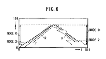
- Three establishment modes are prepared as follows in establishing the detection area Rj. The establishment mode is changed over according to the detecting situation of lane marker in the previous horizontal line. By selecting a most appropriate establishment mode for every horizontal line, it is possible to establish an area as narrow as possible and capable of surely detecting lane markers.
- Mode 0 A mode in which the position of lane marker (lane position) on the object line j is estimated based on the detection result of a previous horizontal line in a present frame and the detection area is established on the basis of the estimated lane position.
- Mode 1 A mode in which a narrow detection area is established using the result of recognition (lane position) in a previous frame.
- Mode 2 A mode in which a wide detection area is established using the result of recognition (lane position) in a previous frame.
- Fig. 6 is a diagram showing a detection area R established according to a mode.
- the mode is set to Mode 2 in the initial condition. Accordingly, a wide detection area Rjs is established on the detection start line js on the basis of a lane position detected in a previous frame. The lane detection is proceeded for each line in Mode 2. From the view point of reducing processing time and raising the accuracy of detection, it is necessary to establish an area as narrow as possible. Hence, the size (width) of the detection area Rj of the object line j is regulated based on "reliability of lane markers" detected in the previous frame.
- the reliability of lane markers is calculated at a step 5.
- the detection area is established based on this calculated reliability of lane markers.
- the specific method of evaluation of the reliability will be described in detail hereinafter. Describing roughly, the reliability of lane markers are determined taking a continuity of the lane position (position of lane marker) between frames and the number of data of the lane position.
- the width of the detection area Rj on each object line j is established to be smaller as the line j lies high in the image even with the same degree of reliability.
- the lane in the image becomes narrower as it is far.
- the width of the detection area R is established to be smaller as the detection area lies high (far) in the image. It is the same with in Mode 1.
- the detection area R is established in Mode 2 and when the lane marker is detected in a horizontal line lager than a specified number, the mode shifts to Mode 0.
- Mode 0 a narrowest detection area R among three modes is established.
- the result of detection before the horizontal line j-1 (line immediately below the object line) is used.
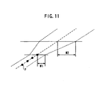
- Fig. 10 is a diagram for explaining the establishment of the detection area R in Mode 0 .
- a lane point P is detected on the horizontal line j-1 and a gradient a of the lane marker on the image plane (i-j plane) is calculated based on the lane marker already detected.
- a detection area Rj having a specified width is established on the basis of the temporary lane point Pj' in consideration of curves or detection errors.
- non-detectable line If such non-detectable lines appear consecutively after a narrow detection area R is established in Mode 0, there is a possibility that the detection area R is established in a position away from actual lane markers. Hence, as shown in Fig. 11, if no lane marker can be detected in an object line j and the number of non-detectable lines exceeds a specified value, the detection area R is gradually enlarged hereinafter. W1 shown in Fig.
- Mode 11 denotes an allowable minimum width of the detection area R which has been established when the lane point Ps are detected consecutively and W2 denotes an allowable maximum width of the detection area R. If a specified number of non-detectable lines appear consecutively even after the detection area R reaches the allowable maximum width W2, the mode shifts to Mode 1 in which the detection area R is established based on the lane position in the previous frame.
- a lane marker is detected within the detection area Rj established on the object line j. Further, a road surface brightness Aroad with respect to the object line j is also calculated at the step 24. If necessary, information calculated at the step 22 (pre-detection of road surface brightness) is used.
- the lane detection method according to this embodiment is characterized in using distance information of the image calculated in the stereo image processing section 6 besides brightness information (brightness value and differential of brightness) of the image itself. Thus, in detecting the lane position in the image the use of distance information can enhance the accuracy of detection compared to the method only based on brightness information.
- the lane point P (i, j) detected for each horizontal line is stored in a nemory constituting the micro-computer 9.
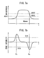
- Fig. 7 is diagram showing brightness characteristics of a horizontal line containing a lane marker. As understood from this characteristic diagram, a horizontal line where a lane marker exists, has following brightness characteristics:
- the horizontal line in which a lane marker exists has following distance characteristics:
- a candidate of lane marker is extracted based on brightness information of the image (brightness data stored in the image data memory 8).
- brightness information of the image brightness data stored in the image data memory 8
- lane a lane candidate
- lane points P (start point Ps and end point Pe) are found based on the aforesaid brightness characteristic according to the following conditions.
- the start point Ps denotes a lane point at an inside boarder of a lane marker and an asphalt surface
- the end point Pe denotes a lane point at an outside boarder of a lane marker and an asphalt surface.
- the threshold values Ath1, Ath2 are calculated based on the road surface brightness Aroad. That is, the threshold values Ath1, Ath2 are calculated by adding constants ⁇ , ⁇ (0 ⁇ ) to the road surface brightness Aroad, respectively.
- the calculation of the road surface brightness Aroad at the step 24 slightly differs from the calculation of the road surface brightness at the step 22 in the method of establishing the detection range R.
- the road surface brightness Aroad is calculated from the brightness over the entire areas of the pre-detection ranges PRE1, PRE2 as shown in Fig. 5.
- the sampling area of brightness is established in the pre-detection ranges PRE1, PRE2 excepting the outside of the lane.
- the reason why the sampling area is established so as not to include the outside of the lane is to prevent an inappropriate road surface brightness Aroad from being calculated due to objects outside of the lane.
- the center point (I, j) of the detection area Rj is regarded as the lane point Pj.
- a histogram of brightness of pixels in the sampling area is calculated, letting the brightness value most frequently observed be a road surface brightness Aroad.
- Fig. 12 is a diagram showing a difference of the brightness characteristic between a lane marker and others else(for example, stains and the like).
- the boarder of those and asphalt surface is mostly indistinct.
- the edge intensity of those objects has lower peaks than that of lane markers. From this point of view, if an appropriate threshold value Eth is selected, it is possible to clearly discriminate lane markers from other objects.
- two threshold values Ath1, Ath2 are established in order to raise the accuracy of lane detection.
- the threshold value Ath1 for judging a start point brightness to be relatively low.
- the threshold value Ath1 is applied uniformly, that is, the threshold value Ath1 is used also for the threshold value Ath2 for judging brightness of lane markers, there is a possibility that objects other than lane markers are detected as lane markers. For that reason, the threshold value Ath1 for judging the brightness at the detection of edge is established separately from the threshold value Ath2 for judging the brightness condition over the entire lane marker.
- a point satisfying these conditions on the object line j is a lane point Pj. It is not certain whether or not the lane point Pj exists on the road. Hence, in order to raise the accuracy of the result of detection, it is verified whether or not the lane point Pj obtained from brightness information exists on the road.
- a picture image as shown in Fig. 13 being considered, the picture image shows a brightness characteristic as shown in Fig. 14a depending upon colors, structures, direction of a vehicle traveling ahead of an own vehicle.
- the detection is dependent only upon brightness information, there is fear that a pillar on the preceding vehicle is detected as a lane marker. In this case, if distance information is concurrently used, as shown in Fig.
- Respective lane points P (i, j) thus obtained from both brightness and distance information are stored in RAM of the micro-computer 9.
- first a lane marker is detected form brightness information and then the result of detection is verified based on distance information.
- first objects on the road are extracted by processing distance information and then a lane marker may be identified based on brightness information.
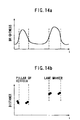
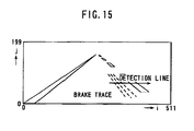
- a picture image as illustrated in Fig. 15 being considered, in case such a picture image, distance (parallax) to portions such as a brake trace and a Lane marker is calculated. Therefore, even when there are objects other than the road surface, those objects can be deleted by use of distance information.
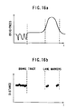
- brightness information is processed in the vicinity of the position where the distance is detected, only the lane marker can be extracted by judging the difference of brightness characteristic between lane markers and brake traces as shown in Fig 16a.
- the program goes from the step 25 to a step 26.
- the correction line jamd denotes a group of horizontal lines from ja to jb (jb ⁇ ja) established beforehand in a relatively low part of the image.
- a pitching amount of the own vehicle is calculated based on respective lane points P detected on respective correction lines jamd and a parallax d at a lane point P.
- the parallax d is a parallax calculated for pixel blocks including the lane points P and is stored in the distance data memory 7.
- the detection of the pitching condition is important in raising the accuracy of recognition not only of a road (lane markers) but also of an object (preceding vehicle) .
- a road height model is used in order to discriminate a preceding vehicle from an object on the road. That is, in case where an object exists on a higher side than the road surface specified by the road height model, that object can be regarded as a preceding vehicle.
- the amount of pitching is calculated as follows. First, at a step 24, respective lane points P(i, j) in the horizontal line group Jamd (correction line) are detected.
- the respective points P(i, j) indicate the position of a lane marker on a relatively lower side of the image, that is, a lane marker located in a sort distance (distance up to around 20 meters) .
- the road height in the present frame is calculated based on the lane points P thus sampled.
- the parallax d with respect to the respective lane points P is calculated.
- the parallax d of the respective lane points P is a parallax calculated with respect to a pixel block including the lane point P and stored in the distance data memory 7.
- coordinates (i, j) of the respective lane points P and a parallax d are identified as a set of coordinates (i, j, d).
- a set of coordinates (X, Y, Z) of a lane point P in real space can be unconditionally identified from the set of coordinates (i, j, d) thus obtained.
- X denotes a position in a widthwise direction of the vehicle
- Y denotes a position in a vertical (height) direction of the vehicle
- Z denotes a position in a longitudinal direction of the vehicle, that is, a distance.
- lane points P are plotted on a Y-Z (Y: height, Z: distance) plane and an approximation line L' is calculated by applying the least square method to the plotted lane points P. Further, a gradient a of the approximation line L' is calculated with respect to the road height model (road height L in a specified distance from the own vehicle) calculated in the previous frame.
- the pitching amount can be estimated from the gradient ⁇ . If the gradients ⁇ is positive, it means that the own vehicle is directed downward. As the absolute value of the gradient ⁇ is large, the pitching amount increases.
- the road height model calculated in the previous frame is corrected by thus calculated gradient ⁇ .
- the corrected road height model is used for calculating a road surface in the solid object recognition. Since the effect of pitching is reduced when the present solid object recognition is performed based on the corrected road height model, the accuracy of recognition can be raised.
- a roll angle of the own vehicle or a bank angle of a road can be obtained by calculating the height of left and right lane markers separately.
- the program goes from a step 27 to a step 28.
- the wide detection line jwide is a particular horizontal line established between the detection start line js and the detection end line je.
- a wide detection that is, a lane detection over the entire area of the wide detection line jwide is performed.
- the lane detection at the step 24 since the detection area R is established on the object line j for the reason of the detection accuracy and processing time, the lane detection is not performed outside of the detection area R. Accordingly, if the lane marker detected in a given horizontal line is right, a right lane marker is mostly detected in subsequent line. However, in case where a plurality of lane markers exist on one side of the road as shown in Fig. 18, there is a likelihood that a first lane marker is erroneously detected. For example, wherein a lane marker SL should have been detected, a lane marker SL' outside thereof is detected. In this case, there is a strong possibility that the same lane marker SL' is successively detected also in subsequent horizontal lines.
- a wide detection is a process in which all candidates of lane markers SL, SL' on the wide detection line jwide are detected.
- flag information showing a presence of lane candidates and respective lane points Psl, Ps1' are stored in RAM of the micro-computer 9. These information is used for evaluation of lane candidates at a later step 4.
- a counter j is incremented, the object line shifting from a horizontal line j to a horizontal line j+1. Further, according to the judgment at a step 30, aforegoing steps 21 through 29 are carried out for every horizontal line.
- step 3 "lane model” showing a three-dimensional (real space) position of lane marker is calculated.
- "lane points P" are read out from RAM in the micro-computer 9 and at the same time parallax data stored in the distance data memory 7 are read out.
- the lane model is calculated as follows. First, a parallax d of a lane point P is identified from parallaxes of one frame. Further, coordinates (i, j, d) for all lane points P are obtained from respective lane points P (i, j) and parallaxes d.
- a position (X, Y, Z) of left and right lane markers in real space is determined unconditionally according to the following formula:
- KZH is a base length of camera/angle of horizontal visual field
- DP is a parallax of a vanishing point
- CH is installation height of stereoscopic camera
- r installation interval of stereoscopic camera
- PW is an angle of view per one pixel
- IV is i-coordinate of an infinite point on image in front of vehicle
- JV j-coordinate of the infinite point.
- the coordinate system of image comprises an origin located at the left below corner, an i-axis extending in the horizontal direction and a j-axis extending in the vertical direction.
- Unit of coordinate axes is one pixel.
- a lane model is calculated from thus calculated position (X, Y, Z) of the lane point P in real space.
- the lane model expresses the left and right lanes within a recognition range (distance from the camera position to a specified position)as a combination of plurality of broken lines each of which is a three-dimensional approximation line calculated per specified interval (segment) respectively.
- An example of the lane model is shown in Fig. 8.
- the recognition range is divided into seven segments, letting a distance to the end point of respective intervals be Z1, Z2, Z3, Z4, Z5, Z6 and Z7 in a nearest order.
- an approximation line is prepared by applying the least square method to lane points P within respective segments.
- parameters a, b, c and d of approximation lines of segments are calculated with respect to left and right lane markers, respectively.
- the road surface is an area enclosed by left and right approximation lines L, R.
- This lane model also has a linear equation extending horizontally (X direction) or a horizontal configuration model and a linear equation extending vertically (Y direction) or a road height model, expressing road configurations such as gradients, unevenness of roads and the like.
- a value of X is calculated based on the coordinate transformation formula shown in Formula 2. Otherwise, the widthwise position of lane marker can be calculated by projecting the lane point P(i, j) on the road surface (an area enclosed by left and right lane markers in the road height model). Thus, a lane model showing a three-dimensional configuration is calculated.
- a three-dimensional position information concerning lane markers can be obtained.
- positional information enables to discriminate objects on the road (paint, manholes, patches and the like) from other obstacles else (man, vehicle, walls, buildings and the like) with accuracy.
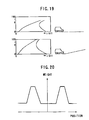
- the evaluation of candidates for lane marker is performed based on the result of the wide detection at a step 28. That is, in case where the object line is a wide detection line jwide and a plurality of objects supposed to be candidates for lane markers exist, respective candidates are evaluated. A time-versus histogram (accumulation of position data of lane markers obtained for each frame) is obtained with respect to the position of the candidates for lane markers detected (position on the horizontal line). At this time, the histogram is calculated being weighted by the position in which the candidates for lane markers are detected, as shown in Fig. 20.
- weight is established according to the position on the horizontal line so as to become largest in a specified area on the left and right sides with respect to the center of the vehicle.
- This area corresponds to an area in which lane markers are included with high likelihood. Accordingly, there is a strong possibility that the candidates existing in that area are real lane markers.
- the horizontal line being divided into a plurality of areas having a predetermined interval, the number of observations versus time is counted.
- an area including lane markers the value of the histogram corresponding to the area increases.
- an upper limit is provided in order to prevent the value from excessively increasing.
- the value of the histogram corresponding to the other area decreases.
- the lower limit is 0.
- weight may be varied according to vehicle speeds as follows.
- Weight is established to be small at low speeds. At low speeds, objects other than lane marker (paint on the road surface and the like) are detected successively and the histogram is accumulated due to the objects. To reduce the increasing rate of histogram, a small weight is applied at low speeds. Further, in case where speeds are smaller than a certain value, the detection may be stopped. Further, weight is established to be large at high speeds. Specifically, weight is established so as to be able to detect a dotted line (passing lane marker) with 6 meters interval.
- the candidates for lane markers are evaluated based on a histogram prepared according to the aforesaid method.
- a most probable candidate is referred to as a lane marker.
- thus detected lane marker is corrected at a step 7.
- the reliability of the lane marker is calculated.
- the position of the lane marker in real space is expressed in the lane model.
- an index representing reliability that is, a degree of reliability is expressed in figures.
- the lane model is not corrected by this degree of reliability.
- the degree of reliability is for giving an index of reliability to other processes for recognition using the lane model.
- the degree of reliability calculated this time is used for determining the size of the detection area R to be established next at the step 23.
- the degree of reliability is calculated in consideration of the number of the lane points P detected and the continuity of the lane points P detected in the previous frame. That is, in case where the lane points P are detected successively, it is judged that the reliability is high. Then, the utility of the reliability can be enhanced further more by calculating the reliability of lane marker for every segment as shown in Fig. 8.
- the reliability is calculated according to the following method for example.
- the degree of reliability D is calculated for each segment according to the presence or absence of data.
- the degree of reliability D calculated in the previous cycle for a given segment is incremented or decremented according to the number of sample points as the calculation base of the lane model for that segment.
- the present degree of reliability D is calculated. Accordingly, if the sample points are calculated successively within a certain segment, the degree of reliability D increases. To prevent an excessive increase, an upper limit is provided.
- the degree of reliability D is decremented.
- the positional deviation between the previous lane model and the present lane model is obtained for every segment and the degree of reliability D is incremented or decremented according to the deviation amount. Accordingly, in case where the positional deviation occurs successively, the reliability goes down.
- the parallelization of left and right lane markers is evaluated. Normally, left and right lane markers are parallel wit each other. Therefore, otherwise, there is a strong likelihood that the lane makers are recognized erroneously.
- the parallelization of the left and right lane model is evaluated. Further, in case where some abnormality is found with respect to the parallelization, it is judged that those lane markers have been recognized erroneously and at a step 7 the present lane model is corrected. For example, in case where the interval of the left and right lane markers becomes larger (wider) as they goes far, either one is treated as abnormal. Such a case often happens when the lane is pronged.
- a lane marker extending in the same direction as the vehicle traveling direction is a right one, correcting the abnormal one so as to run in parallel with the other one (step 7) .
- a lane marker with lower reliability is treated as erroneous recognition, the lane model being corrected (step 7).
Landscapes
- Engineering & Computer Science (AREA)
- Physics & Mathematics (AREA)
- General Physics & Mathematics (AREA)
- Multimedia (AREA)
- Theoretical Computer Science (AREA)
- Computer Vision & Pattern Recognition (AREA)
- Signal Processing (AREA)
- Electromagnetism (AREA)
- Radar, Positioning & Navigation (AREA)
- Remote Sensing (AREA)
- Image Processing (AREA)
- Traffic Control Systems (AREA)
- Image Analysis (AREA)
- Closed-Circuit Television Systems (AREA)
- Control Of Position, Course, Altitude, Or Attitude Of Moving Bodies (AREA)
Applications Claiming Priority (2)
| Application Number | Priority Date | Filing Date | Title |
|---|---|---|---|
| JP26957899A JP3352655B2 (ja) | 1999-09-22 | 1999-09-22 | 車線認識装置 |
| JP26957899 | 1999-09-22 |
Publications (2)
| Publication Number | Publication Date |
|---|---|
| EP1089231A2 true EP1089231A2 (fr) | 2001-04-04 |
| EP1089231A3 EP1089231A3 (fr) | 2003-06-18 |
Family
ID=17474327
Family Applications (1)
| Application Number | Title | Priority Date | Filing Date |
|---|---|---|---|
| EP00308351A Withdrawn EP1089231A3 (fr) | 1999-09-22 | 2000-09-22 | Dispositif pour la reconnaissance des lignes de marquage routières |
Country Status (3)
| Country | Link |
|---|---|
| US (1) | US6813370B1 (fr) |
| EP (1) | EP1089231A3 (fr) |
| JP (1) | JP3352655B2 (fr) |
Cited By (20)
| Publication number | Priority date | Publication date | Assignee | Title |
|---|---|---|---|---|
| GB2373941A (en) * | 2000-10-17 | 2002-10-02 | Advanced Realtime Tracking Gmb | Stereogrammetry with camera and window tracking |
| EP1311130A2 (fr) * | 2001-11-08 | 2003-05-14 | Fuji Jukogyo Kabushiki Kaisha | Méthode de mise en correspondance d'images stéréoscopiques en couleurs |
| WO2004041611A1 (fr) * | 2002-11-08 | 2004-05-21 | Robert Bosch Gmbh | Regulation du comportement dynamique de roulement faisant appel a un systeme capteur d'images |
| WO2007010750A1 (fr) | 2005-07-15 | 2007-01-25 | Honda Motor Co., Ltd. | Véhicule, système, procédé et programme de traitement d'image, système de structure de système de traitement d'image |
| EP1940181A1 (fr) * | 2006-12-27 | 2008-07-02 | Matsushita Electric Industrial Co., Ltd. | Dispositif d'imagerie à semi-conducteurs, caméra, véhicule et procédé de surveillance |
| DE102007051967A1 (de) * | 2007-10-31 | 2009-05-07 | Adc Automotive Distance Control Systems Gmbh | Detektor und Verfahren zum Erkennen einer Fahrspurbegrenzung |
| WO2013020550A3 (fr) * | 2011-08-05 | 2013-04-11 | Conti Temic Microelectronic Gmbh | Procédé de reconnaissance d'une voie de circulation au moyen d'une caméra |
| WO2013116598A1 (fr) * | 2012-02-03 | 2013-08-08 | Analog Devices, Inc. | Détection peu coûteuse de plots de marquage de couloirs |
| EP2000979A4 (fr) * | 2006-03-28 | 2013-10-09 | Pasco Corp | Dispositif et procede d'analyse d'image video de route |
| DE102012008780A1 (de) * | 2012-04-28 | 2013-10-31 | Volkswagen Aktiengesellschaft | Verfahren und Einrichtung zur Erfassung wenigstens eines Fahrbahnrandes und Kraftfahrzeug |
| WO2014032904A1 (fr) * | 2012-08-29 | 2014-03-06 | Robert Bosch Gmbh | Procédé et dispositif de détection de la position d'un véhicule sur une voie de circulation |
| EP2720173A3 (fr) * | 2012-10-10 | 2015-01-07 | Ricoh Company, Ltd. | Appareil et procédé de reconnaissance de ligne et support de programme de reconnaissance de ligne |
| US9132837B2 (en) | 2013-04-26 | 2015-09-15 | Conti Temic Microelectronic Gmbh | Method and device for estimating the number of lanes and/or the lane width on a roadway |
| EP2674893A3 (fr) * | 2012-06-15 | 2016-11-09 | Ricoh Company, Ltd. | Système de reconnaissance de zone de déplacement, procédé de reconnaissance de zone de déplacement, programme de reconnaissance de zone circulable exécuté sur le système de reconnaissance de zone de déplacement et support d'enregistrement stockant un programme de reconnaissance de zone de déplacement possible |
| CN106295607A (zh) * | 2016-08-19 | 2017-01-04 | 北京奇虎科技有限公司 | 道路识别方法及装置 |
| DE102010020867B4 (de) * | 2009-05-22 | 2017-12-28 | Subaru Corporation | Strassenform-Erkennungsvorrichtung |
| DE112005001307B4 (de) | 2004-06-02 | 2018-08-02 | Clarion Co., Ltd. | Eingebaute Navigationsvorrichtung und Verfahren zur Korrektur der eigenen Fahrzeugposition |
| WO2020048659A1 (fr) * | 2018-09-06 | 2020-03-12 | Renault S.A.S | Procédé de détection de faux positifs d'un dispositif de traitement d'image d'une caméra |
| CN111832340A (zh) * | 2019-04-16 | 2020-10-27 | 杭州海康威视数字技术股份有限公司 | 一种停车入库方法、装置和系统 |
| CN112985360A (zh) * | 2021-05-06 | 2021-06-18 | 中汽数据(天津)有限公司 | 基于车道线的双目测距校正方法、装置、设备和存储介质 |
Families Citing this family (103)
| Publication number | Priority date | Publication date | Assignee | Title |
|---|---|---|---|---|
| US6822563B2 (en) | 1997-09-22 | 2004-11-23 | Donnelly Corporation | Vehicle imaging system with accessory control |
| US5877897A (en) | 1993-02-26 | 1999-03-02 | Donnelly Corporation | Automatic rearview mirror, vehicle lighting control and vehicle interior monitoring system using a photosensor array |
| US6891563B2 (en) | 1996-05-22 | 2005-05-10 | Donnelly Corporation | Vehicular vision system |
| US7655894B2 (en) | 1996-03-25 | 2010-02-02 | Donnelly Corporation | Vehicular image sensing system |
| JP3587506B2 (ja) * | 1999-08-30 | 2004-11-10 | 富士重工業株式会社 | ステレオカメラの調整装置 |
| JP4925498B2 (ja) | 2000-07-12 | 2012-04-25 | 富士重工業株式会社 | フェールセーフ機能を有する車外監視装置 |
| JP4953498B2 (ja) | 2000-07-12 | 2012-06-13 | 富士重工業株式会社 | フェールセーフ機能を有する車外監視装置 |
| US6978037B1 (en) * | 2000-11-01 | 2005-12-20 | Daimlerchrysler Ag | Process for recognition of lane markers using image data |
| JP3992452B2 (ja) * | 2000-11-09 | 2007-10-17 | 日立ソフトウエアエンジニアリング株式会社 | 変化検出装置、変化検出方法及び該方法に係るプログラムを記憶した記憶媒体並びにシステム |
| JP3462467B2 (ja) | 2000-11-14 | 2003-11-05 | 富士重工業株式会社 | 車外監視装置 |
| JP3736346B2 (ja) * | 2000-12-26 | 2006-01-18 | 日産自動車株式会社 | 車線検出装置 |
| KR20020053346A (ko) * | 2000-12-27 | 2002-07-05 | 이계안 | 차선 모델링 시스템의 곡선로 인식방법 |
| JP2002316601A (ja) * | 2001-04-19 | 2002-10-29 | Mitsubishi Motors Corp | 運転支援装置 |
| US6882287B2 (en) | 2001-07-31 | 2005-04-19 | Donnelly Corporation | Automotive lane change aid |
| JP3780922B2 (ja) * | 2001-11-30 | 2006-05-31 | 日産自動車株式会社 | 道路白線認識装置 |
| WO2003093857A2 (fr) | 2002-05-03 | 2003-11-13 | Donnelly Corporation | Systeme de detection d'objets pour vehicule |
| JP4374211B2 (ja) * | 2002-08-27 | 2009-12-02 | クラリオン株式会社 | レーンマーカー位置検出方法及びレーンマーカー位置検出装置並びに車線逸脱警報装置 |
| JP4100146B2 (ja) * | 2002-11-27 | 2008-06-11 | ソニー株式会社 | 双方向コミュニケーションシステム,映像通信装置 |
| JP3977776B2 (ja) * | 2003-03-13 | 2007-09-19 | 株式会社東芝 | ステレオキャリブレーション装置とそれを用いたステレオ画像監視装置 |
| US7688222B2 (en) | 2003-09-18 | 2010-03-30 | Spot Devices, Inc. | Methods, systems and devices related to road mounted indicators for providing visual indications to approaching traffic |
| US7482916B2 (en) | 2004-03-15 | 2009-01-27 | Anita Au | Automatic signaling systems for vehicles |
| JP4451179B2 (ja) * | 2004-03-26 | 2010-04-14 | クラリオン株式会社 | 車線位置検知システム |
| JP4445311B2 (ja) * | 2004-03-31 | 2010-04-07 | 株式会社デンソーアイティーラボラトリ | 物体検知装置 |
| US7526103B2 (en) | 2004-04-15 | 2009-04-28 | Donnelly Corporation | Imaging system for vehicle |
| JP4093208B2 (ja) * | 2004-05-28 | 2008-06-04 | トヨタ自動車株式会社 | 車両用走路判定装置 |
| JP4491777B2 (ja) * | 2004-06-04 | 2010-06-30 | 富士ゼロックス株式会社 | 画像表示装置、画像表示方法及びそのプログラム |
| JP4756931B2 (ja) * | 2004-07-01 | 2011-08-24 | 株式会社 三英技研 | デジタルレーンマーク作成装置 |
| DE102004040143A1 (de) * | 2004-08-19 | 2006-02-23 | Robert Bosch Gmbh | Verfahren und Vorrichtung zur Fahrerinformation |
| US7639841B2 (en) * | 2004-12-20 | 2009-12-29 | Siemens Corporation | System and method for on-road detection of a vehicle using knowledge fusion |
| JP4341564B2 (ja) * | 2005-02-25 | 2009-10-07 | 株式会社豊田中央研究所 | 対象物判定装置 |
| JP4616046B2 (ja) * | 2005-03-22 | 2011-01-19 | 本田技研工業株式会社 | 車両用画像処理システム、車両用画像処理方法、車両用画像処理プログラム、及び車両 |
| JP4659631B2 (ja) | 2005-04-26 | 2011-03-30 | 富士重工業株式会社 | 車線認識装置 |
| JP4616068B2 (ja) * | 2005-04-28 | 2011-01-19 | 本田技研工業株式会社 | 車両、画像処理システム、画像処理方法及び画像処理プログラム |
| JP4244964B2 (ja) * | 2005-06-06 | 2009-03-25 | オムロン株式会社 | 車両用測距装置 |
| DE102005044979A1 (de) * | 2005-09-20 | 2007-03-22 | Adc Automotive Distance Control Systems Gmbh | Verfahren zur Erkennung von Fahrspurmarkierungen |
| JP2007148835A (ja) * | 2005-11-28 | 2007-06-14 | Fujitsu Ten Ltd | 物体判別装置、報知制御装置、物体判別方法および物体判別プログラム |
| JP4607193B2 (ja) * | 2005-12-28 | 2011-01-05 | 本田技研工業株式会社 | 車両及びレーンマーク検出装置 |
| US8676492B2 (en) * | 2006-01-19 | 2014-03-18 | GM Global Technology Operations LLC | Map-aided vision-based lane sensing |
| JP4821348B2 (ja) * | 2006-02-07 | 2011-11-24 | トヨタ自動車株式会社 | 道路区間線検出装置及び方法並びにプログラム |
| JP4733545B2 (ja) * | 2006-03-27 | 2011-07-27 | 富士重工業株式会社 | 車線認識装置 |
| JP4638370B2 (ja) | 2006-03-29 | 2011-02-23 | 富士重工業株式会社 | 車線逸脱防止装置 |
| JP4721279B2 (ja) | 2006-03-29 | 2011-07-13 | 富士重工業株式会社 | 車線追従支援装置 |
| JP4793094B2 (ja) * | 2006-05-17 | 2011-10-12 | 株式会社デンソー | 走行環境認識装置 |
| US7972045B2 (en) | 2006-08-11 | 2011-07-05 | Donnelly Corporation | Automatic headlamp control system |
| JP4956099B2 (ja) * | 2006-08-31 | 2012-06-20 | 富士重工業株式会社 | 壁検出装置 |
| JP4189826B2 (ja) * | 2006-12-01 | 2008-12-03 | 村田機械株式会社 | 走行台車と走行台車システム |
| JP4775658B2 (ja) * | 2006-12-27 | 2011-09-21 | アイシン・エィ・ダブリュ株式会社 | 地物認識装置・自車位置認識装置・ナビゲーション装置・地物認識方法 |
| JP5221886B2 (ja) * | 2007-03-07 | 2013-06-26 | 富士重工業株式会社 | 物体検出装置 |
| TWI334517B (en) * | 2007-08-30 | 2010-12-11 | Ind Tech Res Inst | Method for predicting lane line and lane departure warning system using the same |
| EP2056235A1 (fr) * | 2007-11-02 | 2009-05-06 | Honda Research Institute Europe GmbH | Identification de la voie de conduite par l'adaptation en ligne du modèle de voie de conduite |
| JP4937933B2 (ja) * | 2008-01-18 | 2012-05-23 | 富士重工業株式会社 | 車外監視装置 |
| KR101176693B1 (ko) * | 2008-03-13 | 2012-08-23 | 주식회사 만도 | 거리센서를 이용한 차선인식 방법 및 그 시스템 |
| JP2010006270A (ja) * | 2008-06-27 | 2010-01-14 | Toyota Motor Corp | 車両挙動検出装置 |
| JP4692613B2 (ja) * | 2008-11-28 | 2011-06-01 | トヨタ自動車株式会社 | 車載装置、及び当該装置で用いられる方法 |
| JP4862898B2 (ja) * | 2009-01-09 | 2012-01-25 | 株式会社デンソー | 車両用警報発生装置 |
| US8306269B2 (en) * | 2009-03-12 | 2012-11-06 | Honda Motor Co., Ltd. | Lane recognition device |
| KR101163446B1 (ko) * | 2009-03-18 | 2012-07-18 | 기아자동차주식회사 | 가상 차선을 이용하는 차선 이탈 경보 방법 및 그에 따른 시스템 |
| JP5075152B2 (ja) * | 2009-03-24 | 2012-11-14 | 日立オートモティブシステムズ株式会社 | 車両制御装置 |
| JP4927908B2 (ja) * | 2009-05-29 | 2012-05-09 | クラリオン株式会社 | 車線位置検知システム |
| CN102596517B (zh) * | 2009-07-28 | 2015-06-17 | 悠进机器人股份公司 | 移动机器人定位和导航控制方法及使用该方法的移动机器人 |
| JP5039765B2 (ja) * | 2009-09-17 | 2012-10-03 | 日立オートモティブシステムズ株式会社 | 車両制御装置 |
| JP5286214B2 (ja) * | 2009-09-30 | 2013-09-11 | 日立オートモティブシステムズ株式会社 | 車両制御装置 |
| JP5502448B2 (ja) * | 2009-12-17 | 2014-05-28 | 富士重工業株式会社 | 路面形状認識装置 |
| JP4962581B2 (ja) * | 2010-03-03 | 2012-06-27 | 株式会社デンソー | 区画線検出装置 |
| JP5035371B2 (ja) | 2010-03-15 | 2012-09-26 | アイシン精機株式会社 | 横断歩道検出装置、横断歩道検出システム,横断歩道検出方法及びプログラム |
| JP5652699B2 (ja) * | 2010-07-07 | 2015-01-14 | スズキ株式会社 | 白線検出装置 |
| US9280711B2 (en) * | 2010-09-21 | 2016-03-08 | Mobileye Vision Technologies Ltd. | Barrier and guardrail detection using a single camera |
| US8773535B2 (en) * | 2010-12-08 | 2014-07-08 | GM Global Technology Operations LLC | Adaptation for clear path detection using reliable local model updating |
| JP5687712B2 (ja) * | 2010-12-15 | 2015-03-18 | 本田技研工業株式会社 | レーン認識装置 |
| US20130006482A1 (en) * | 2011-06-30 | 2013-01-03 | Ramadev Burigsay Hukkeri | Guidance system for a mobile machine |
| US9098751B2 (en) * | 2011-07-27 | 2015-08-04 | Gentex Corporation | System and method for periodic lane marker identification and tracking |
| CN103177236B (zh) | 2011-12-22 | 2016-06-01 | 株式会社理光 | 道路区域检测方法和装置、分道线检测方法和装置 |
| US10246030B2 (en) * | 2012-08-09 | 2019-04-02 | Toyota Jidosha Kabushiki Kaisha | Object detection apparatus and driving assistance apparatus |
| JP6064648B2 (ja) * | 2013-01-09 | 2017-01-25 | 株式会社リコー | 画像処理装置、画像処理方法、画像処理プログラム、画像処理システム及び移動装置 |
| US8880273B1 (en) | 2013-01-16 | 2014-11-04 | Google Inc. | System and method for determining position and distance of objects using road fiducials |
| JP6111732B2 (ja) * | 2013-02-22 | 2017-04-12 | 株式会社リコー | 画像処理装置、画像処理方法、画像処理システム、画像処理プログラム及び移動装置 |
| JP6151150B2 (ja) * | 2013-10-07 | 2017-06-21 | 日立オートモティブシステムズ株式会社 | 物体検出装置及びそれを用いた車両 |
| US9365214B2 (en) | 2014-01-30 | 2016-06-14 | Mobileye Vision Technologies Ltd. | Systems and methods for determining the status of a turn lane traffic light |
| JP6087858B2 (ja) * | 2014-03-24 | 2017-03-01 | 株式会社日本自動車部品総合研究所 | 走行区画線認識装置及び走行区画線認識プログラム |
| JP6210012B2 (ja) * | 2014-03-28 | 2017-10-11 | マツダ株式会社 | 車線維持制御装置 |
| JP5906272B2 (ja) * | 2014-03-28 | 2016-04-20 | 富士重工業株式会社 | 車両用ステレオ画像処理装置 |
| JP6130809B2 (ja) * | 2014-04-25 | 2017-05-17 | 本田技研工業株式会社 | 車線認識装置 |
| EP2960129A1 (fr) * | 2014-06-26 | 2015-12-30 | Volvo Car Corporation | Détermination du niveau de confiance pour des géométries de route estimées |
| CN105674992A (zh) * | 2014-11-20 | 2016-06-15 | 高德软件有限公司 | 一种导航方法及装置 |
| JP6233345B2 (ja) * | 2015-04-17 | 2017-11-22 | トヨタ自動車株式会社 | 路面勾配検出装置 |
| US10373338B2 (en) * | 2015-05-27 | 2019-08-06 | Kyocera Corporation | Calculation device, camera device, vehicle, and calibration method |
| WO2017029734A1 (fr) * | 2015-08-19 | 2017-02-23 | 三菱電機株式会社 | Dispositif de reconnaissance de voie de circulation et procédé de reconnaissance de voie de circulation |
| JP6174644B2 (ja) * | 2015-09-01 | 2017-08-02 | 本田技研工業株式会社 | 画像処理装置 |
| US9761000B2 (en) * | 2015-09-18 | 2017-09-12 | Qualcomm Incorporated | Systems and methods for non-obstacle area detection |
| KR101755870B1 (ko) * | 2015-10-28 | 2017-07-19 | 현대자동차주식회사 | 차선의 오인식 정보를 보정하는 방법 |
| KR20180051836A (ko) | 2016-11-09 | 2018-05-17 | 삼성전자주식회사 | 주행 차량을 위한 가상의 주행 차선을 생성하는 방법 및 장치 |
| WO2018212286A1 (fr) * | 2017-05-19 | 2018-11-22 | パイオニア株式会社 | Dispositif de mesure, procédé de mesure et programme |
| WO2018212284A1 (fr) * | 2017-05-19 | 2018-11-22 | パイオニア株式会社 | Dispositif de mesure, procédé de mesure et programme |
| US11519727B2 (en) * | 2017-05-19 | 2022-12-06 | Pioneer Corporation | Measurement device, measurement method and program |
| JP6879881B2 (ja) * | 2017-10-13 | 2021-06-02 | 株式会社Subaru | 車両用白線認識装置 |
| JP7007856B2 (ja) * | 2017-10-27 | 2022-01-25 | 株式会社Subaru | 車両用白線認識装置 |
| WO2019124278A1 (fr) * | 2017-12-19 | 2019-06-27 | パイオニア株式会社 | Dispositif de traitement d'informations |
| US10614320B2 (en) | 2018-04-03 | 2020-04-07 | Honda Motor Co., Ltd. | System and method for advanced highway lane detection |
| US10878709B2 (en) * | 2018-07-19 | 2020-12-29 | The Boeing Company | System, method, and computer readable medium for autonomous airport runway navigation |
| JP7229710B2 (ja) * | 2018-09-26 | 2023-02-28 | 本田技研工業株式会社 | 車両制御装置、車両制御方法、およびプログラム |
| CN112785595B (zh) * | 2019-11-07 | 2023-02-28 | 北京市商汤科技开发有限公司 | 目标属性检测、神经网络训练及智能行驶方法、装置 |
| US10867190B1 (en) | 2019-11-27 | 2020-12-15 | Aimotive Kft. | Method and system for lane detection |
| JP2022150929A (ja) * | 2021-03-26 | 2022-10-07 | 本田技研工業株式会社 | 軸ずれ推定装置 |
Family Cites Families (14)
| Publication number | Priority date | Publication date | Assignee | Title |
|---|---|---|---|---|
| JP3167752B2 (ja) | 1991-10-22 | 2001-05-21 | 富士重工業株式会社 | 車輌用距離検出装置 |
| JPH07505966A (ja) * | 1992-03-20 | 1995-06-29 | コモンウエルス サイエンティフィック アンド インダストリアル リサーチ オーガナイゼーション | 物体モニタシステム |
| JPH05265547A (ja) | 1992-03-23 | 1993-10-15 | Fuji Heavy Ind Ltd | 車輌用車外監視装置 |
| JP2861638B2 (ja) | 1992-06-16 | 1999-02-24 | 松下電器産業株式会社 | 走行レーン検出装置 |
| US5487116A (en) * | 1993-05-25 | 1996-01-23 | Matsushita Electric Industrial Co., Ltd. | Vehicle recognition apparatus |
| US6553130B1 (en) * | 1993-08-11 | 2003-04-22 | Jerome H. Lemelson | Motor vehicle warning and control system and method |
| JP3352216B2 (ja) | 1994-03-30 | 2002-12-03 | マツダ株式会社 | 走行路認識装置 |
| JP3326988B2 (ja) | 1994-09-20 | 2002-09-24 | 富士通株式会社 | 道路環境認識装置 |
| DE19507957C1 (de) * | 1995-03-07 | 1996-09-12 | Daimler Benz Ag | Fahrzeug mit optischer Abtasteinrichtung für einen seitlichen Fahrbahnbereich |
| US5708427A (en) * | 1996-04-18 | 1998-01-13 | Bush; E. William | Vehicle in-lane positional indication/control by phase detection of RF signals induced in completely-passive resonant-loop circuits buried along a road lane |
| JPH09325026A (ja) | 1996-06-03 | 1997-12-16 | Nissan Motor Co Ltd | 前方道路の勾配検出方法及び勾配角検出方法 |
| JP3373773B2 (ja) * | 1998-01-27 | 2003-02-04 | 株式会社デンソー | レーンマーク認識装置、車両走行制御装置および記録媒体 |
| JP4021026B2 (ja) * | 1998-01-29 | 2007-12-12 | 富士重工業株式会社 | ステレオ画像処理システム |
| US6591000B1 (en) * | 1998-04-21 | 2003-07-08 | Denso Corporation | Apparatus and method for preprocessing a picked-up image, lane mark recognizing system, related vehicle traveling control system, and recording media |
-
1999
- 1999-09-22 JP JP26957899A patent/JP3352655B2/ja not_active Expired - Fee Related
-
2000
- 2000-09-22 EP EP00308351A patent/EP1089231A3/fr not_active Withdrawn
- 2000-09-22 US US09/667,535 patent/US6813370B1/en not_active Expired - Lifetime
Non-Patent Citations (1)
| Title |
|---|
| None * |
Cited By (33)
| Publication number | Priority date | Publication date | Assignee | Title |
|---|---|---|---|---|
| GB2373941A (en) * | 2000-10-17 | 2002-10-02 | Advanced Realtime Tracking Gmb | Stereogrammetry with camera and window tracking |
| EP1311130A2 (fr) * | 2001-11-08 | 2003-05-14 | Fuji Jukogyo Kabushiki Kaisha | Méthode de mise en correspondance d'images stéréoscopiques en couleurs |
| EP1311130A3 (fr) * | 2001-11-08 | 2004-08-18 | Fuji Jukogyo Kabushiki Kaisha | Méthode de mise en correspondance d'images stéréoscopiques en couleurs |
| US7065245B2 (en) | 2001-11-08 | 2006-06-20 | Fuji Jukogyo Kabushiki Kaisha | Image processing apparatus and the method thereof |
| US8108097B2 (en) | 2002-11-08 | 2012-01-31 | Robert Bosch Gmbh | Controlling vehicle dynamics through the use of an image sensor system |
| WO2004041611A1 (fr) * | 2002-11-08 | 2004-05-21 | Robert Bosch Gmbh | Regulation du comportement dynamique de roulement faisant appel a un systeme capteur d'images |
| DE112005001307B4 (de) | 2004-06-02 | 2018-08-02 | Clarion Co., Ltd. | Eingebaute Navigationsvorrichtung und Verfahren zur Korrektur der eigenen Fahrzeugposition |
| EP1914700A4 (fr) * | 2005-07-15 | 2008-11-26 | Honda Motor Co Ltd | Véhicule, système, procédé et programme de traitement d'image, système de structure de système de traitement d'image |
| US8170285B2 (en) | 2005-07-15 | 2012-05-01 | Honda Motor Co., Ltd. | Systems and methods of vehicle image processing |
| EP1914700A1 (fr) * | 2005-07-15 | 2008-04-23 | HONDA MOTOR CO., Ltd. | Véhicule, système, procédé et programme de traitement d'image, système de structure de système de traitement d'image |
| WO2007010750A1 (fr) | 2005-07-15 | 2007-01-25 | Honda Motor Co., Ltd. | Véhicule, système, procédé et programme de traitement d'image, système de structure de système de traitement d'image |
| EP2000979A4 (fr) * | 2006-03-28 | 2013-10-09 | Pasco Corp | Dispositif et procede d'analyse d'image video de route |
| EP1940181A1 (fr) * | 2006-12-27 | 2008-07-02 | Matsushita Electric Industrial Co., Ltd. | Dispositif d'imagerie à semi-conducteurs, caméra, véhicule et procédé de surveillance |
| DE102007051967A1 (de) * | 2007-10-31 | 2009-05-07 | Adc Automotive Distance Control Systems Gmbh | Detektor und Verfahren zum Erkennen einer Fahrspurbegrenzung |
| US8355540B2 (en) | 2007-10-31 | 2013-01-15 | Adc Automotive Distance Controls Systems Gmbh | Detector and method for identifying a road lane boundary |
| DE102010020867B4 (de) * | 2009-05-22 | 2017-12-28 | Subaru Corporation | Strassenform-Erkennungsvorrichtung |
| US9257045B2 (en) | 2011-08-05 | 2016-02-09 | Conti Temic Microelectronic Gmbh | Method for detecting a traffic lane by means of a camera |
| WO2013020550A3 (fr) * | 2011-08-05 | 2013-04-11 | Conti Temic Microelectronic Gmbh | Procédé de reconnaissance d'une voie de circulation au moyen d'une caméra |
| WO2013116598A1 (fr) * | 2012-02-03 | 2013-08-08 | Analog Devices, Inc. | Détection peu coûteuse de plots de marquage de couloirs |
| DE102012008780A1 (de) * | 2012-04-28 | 2013-10-31 | Volkswagen Aktiengesellschaft | Verfahren und Einrichtung zur Erfassung wenigstens eines Fahrbahnrandes und Kraftfahrzeug |
| EP2674893A3 (fr) * | 2012-06-15 | 2016-11-09 | Ricoh Company, Ltd. | Système de reconnaissance de zone de déplacement, procédé de reconnaissance de zone de déplacement, programme de reconnaissance de zone circulable exécuté sur le système de reconnaissance de zone de déplacement et support d'enregistrement stockant un programme de reconnaissance de zone de déplacement possible |
| WO2014032904A1 (fr) * | 2012-08-29 | 2014-03-06 | Robert Bosch Gmbh | Procédé et dispositif de détection de la position d'un véhicule sur une voie de circulation |
| US9569673B2 (en) | 2012-08-29 | 2017-02-14 | Robert Bosch Gmbh | Method and device for detecting a position of a vehicle on a lane |
| US9286523B2 (en) | 2012-10-10 | 2016-03-15 | Ricoh Company, Ltd. | Line recognition apparatus, line recognition method and line recognition program storage medium |
| EP2720173A3 (fr) * | 2012-10-10 | 2015-01-07 | Ricoh Company, Ltd. | Appareil et procédé de reconnaissance de ligne et support de programme de reconnaissance de ligne |
| US9132837B2 (en) | 2013-04-26 | 2015-09-15 | Conti Temic Microelectronic Gmbh | Method and device for estimating the number of lanes and/or the lane width on a roadway |
| CN106295607A (zh) * | 2016-08-19 | 2017-01-04 | 北京奇虎科技有限公司 | 道路识别方法及装置 |
| WO2020048659A1 (fr) * | 2018-09-06 | 2020-03-12 | Renault S.A.S | Procédé de détection de faux positifs d'un dispositif de traitement d'image d'une caméra |
| FR3085746A1 (fr) * | 2018-09-06 | 2020-03-13 | Renault S.A.S. | Procede de detection de faux positifs d’un dispositif de traitement d’image d’une camera |
| US11852497B2 (en) | 2018-09-06 | 2023-12-26 | Renault S.A.S. | Method for detecting false positives of an image-processing device of a camera |
| CN111832340A (zh) * | 2019-04-16 | 2020-10-27 | 杭州海康威视数字技术股份有限公司 | 一种停车入库方法、装置和系统 |
| CN111832340B (zh) * | 2019-04-16 | 2023-08-29 | 杭州海康威视数字技术股份有限公司 | 一种停车入库方法、装置和系统 |
| CN112985360A (zh) * | 2021-05-06 | 2021-06-18 | 中汽数据(天津)有限公司 | 基于车道线的双目测距校正方法、装置、设备和存储介质 |
Also Published As
| Publication number | Publication date |
|---|---|
| JP3352655B2 (ja) | 2002-12-03 |
| EP1089231A3 (fr) | 2003-06-18 |
| JP2001092970A (ja) | 2001-04-06 |
| US6813370B1 (en) | 2004-11-02 |
Similar Documents
| Publication | Publication Date | Title |
|---|---|---|
| US6813370B1 (en) | Lane marker recognizing apparatus | |
| US8244027B2 (en) | Vehicle environment recognition system | |
| US7046822B1 (en) | Method of detecting objects within a wide range of a road vehicle | |
| US6370261B1 (en) | Vehicle surroundings monitoring apparatus | |
| EP1944734B1 (fr) | Appareil de correction de distance d'un système de surveillance environnant et son appareil de correction de point de vue | |
| JP4714104B2 (ja) | 物体傾き検出装置 | |
| US6122597A (en) | Vehicle monitoring apparatus | |
| JP3671825B2 (ja) | 車間距離推定装置 | |
| JP3931891B2 (ja) | 車載用画像処理装置 | |
| US20090190827A1 (en) | Environment recognition system | |
| JP4937933B2 (ja) | 車外監視装置 | |
| KR101103526B1 (ko) | 스테레오 카메라를 이용한 충돌회피 방법 | |
| US20090052742A1 (en) | Image processing apparatus and method thereof | |
| JP6837262B2 (ja) | 走行可能領域検出装置及び走行支援システム | |
| KR101035761B1 (ko) | 차선 인식을 위한 영상 처리 방법 및 시스템 | |
| JP2012088217A (ja) | 運転支援制御装置 | |
| JP4939137B2 (ja) | 車線認識装置 | |
| JP4067340B2 (ja) | 対象物認識装置および対象物認識方法 | |
| JP4956099B2 (ja) | 壁検出装置 | |
| JP3462467B2 (ja) | 車外監視装置 | |
| CN113994663A (zh) | 立体图像处理装置及立体图像处理方法 | |
| JP3384526B2 (ja) | 物流計測装置 | |
| CN110488320A (zh) | 一种利用立体视觉检测车辆距离的方法 | |
| KR101313763B1 (ko) | 적분 영상 픽셀값을 이용한 차선 인식 방법 | |
| JP2023089311A (ja) | 情報処理装置、撮像システム、情報処理方法及びコンピュータプログラム |
Legal Events
| Date | Code | Title | Description |
|---|---|---|---|
| PUAI | Public reference made under article 153(3) epc to a published international application that has entered the european phase |
Free format text: ORIGINAL CODE: 0009012 |
|
| AK | Designated contracting states |
Kind code of ref document: A2 Designated state(s): AT BE CH CY DE DK ES FI FR GB GR IE IT LI LU MC NL PT SE |
|
| AX | Request for extension of the european patent |
Free format text: AL;LT;LV;MK;RO;SI |
|
| PUAL | Search report despatched |
Free format text: ORIGINAL CODE: 0009013 |
|
| AK | Designated contracting states |
Designated state(s): AT BE CH CY DE DK ES FI FR GB GR IE IT LI LU MC NL PT SE |
|
| AX | Request for extension of the european patent |
Extension state: AL LT LV MK RO SI |
|
| 17P | Request for examination filed |
Effective date: 20030922 |
|
| AKX | Designation fees paid |
Designated state(s): DE GB |
|
| RAP1 | Party data changed (applicant data changed or rights of an application transferred) |
Owner name: FUJI JUKOGYO KABUSHIKI KAISHA |
|
| RAP1 | Party data changed (applicant data changed or rights of an application transferred) |
Owner name: SUBARU CORPORATION |
|
| GRAP | Despatch of communication of intention to grant a patent |
Free format text: ORIGINAL CODE: EPIDOSNIGR1 |
|
| INTG | Intention to grant announced |
Effective date: 20180410 |
|
| STAA | Information on the status of an ep patent application or granted ep patent |
Free format text: STATUS: THE APPLICATION IS DEEMED TO BE WITHDRAWN |
|
| 18D | Application deemed to be withdrawn |
Effective date: 20180821 |
|
| RIC1 | Information provided on ipc code assigned before grant |
Ipc: G06T 7/00 20170101AFI20010111BHEP Ipc: G01C 11/06 20060101ALI20010111BHEP Ipc: G01S 11/12 20060101ALI20010111BHEP |