US8773535B2 - Adaptation for clear path detection using reliable local model updating - Google Patents
Adaptation for clear path detection using reliable local model updating Download PDFInfo
- Publication number
- US8773535B2 US8773535B2 US12/963,404 US96340410A US8773535B2 US 8773535 B2 US8773535 B2 US 8773535B2 US 96340410 A US96340410 A US 96340410A US 8773535 B2 US8773535 B2 US 8773535B2
- Authority
- US
- United States
- Prior art keywords
- patches
- classifier
- clear
- data
- module
- Prior art date
- Legal status (The legal status is an assumption and is not a legal conclusion. Google has not performed a legal analysis and makes no representation as to the accuracy of the status listed.)
- Active, expires
Links
Images


Classifications
-
- G—PHYSICS
- G06—COMPUTING OR CALCULATING; COUNTING
- G06V—IMAGE OR VIDEO RECOGNITION OR UNDERSTANDING
- G06V20/00—Scenes; Scene-specific elements
- G06V20/50—Context or environment of the image
- G06V20/56—Context or environment of the image exterior to a vehicle by using sensors mounted on the vehicle
Definitions
- This invention relates generally to camera-based detection of a clear driving path for a vehicle and, more particularly, to a method and system for detecting a clear driving path for a vehicle which uses a classifier trained by training samples, updates the classifier based on reliable local test samples, and uses the updated classifier to improve speed and accuracy of decisions about a clear driving path in the road ahead.
- Driving assistance systems require information about what lies ahead of the vehicle in order to determine if any sort of driver warning should be issued or evasive action should be taken.
- FIG. 3 is a schematic diagram illustrating the update of a set of data elements used in the method of FIG. 2 ;
- FIG. 6 is an illustration of how a classifier can be adapted to favor local training and test samples
- FIG. 8 is a flow chart diagram of an alternate embodiment of a classifier adaptation method which can be used by the system of FIG. 4 .
- Driving assistance systems in vehicles can provide valuable warning information to drivers, but only if they include a robust road detection system with a clear path detection scheme.
- Machine learning techniques such as trained classifiers can be useful for clear path detection in camera images of a roadway, but the effectiveness of traditional trained classifiers can be somewhat limited by the fact that only a finite set of training samples can realistically be used.
- Methods are disclosed herein for continuously updating and adapting classifiers with data from real world roadway images which have been classified with high confidence, thus improving the speed and effectiveness of the classifiers and the overall driving assistance system.
- the camera 12 provides an image to a pre-processing module 14 .
- the camera 12 provides a continuous image stream, and the system 10 must make clear path determinations continuously in real time, which is a challenging task.
- the segmentation module 16 then segments each image into patches for further processing.
- segmentation refers to the process of partitioning a digital image into multiple segments (sets of pixels). The goal of segmentation is to simplify and/or change the representation of an image into something that is more meaningful and easier to analyze.
- Image segmentation is typically used to locate objects and boundaries in images. More precisely, image segmentation is the process of assigning a label to every pixel in an image, such that pixels with the same label share certain visual characteristics.
- the result of image segmentation is a set of segments that collectively cover the entire image. All of the pixels in a segment or region are similar with respect to some characteristic or computed property, such as color, intensity, or texture. Adjacent segments or regions are different with respect to the same characteristics.
- a patch size threshold as a percentage of the image size is used, and only patches exceeding the threshold are used for classifier training. However, if processing speed is not an issue, all patches may be used—not only analyzed for clear path potential, but also used for classifier training.
- Histogram of Oriented Gradients features are described by the distribution of intensity gradients in an image segment. In all of the feature types, features may be down-selected to the most relevant and least redundant. Feature extraction and selection techniques are well known to those skilled in the art of pattern recognition and machine learning.
- the SVM algorithm used in the classifier module 22 assigns a probability value to each patch being processed, where a probability value near 1 indicates a high confidence of a clear path, and a probability value near 0 indicates a high confidence of a non-clear path.
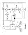
- FIG. 2 is a flow chart diagram 40 of a classifier adaptation method used by the adaptation model update module 26 and the adaptation classifier module 30 .
- the method begins with data element 42 , which is an image patch from the camera 12 , or more specifically, the feature data for any patches selected from an image frame from the camera 12 .
- data element 42 is an image patch from the camera 12 , or more specifically, the feature data for any patches selected from an image frame from the camera 12 .
- the feature data from the data element 42 is processed by the SVM algorithm of the first classifier module 22 , as discussed previously.
- the output of the box 44 is a probability value for each patch, where a probability value near 1 indicates a clear path patch, and a probability value near 0 indicates a non-clear path.
- patches are sorted into high confidence and low confidence groups.
- the current data frame 52 stores the feature data for any patch with a very high clear path probability from the current frame of the camera 12 .
- the data from the current data frame 52 moves to previous data frame 54 , and the new high probability patch data is received in the current data frame 52 .
- This process repeats in real time for the continuous stream of images from the camera 12 .
- a second, higher threshold is applied to patch data from the previous data frame 54 .
- the second threshold could be a probability value greater than 0.95. Patches which do not meet or exceed the threshold value at the decision diamond 56 are discarded at terminus 58 . Patches which meet or exceed the second threshold value at the decision diamond 56 are passed along to data pool 60 .
- the data pool 60 contains clusters of data from previously received patches.
- a consistency value is calculated, which is an indication of how consistent the incoming patch is to the training data in the adaptation model update module 26 .
- the consistency value can be calculated at the box 64 with a weighted function, such as an algebraic sum, a geometric sum, or an exponential sum.
- the consistency value at the box 64 is a weighted algebraic function of the three distances, d_curr, d_prev, and d_pool, where the weights for the current frame and previous frame terms could be assigned a value of 1, and the weight for the pool term could be computed as the counter number for the target cluster divided by the sum of all of the counter numbers for all of the clusters in the data pool 60 .
- the consistency value converts weighted distances—from the incoming patch to each of the elements of stored data contained in the adaptation model update module 26 —into a probability that the incoming patch is a clear path.
- a joint decision is reached for the low-confidence patches, where the joint decision is based upon both the probability value from the first classifier module 22 , and the consistency value from the box 64 in the adaptation classifier module 30 .
- the joint decision value computed at the box 66 could be a simple averaging of the probability value and the consistency value, or it could be a weighted function. For example, more weight could be given to the consistency value from the box 64 , as this value is based on a classifier which is trained with images from the current driving trip.
- a final decision is reached at decision diamond 68 , and each patch is determined either to be a non-clear path at terminus 70 , or a clear path at terminus 72 .
- the purpose and effect of the method shown on the flow chart diagram 40 can be explained as follows.
- patches with a very high probability of being clear path roadway are directed into the adaptation model update module 26 , where they serve as training samples.
- the training sample data contained in the adaptation model update module 26 which is being updated continuously in real time, is used in a second trained classifier in the adaptation classifier module 30 .
- Patches which don't have a very high probability of being clear path roadway are directed through the second trained classifier in the adaptation classifier module 30 .
- the adaptation classifier module 30 may be able to make a better determination of whether a patch represents clear path roadway or not.
- Test data from a prototype system shows that the method does in fact improve the clear path detection accuracy of the system 10 compared to a similar system with only a single, non-adaptive, trained classifier.
- FIG. 4 is a block diagram of a system 100 which can be used for clear path detection, using an adaptive classifier updating strategy implemented via reliable local model updating.
- a single classifier is trained to favor reliable local test samples, where the test samples are local both in terms of space and time.
- the system 100 includes a camera 102 , which is the same type of device and performs the same function as the camera 12 of the system 10 .
- the camera 102 provides an image to a pre-processing module 104 which pre-processes the image.
- the pre-processing module provides the image to a segmentation module 106 which segments the image and provides one or more patches on line 108 to a feature extraction module 110 .
- the operation of the pre-processing module 104 , the segmentation module 106 , and the feature extraction module 110 are the same as described previously for the pre-processing module 14 , the segmentation module 16 , and the feature extraction module 20 of the system 10 . That is, the output of the feature extraction module 110 is a set of characteristic feature data for the patches produced by the segmentation module 106 .
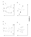
- FIG. 5 is an illustration of two functionally-equivalent SVM training sample sets.
- Training sample set 130 contains a relatively large number of training samples, including positive training samples 132 and negative training samples 134 .
- an SVM classifier boundary 136 can be defined.
- Training sample set 140 contains a reduced number of training samples, including positive training samples 142 and negative training samples 144 .
- the positive training samples 142 are a subset of the positive training samples 132 which are nearest the SVM classifier boundary 136
- the negative training samples 144 are a subset of the negative training samples 134 which are nearest the SVM classifier boundary 136 .
- an SVM classifier boundary 146 can be defined which is identical to the SVM classifier boundary 136 . That is, an SVM classifier boundary is affected only by the training samples nearest the boundary, not by far-field training samples. Since the speed of an SVM classifier is proportional to the number of support vectors included, it follows that the training sample set 140 will result in a classifier of greater speed and equal accuracy, compared to the training sample set 130 .
- a new classifier model 190 can be used to classify the next incoming test samples, using the new SVM classifier boundary 182 .
- the next incoming test samples are classified as, for example, a positive current test sample 192 and a negative current test sample 194 .
- FIG. 7 is a flow chart diagram 200 of a method for adaptation of an SVM classifier using local training samples and reliable local test samples.
- the method begins with data element 202 , which is an image patch from the camera 102 , or more specifically, the feature data for any patches selected from an image frame from the camera 102 .
- the feature data from the data element 202 is provided to box 204 for processing by a classifier, such as an SVM classifier.
- the output of the box 204 is a probability value for each patch, which is used to determine clear path or non-clear path, discussed below, and is also used as input for classifier adaptation.
- a probability value near 1 indicates high confidence of a clear path patch
- a probability value near 0 indicates a high confidence of a non-clear path.
- patches are sorted into high confidence and low confidence groups.
- patches are sorted into those with very high probability and those with very low probability.
- the patches with very low probability of being a clear path patch for example, those with a probability value less than or equal to 0.1, are provided to data store 212 , where they can be used as reliable negative test samples for classifier training, as discussed previously.
- the patches with very high probability of being a clear path patch for example, those patches with a probability exceeding a first threshold value, such as 0.9, are provided to current data frame 214 .
- Previous data frame 216 receives patches from the current data frame 214 whenever a new patch moves into the current data frame 214 .
- patches from the previous data frame 216 are evaluated against a second threshold value, such as 0.95, at decision diamond 218 .
- SVM classifiers may perform better if a kernel function is added. Rather than fitting nonlinear curves to complex data, SVM classifiers can handle the complexity by using a kernel function to map the data into a different space where a hyperplane can be used to separate the data into classes.
- a powerful and commonly-used kernel function is the Radial Basis Function (RBF), which is a real-valued function whose value depends only on the distance from an origin or some other point called a center.
- RBF Radial Basis Function
- the notation exp ( . . . ) designates the natural logarithm base e raised to the power of the value in parenthesis.
- FIG. 8 is a flow chart diagram 300 of an alternate embodiment of a classifier adaptation method which can be used by the system of FIG. 4 .
- the classifier at the box 204 is used to classify all patch data for clear path or non-clear path determination, as before.
- the classifier at the box 204 is not used to determine which patches are reliable enough for adaptive classifier training. Instead, another classifier is added at box 302 .
- the classifier at the box 302 is adaptively trained only by data from the nearby training support vector data store 226 and the regions-passed data store 236 . That is, the classifier at the box 302 is not affected by the local test support vectors from the box 228 .
Landscapes
- Engineering & Computer Science (AREA)
- Physics & Mathematics (AREA)
- General Physics & Mathematics (AREA)
- Multimedia (AREA)
- Theoretical Computer Science (AREA)
- Image Analysis (AREA)
- Traffic Control Systems (AREA)
Abstract
Description
K(x,c)=exp(−γ∥x−c∥ 2) (1)
Where K is the kernel function, x is the feature vector being evaluated, c is the RBF center, which is the training feature vector being used, and γ is a constant. The notation exp ( . . . ) designates the natural logarithm base e raised to the power of the value in parenthesis.
Claims (18)
Priority Applications (3)
| Application Number | Priority Date | Filing Date | Title |
|---|---|---|---|
| US12/963,404 US8773535B2 (en) | 2010-12-08 | 2010-12-08 | Adaptation for clear path detection using reliable local model updating |
| DE102011055458A DE102011055458A1 (en) | 2010-12-08 | 2011-11-17 | Adaptation technology for the detection of a free lane by means of reliable local model calibration |
| CN201110405567.3A CN102693432B (en) | 2010-12-08 | 2011-12-08 | Use reliable partial model more to newly arrive and regulate clear path to detect |
Applications Claiming Priority (1)
| Application Number | Priority Date | Filing Date | Title |
|---|---|---|---|
| US12/963,404 US8773535B2 (en) | 2010-12-08 | 2010-12-08 | Adaptation for clear path detection using reliable local model updating |
Publications (2)
| Publication Number | Publication Date |
|---|---|
| US20120147189A1 US20120147189A1 (en) | 2012-06-14 |
| US8773535B2 true US8773535B2 (en) | 2014-07-08 |
Family
ID=46144752
Family Applications (1)
| Application Number | Title | Priority Date | Filing Date |
|---|---|---|---|
| US12/963,404 Active 2032-05-18 US8773535B2 (en) | 2010-12-08 | 2010-12-08 | Adaptation for clear path detection using reliable local model updating |
Country Status (3)
| Country | Link |
|---|---|
| US (1) | US8773535B2 (en) |
| CN (1) | CN102693432B (en) |
| DE (1) | DE102011055458A1 (en) |
Cited By (5)
| Publication number | Priority date | Publication date | Assignee | Title |
|---|---|---|---|---|
| US20150030238A1 (en) * | 2013-07-29 | 2015-01-29 | Adobe Systems Incorporated | Visual pattern recognition in an image |
| US20160121912A1 (en) * | 2013-11-27 | 2016-05-05 | Solfice Research, Inc. | Real time machine vision system for train control and protection |
| US10762360B2 (en) | 2018-11-19 | 2020-09-01 | Waymo Llc | Automatically detecting unmapped drivable road surfaces for autonomous vehicles |
| US11417117B2 (en) | 2017-09-22 | 2022-08-16 | Continental Teves Ag & Co. Ohg | Method and device for detecting lanes, driver assistance system and vehicle |
| US11945478B2 (en) | 2019-11-20 | 2024-04-02 | Ground Transportation Systems Canada Inc. | High-integrity object detection system and method |
Families Citing this family (27)
| Publication number | Priority date | Publication date | Assignee | Title |
|---|---|---|---|---|
| US8773535B2 (en) * | 2010-12-08 | 2014-07-08 | GM Global Technology Operations LLC | Adaptation for clear path detection using reliable local model updating |
| US9589184B1 (en) | 2012-08-16 | 2017-03-07 | Groupon, Inc. | Method, apparatus, and computer program product for classification of documents |
| CN103324955A (en) * | 2013-06-14 | 2013-09-25 | 浙江智尔信息技术有限公司 | Pedestrian detection method based on video processing |
| CN103810504B (en) * | 2014-01-14 | 2017-03-22 | 三星电子(中国)研发中心 | Image processing method and device |
| CN104392228B (en) * | 2014-12-19 | 2018-01-26 | 中国人民解放军国防科学技术大学 | Target class detection method in UAV images based on conditional random field model |
| GB2550523A (en) * | 2015-02-02 | 2017-11-22 | Beijing Didi Infinity Tech And Dev Co Ltd | Methods and systems for order processing |
| CN105989334B (en) * | 2015-02-12 | 2020-11-17 | 中国科学院西安光学精密机械研究所 | Road detection method based on monocular vision |
| CN105022990B (en) * | 2015-06-29 | 2018-09-21 | 华中科技大学 | A kind of waterborne target rapid detection method based on unmanned boat application |
| US9606539B1 (en) | 2015-11-04 | 2017-03-28 | Zoox, Inc. | Autonomous vehicle fleet service and system |
| US9632502B1 (en) * | 2015-11-04 | 2017-04-25 | Zoox, Inc. | Machine-learning systems and techniques to optimize teleoperation and/or planner decisions |
| US12265386B2 (en) | 2015-11-04 | 2025-04-01 | Zoox, Inc. | Autonomous vehicle fleet service and system |
| US10401852B2 (en) | 2015-11-04 | 2019-09-03 | Zoox, Inc. | Teleoperation system and method for trajectory modification of autonomous vehicles |
| WO2017079341A2 (en) | 2015-11-04 | 2017-05-11 | Zoox, Inc. | Automated extraction of semantic information to enhance incremental mapping modifications for robotic vehicles |
| US11023788B2 (en) * | 2016-01-05 | 2021-06-01 | Mobileye Vision Technologies Ltd. | Systems and methods for estimating future paths |
| CN106228134A (en) * | 2016-07-21 | 2016-12-14 | 北京奇虎科技有限公司 | Drivable region detection method based on pavement image, Apparatus and system |
| KR101792442B1 (en) * | 2016-12-12 | 2017-10-31 | 삼성전기주식회사 | Electronic module and manufacturing method thereof |
| US10255525B1 (en) * | 2017-04-25 | 2019-04-09 | Uber Technologies, Inc. | FPGA device for image classification |
| WO2018209057A1 (en) | 2017-05-11 | 2018-11-15 | The Research Foundation For The State University Of New York | System and method associated with predicting segmentation quality of objects in analysis of copious image data |
| US10769788B2 (en) * | 2017-09-12 | 2020-09-08 | Nantomics, Llc | Few-shot learning based image recognition of whole slide image at tissue level |
| JP6897597B2 (en) * | 2018-02-16 | 2021-06-30 | トヨタ自動車株式会社 | Parking support device |
| CN109583482B (en) * | 2018-11-13 | 2022-08-16 | 河海大学 | Infrared human body target image identification method based on multi-feature fusion and multi-kernel transfer learning |
| CN110929739B (en) * | 2019-11-21 | 2023-03-24 | 成都理工大学 | Automatic impervious surface range remote sensing iterative extraction method |
| US12112555B1 (en) | 2024-04-12 | 2024-10-08 | Samsara Inc. | Drowsy driving detection |
| US12165393B1 (en) | 2024-04-23 | 2024-12-10 | Samsara Inc. | Lane departure monitoring |
| US12263861B1 (en) | 2024-05-15 | 2025-04-01 | Samsara Inc. | Automatic training assignment based on operator behavior |
| US12266123B1 (en) | 2024-05-23 | 2025-04-01 | Samsara Inc. | Monitoring the safe distance between vehicles while driving |
| US12272138B1 (en) * | 2024-06-21 | 2025-04-08 | Samsara Inc. | Forward collision warning |
Citations (50)
| Publication number | Priority date | Publication date | Assignee | Title |
|---|---|---|---|---|
| US5486819A (en) * | 1990-11-27 | 1996-01-23 | Matsushita Electric Industrial Co., Ltd. | Road obstacle monitoring device |
| US5642093A (en) * | 1995-01-27 | 1997-06-24 | Fuji Jukogyo Kabushiki Kaisha | Warning system for vehicle |
| US20010045981A1 (en) * | 2000-05-24 | 2001-11-29 | Joachim Gloger | Camera-based precrash detection system |
| US20040183906A1 (en) * | 2003-03-20 | 2004-09-23 | Nobuharu Nagaoka | Device for monitoring around vehicle |
| US6813370B1 (en) * | 1999-09-22 | 2004-11-02 | Fuji Jukogyo Kabushiki Kaisha | Lane marker recognizing apparatus |
| US20050192727A1 (en) * | 1994-05-09 | 2005-09-01 | Automotive Technologies International Inc. | Sensor Assemblies |
| US20050278098A1 (en) * | 1994-05-23 | 2005-12-15 | Automotive Technologies International, Inc. | Vehicular impact reactive system and method |
| US7089099B2 (en) * | 2004-07-30 | 2006-08-08 | Automotive Technologies International, Inc. | Sensor assemblies |
| US20070005202A1 (en) * | 1995-06-07 | 2007-01-04 | Automotive Technologies International, Inc. | Remote Vehicle Diagnostic Management |
| US20070008182A1 (en) * | 2005-06-08 | 2007-01-11 | Denso Corporation | Image processing device for vehicle |
| US20070021915A1 (en) * | 1997-10-22 | 2007-01-25 | Intelligent Technologies International, Inc. | Collision Avoidance Methods and Systems |
| US20070024467A1 (en) * | 2005-07-28 | 2007-02-01 | Fujitsu Limited | Roadway type judgment method and apparatus |
| US20070109111A1 (en) * | 1997-10-22 | 2007-05-17 | Intelligent Technologies International, Inc. | Accident Avoidance Systems and Methods |
| US20070152804A1 (en) * | 1997-10-22 | 2007-07-05 | Intelligent Technologies International, Inc. | Accident Avoidance Systems and Methods |
| US20070257819A1 (en) * | 2006-05-05 | 2007-11-08 | Eis Electronic Integrated Systems Inc. | Traffic sensor incorporating a video camera and method of operating same |
| US20080040004A1 (en) * | 1994-05-23 | 2008-02-14 | Automotive Technologies International, Inc. | System and Method for Preventing Vehicular Accidents |
| US20080046150A1 (en) * | 1994-05-23 | 2008-02-21 | Automotive Technologies International, Inc. | System and Method for Detecting and Protecting Pedestrians |
| US20080240500A1 (en) * | 2007-04-02 | 2008-10-02 | Industrial Technology Research Institute | Image processing methods |
| US20090256911A1 (en) * | 2005-09-23 | 2009-10-15 | A-Hamid Hakki | System and method for traffic related information display, traffic surveillance and control |
| US20090268948A1 (en) * | 2008-04-24 | 2009-10-29 | Gm Global Technology Operations, Inc. | Pixel-based texture-rich clear path detection |
| US20090268946A1 (en) * | 2008-04-24 | 2009-10-29 | Gm Global Technology Operations, Inc. | Vehicle clear path detection |
| US20090290032A1 (en) * | 2008-05-22 | 2009-11-26 | Gm Global Technology Operations, Inc. | Self calibration of extrinsic camera parameters for a vehicle camera |
| US20090295917A1 (en) * | 2008-04-24 | 2009-12-03 | Gm Global Technology Operations, Inc. | Pixel-based texture-less clear path detection |
| US20100014713A1 (en) * | 2008-07-18 | 2010-01-21 | Gm Global Technology Operations, Inc. | Road-lane marker detection |
| US20100017060A1 (en) * | 2008-07-18 | 2010-01-21 | Gm Global Technology Operations, Inc. | Road-edge detection |
| US20100014714A1 (en) * | 2008-07-18 | 2010-01-21 | Gm Global Technology Operations, Inc. | Camera-based lane marker detection |
| US20100097457A1 (en) * | 2008-04-24 | 2010-04-22 | Gm Global Technology Opetations, Inc. | Clear path detection with patch smoothing approach |
| US20100097458A1 (en) * | 2008-04-24 | 2010-04-22 | Gm Global Technology Operations, Inc. | Clear path detection using an example-based approach |
| US20100100268A1 (en) * | 2008-04-24 | 2010-04-22 | Gm Global Technology Operations, Inc. | Enhanced clear path detection in the presence of traffic infrastructure indicator |
| US20100097455A1 (en) * | 2008-04-24 | 2010-04-22 | Gm Global Technology Operations, Inc | Clear path detection using a vanishing point |
| US20100097456A1 (en) * | 2008-04-24 | 2010-04-22 | Gm Global Technology Operations, Inc. | Clear path detection using a hierachical approach |
| US20100098297A1 (en) * | 2008-04-24 | 2010-04-22 | Gm Global Technology Operations, Inc. | Clear path detection using segmentation-based method |
| US20100098290A1 (en) * | 2008-04-24 | 2010-04-22 | Gm Global Technology Operations, Inc. | Method for detecting a clear path through topographical variation analysis |
| US20100104137A1 (en) * | 2008-04-24 | 2010-04-29 | Gm Global Technology Operations, Inc. | Clear path detection using patch approach |
| US20100104199A1 (en) * | 2008-04-24 | 2010-04-29 | Gm Global Technology Operations, Inc. | Method for detecting a clear path of travel for a vehicle enhanced by object detection |
| US20100121577A1 (en) * | 2008-04-24 | 2010-05-13 | Gm Global Technology Operations, Inc. | Three-dimensional lidar-based clear path detection |
| US20100131197A1 (en) * | 2008-11-21 | 2010-05-27 | Gm Global Technology Operations, Inc. | Visual guidance for vehicle navigation system |
| US20100201814A1 (en) * | 2009-02-06 | 2010-08-12 | Gm Global Technology Operations, Inc. | Camera auto-calibration by horizon estimation |
| US20100276962A1 (en) * | 2009-04-29 | 2010-11-04 | Gm Global Technology Operations, Inc. | Active face shade detection in auto sun-shade system |
| US20110133510A1 (en) * | 2009-12-07 | 2011-06-09 | Gm Global Technology Operations, Inc. | Saturation-based shade-line detection |
| US20110221901A1 (en) * | 2010-03-11 | 2011-09-15 | Gm Global Technology Operations, Inc. | Adaptive Scene Rendering and V2X Video/Image Sharing |
| US8050459B2 (en) * | 2008-07-25 | 2011-11-01 | GM Global Technology Operations LLC | System and method for detecting pedestrians |
| US20110304444A1 (en) * | 2010-06-15 | 2011-12-15 | Gm Global Technology Operations, Inc. | Portable vision system |
| US20120008021A1 (en) * | 2010-07-06 | 2012-01-12 | Gm Global Technology Operations, Inc. | Shadow Removal in an Image Captured by a Vehicle-Based Camera for Clear Path Detection |
| US20120008019A1 (en) * | 2010-07-06 | 2012-01-12 | Gm Global Technology Operations, Inc. | Shadow Removal in an Image Captured by a Vehicle-Based Camera Using an Optimized Oriented Linear Axis |
| US20120008020A1 (en) * | 2010-07-06 | 2012-01-12 | Gm Global Technology Operations, Inc. | Shadow Removal in an Image Captured by a Vehicle Based Camera Using a Non-Linear Illumination-Invariant Kernel |
| US20120116676A1 (en) * | 2010-11-10 | 2012-05-10 | Gm Global Technology Operations, Inc. | Method of Augmenting GPS or GPS/Sensor Vehicle Positioning Using Additional In-Vehicle Vision Sensors |
| US20120147176A1 (en) * | 2010-12-08 | 2012-06-14 | GM Global Technology Operations LLC | Adaptation for clear path detection with additional classifiers |
| US20120147189A1 (en) * | 2010-12-08 | 2012-06-14 | GM Global Technology Operations LLC | Adaptation for clear path detection using reliable local model updating |
| US8315766B2 (en) * | 2007-10-31 | 2012-11-20 | Valeo Vision | Process for detecting a phenomenon limiting the visibility for a motor vehicle |
Family Cites Families (1)
| Publication number | Priority date | Publication date | Assignee | Title |
|---|---|---|---|---|
| US8699754B2 (en) * | 2008-04-24 | 2014-04-15 | GM Global Technology Operations LLC | Clear path detection through road modeling |
-
2010
- 2010-12-08 US US12/963,404 patent/US8773535B2/en active Active
-
2011
- 2011-11-17 DE DE102011055458A patent/DE102011055458A1/en not_active Withdrawn
- 2011-12-08 CN CN201110405567.3A patent/CN102693432B/en not_active Expired - Fee Related
Patent Citations (62)
| Publication number | Priority date | Publication date | Assignee | Title |
|---|---|---|---|---|
| US5486819A (en) * | 1990-11-27 | 1996-01-23 | Matsushita Electric Industrial Co., Ltd. | Road obstacle monitoring device |
| US20050192727A1 (en) * | 1994-05-09 | 2005-09-01 | Automotive Technologies International Inc. | Sensor Assemblies |
| US20080040004A1 (en) * | 1994-05-23 | 2008-02-14 | Automotive Technologies International, Inc. | System and Method for Preventing Vehicular Accidents |
| US7359782B2 (en) * | 1994-05-23 | 2008-04-15 | Automotive Technologies International, Inc. | Vehicular impact reactive system and method |
| US20080046150A1 (en) * | 1994-05-23 | 2008-02-21 | Automotive Technologies International, Inc. | System and Method for Detecting and Protecting Pedestrians |
| US20050278098A1 (en) * | 1994-05-23 | 2005-12-15 | Automotive Technologies International, Inc. | Vehicular impact reactive system and method |
| US7630806B2 (en) * | 1994-05-23 | 2009-12-08 | Automotive Technologies International, Inc. | System and method for detecting and protecting pedestrians |
| US5642093A (en) * | 1995-01-27 | 1997-06-24 | Fuji Jukogyo Kabushiki Kaisha | Warning system for vehicle |
| US20070005202A1 (en) * | 1995-06-07 | 2007-01-04 | Automotive Technologies International, Inc. | Remote Vehicle Diagnostic Management |
| US20070109111A1 (en) * | 1997-10-22 | 2007-05-17 | Intelligent Technologies International, Inc. | Accident Avoidance Systems and Methods |
| US20070152804A1 (en) * | 1997-10-22 | 2007-07-05 | Intelligent Technologies International, Inc. | Accident Avoidance Systems and Methods |
| US20070021915A1 (en) * | 1997-10-22 | 2007-01-25 | Intelligent Technologies International, Inc. | Collision Avoidance Methods and Systems |
| US20090033540A1 (en) * | 1997-10-22 | 2009-02-05 | Intelligent Technologies International, Inc. | Accident Avoidance Systems and Methods |
| US6813370B1 (en) * | 1999-09-22 | 2004-11-02 | Fuji Jukogyo Kabushiki Kaisha | Lane marker recognizing apparatus |
| US6838980B2 (en) * | 2000-05-24 | 2005-01-04 | Daimlerchrysler Ag | Camera-based precrash detection system |
| US20010045981A1 (en) * | 2000-05-24 | 2001-11-29 | Joachim Gloger | Camera-based precrash detection system |
| US7330568B2 (en) * | 2003-03-20 | 2008-02-12 | Honda Motor Co., Ltd. | Device for monitoring around vehicle |
| US20040183906A1 (en) * | 2003-03-20 | 2004-09-23 | Nobuharu Nagaoka | Device for monitoring around vehicle |
| US7089099B2 (en) * | 2004-07-30 | 2006-08-08 | Automotive Technologies International, Inc. | Sensor assemblies |
| US20070008182A1 (en) * | 2005-06-08 | 2007-01-11 | Denso Corporation | Image processing device for vehicle |
| US20070024467A1 (en) * | 2005-07-28 | 2007-02-01 | Fujitsu Limited | Roadway type judgment method and apparatus |
| US20090256911A1 (en) * | 2005-09-23 | 2009-10-15 | A-Hamid Hakki | System and method for traffic related information display, traffic surveillance and control |
| US20070257819A1 (en) * | 2006-05-05 | 2007-11-08 | Eis Electronic Integrated Systems Inc. | Traffic sensor incorporating a video camera and method of operating same |
| US20080240500A1 (en) * | 2007-04-02 | 2008-10-02 | Industrial Technology Research Institute | Image processing methods |
| US7929729B2 (en) * | 2007-04-02 | 2011-04-19 | Industrial Technology Research Institute | Image processing methods |
| US8315766B2 (en) * | 2007-10-31 | 2012-11-20 | Valeo Vision | Process for detecting a phenomenon limiting the visibility for a motor vehicle |
| US20100097458A1 (en) * | 2008-04-24 | 2010-04-22 | Gm Global Technology Operations, Inc. | Clear path detection using an example-based approach |
| US20100098297A1 (en) * | 2008-04-24 | 2010-04-22 | Gm Global Technology Operations, Inc. | Clear path detection using segmentation-based method |
| US20090295917A1 (en) * | 2008-04-24 | 2009-12-03 | Gm Global Technology Operations, Inc. | Pixel-based texture-less clear path detection |
| US20100121577A1 (en) * | 2008-04-24 | 2010-05-13 | Gm Global Technology Operations, Inc. | Three-dimensional lidar-based clear path detection |
| US20100104199A1 (en) * | 2008-04-24 | 2010-04-29 | Gm Global Technology Operations, Inc. | Method for detecting a clear path of travel for a vehicle enhanced by object detection |
| US20100097457A1 (en) * | 2008-04-24 | 2010-04-22 | Gm Global Technology Opetations, Inc. | Clear path detection with patch smoothing approach |
| US20090268946A1 (en) * | 2008-04-24 | 2009-10-29 | Gm Global Technology Operations, Inc. | Vehicle clear path detection |
| US20100100268A1 (en) * | 2008-04-24 | 2010-04-22 | Gm Global Technology Operations, Inc. | Enhanced clear path detection in the presence of traffic infrastructure indicator |
| US20100097455A1 (en) * | 2008-04-24 | 2010-04-22 | Gm Global Technology Operations, Inc | Clear path detection using a vanishing point |
| US20100097456A1 (en) * | 2008-04-24 | 2010-04-22 | Gm Global Technology Operations, Inc. | Clear path detection using a hierachical approach |
| US20090268948A1 (en) * | 2008-04-24 | 2009-10-29 | Gm Global Technology Operations, Inc. | Pixel-based texture-rich clear path detection |
| US20100098290A1 (en) * | 2008-04-24 | 2010-04-22 | Gm Global Technology Operations, Inc. | Method for detecting a clear path through topographical variation analysis |
| US20100104137A1 (en) * | 2008-04-24 | 2010-04-29 | Gm Global Technology Operations, Inc. | Clear path detection using patch approach |
| US20090290032A1 (en) * | 2008-05-22 | 2009-11-26 | Gm Global Technology Operations, Inc. | Self calibration of extrinsic camera parameters for a vehicle camera |
| US20100017060A1 (en) * | 2008-07-18 | 2010-01-21 | Gm Global Technology Operations, Inc. | Road-edge detection |
| US8194927B2 (en) * | 2008-07-18 | 2012-06-05 | GM Global Technology Operations LLC | Road-lane marker detection using light-based sensing technology |
| US8204277B2 (en) * | 2008-07-18 | 2012-06-19 | GM Global Technology Operations LLC | Apparatus and method for camera-bases lane marker detection |
| US8099213B2 (en) * | 2008-07-18 | 2012-01-17 | GM Global Technology Operations LLC | Road-edge detection |
| US20100014714A1 (en) * | 2008-07-18 | 2010-01-21 | Gm Global Technology Operations, Inc. | Camera-based lane marker detection |
| US20100014713A1 (en) * | 2008-07-18 | 2010-01-21 | Gm Global Technology Operations, Inc. | Road-lane marker detection |
| US8050459B2 (en) * | 2008-07-25 | 2011-11-01 | GM Global Technology Operations LLC | System and method for detecting pedestrians |
| US20100131197A1 (en) * | 2008-11-21 | 2010-05-27 | Gm Global Technology Operations, Inc. | Visual guidance for vehicle navigation system |
| US8259174B2 (en) * | 2009-02-06 | 2012-09-04 | GM Global Technology Operations LLC | Camera auto-calibration by horizon estimation |
| US20100201814A1 (en) * | 2009-02-06 | 2010-08-12 | Gm Global Technology Operations, Inc. | Camera auto-calibration by horizon estimation |
| US20100276962A1 (en) * | 2009-04-29 | 2010-11-04 | Gm Global Technology Operations, Inc. | Active face shade detection in auto sun-shade system |
| US20110133510A1 (en) * | 2009-12-07 | 2011-06-09 | Gm Global Technology Operations, Inc. | Saturation-based shade-line detection |
| US20110221901A1 (en) * | 2010-03-11 | 2011-09-15 | Gm Global Technology Operations, Inc. | Adaptive Scene Rendering and V2X Video/Image Sharing |
| US20110304444A1 (en) * | 2010-06-15 | 2011-12-15 | Gm Global Technology Operations, Inc. | Portable vision system |
| US20120008020A1 (en) * | 2010-07-06 | 2012-01-12 | Gm Global Technology Operations, Inc. | Shadow Removal in an Image Captured by a Vehicle Based Camera Using a Non-Linear Illumination-Invariant Kernel |
| US20120008019A1 (en) * | 2010-07-06 | 2012-01-12 | Gm Global Technology Operations, Inc. | Shadow Removal in an Image Captured by a Vehicle-Based Camera Using an Optimized Oriented Linear Axis |
| US8294794B2 (en) * | 2010-07-06 | 2012-10-23 | GM Global Technology Operations LLC | Shadow removal in an image captured by a vehicle-based camera for clear path detection |
| US20120008021A1 (en) * | 2010-07-06 | 2012-01-12 | Gm Global Technology Operations, Inc. | Shadow Removal in an Image Captured by a Vehicle-Based Camera for Clear Path Detection |
| US8319854B2 (en) * | 2010-07-06 | 2012-11-27 | GM Global Technology Operations LLC | Shadow removal in an image captured by a vehicle based camera using a non-linear illumination-invariant kernel |
| US20120116676A1 (en) * | 2010-11-10 | 2012-05-10 | Gm Global Technology Operations, Inc. | Method of Augmenting GPS or GPS/Sensor Vehicle Positioning Using Additional In-Vehicle Vision Sensors |
| US20120147176A1 (en) * | 2010-12-08 | 2012-06-14 | GM Global Technology Operations LLC | Adaptation for clear path detection with additional classifiers |
| US20120147189A1 (en) * | 2010-12-08 | 2012-06-14 | GM Global Technology Operations LLC | Adaptation for clear path detection using reliable local model updating |
Non-Patent Citations (2)
| Title |
|---|
| Qi Wu, Wende Zhang, Tsuhan Chen, B.V.K.V. Kumar, Camera-based clear path detection, 2010 IEEE International Conference on Acoustics Speech and Signal Processing (ICASSP), Dallas, TX, Mar. 2010. |
| Xiaoming Liu, Tsuhan Chen, Susan M. Thornton, Eigenspace updating for non-stationary process and its application to face recognition, Pattern Recognition, vol. 38, Issue 9, Kernel and Subspace Methods for Computer Vision, Sep. 2003, pp. 1945-1959. |
Cited By (9)
| Publication number | Priority date | Publication date | Assignee | Title |
|---|---|---|---|---|
| US20150030238A1 (en) * | 2013-07-29 | 2015-01-29 | Adobe Systems Incorporated | Visual pattern recognition in an image |
| US9141885B2 (en) * | 2013-07-29 | 2015-09-22 | Adobe Systems Incorporated | Visual pattern recognition in an image |
| US20160121912A1 (en) * | 2013-11-27 | 2016-05-05 | Solfice Research, Inc. | Real time machine vision system for train control and protection |
| US10086857B2 (en) * | 2013-11-27 | 2018-10-02 | Shanmukha Sravan Puttagunta | Real time machine vision system for train control and protection |
| US20180370552A1 (en) * | 2013-11-27 | 2018-12-27 | Solfice Research, Inc. | Real time machine vision system for vehicle control and protection |
| US11417117B2 (en) | 2017-09-22 | 2022-08-16 | Continental Teves Ag & Co. Ohg | Method and device for detecting lanes, driver assistance system and vehicle |
| US10762360B2 (en) | 2018-11-19 | 2020-09-01 | Waymo Llc | Automatically detecting unmapped drivable road surfaces for autonomous vehicles |
| US11373419B2 (en) | 2018-11-19 | 2022-06-28 | Waymo Llc | Automatically detecting unmapped drivable road surfaces for autonomous vehicles |
| US11945478B2 (en) | 2019-11-20 | 2024-04-02 | Ground Transportation Systems Canada Inc. | High-integrity object detection system and method |
Also Published As
| Publication number | Publication date |
|---|---|
| CN102693432B (en) | 2015-12-02 |
| US20120147189A1 (en) | 2012-06-14 |
| CN102693432A (en) | 2012-09-26 |
| DE102011055458A1 (en) | 2012-06-14 |
Similar Documents
| Publication | Publication Date | Title |
|---|---|---|
| US8773535B2 (en) | Adaptation for clear path detection using reliable local model updating | |
| US8681222B2 (en) | Adaptation for clear path detection with additional classifiers | |
| Zakaria et al. | Lane detection in autonomous vehicles: A systematic review | |
| Khammari et al. | Vehicle detection combining gradient analysis and AdaBoost classification | |
| Kuang et al. | Combining region-of-interest extraction and image enhancement for nighttime vehicle detection | |
| US20210089794A1 (en) | Vehicle system and method for detecting objects and object distance | |
| Guo et al. | Nighttime vehicle lamp detection and tracking with adaptive mask training | |
| CN101950350A (en) | Clear path detection using a hierachical approach | |
| Cui et al. | Vehicle localisation using a single camera | |
| Magnussen et al. | A survey of the inadequacies in traffic sign recognition systems for autonomous vehicles | |
| CN114898306B (en) | Method and device for detecting target orientation and electronic equipment | |
| CN117710918A (en) | Lane line detection method and system | |
| Helala et al. | Road boundary detection in challenging scenarios | |
| EP3591956A1 (en) | Device for determining camera blockage | |
| Klammsteiner et al. | Vision based stationary railway track monitoring system | |
| Tseng et al. | Blind-spot vehicle detection using motion and static features | |
| Pavitha et al. | RIOD: Reinforced image-based object detection for unruly weather conditions | |
| Tourani et al. | Challenges of video-based vehicle detection and tracking in intelligent transportation systems | |
| Huang et al. | Nighttime vehicle detection and tracking base on spatiotemporal analysis using RCCC sensor | |
| ApinayaPrethi et al. | Fog detection and visibility measurement using SVM | |
| Yoshimori et al. | License plate detection system in rainy days | |
| Kumar | Vehicle detection in monocular night-time grey-level videos | |
| Paul et al. | Application of the SNoW machine learning paradigm to a set of transportation imaging problems | |
| Khac et al. | Detection of abnormal moving vehicles for intelligent driver assistance system | |
| Murase | Image recognition for driver assistance in intelligent vehicles |
Legal Events
| Date | Code | Title | Description |
|---|---|---|---|
| AS | Assignment |
Owner name: GM GLOBAL TECHNOLOGY OPERATIONS LLC, MICHIGAN Free format text: ASSIGNMENT OF ASSIGNORS INTEREST;ASSIGNOR:ZHANG, WENDE;REEL/FRAME:025467/0970 Effective date: 20101201 |
|
| AS | Assignment |
Owner name: WILMINGTON TRUST COMPANY, DELAWARE Free format text: SECURITY AGREEMENT;ASSIGNOR:GM GLOBAL TECHNOLOGY OPERATIONS LLC;REEL/FRAME:026499/0267 Effective date: 20101027 |
|
| FEPP | Fee payment procedure |
Free format text: PAYOR NUMBER ASSIGNED (ORIGINAL EVENT CODE: ASPN); ENTITY STATUS OF PATENT OWNER: LARGE ENTITY |
|
| STCF | Information on status: patent grant |
Free format text: PATENTED CASE |
|
| AS | Assignment |
Owner name: GM GLOBAL TECHNOLOGY OPERATIONS LLC, MICHIGAN Free format text: RELEASE BY SECURED PARTY;ASSIGNOR:WILMINGTON TRUST COMPANY;REEL/FRAME:034287/0159 Effective date: 20141017 |
|
| MAFP | Maintenance fee payment |
Free format text: PAYMENT OF MAINTENANCE FEE, 4TH YEAR, LARGE ENTITY (ORIGINAL EVENT CODE: M1551) Year of fee payment: 4 |
|
| MAFP | Maintenance fee payment |
Free format text: PAYMENT OF MAINTENANCE FEE, 8TH YEAR, LARGE ENTITY (ORIGINAL EVENT CODE: M1552); ENTITY STATUS OF PATENT OWNER: LARGE ENTITY Year of fee payment: 8 |
|
| MAFP | Maintenance fee payment |
Free format text: PAYMENT OF MAINTENANCE FEE, 12TH YEAR, LARGE ENTITY (ORIGINAL EVENT CODE: M1553); ENTITY STATUS OF PATENT OWNER: LARGE ENTITY Year of fee payment: 12 |