EP1085280A1 - Dispositif de fusion et division de flux et echangeur thermique faisant appel a ce dispositif - Google Patents
Dispositif de fusion et division de flux et echangeur thermique faisant appel a ce dispositif Download PDFInfo
- Publication number
- EP1085280A1 EP1085280A1 EP99919631A EP99919631A EP1085280A1 EP 1085280 A1 EP1085280 A1 EP 1085280A1 EP 99919631 A EP99919631 A EP 99919631A EP 99919631 A EP99919631 A EP 99919631A EP 1085280 A1 EP1085280 A1 EP 1085280A1
- Authority
- EP
- European Patent Office
- Prior art keywords
- refrigerant
- merging
- flow
- dividing device
- dividing
- Prior art date
- Legal status (The legal status is an assumption and is not a legal conclusion. Google has not performed a legal analysis and makes no representation as to the accuracy of the status listed.)
- Granted
Links
Images


Classifications
-
- F—MECHANICAL ENGINEERING; LIGHTING; HEATING; WEAPONS; BLASTING
- F25—REFRIGERATION OR COOLING; COMBINED HEATING AND REFRIGERATION SYSTEMS; HEAT PUMP SYSTEMS; MANUFACTURE OR STORAGE OF ICE; LIQUEFACTION SOLIDIFICATION OF GASES
- F25B—REFRIGERATION MACHINES, PLANTS OR SYSTEMS; COMBINED HEATING AND REFRIGERATION SYSTEMS; HEAT PUMP SYSTEMS
- F25B39/00—Evaporators; Condensers
- F25B39/02—Evaporators
- F25B39/028—Evaporators having distributing means
-
- F—MECHANICAL ENGINEERING; LIGHTING; HEATING; WEAPONS; BLASTING
- F25—REFRIGERATION OR COOLING; COMBINED HEATING AND REFRIGERATION SYSTEMS; HEAT PUMP SYSTEMS; MANUFACTURE OR STORAGE OF ICE; LIQUEFACTION SOLIDIFICATION OF GASES
- F25B—REFRIGERATION MACHINES, PLANTS OR SYSTEMS; COMBINED HEATING AND REFRIGERATION SYSTEMS; HEAT PUMP SYSTEMS
- F25B41/00—Fluid-circulation arrangements
-
- F—MECHANICAL ENGINEERING; LIGHTING; HEATING; WEAPONS; BLASTING
- F24—HEATING; RANGES; VENTILATING
- F24F—AIR-CONDITIONING; AIR-HUMIDIFICATION; VENTILATION; USE OF AIR CURRENTS FOR SCREENING
- F24F1/00—Room units for air-conditioning, e.g. separate or self-contained units or units receiving primary air from a central station
- F24F1/0007—Indoor units, e.g. fan coil units
- F24F1/0059—Indoor units, e.g. fan coil units characterised by heat exchangers
- F24F1/0067—Indoor units, e.g. fan coil units characterised by heat exchangers by the shape of the heat exchangers or of parts thereof, e.g. of their fins
-
- F—MECHANICAL ENGINEERING; LIGHTING; HEATING; WEAPONS; BLASTING
- F25—REFRIGERATION OR COOLING; COMBINED HEATING AND REFRIGERATION SYSTEMS; HEAT PUMP SYSTEMS; MANUFACTURE OR STORAGE OF ICE; LIQUEFACTION SOLIDIFICATION OF GASES
- F25B—REFRIGERATION MACHINES, PLANTS OR SYSTEMS; COMBINED HEATING AND REFRIGERATION SYSTEMS; HEAT PUMP SYSTEMS
- F25B41/00—Fluid-circulation arrangements
- F25B41/40—Fluid line arrangements
- F25B41/42—Arrangements for diverging or converging flows, e.g. branch lines or junctions
-
- F—MECHANICAL ENGINEERING; LIGHTING; HEATING; WEAPONS; BLASTING
- F28—HEAT EXCHANGE IN GENERAL
- F28F—DETAILS OF HEAT-EXCHANGE AND HEAT-TRANSFER APPARATUS, OF GENERAL APPLICATION
- F28F2210/00—Heat exchange conduits
- F28F2210/02—Heat exchange conduits with particular branching, e.g. fractal conduit arrangements
-
- Y—GENERAL TAGGING OF NEW TECHNOLOGICAL DEVELOPMENTS; GENERAL TAGGING OF CROSS-SECTIONAL TECHNOLOGIES SPANNING OVER SEVERAL SECTIONS OF THE IPC; TECHNICAL SUBJECTS COVERED BY FORMER USPC CROSS-REFERENCE ART COLLECTIONS [XRACs] AND DIGESTS
- Y10—TECHNICAL SUBJECTS COVERED BY FORMER USPC
- Y10T—TECHNICAL SUBJECTS COVERED BY FORMER US CLASSIFICATION
- Y10T137/00—Fluid handling
- Y10T137/8593—Systems
- Y10T137/85938—Non-valved flow dividers
-
- Y—GENERAL TAGGING OF NEW TECHNOLOGICAL DEVELOPMENTS; GENERAL TAGGING OF CROSS-SECTIONAL TECHNOLOGIES SPANNING OVER SEVERAL SECTIONS OF THE IPC; TECHNICAL SUBJECTS COVERED BY FORMER USPC CROSS-REFERENCE ART COLLECTIONS [XRACs] AND DIGESTS
- Y10—TECHNICAL SUBJECTS COVERED BY FORMER USPC
- Y10T—TECHNICAL SUBJECTS COVERED BY FORMER US CLASSIFICATION
- Y10T137/00—Fluid handling
- Y10T137/8593—Systems
- Y10T137/87249—Multiple inlet with multiple outlet
Definitions
- the present invention relates to a flow merging and dividing device which merges a plurality of refrigerant flows and then divides the flow and a heat exchanger using the device.
- conventional heat exchangers include the one provided with a flow dividing device 101 to which a refrigerant flows in at the time of evaporation and a flow merging device 102 from which the refrigerant flows out at the time of evaporation.
- a refrigerant which flows in from the flow dividing device 101 is divided into two paths 103, 105 and the refrigerant is evaporated in each path 103, 105.
- the two refrigerant flows 106, 107 from the paths 103, 105 are merged at the flow merging device 102 and are allowed to flow out to a refrigerant pipe 108.
- the flow dividing device 101 functions as a flow merging device for merging a refrigerant at the time of condensation
- the flow merging device 102 functions as a flow dividing device for dividing the refrigerant at the time of condensation.
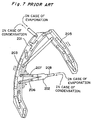
- Fig. 7 shows another example of heat exchangers.
- This heat exchanger is provided with a three-way branched pipe 201 to which a refrigerant flows in at the time of evaporation and a flow merging device 102 from which the refrigerant are discharged at the time of evaporation.
- the refrigerant which flows in from the three-way branched pipe 201 at the time of evaporation is divided into two paths 203, 205 and the refrigerant is evaporated in each path 203, 205.
- the two refrigerant flows 206, 207 are merged at the flow merging device 202 and are allowed to flow out to a refrigerant pipe 208.
- the three-way branched pipe 201 functions as a flow merging device for merging a refrigerant at the time of condensation and that the flow merging device 202 functions as a flow dividing device for dividing the refrigerant at the time of condensation.
- heat exchange efficiency is improved by providing a plurality of refrigerant paths (multiple paths).
- refrigerant drift is caused and the evaporating ability is degraded, particularly, in a gas-liquid two-phase flow.
- This refrigerant drift is caused when the refrigerant is not distributed to each path depending on the thermal load on the air side.
- the distribution ratio of a liquid refrigerant at the time of evaporation or a gas refrigerant at the time of condensation does not match the thermal load on the air side.
- the refrigerant cannot be appropriately distributed if the refrigerant flow rate before the division of a flow is changed. This is because the change in the flow rate affects the distribution state of the refrigerant.
- an orifice should be provided to accelerate the flow so that the change of the distribution state is prevented. In this case, however, there is a problem that pressure loss increases and refrigerant collision noises occur.
- an object of the present invention is to provide a flow merging and dividing device capable of distributing a refrigerant to a plurality of refrigerant flow paths appropriately at all times to maximize its heat exchanging ability and a heat exchanger using the device.
- a heat exchanger having flow merging and dividing means for merging a refrigerant flowing in a plurality of refrigerant flow paths and then dividing the refrigerant to another plurality of refrigerant flow paths.
- This heat exchanger has flow merging and dividing means for merging the refrigerant flows which move in a plurality of refrigerant flow paths and then dividing into another plurality of refrigerant flow paths. Therefore, the refrigerant can be distributed to another plurality of refrigerant flow paths appropriately at all times after refrigerant drift is eliminated by the flow merging and dividing means, and thereby the heat exchanging ability of the heat exchanger can be maximized.
- a flow merging and dividing device comprising: an inlet part having a plurality of inlets; a merging part in which a plurality of refrigerant flows from the plurality of inlets are merged; and an output part having a plurality of outlets to which the refrigerant flows in from the merging part.
- this flow merging and dividing device a plurality of refrigerant flows move in from a plurality of inlets of the inlet part into the merging part so as to merge. Drift of the plurality of refrigerant flows is eliminated by this merge at the merging part. Then, the refrigerant flows which have been merged at the merging part to eliminate the drift are discharged from a plurality of outlets of the outlet part. That is, according to this flow merging and dividing device, after a plurality of refrigerant flows are merged and the drift is eliminated, the refrigerant can be discharged from a plurality of outlets as a plurality of refrigerant flows again. Therefore, the refrigerant can be distributed to a plurality of paths appropriately at all times to maximize the ability of the heat exchanger by using the flow merging and dividing device of the present invention.
- At least an inlet and an outlet are not opposed to each other.
- the flow merging and dividing device further comprises: merging paths for smoothly merging a plurality of refrigerant flows from the plurality of inlets and dividing paths for smoothly dividing the refrigerant from the merging part toward a plurality of outlets.
- the merging paths are used to merge a plurality of refrigerant flows from a plurality of inlets smoothly and guide them to the merging part.
- the dividing paths are used to divide the refrigerant from the merging part smoothly towards a plurality of outlets. Therefore, according to this flow merging and dividing device, the drift of the refrigerant can be prevented without causing any pressure loss. Thus, the ability of the heat exchanger can be further improved.
- a heat exchanger wherein a plurality of refrigerant flow paths are connected to a plurality of inlets of the flow merging and dividing device and another plurality of refrigerant flow paths are connected to a plurality of outlets of the flow merging and dividing device.
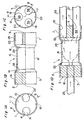
- Fig. 1 shows a first embodiment of the flow merging and dividing device of the present invention.
- this flow merging and dividing device is constituted such that branch pipe connecting members 2, 3 are internally engaged to both axial end parts 1A, 1B of a cylindrical-shape outer pipe 1 made of copper of which approximate central part in the axial direction is slightly constricted.
- the end part 1A of the outer pipe 1 and the branch pipe connecting member 2 constitute an inlet part 5.
- the central part 1C of the outer pipe 1 constitutes a merging part 6.
- the end part 1B of the outer pipe 1 constitutes an outlet part 7.
- Parts 1D, 1E widening from the central part 1C of the outer pipe 1 towards the end parts 1A, 1B constitute a merging path 22 and a dividing path 23.
- the branch pipe connecting member 2 has two axial through trenches 8, 10. These two through trenches 8, 10 are disposed 180° off each other in the circumferential direction.
- the through trenches 8, 10 constitute two inlets.
- the branch pipe connecting member 2 is fixed to the outer pipe 1 by riveting an outer periphery of the end part 1A of the outer pipe 1 at two sites 11, 12 on the outer peripheral surface which are disposed 90° off the two through trenches 8, 10.
- the branch pipe connecting member 3 has three axial through trenches 15, 16, 17. These three axial through trenches 15, 16, 17 are disposed 120° off each other.
- the through trenches 15, 16, 17 constitute three outlets.
- the branch pipe connecting member 3 is fixed to the outer pipe 1 by riveting an outer periphery of the end part 1B of the outer pipe 1 at three sites 20, 21, 22 on the outer peripheral surface which are 60° off the three through trenches 15, 16, 17.
- the through trenches 8, 10 of the inlet part 5 are not opposed to the through trenches 15, 16, 17 of the outlet part 7, but their positions are off each other in the circumferential direction.
- a branch pipe 25 is internally engaged to the through trench 10 of the branch pipe connecting member 2 in the inlet part 5 as a refrigerant pipe.
- Another branch pipe having the same structure as that of this branch pipe 25 is internally engaged to the other through trench 8 though it is not shown in the figure.
- branch pipes 26, 27 are internally engaged to the through trenches 15, 17 of the branch pipe connecting member 3 in the outlet part 7 as refrigerant pipes.
- Another branch pipe having the same structure as that of the branch pipes 26, 27 is internally engaged to the other through trench 16 as a refrigerant pipe though it is not shown in the figure.
- the two inlets 31, 32 are not opposed to the three outlets 33, 35, 36 in this flow merging and dividing device, the refrigerant flows drifted from the inlets 31, 32 are prevented from passing through the merging part 6 and flowing out of the outlets 33, 35, 36 as drift. Therefore, the two refrigerant flows can be reliably merged at the merging part 6 and the drift of the refrigerant flows can be reliably eliminated.
- the merging path 22 can be used to merge two refrigerant flows from the two inlets 31, 32 smoothly and guide them to the merging part 6.
- the dividing path 23 can be used to divide the refrigerant from the merging part 6 toward three outlets 33, 35, 36 smoothly.
- Fig. 2 shows a second embodiment of the flow merging and dividing device of the present invention.
- the second embodiment is different from the first embodiment shown in Fig. 1 only in the next point (i).
- a tapered surface 41A of the protruded part 41 and a tapered surface 1D-1 of a part 1D widening toward the end constitute a merging path 43.
- a tapered surface 42A of the protruded part 42 and a tapered surface 1E-1 of a part 1E widening toward the end constitute a dividing path 45.
- the tapered surface 41A can be utilized to merge inflow refrigerant flows more smoothly than the merging path 22 of the first embodiment.
- the tapered surface 42A can be utilized to divide the merged refrigerant more smoothly than the dividing path 23 of the first embodiment. Therefore, according to the second embodiment, pressure loss can be further decreased and a more efficient heat exchanger can be constituted compared with the first embodiment.
- the branch pipes 25, 26, 27 are inserted and soldered to the branch pipe connecting members 2, 3 in the above first and second embodiments. It is noted, however, that three holes 302A and two holes 303A may be formed in end walls 302, 303, respectively, of both axial ends of a cylindrical member 301 as shown in Fig. 5C. Three branch pipes 305 communicating with the three holes 302A of the end wall 302 may be welded to the end wall 302 and two branch pipes 306 communicating with the two holes 303A of the end wall 303 nay be welded to the end wall 303.
- flow dividing devices 311, 312 may be connected to both ends of a connecting pipe 310 to constitute a flow merging and dividing device 313 as shown in Fig. 5A.
- the flow dividing devices 311, 312 have a large-diameter part 311A, 312A and a small-diameter part 311B, 312B.
- the large-diameter part 311A, 312A and the small-diameter part 311B, 312B are connected with a gentle slope.
- Two branch pipes 315, 316 are connected and communicated with an end surface 313 of the large-diameter part 311A.
- Other two branch pipes 317, 318 are connected and communicated with an end surface 315 of the large-diameter part 312A.
- the two flow dividing devices 311, 312 and the connecting pipe 310 constitute a merging part and the end surfaces 313, 315 of the flow dividing devices 311, 312 constitute an inlet part and an outlet part, respectively.
- the communicating holes 313A, 313B of the end surface 313 constitute inlets and the communicating holes 315A, 315B of the end surface 315 constitute outlets.
- the communicating holes 313A, 313B are not opposed to the communicating holes 315A, 315B.
- branched pipes 321, 322 may be connected to both ends of a connecting pipe 320 to constitute a flow merging and dividing device 323.
- the branched pipes 321, 322 have two branches each, that is, branch parts 324, 325 and branch parts 326, 327.
- Branch pipes 328, 330 are connected to the branch parts 324, 325 and branch pipes 331, 332 are connected to the branch parts 326, 327.
- base parts 321A, 322A of the branched pipes 321, 322 and a connecting pipe 320 constitute a merging part.
- the branch parts 324, 325 of the branched pipe 321 constitute an inlet part and the branch parts 326, 327 of the branched pipe 322 constitute an outlet part.
- Fig. 3 shows a side view of a heat exchanger according to a third embodiment of the present invention.
- This heat exchanger uses a flow merging and dividing device 50 using a branch pipe connecting member 54 in the same constitution as the branch pipe connecting member 2 (see Fig. 3B) instead of the branch pipe connecting member 3 in the flow merging and dividing device of the first embodiment.
- Two through trenches 65, 66 of this branch pipe connecting member 54 are disposed 90° off the two through trenches 8, 10 of the branch pipe connecting member 2 in the circumferential direction.
- a plurality of fin plates 51 bent at an acute angle are disposed at predetermined intervals in the direction perpendicular to the plane of the paper.
- a refrigerant pipe 52 penetrates across the plurality of fin plates 51.
- this heat exchanger has a flow dividing device 53.
- This flow dividing device 53 is connected to one opening 55A of a first refrigerant flow path 55 and one opening 56A of a second refrigerant flow path 56 by a branch pipe 57.
- the first refrigerant flow path 55 is extended penetrating the plurality of fin plates 51 like a needlework along the outer periphery side of a longer bent part 64 of the fin plate 51.
- the other opening 55B of the first refrigerant flow path 55 is connected to one inlet 65 of an inlet part 59 of the flow merging and dividing device 50 by a branch pipe 60.
- the second refrigerant flow path 56 is extended along the outer periphery side of a shorter bent part 67 of the fin plate 51 and then along the inner periphery side after turning at the end part 67A.
- the other opening 56B of this second refrigerant flow path 56 is connected to the other inlet 66 of the inlet part 59 of the flow merging and dividing device 50 by a branch pipe 68.
- This flow merging and dividing device 50 is disposed between the longer bent part 64 and the shorter bent part 67 of the fin plate 51.
- An outlet part 70 of the flow merging and dividing device 50 has two outlets 71, 72 constituted by the through trenches 8, 10.
- the outlet 71 is connected to one opening 75A of a third refrigerant flow path 75 via a branch pipe 73.
- the third refrigerant flow path 75 is extended along the inner periphery side of the bent part 64 and the other opening 75B located slightly lower than the center of the bent part 64 is connected to one opening 77A of a branched pipe 77 by a branch pipe 76.
- the other outlet 72 of the flow merging and dividing device 50 is connected to one opening 80A of a fourth refrigerant flow path 80 via a branch pipe 78.
- the fourth refrigerant flow path 80 is extended upward along the inner periphery side after turning near the lower end of the bent part 56 and the other opening 80B located slightly lower than the center of the bent part 64 is connected to the other opening 77B of a branched pipe 77 by a branch pipe 81.
- one refrigerant flow moves from the flow dividing device 53 to the first refrigerant flow path 55, the branch pipe 60 and the through trench (inlet) 65 of the flow merging and dividing device 50 at the time of evaporation.
- the other refrigerant flow from the flow dividing device 53 moves to the second refrigerant flow path 56, the branch pipe 68 and the through trench (inlet) 66 of the flow merging and dividing device 50.
- These two refrigerant flows are merged at the merging part 6 of the flow merging and dividing device 50 and the drift is eliminated.
- the refrigerant in the merging part 6 flows from the outlets 71, 72 of the outlet part 70 via the branch pipes 73, 78 and passes through the third refrigerant flow path 75 and the fourth refrigerant flow path 80. Then the refrigerant flows into the openings 77A, 77B of the branched pipe 77 via branch pipes 76, 81.
- the refrigerant flow from one opening 77A of the branched pipe 77 flows into the outlet 71 of the outlet part 70 via the branch pipe 76, the third refrigerant flow path 75 and the branch pipe 73.
- the refrigerant flow from the other opening 77B of the branched pipe 77 flows into the outlet 72 of the outlet part 70 via the branch pipe 81, the fourth refrigerant flow path 80 and the branch pipe 78.
- These two refrigerant flows are merged at the merging part 6 of the flow merging and dividing device 50 and the drift is eliminated.
- the refrigerant in the merging part 6 flows from the through trenches 65, 66 of the inlet part 59, passes through the branch pipes 60, 68 and then flows into the first and second refrigerant flow paths 55, 56.
- the drift of the refrigerant from the first and second refrigerant flow paths 55, 56 or the third and fourth refrigerant flow paths 75, 80 can be eliminated by the flow merging and dividing device 50 provided between the first and second refrigerant flow paths 55, 56 and the third and fourth refrigerant flow paths 75, 80. Therefore, the refrigerant can be distributed appropriately at all times to the third and fourth refrigerant flow paths 75, 80 or the first and second refrigerant flow paths 55, 56. Thus, the heat exchanging ability can be maximized.
- Fig. 4 shows a side view of a heat exchanger according to a fourth embodiment of the present invention.
- This heat exchanger uses the flow merging and dividing device 50 provided in the third embodiment. Also, this heat exchanger is provided with fin plates 51 provided in the third embodiment.
- a refrigerant pipe 90 penetrates the fin plates 51 in the direction perpendicular to the plane of the paper.
- one opening pipe 91 is connected to one opening 90A of the refrigerant pipe 90 before branching.
- the other opening 90B of this refrigerant pipe 90 is connected to a first opening 92A of a three-way branched pipe 92.
- a second opening 92B of the three-way branched pipe 92 is connected to one opening 93A of a first refrigerant flow path 93 and a third opening 92C is connected to one opening 95A of a second refrigerant flow path 95.
- the first refrigerant flow path 93 is extended penetrating the plurality of fin plates 51 like a needlework along a longer bent part 64 of the fin plate 51.
- the other opening 93B of the first refrigerant flow path 93 is connected to one through trench 65 of an inlet part 59 of the flow merging and dividing device 50 by a branch pipe 60.
- the second refrigerant flow path 95 is extended from the upper end part of the longer bent part 64 of the fin plate 51 over the upper end of a shorter bent part 67 of the fin plate 51 and further along the outer periphery side of this bent part 67.
- the other opening 95B of this second refrigerant flow path 95 located in the vicinity of the lower end of the shorter bent part 67 is connected to the other through trench 66 of the inlet part 59 of the flow merging and dividing device 50 by a branch pipe 96.
- An outlet part 70 of the flow merging and dividing device 50 has two outlets constituted by the through trenches 8, 10.
- the outlet constituted by the through trench 8 is connected to one opening 80A of a third refrigerant flow path 80 via a branch pipe 78.
- the third refrigerant flow path 80 is extended along the inner periphery side of the bent part 64 and the other opening 80B located slightly lower than the center of the bent part 64 is connected to one opening 77B of a branched pipe 77 by a branch pipe 81.
- the other outlet 71 of the flow merging and dividing device 50 is connected to one opening 98A of a fourth refrigerant flow path 98 via a branch pipe 97.
- the fourth refrigerant flow path 98 is connected to a refrigerant pipe 90 in the vicinity of the center of the bent part 64 by a gangway pipe 99 from the vicinity of the upper end of the bent part 67 and the other opening 98B is connected to the other opening 77A of a branched pipe 77 by a branch pipe 100.
- refrigerant flows divided to the first refrigerant flow path 93 and the second refrigerant flow path 95 can be merged in the flow merging and dividing device 50 at the time of evaporation. Then, the refrigerant flow of which drift has been eliminated by this merge can be divided to the third refrigerant flow path 80 and the fourth refrigerant flow path 98.
- the refrigerant flows divided to the third refrigerant flow path 80 and the fourth refrigerant flow path 98 can be merged in the flow merging and dividing device 50. Then, the refrigerant flow of which drift has been eliminated by this merge can be divided to the first refrigerant flow path 93 and the second refrigerant flow path 95.
- the drift of the refrigerant from the first and second refrigerant flow paths 93, 95 or the third and fourth refrigerant flow paths 80, 98 can be eliminated by the flow merging and dividing device 50. Therefore, the refrigerant can be distributed appropriately at all times to the third and fourth refrigerant flow paths 80, 98 or the first arid second refrigerant flow paths 93, 95. Thus, the heat exchanging ability can be maximized.
- the present invention can be applied in a heat exchanger of outdoor equipment although the heat exchangers of indoor equipment are described in the third and fourth embodiments.
- the present invention can be applied to a heat exchanger having a plurality of refrigerant flow paths and is useful in distributing a refrigerant to the plurality of refrigerant flow paths appropriately at all times to maximize the heat exchanging ability.
Applications Claiming Priority (3)
| Application Number | Priority Date | Filing Date | Title |
|---|---|---|---|
| JP14894998 | 1998-05-29 | ||
| JP14894998 | 1998-05-29 | ||
| PCT/JP1999/002568 WO1999063285A1 (fr) | 1998-05-29 | 1999-05-18 | Dispositif de fusion et division de flux et echangeur thermique faisant appel a ce dispositif |
Publications (3)
| Publication Number | Publication Date |
|---|---|
| EP1085280A1 true EP1085280A1 (fr) | 2001-03-21 |
| EP1085280A4 EP1085280A4 (fr) | 2002-11-06 |
| EP1085280B1 EP1085280B1 (fr) | 2006-06-14 |
Family
ID=15464268
Family Applications (1)
| Application Number | Title | Priority Date | Filing Date |
|---|---|---|---|
| EP99919631A Expired - Lifetime EP1085280B1 (fr) | 1998-05-29 | 1999-05-18 | Dispositif de fusion et division de flux et echangeur thermique faisant appel a ce dispositif |
Country Status (10)
| Country | Link |
|---|---|
| US (1) | US6363967B1 (fr) |
| EP (1) | EP1085280B1 (fr) |
| KR (1) | KR100378258B1 (fr) |
| CN (1) | CN100338417C (fr) |
| AT (1) | ATE330190T1 (fr) |
| DE (1) | DE69931914T2 (fr) |
| ES (1) | ES2267265T3 (fr) |
| ID (1) | ID27160A (fr) |
| PT (1) | PT1085280E (fr) |
| WO (1) | WO1999063285A1 (fr) |
Cited By (10)
| Publication number | Priority date | Publication date | Assignee | Title |
|---|---|---|---|---|
| WO2007017969A1 (fr) | 2005-08-08 | 2007-02-15 | Mitsubishi Denki Kabushiki Kaisha | Climatiseur et procédé de fabrication d’un climatiseur |
| US20130100759A1 (en) * | 2011-10-24 | 2013-04-25 | United States Gypsum Company | Multiple-leg discharge boot for slurry distribution |
| US9296124B2 (en) | 2010-12-30 | 2016-03-29 | United States Gypsum Company | Slurry distributor with a wiping mechanism, system, and method for using same |
| US9579822B2 (en) | 2010-12-30 | 2017-02-28 | United States Gypsum Company | Slurry distribution system and method |
| US9616591B2 (en) | 2010-12-30 | 2017-04-11 | United States Gypsum Company | Slurry distributor, system and method for using same |
| US9999989B2 (en) | 2010-12-30 | 2018-06-19 | United States Gypsum Company | Slurry distributor with a profiling mechanism, system, and method for using same |
| US10052793B2 (en) | 2011-10-24 | 2018-08-21 | United States Gypsum Company | Slurry distributor, system, and method for using same |
| US10059033B2 (en) | 2014-02-18 | 2018-08-28 | United States Gypsum Company | Cementitious slurry mixing and dispensing system with pulser assembly and method for using same |
| US10076853B2 (en) | 2010-12-30 | 2018-09-18 | United States Gypsum Company | Slurry distributor, system, and method for using same |
| US10293522B2 (en) | 2011-10-24 | 2019-05-21 | United States Gypsum Company | Multi-piece mold and method of making slurry distributor |
Families Citing this family (13)
| Publication number | Priority date | Publication date | Assignee | Title |
|---|---|---|---|---|
| US7753074B2 (en) * | 2006-07-28 | 2010-07-13 | Masco Corporation Of Indiana | Mixing valve |
| US20130264294A1 (en) * | 2011-09-29 | 2013-10-10 | James Andrew McDermott | Building Air Conditioner Evaporator Condensation Management System |
| CN103185339B (zh) * | 2011-12-28 | 2016-08-03 | 株式会社能率 | 浓淡火焰燃烧器及燃烧装置 |
| JP6076636B2 (ja) * | 2012-07-17 | 2017-02-08 | カルソニックカンセイ株式会社 | 蒸発器構造 |
| JP6086057B2 (ja) * | 2013-11-29 | 2017-03-01 | 株式会社富士通ゼネラル | 熱交換器 |
| WO2016002088A1 (fr) * | 2014-07-04 | 2016-01-07 | 三菱電機株式会社 | Distributeur de fluide réfrigérant et dispositif de pompe à chaleur comprenant un distributeur de fluide réfrigérant |
| JP2016044830A (ja) * | 2014-08-20 | 2016-04-04 | 株式会社富士通ゼネラル | 熱交換器、およびこれを用いた空気調和機 |
| US9878144B2 (en) * | 2014-10-14 | 2018-01-30 | Wilmarc Holdings, Llc | Connector system |
| WO2017082321A1 (fr) * | 2015-11-12 | 2017-05-18 | 東芝キヤリア株式会社 | Dispositif à cycle frigorifique et unité extérieure de dispositif de climatisation |
| CN106595020B (zh) * | 2016-11-29 | 2022-11-01 | 广州华凌制冷设备有限公司 | 换热翅片、多折式换热器和空调器 |
| CN107587869B (zh) * | 2017-07-28 | 2021-03-19 | 中国石油天然气股份有限公司 | 一种用于产液剖面测井的井下实时气体分流器和系统 |
| US10743462B2 (en) * | 2019-01-11 | 2020-08-18 | Cnh Industrial America Llc | Flow splitter for distributing agricultural products and related system |
| JP7137092B2 (ja) * | 2021-01-22 | 2022-09-14 | ダイキン工業株式会社 | 熱交換器 |
Citations (3)
| Publication number | Priority date | Publication date | Assignee | Title |
|---|---|---|---|---|
| US3110162A (en) * | 1962-02-12 | 1963-11-12 | Carrier Corp | Refrigerant flow distribution means |
| US3563055A (en) * | 1969-03-17 | 1971-02-16 | Sporlan Valve Co | Refrrigerant distribvtor |
| US4982572A (en) * | 1989-05-02 | 1991-01-08 | 810296 Ontario Inc. | Vapor injection system for refrigeration units |
Family Cites Families (12)
| Publication number | Priority date | Publication date | Assignee | Title |
|---|---|---|---|---|
| US4126058A (en) * | 1977-07-18 | 1978-11-21 | Caterpillar Tractor Co. | Fluid flow divider |
| JPS54132842A (en) * | 1978-04-06 | 1979-10-16 | Sanyo Electric Co Ltd | Freezer |
| US4489721A (en) * | 1982-12-30 | 1984-12-25 | The Regents Of The University Of California | Double lumen tube adaptor and valve system for medical anesthesia circuits |
| FI84844C (fi) * | 1985-01-24 | 1996-03-29 | Ahlstroem Oy | Foerfarande och anordning foer att foerdela och foerena stroemmar av hoegkonsistenta fibersuspensioner |
| JPH037863A (ja) * | 1989-06-02 | 1991-01-16 | Matsushita Refrig Co Ltd | 蒸発器 |
| US5203384A (en) * | 1990-08-15 | 1993-04-20 | Dresser Industries, Inc. | Combination casting for a blending dispenser |
| US5250041A (en) * | 1992-01-16 | 1993-10-05 | Fresenius Usa, Inc. | Tubing administration set for use in peritoneal dialysis |
| JPH0722372U (ja) * | 1993-09-30 | 1995-04-21 | 東洋ラジエーター株式会社 | フィンチューブ型熱交換器の冷媒混合器 |
| EP0723125B1 (fr) * | 1994-12-09 | 2001-10-24 | Kabushiki Kaisha Kobe Seiko Sho | Procédé et installation de liquéfaction de gaz |
| JP3577813B2 (ja) * | 1995-11-27 | 2004-10-20 | オイレス工業株式会社 | 自動車排気管用の継手装置 |
| JPH10160288A (ja) | 1996-11-25 | 1998-06-19 | Hitachi Ltd | 冷媒分流装置 |
| JP3410309B2 (ja) | 1996-12-04 | 2003-05-26 | 松下エコシステムズ株式会社 | 空気調和機の分流管 |
-
1999
- 1999-05-18 PT PT99919631T patent/PT1085280E/pt unknown
- 1999-05-18 US US09/700,042 patent/US6363967B1/en not_active Expired - Fee Related
- 1999-05-18 EP EP99919631A patent/EP1085280B1/fr not_active Expired - Lifetime
- 1999-05-18 KR KR10-2000-7012566A patent/KR100378258B1/ko not_active IP Right Cessation
- 1999-05-18 AT AT99919631T patent/ATE330190T1/de not_active IP Right Cessation
- 1999-05-18 ES ES99919631T patent/ES2267265T3/es not_active Expired - Lifetime
- 1999-05-18 ID IDW20002416A patent/ID27160A/id unknown
- 1999-05-18 WO PCT/JP1999/002568 patent/WO1999063285A1/fr active IP Right Grant
- 1999-05-18 DE DE69931914T patent/DE69931914T2/de not_active Expired - Lifetime
- 1999-05-18 CN CNB998067857A patent/CN100338417C/zh not_active Expired - Fee Related
Patent Citations (3)
| Publication number | Priority date | Publication date | Assignee | Title |
|---|---|---|---|---|
| US3110162A (en) * | 1962-02-12 | 1963-11-12 | Carrier Corp | Refrigerant flow distribution means |
| US3563055A (en) * | 1969-03-17 | 1971-02-16 | Sporlan Valve Co | Refrrigerant distribvtor |
| US4982572A (en) * | 1989-05-02 | 1991-01-08 | 810296 Ontario Inc. | Vapor injection system for refrigeration units |
Non-Patent Citations (1)
| Title |
|---|
| See also references of WO9963285A1 * |
Cited By (17)
| Publication number | Priority date | Publication date | Assignee | Title |
|---|---|---|---|---|
| EP1798490A1 (fr) * | 2005-08-08 | 2007-06-20 | Mitsubishi Electric Corporation | Climatiseur et procédé de fabrication d un climatiseur |
| EP1798490A4 (fr) * | 2005-08-08 | 2008-09-10 | Mitsubishi Electric Corp | Climatiseur et procédé de fabrication d un climatiseur |
| US7703504B2 (en) | 2005-08-08 | 2010-04-27 | Mitsubishi Electric Corporation | Air conditioner and manufacturing method therefor |
| WO2007017969A1 (fr) | 2005-08-08 | 2007-02-15 | Mitsubishi Denki Kabushiki Kaisha | Climatiseur et procédé de fabrication d’un climatiseur |
| US10076853B2 (en) | 2010-12-30 | 2018-09-18 | United States Gypsum Company | Slurry distributor, system, and method for using same |
| US9296124B2 (en) | 2010-12-30 | 2016-03-29 | United States Gypsum Company | Slurry distributor with a wiping mechanism, system, and method for using same |
| US9579822B2 (en) | 2010-12-30 | 2017-02-28 | United States Gypsum Company | Slurry distribution system and method |
| US9616591B2 (en) | 2010-12-30 | 2017-04-11 | United States Gypsum Company | Slurry distributor, system and method for using same |
| US10245611B2 (en) | 2010-12-30 | 2019-04-02 | United States Gypsum Company | Slurry distribution system and method |
| US9999989B2 (en) | 2010-12-30 | 2018-06-19 | United States Gypsum Company | Slurry distributor with a profiling mechanism, system, and method for using same |
| US10239230B2 (en) | 2010-12-30 | 2019-03-26 | United States Gypsum Company | Slurry distributor, system and method for using same |
| US20130100759A1 (en) * | 2011-10-24 | 2013-04-25 | United States Gypsum Company | Multiple-leg discharge boot for slurry distribution |
| US10052793B2 (en) | 2011-10-24 | 2018-08-21 | United States Gypsum Company | Slurry distributor, system, and method for using same |
| US9909718B2 (en) * | 2011-10-24 | 2018-03-06 | United States Gypsum Company | Multiple-leg discharge boot for slurry distribution |
| US10286572B2 (en) | 2011-10-24 | 2019-05-14 | United States Gypsum Company | Flow splitter for slurry distribution system |
| US10293522B2 (en) | 2011-10-24 | 2019-05-21 | United States Gypsum Company | Multi-piece mold and method of making slurry distributor |
| US10059033B2 (en) | 2014-02-18 | 2018-08-28 | United States Gypsum Company | Cementitious slurry mixing and dispensing system with pulser assembly and method for using same |
Also Published As
| Publication number | Publication date |
|---|---|
| EP1085280A4 (fr) | 2002-11-06 |
| WO1999063285A1 (fr) | 1999-12-09 |
| DE69931914D1 (de) | 2006-07-27 |
| KR20010025006A (ko) | 2001-03-26 |
| ATE330190T1 (de) | 2006-07-15 |
| US6363967B1 (en) | 2002-04-02 |
| ID27160A (id) | 2001-03-08 |
| DE69931914T2 (de) | 2007-01-18 |
| KR100378258B1 (ko) | 2003-03-29 |
| PT1085280E (pt) | 2006-09-29 |
| CN100338417C (zh) | 2007-09-19 |
| CN1303471A (zh) | 2001-07-11 |
| ES2267265T3 (es) | 2007-03-01 |
| EP1085280B1 (fr) | 2006-06-14 |
Similar Documents
| Publication | Publication Date | Title |
|---|---|---|
| EP1085280B1 (fr) | Dispositif de fusion et division de flux et echangeur thermique faisant appel a ce dispositif | |
| KR101770493B1 (ko) | 적층형 헤더, 열교환기 및 공기 조화 장치 | |
| US5157944A (en) | Evaporator | |
| US20180224220A1 (en) | Stacking-type header, heat exchanger, and air-conditioning apparatus | |
| CN105229404B (zh) | 层叠型联管箱、热交换器和空气调节装置 | |
| JP3358250B2 (ja) | 冷媒蒸発器 | |
| EP2998679A1 (fr) | Collecteur stratifié, échangeur thermique, et climatiseur | |
| JPWO2019058540A1 (ja) | 冷媒分配器、及び、空気調和装置 | |
| EP2998680B1 (fr) | Colonne stratifiée, échangeur de chaleur, et climatiseur | |
| JP6138264B2 (ja) | 積層型ヘッダー、熱交換器、及び、空気調和装置 | |
| WO2015045073A1 (fr) | Collecteur de type stratifié, échangeur thermique, et appareil de climatisation | |
| CN114279242B (zh) | 板组、板和换热器装置 | |
| WO2017042866A1 (fr) | Distributeur, collecteur stratifié, échangeur de chaleur et climatiseur | |
| CN111936815B (zh) | 分配器以及热交换器 | |
| CN110440079B (zh) | 连接管组件、换热器、制冷系统和空调器 | |
| JPH11325656A (ja) | ヘッダー分流器 | |
| JP2000111205A (ja) | 分配器及び空気調和機 | |
| JPH07133971A (ja) | 熱交換器の冷媒分流器 | |
| JP2003035471A (ja) | 分流器およびそれを用いた空気調和機 | |
| JP3326930B2 (ja) | 冷媒分流器 | |
| EP4220064A1 (fr) | Échangeur de chaleur et appareil de climatisation comprenant un échangeur de chaleur | |
| JP2018013259A (ja) | 冷媒分流器およびそれを用いた冷凍システム | |
| JP2021139532A (ja) | 熱交換器 |
Legal Events
| Date | Code | Title | Description |
|---|---|---|---|
| PUAI | Public reference made under article 153(3) epc to a published international application that has entered the european phase |
Free format text: ORIGINAL CODE: 0009012 |
|
| 17P | Request for examination filed |
Effective date: 20001127 |
|
| AK | Designated contracting states |
Kind code of ref document: A1 Designated state(s): AT BE CH CY DE DK ES FI FR GB GR IE IT LI LU MC NL PT SE |
|
| A4 | Supplementary search report drawn up and despatched | ||
| AK | Designated contracting states |
Kind code of ref document: A4 Designated state(s): AT BE CH CY DE DK ES FI FR GB GR IE IT LI LU MC NL PT SE |
|
| A4 | Supplementary search report drawn up and despatched |
Effective date: 20021106 |
|
| 17Q | First examination report despatched |
Effective date: 20040518 |
|
| GRAP | Despatch of communication of intention to grant a patent |
Free format text: ORIGINAL CODE: EPIDOSNIGR1 |
|
| GRAS | Grant fee paid |
Free format text: ORIGINAL CODE: EPIDOSNIGR3 |
|
| GRAA | (expected) grant |
Free format text: ORIGINAL CODE: 0009210 |
|
| AK | Designated contracting states |
Kind code of ref document: B1 Designated state(s): AT BE CH CY DE DK ES FI FR GB GR IE IT LI LU MC NL PT SE |
|
| PG25 | Lapsed in a contracting state [announced via postgrant information from national office to epo] |
Ref country code: NL Free format text: LAPSE BECAUSE OF FAILURE TO SUBMIT A TRANSLATION OF THE DESCRIPTION OR TO PAY THE FEE WITHIN THE PRESCRIBED TIME-LIMIT Effective date: 20060614 Ref country code: LI Free format text: LAPSE BECAUSE OF FAILURE TO SUBMIT A TRANSLATION OF THE DESCRIPTION OR TO PAY THE FEE WITHIN THE PRESCRIBED TIME-LIMIT Effective date: 20060614 Ref country code: IT Free format text: LAPSE BECAUSE OF FAILURE TO SUBMIT A TRANSLATION OF THE DESCRIPTION OR TO PAY THE FEE WITHIN THE PRESCRIBED TIME-LIMIT;WARNING: LAPSES OF ITALIAN PATENTS WITH EFFECTIVE DATE BEFORE 2007 MAY HAVE OCCURRED AT ANY TIME BEFORE 2007. THE CORRECT EFFECTIVE DATE MAY BE DIFFERENT FROM THE ONE RECORDED. Effective date: 20060614 Ref country code: FI Free format text: LAPSE BECAUSE OF FAILURE TO SUBMIT A TRANSLATION OF THE DESCRIPTION OR TO PAY THE FEE WITHIN THE PRESCRIBED TIME-LIMIT Effective date: 20060614 Ref country code: CH Free format text: LAPSE BECAUSE OF FAILURE TO SUBMIT A TRANSLATION OF THE DESCRIPTION OR TO PAY THE FEE WITHIN THE PRESCRIBED TIME-LIMIT Effective date: 20060614 Ref country code: AT Free format text: LAPSE BECAUSE OF FAILURE TO SUBMIT A TRANSLATION OF THE DESCRIPTION OR TO PAY THE FEE WITHIN THE PRESCRIBED TIME-LIMIT Effective date: 20060614 |
|
| REG | Reference to a national code |
Ref country code: GB Ref legal event code: FG4D |
|
| REG | Reference to a national code |
Ref country code: CH Ref legal event code: EP |
|
| REG | Reference to a national code |
Ref country code: IE Ref legal event code: FG4D |
|
| REF | Corresponds to: |
Ref document number: 69931914 Country of ref document: DE Date of ref document: 20060727 Kind code of ref document: P |
|
| PG25 | Lapsed in a contracting state [announced via postgrant information from national office to epo] |
Ref country code: SE Free format text: LAPSE BECAUSE OF FAILURE TO SUBMIT A TRANSLATION OF THE DESCRIPTION OR TO PAY THE FEE WITHIN THE PRESCRIBED TIME-LIMIT Effective date: 20060914 Ref country code: DK Free format text: LAPSE BECAUSE OF FAILURE TO SUBMIT A TRANSLATION OF THE DESCRIPTION OR TO PAY THE FEE WITHIN THE PRESCRIBED TIME-LIMIT Effective date: 20060914 |
|
| REG | Reference to a national code |
Ref country code: PT Ref legal event code: SC4A Effective date: 20060810 |
|
| REG | Reference to a national code |
Ref country code: GR Ref legal event code: EP Ref document number: 20060403143 Country of ref document: GR |
|
| NLV1 | Nl: lapsed or annulled due to failure to fulfill the requirements of art. 29p and 29m of the patents act | ||
| REG | Reference to a national code |
Ref country code: CH Ref legal event code: PL |
|
| ET | Fr: translation filed | ||
| REG | Reference to a national code |
Ref country code: ES Ref legal event code: FG2A Ref document number: 2267265 Country of ref document: ES Kind code of ref document: T3 |
|
| PLBE | No opposition filed within time limit |
Free format text: ORIGINAL CODE: 0009261 |
|
| STAA | Information on the status of an ep patent application or granted ep patent |
Free format text: STATUS: NO OPPOSITION FILED WITHIN TIME LIMIT |
|
| 26N | No opposition filed |
Effective date: 20070315 |
|
| GBPC | Gb: european patent ceased through non-payment of renewal fee |
Effective date: 20070518 |
|
| PG25 | Lapsed in a contracting state [announced via postgrant information from national office to epo] |
Ref country code: MC Free format text: LAPSE BECAUSE OF NON-PAYMENT OF DUE FEES Effective date: 20070531 |
|
| PG25 | Lapsed in a contracting state [announced via postgrant information from national office to epo] |
Ref country code: IE Free format text: LAPSE BECAUSE OF NON-PAYMENT OF DUE FEES Effective date: 20070518 Ref country code: GB Free format text: LAPSE BECAUSE OF NON-PAYMENT OF DUE FEES Effective date: 20070518 |
|
| PG25 | Lapsed in a contracting state [announced via postgrant information from national office to epo] |
Ref country code: LU Free format text: LAPSE BECAUSE OF NON-PAYMENT OF DUE FEES Effective date: 20070518 Ref country code: CY Free format text: LAPSE BECAUSE OF FAILURE TO SUBMIT A TRANSLATION OF THE DESCRIPTION OR TO PAY THE FEE WITHIN THE PRESCRIBED TIME-LIMIT Effective date: 20060614 |
|
| PGFP | Annual fee paid to national office [announced via postgrant information from national office to epo] |
Ref country code: PT Payment date: 20100428 Year of fee payment: 12 |
|
| PGFP | Annual fee paid to national office [announced via postgrant information from national office to epo] |
Ref country code: BE Payment date: 20100423 Year of fee payment: 12 |
|
| PGFP | Annual fee paid to national office [announced via postgrant information from national office to epo] |
Ref country code: GR Payment date: 20100421 Year of fee payment: 12 |
|
| REG | Reference to a national code |
Ref country code: PT Ref legal event code: MM4A Free format text: LAPSE DUE TO NON-PAYMENT OF FEES Effective date: 20111118 |
|
| BERE | Be: lapsed |
Owner name: *DAIKIN INDUSTRIES LTD Effective date: 20110531 |
|
| PG25 | Lapsed in a contracting state [announced via postgrant information from national office to epo] |
Ref country code: PT Free format text: LAPSE BECAUSE OF NON-PAYMENT OF DUE FEES Effective date: 20111118 |
|
| REG | Reference to a national code |
Ref country code: GR Ref legal event code: ML Ref document number: 20060403143 Country of ref document: GR Effective date: 20111202 |
|
| PG25 | Lapsed in a contracting state [announced via postgrant information from national office to epo] |
Ref country code: GR Free format text: LAPSE BECAUSE OF NON-PAYMENT OF DUE FEES Effective date: 20111202 |
|
| PG25 | Lapsed in a contracting state [announced via postgrant information from national office to epo] |
Ref country code: BE Free format text: LAPSE BECAUSE OF NON-PAYMENT OF DUE FEES Effective date: 20110531 |
|
| REG | Reference to a national code |
Ref country code: FR Ref legal event code: PLFP Year of fee payment: 18 |
|
| REG | Reference to a national code |
Ref country code: FR Ref legal event code: PLFP Year of fee payment: 19 |
|
| PGFP | Annual fee paid to national office [announced via postgrant information from national office to epo] |
Ref country code: DE Payment date: 20170509 Year of fee payment: 19 Ref country code: FR Payment date: 20170413 Year of fee payment: 19 |
|
| PGFP | Annual fee paid to national office [announced via postgrant information from national office to epo] |
Ref country code: IT Payment date: 20170522 Year of fee payment: 19 Ref country code: ES Payment date: 20170605 Year of fee payment: 19 |
|
| REG | Reference to a national code |
Ref country code: DE Ref legal event code: R119 Ref document number: 69931914 Country of ref document: DE |
|
| PG25 | Lapsed in a contracting state [announced via postgrant information from national office to epo] |
Ref country code: IT Free format text: LAPSE BECAUSE OF NON-PAYMENT OF DUE FEES Effective date: 20180518 Ref country code: DE Free format text: LAPSE BECAUSE OF NON-PAYMENT OF DUE FEES Effective date: 20181201 Ref country code: FR Free format text: LAPSE BECAUSE OF NON-PAYMENT OF DUE FEES Effective date: 20180531 |
|
| REG | Reference to a national code |
Ref country code: ES Ref legal event code: FD2A Effective date: 20190913 |
|
| PG25 | Lapsed in a contracting state [announced via postgrant information from national office to epo] |
Ref country code: ES Free format text: LAPSE BECAUSE OF NON-PAYMENT OF DUE FEES Effective date: 20180519 |