EP1071118B1 - Substrate rotating apparatus - Google Patents
Substrate rotating apparatus Download PDFInfo
- Publication number
- EP1071118B1 EP1071118B1 EP00115587A EP00115587A EP1071118B1 EP 1071118 B1 EP1071118 B1 EP 1071118B1 EP 00115587 A EP00115587 A EP 00115587A EP 00115587 A EP00115587 A EP 00115587A EP 1071118 B1 EP1071118 B1 EP 1071118B1
- Authority
- EP
- European Patent Office
- Prior art keywords
- rotor
- rotating apparatus
- magnetic
- partition
- stator
- Prior art date
- Legal status (The legal status is an assumption and is not a legal conclusion. Google has not performed a legal analysis and makes no representation as to the accuracy of the status listed.)
- Expired - Lifetime
Links
- 239000000758 substrate Substances 0.000 title claims description 69
- 230000005291 magnetic effect Effects 0.000 claims description 150
- 238000005192 partition Methods 0.000 claims description 59
- 238000012545 processing Methods 0.000 claims description 39
- 239000000470 constituent Substances 0.000 claims description 30
- 238000006073 displacement reaction Methods 0.000 claims description 29
- 238000010926 purge Methods 0.000 claims description 15
- 238000001816 cooling Methods 0.000 claims description 14
- 239000000463 material Substances 0.000 claims description 14
- 239000000725 suspension Substances 0.000 claims description 9
- 230000002093 peripheral effect Effects 0.000 claims description 7
- 238000005339 levitation Methods 0.000 claims description 5
- 238000003860 storage Methods 0.000 claims description 2
- 238000010586 diagram Methods 0.000 description 12
- 230000001965 increasing effect Effects 0.000 description 10
- 239000000696 magnetic material Substances 0.000 description 9
- 230000005856 abnormality Effects 0.000 description 7
- 239000004065 semiconductor Substances 0.000 description 6
- 239000010409 thin film Substances 0.000 description 6
- 230000008859 change Effects 0.000 description 5
- 238000001514 detection method Methods 0.000 description 5
- 230000009467 reduction Effects 0.000 description 4
- VYPSYNLAJGMNEJ-UHFFFAOYSA-N silicon dioxide Inorganic materials O=[Si]=O VYPSYNLAJGMNEJ-UHFFFAOYSA-N 0.000 description 4
- 239000010935 stainless steel Substances 0.000 description 4
- 238000004804 winding Methods 0.000 description 4
- 238000006243 chemical reaction Methods 0.000 description 3
- 230000004907 flux Effects 0.000 description 3
- 238000004519 manufacturing process Methods 0.000 description 3
- 230000001681 protective effect Effects 0.000 description 3
- 229910001220 stainless steel Inorganic materials 0.000 description 3
- 229910052782 aluminium Inorganic materials 0.000 description 2
- XAGFODPZIPBFFR-UHFFFAOYSA-N aluminium Chemical compound [Al] XAGFODPZIPBFFR-UHFFFAOYSA-N 0.000 description 2
- 239000004020 conductor Substances 0.000 description 2
- 238000011161 development Methods 0.000 description 2
- 230000018109 developmental process Effects 0.000 description 2
- 230000001939 inductive effect Effects 0.000 description 2
- 230000007246 mechanism Effects 0.000 description 2
- 238000000034 method Methods 0.000 description 2
- 239000010453 quartz Substances 0.000 description 2
- 238000004151 rapid thermal annealing Methods 0.000 description 2
- 230000004044 response Effects 0.000 description 2
- 238000007789 sealing Methods 0.000 description 2
- 230000035945 sensitivity Effects 0.000 description 2
- 238000012546 transfer Methods 0.000 description 2
- 235000012431 wafers Nutrition 0.000 description 2
- RYGMFSIKBFXOCR-UHFFFAOYSA-N Copper Chemical compound [Cu] RYGMFSIKBFXOCR-UHFFFAOYSA-N 0.000 description 1
- ZOKXTWBITQBERF-UHFFFAOYSA-N Molybdenum Chemical compound [Mo] ZOKXTWBITQBERF-UHFFFAOYSA-N 0.000 description 1
- -1 SUS316 Substances 0.000 description 1
- 230000002159 abnormal effect Effects 0.000 description 1
- 230000004323 axial length Effects 0.000 description 1
- 239000003575 carbonaceous material Substances 0.000 description 1
- 239000000919 ceramic Substances 0.000 description 1
- 229910052681 coesite Inorganic materials 0.000 description 1
- 230000000295 complement effect Effects 0.000 description 1
- 229910052802 copper Inorganic materials 0.000 description 1
- 239000010949 copper Substances 0.000 description 1
- 229910052906 cristobalite Inorganic materials 0.000 description 1
- 230000002950 deficient Effects 0.000 description 1
- 230000001419 dependent effect Effects 0.000 description 1
- 238000013461 design Methods 0.000 description 1
- 239000000428 dust Substances 0.000 description 1
- 230000000694 effects Effects 0.000 description 1
- 230000005294 ferromagnetic effect Effects 0.000 description 1
- 230000005484 gravity Effects 0.000 description 1
- 238000010438 heat treatment Methods 0.000 description 1
- 230000006872 improvement Effects 0.000 description 1
- 230000006698 induction Effects 0.000 description 1
- 239000007769 metal material Substances 0.000 description 1
- 229910052750 molybdenum Inorganic materials 0.000 description 1
- 239000011733 molybdenum Substances 0.000 description 1
- 238000012544 monitoring process Methods 0.000 description 1
- 230000010355 oscillation Effects 0.000 description 1
- 239000002245 particle Substances 0.000 description 1
- 229910000889 permalloy Inorganic materials 0.000 description 1
- 230000008569 process Effects 0.000 description 1
- 230000008439 repair process Effects 0.000 description 1
- 230000001846 repelling effect Effects 0.000 description 1
- 239000000377 silicon dioxide Substances 0.000 description 1
- 229910001256 stainless steel alloy Inorganic materials 0.000 description 1
- 229910052682 stishovite Inorganic materials 0.000 description 1
- 230000001360 synchronised effect Effects 0.000 description 1
- 229910052905 tridymite Inorganic materials 0.000 description 1
- XLYOFNOQVPJJNP-UHFFFAOYSA-N water Substances O XLYOFNOQVPJJNP-UHFFFAOYSA-N 0.000 description 1
- 238000003466 welding Methods 0.000 description 1
Images


Classifications
-
- H—ELECTRICITY
- H01—ELECTRIC ELEMENTS
- H01L—SEMICONDUCTOR DEVICES NOT COVERED BY CLASS H10
- H01L21/00—Processes or apparatus adapted for the manufacture or treatment of semiconductor or solid state devices or of parts thereof
- H01L21/67—Apparatus specially adapted for handling semiconductor or electric solid state devices during manufacture or treatment thereof; Apparatus specially adapted for handling wafers during manufacture or treatment of semiconductor or electric solid state devices or components ; Apparatus not specifically provided for elsewhere
- H01L21/683—Apparatus specially adapted for handling semiconductor or electric solid state devices during manufacture or treatment thereof; Apparatus specially adapted for handling wafers during manufacture or treatment of semiconductor or electric solid state devices or components ; Apparatus not specifically provided for elsewhere for supporting or gripping
- H01L21/687—Apparatus specially adapted for handling semiconductor or electric solid state devices during manufacture or treatment thereof; Apparatus specially adapted for handling wafers during manufacture or treatment of semiconductor or electric solid state devices or components ; Apparatus not specifically provided for elsewhere for supporting or gripping using mechanical means, e.g. chucks, clamps or pinches
- H01L21/68714—Apparatus specially adapted for handling semiconductor or electric solid state devices during manufacture or treatment thereof; Apparatus specially adapted for handling wafers during manufacture or treatment of semiconductor or electric solid state devices or components ; Apparatus not specifically provided for elsewhere for supporting or gripping using mechanical means, e.g. chucks, clamps or pinches the wafers being placed on a susceptor, stage or support
- H01L21/68792—Apparatus specially adapted for handling semiconductor or electric solid state devices during manufacture or treatment thereof; Apparatus specially adapted for handling wafers during manufacture or treatment of semiconductor or electric solid state devices or components ; Apparatus not specifically provided for elsewhere for supporting or gripping using mechanical means, e.g. chucks, clamps or pinches the wafers being placed on a susceptor, stage or support characterised by the construction of the shaft
-
- F—MECHANICAL ENGINEERING; LIGHTING; HEATING; WEAPONS; BLASTING
- F16—ENGINEERING ELEMENTS AND UNITS; GENERAL MEASURES FOR PRODUCING AND MAINTAINING EFFECTIVE FUNCTIONING OF MACHINES OR INSTALLATIONS; THERMAL INSULATION IN GENERAL
- F16C—SHAFTS; FLEXIBLE SHAFTS; ELEMENTS OR CRANKSHAFT MECHANISMS; ROTARY BODIES OTHER THAN GEARING ELEMENTS; BEARINGS
- F16C32/00—Bearings not otherwise provided for
- F16C32/04—Bearings not otherwise provided for using magnetic or electric supporting means
- F16C32/0406—Magnetic bearings
- F16C32/044—Active magnetic bearings
- F16C32/047—Details of housings; Mounting of active magnetic bearings
-
- F—MECHANICAL ENGINEERING; LIGHTING; HEATING; WEAPONS; BLASTING
- F16—ENGINEERING ELEMENTS AND UNITS; GENERAL MEASURES FOR PRODUCING AND MAINTAINING EFFECTIVE FUNCTIONING OF MACHINES OR INSTALLATIONS; THERMAL INSULATION IN GENERAL
- F16C—SHAFTS; FLEXIBLE SHAFTS; ELEMENTS OR CRANKSHAFT MECHANISMS; ROTARY BODIES OTHER THAN GEARING ELEMENTS; BEARINGS
- F16C2300/00—Application independent of particular apparatuses
- F16C2300/40—Application independent of particular apparatuses related to environment, i.e. operating conditions
- F16C2300/42—Application independent of particular apparatuses related to environment, i.e. operating conditions corrosive, i.e. with aggressive media or harsh conditions
-
- F—MECHANICAL ENGINEERING; LIGHTING; HEATING; WEAPONS; BLASTING
- F16—ENGINEERING ELEMENTS AND UNITS; GENERAL MEASURES FOR PRODUCING AND MAINTAINING EFFECTIVE FUNCTIONING OF MACHINES OR INSTALLATIONS; THERMAL INSULATION IN GENERAL
- F16C—SHAFTS; FLEXIBLE SHAFTS; ELEMENTS OR CRANKSHAFT MECHANISMS; ROTARY BODIES OTHER THAN GEARING ELEMENTS; BEARINGS
- F16C2300/00—Application independent of particular apparatuses
- F16C2300/40—Application independent of particular apparatuses related to environment, i.e. operating conditions
- F16C2300/62—Application independent of particular apparatuses related to environment, i.e. operating conditions low pressure, e.g. elements operating under vacuum conditions
Definitions
- the present invention relates to a substrate rotating apparatus for rotating a substrate to be processed, e.g. a semiconductor substrate, in a processing chamber. More particularly, the present invention relates to a substrate rotating apparatus for rotating a substrate in a processing chamber of a system in which a substrate is processed in a special atmosphere, e.g. in a CVD system for forming a thin film on a substrate, an etcher system for thinly removing the surface of a substrate, or a rapid thermal annealing (RTA) system.
- a substrate rotating apparatus for rotating a substrate in a processing chamber of a system in which a substrate is processed in a special atmosphere e.g. in a CVD system for forming a thin film on a substrate, an etcher system for thinly removing the surface of a substrate, or a rapid thermal annealing (RTA) system.
- a CVD system for forming a thin film on a substrate
- etcher system for thinly removing the surface of a substrate
- a substrate 101 to be processed is mounted on a substrate holder or susceptor 102 and rotated in a processing chamber 103 by rotating the substrate holder or susceptor 102.
- This kind of system involves some problems, e.g. generation of dust or release of gas from a rotating mechanism for rotating the substrate holder or susceptor 102, and a problem in terms of the lifetime of bearings.
- magnetic bearings radial bearings 105 and 106 and an axial bearing 107
- a corrosive gas is often used in the processing chamber 103. Therefore, the gas contact portion of a stator-side constituent member of each magnetic bearing is covered with a cylindrical pressure resistive partition (can).
- a cylindrical pressure resistive partition can
- the diameter of the substrate 101 increases, the diameter of the rotor 104 of the rotating mechanism also increases. Consequently, it is necessary to increase the strength (rigidity) of the pressure resistive partition.
- the wall thickness to withstand a buckling stress of 1 kgf ⁇ cm 2 is about 3 to 5 mm.
- the wall thickness is about 0.3 mm, i.e. about one tenth of the above-mentioned value, buckling stress is reached when the pressure difference is 1 Torr. Accordingly, as the diameter of the rotor 104 increases, the wall thickness of the partition also needs to be increased.
- Increasing the wall thickness of the partition causes an increase in the gaps between stator-side electromagnets 105a, 106a, 107a and 107b and rotor-side targets of the radial magnetic bearings 105 and 106 and the axial magnetic bearing 107, resulting in a reduction in control magnetic force.
- reference numeral 108 denotes a motor stator for applying rotational force to the rotor 104; 109 denotes a quartz window; 110 denotes a lamp heater unit for heating the inside of the processing chamber 3; and 111 and 112 denote load-unload gates for loading and unloading the substrate 101 into and out of the chamber 3.
- the diameter of the rotor 104 increases, the diameters of the electromagnets 107a and 107b of the axial magnetic bearing 107 also increase. Accordingly, unstable torque (unbalanced torque) produced by the electromagnets 107a and 107b becomes so large that it cannot be ignored. If two radial magnetic bearings 105 and 106 are provided axially spaced (for 4 axes, two for each bearing) for the purpose of compensating for the unbalanced torque, the axial length increases, and hence the space efficiency lowers. Regarding the rotor characteristics, the design is dangerous because the inertia moment ratio of the rotor is close to 1.
- WO 97/15978 A relates to an integrated magnetic levitation and rotation system and was used as a basis for the preamble of claim 1.
- a rotary motor and a rotary magnetic bearing are integrated in a compact assembly that is contactless.
- a stator assembly surrounds a ferromagnetic rotor with an annular air gap which can accommodate a cylindrical wall, e.g. of a chamber, for semiconductor wafer processing.
- the stator assembly has a permanent magnet or magnets sandwiched between vertically spaced magnetic stator plates with plural pole segments.
- the rotor is preferably a ring of magnetic stainless steel with complementary pole teeth.
- the stator assembly levitates and passively centers the rotor along a vertical axis and against tilt about the either horizontal axis, provides a radial position bias for the rotor, and establishes a motor flux field at the rotor poles.
- Polyphase coils wound on the stator plates produce a rotating flux field that drives the rotor as a synchronous homopolar motor.
- a rotor without pole teeth allows operation with an asynchronous inductive drive.
- a controller energizes control coils wound on each stator pole segment in response to a sensed physical position of the rotor. The control coils provide active radial position control and can actively damp tip and tilt oscillations that may overcome the passive centering.
- US-A-5,630,881 discloses a thin-film forming device including a reaction chamber having an atmosphere different from that in the outside world, a susceptor rotatably disposed in the reaction chamber for mounting a substrate thereon to form a thin film thereon, and a nozzle disposed within the reaction chamber facing the susceptor for supplying a thin-film forming material on the substrate, the thin-film forming device comprises: a levitating means including magnetic bearings for non-contact support of the susceptor; and a driving means for rotating the susceptor at high speed, to thereby increase the rotational speed of the susceptor and the thin-film forming rate.
- an object of the present invention is to provide a substrate rotating apparatus which is capable of avoiding increase in size of the diameter of the electromagnet of the axial magnetic bearing and capable of reducing unstable force such as unstable torque produced by the electromagnets, even if the diameter of the rotor is increased.
- Another object of the present invention is to provide a substrate rotating apparatus which is capable of avoiding an increase in magnetic reluctance between the rotor-side target and the stator-side magnet yoke even if the partition provided therebetween is formed from thick-walled material and whereby large control magnetic force can be obtained without enlarging the size of the magnetic bearings or without increasing the number of windings thereof.
- the present invention provides a substrate rotating apparatus as set forth in claim 1. Preferred embodiments of the present invention may be gathered from the dependent claims.
- the axial magnetic bearing is divided into three magnetic bearings and these magnetic bearings are positioned so that imaginary lines connecting points where the divided axial magnetic bearings are disposed form an approximately regular triangle, even if the diameter of the rotor increases, the diameter of the electromagnet of each of the axial magnetic bearings will not increase.
- position control in the axial direction is effected at the position of each axial magnetic bearing, motion about the radial axes is also stabilized. Accordingly, any unstable force such as unstable torque (unbalanced torque) produced by the electromagnets of the conventional axial magnetic bearing is minimized.
- the rotor is placed in a space communicating with the processing chamber, and stator-side constituent members of the magnetic bearings and a stator-side constituent member of the motor are placed in a space defined outside the space communicating with the processing chamber by a partition provided between the rotor and the stator-side constituent members.
- a material electromagnetically equivalent to yokes of electromagnets as stator-side constituent members of the magnetic bearings is fitted in or inserted in portions of the partition where the yokes are located, and the partition constitutes a stator housing as a whole.
- the ends of yokes of electromagnets as stator-side constituent members of the magnetic bearings may pierce through the partition so as to face the rotor directly.
- translational motion in two radial axes is preferably passively supported by a radial restoring force generated when the relative position between the yoke of an electromagnet as a stator-side constituent member of the axial magnetic bearing and the horizontal disk as a rotor-side constituent member of the axial magnetic bearing is displaced in a translational direction (horizontal direction).
- radial magnetic bearings may be provided at one or a plural of axial position(s).
- the stator housing has a cooling zone in the vicinity of the processing chamber and further has a gas purge zone located across the cooling zone from the processing chamber.
- Fig. 2 is a diagram schematically showing the arrangement of the substrate rotating apparatus according to the present invention.
- a substrate 1 to be processed is mounted on a ring-like substrate holder or susceptor 2 and rotated about its axis X in a processing chamber 3 by rotating the substrate holder or susceptor 2.
- the substrate holder or susceptor 2 is secured to the upper end of a cylindrical rotor 4.
- the rotor 4 is supported in a magnetic levitation manner by a radial magnetic bearing 5 and an axial magnetic bearing 6 as detailed later.
- reference numeral 8 denotes a motor stator for applying rotational force to the rotor 4; 9 denotes a quartz window; 10 denotes a lamp heater unit; 11 and 12 denote load-unload gates for loading and unloading the substrate 1; 13 denotes a horizontal disk as a rotor-side target of the axial magnetic bearing 6, which is horizontally provided on the outer periphery of the rotor 4; 15 denotes cooling zones; and 16 denotes a gas purge zone. The details of each part will be described below.
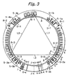
- Figs. 3 to 6 are diagrams showing the arrangement of the substrate rotating apparatus according to the present invention.
- Fig. 3 is a diagram showing the planar arrangement of component parts.
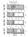
- Figs. 4(a) to 4(e) show sections taken along the lines A-A to E-E In Fig. 3 , respectively.
- Figs. 5(f) to 5(j) show sections taken along the lines F-F to J-J in Fig. 3 , respectively.
- Fig. 6 is a development of the outer peripheral surface of the apparatus.
- electromagnets 5-1a, 5-2a, 5-3a and 5-4a which are stator-side constituent members of radial magnetic bearings 5-1 to 5-4, are disposed to face the outer peripheral surface of a cylindrical rotor 4.
- the electromagnets 5-1a and 5-3a pair up with each other to support the rotor 4 in X-axis direction.
- the electromagnets 5-2a and 5-4a pair up with each other to support the rotor 4 in Y-axis direction.
- Displacement sensors 5-1b, 5-1c, 5-2b, 5-2c, 5-3b, 5-3c, 5-4b and 5-4c which are stator-side constituent members of the radial magnetic bearings 5-1 to 5-4, are disposed to face the outer periphery of the rotor 4 in the vicinity of the electromagnets 5-1a, 5-2a, 5-3a and 5-4a, respectively to detect displacement of the rotor 4 in X and Y axes directions ( Figs. 3 and 6 ).
- each pair of the displacement sensors one is used for monitoring the displacement of the rotor and the other one is used for controlling of the same.
- the axial magnetic bearing 6 is divided into three axial magnetic bearings 6-1, 6-2 and 6-3, which are positioned so that lines L1, L2 and L3 connecting points where the axial magnetic bearings 6-1, 6-2 and 6-3 are disposed form an approximately regular triangle.
- the axial magnetic bearing 6-1 has two upper electromagnets 6-1a and 6-1b and one lower electromagnet 6-1c as stator-side constituent members, which are disposed to face upper and lower surfaces of the horizontal disk 13.
- the axial magnetic bearing 6-2 has two upper electromagnets 6-2a and 6-2b and one lower electromagnet 6-2c, which are disposed to face upper and lower surfaces of the horizontal disk 13.
- the axial magnetic bearing 6-3 also has two upper electromagnets 6-3a and 6-3b and one lower electromagnet 6-3c, which are disposed to face upper and lower surfaces of the horizontal disk 13.
- each axial magnetic bearing the two upper electromagnets are provided to prepare for or cope with the change in the specification of the mass of the rotor or load thereto.
- Displacement sensors 6-1d, 6-2d and 6-3d which are stator-side constituent members of the axial magnetic bearing 6, are disposed to face lower surface of the horizontal disk 13 in the vicinity of the lower electromagnets 6-1c, 6-2c and 6-3c, respectively.
- stators 8-1 and 8-2 of a motor 8 are disposed to face the rotor 4.
- the rotor 4 is placed in a space communicating with the processing chamber 3.
- the stator-side constituent members of the radial magnetic bearing 5, the axial magnetic bearing 6 and the motor 8 are placed in a space defined outside the space communicating with the processing chamber 3 by a partition (can) 14 provided between the rotor 4 and the stator-side constituent members.
- the thickness of the partition 14 be reduced to be as thin as possible from the viewpoint of reducing the size of each of the electromagnets 5-1a to 5-4a of the radial magnetic bearings 5-1 to 5-4 and the electromagnets 6-1a, 6-1b and 6-1c to 6-3a, 6-3b and 6-3c of the axial magnetic bearings 6-1 to 6-3.
- the partition 14 in the present invention has a pressure vessel structure.
- Portions 14a of the partition 14 where the yokes (magnetic poles) of the electromagnets 5-1a to 5-4a and the electromagnets 6-1a, 6-1b and 6-1c to 6-3a, 6-3b and 6-3c are located are made of a magnetic material of the same electromagnetic property as that of the yokes.
- the magnetic material is fitted in or inserted in the portions 14a of the partition 14.
- the partition 14 is subjected to finishing to form a pressure vessel structure.
- the gap between the yokes and the rotor 4 is reduced, and it is possible to apply increased control magnetic force to the rotor 4. Accordingly, it is unnecessary to increase the size or the magnetomotive force (ampere-turns) of the electromagnets despite the provision of the partition 14 having a pressure vessel structure.
- the partition 14 has cooling zones (water cooling jackets) 15 provided in the vicinity of a portion thereof that is coupled to the processing chamber 3 to remove both heat from the processing chamber 3 and heat from the upper electromagnets 6-1a and 6-1b to 6-3a and 6-3b of the axial magnetic bearings 6-1 to 6-3.
- cooling zones water cooling jackets
- the partition 14 further has a gas purge zone 16 located across the cooling zones 15 from the processing chamber 3 to supply a gas in the gap between the rotor 4 and a portion of the partition 14 where the cooling zones 15 are located.
- a gas of good thermal conductivity is used in the gas purge zone 16 to transfer heat from the rotor 4 to the cooling zones 15 efficiently.
- the displacement sensors 5-1b and 5-1c to 5-4b and 5-4c of the radial magnetic bearings 5-1 to 5-4 and the displacement sensors 6-1d to 6-3d of the axial magnetic bearings 6-1 to 6-3 are positioned more away from the processing chamber 3 than the cooling zones 15, the gas purge zone 16 and the upper electromagnets 6-1a and 6-1b to 6-3a and 6-3b of the axial magnetic bearings 6-1 to 6-3, which bear the weight of the rotor 4, thereby maintaining the stability of the sensor function.
- the displacement sensors 5-1b and 5-1c to 5-4b and 5-4c and the displacement sensors 6-1d to 6-3d are inductance type sensors.
- a thin non-magnetic partition (can) (not shown) is put between these sensors and the rotor-side sensor target.
- the thin partition has a cap-shaped structure, which is sealed with respect to the main partition 14 with an O-ring 17.
- the inductance type sensor detects a change in the gap between the sensor and a levitating target (in this case, the rotor 4) on the basis of a change in the inductance of a detection coil.
- a natural frequency signal carrier signal
- the coil inductance changes, and hence the electric current flowing through the coil changes.
- the carrier signal modulated by the change in the inductance of the detection coil is effectively detected by using a bridge circuit. If an electrically conductive material is used for the partition 14, a secondary circuit occurs and undesirably affects the detection coil as a mutual conductance. Therefore, the frequency of the sensor carrier signal is lowered to reduce the influence of the secondary circuit, although this trades off the response frequency performance of the sensor.
- the gap between the rotor side and the stator side can be set to be relatively large at a portion provided radial magnetic bearings 5-1 to 5-4 (for 2 axes), which is positioned approximately at the height of the gravity center of the rotor 4, and the motor 8, which is positioned below it. Therefore, portion 4a of the rotor 4 in this part is made of a non-magnetic material.
- One type of induction motor is used as the motor 8.
- the main reason for using a non-magnetic material for the rotor-side target (the portion 4a of the rotor 4) of the motor 8 is to minimize radial external force at the position of the motor 8 and to reduce the load on the radial magnetic bearings 5-1 to 5-4, thereby correspondingly reducing the size of the radial magnetic bearings 5-1 to 5-4.
- the portion 4a of the rotor 4, which serves as the rotor of the motor 8, is made of a surface-treated aluminum material.
- the portion 4b of the rotor 4 above the portion 4a, at which the displacement sensors 5-1b and 5-1c to 5-4b and 5-4c and the electromagnets 5-1a to 5-4a of the radial magnetic bearings 5-1 to 5-4 are located, is made of a magnetic material (e.g. electromagnetic stainless steel or permalloy).
- a portion 4c of the rotor 4 above the portion 4b is made of an austenic stainless steel, e.g. SUS316, molybdenum, or a surface-treated carbon material because this portion 4c is closer to the processing chamber 3 including a corrosive gas of high temperature.
- the processing temperature of the substrate 1 in the processing chamber 3 reaches 1000°C, it is necessary to provide a sufficient temperature gradient in the course of heat transfer from the processing chamber 3 through the rotor 4 to the axial magnetic bearings 6-1 to 6-3 and the radial magnetic bearings 5-1 to 5-4. Therefore, the portion 4c of the rotor 4, at which the cooling zones 15 and the gas purge zone 16 are located, has a reduced wall thickness.
- the axial magnetic bearing 6 is divided into three, which is equal to the smallest number of axes necessary for stable horizontal support of the rotor, as stated above. Therefore, the operation of the axial magnetic bearing can be controlled by using a conventional control circuit adapted to control each axis independently. Accordingly, it is possible to reduce the size and costs of the controller.
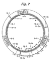
- Fig. 7 is a diagram showing the planar arrangement of the gas purge zone 16.
- the gas purge zone 16 is divided into zones 16-1, 16-2 and 16-3.
- the zones 16-1, 16-2 and 16-3 have purge gas supply chambers 16-1a, 16-2a and 16-3a, respectively, each having openings that open on the inner side thereof.
- the openings of the zones 16-1, 16-2 and 16-3 are provided by nozzle plates 16-1b, 16-2b and 16-3b, respectively, each having a large number of nozzle holes.
- the purge gas When a purge gas is supplied into the purge gas chambers 16-1a, 16-2a and 16-3a from gas inlets 16-1c, 16-2c and 16-3c, the purge gas is supplied to the gap between the rotor 4 and the partition 14 through the nozzle plates 16-1b, 16-2b and 16-3b.
- the substrate rotating apparatus is provided with touch-down bearings that operate when the radial magnetic bearings 5-1 to 5-4 and the axial magnetic bearings 6-1 to 6-3 do not operate properly.
- the touch-down bearings include a radial touch-down bearing 18 for supporting the rotor 4 in the radial direction and an axial touch-down bearing 19 for supporting the rotor 4 in the axial direction.
- the radial touch-down bearing 18 has a plurality of bearings 18-1 with a small diameter that are rotatably supported by respective support members 18-2.
- the bearings 18-1 are disposed at predetermined intervals around the outer periphery of the rotor 4 below the horizontal disk 13 with a predetermined gap between each bearing 18-1 and the outer peripheral surface of the rotor 4.
- the axial touch-down bearing 19 has a plurality of bearings 19-1 with a small diameter that are rotatably supported by respective support members 19-2.
- the bearings 19-1 are disposed at predetermined intervals at each of the upper and lower surfaces of the horizontal disk 13 with a predetermined gap between each bearing 19-1 and the upper and lower surface of the horizontal disk 13.
- the upper electromagnets 6-1a and 6-1b to 6-3a and 6-3b of the axial magnetic bearings 6-1 to 6-3, which are located above the horizontal disk 13, are adapted to generate restoring force in the radial direction.
- Fig. 8 Illustrates the generation of restoring force.
- Fig. 8(a) is a diagram showing the positional relationship between the upper electromagnet 6-1a and the horizontal disk 13, and
- Fig. 8(b) is an enlarged view of portion A in Fig. 8(b) .
- the arrangement of the radial magnetic bearing may be as follows. As shown in Fig .9(a) , electromagnets 21 having exciting windings on U-shaped yokes (magnetic poles) are disposed (in the X- and Y-axis directions) on the stator side to face the rotor 4 made of a magnetic material, and magnetic attraction force is used as radial control force.
- the radial magnetic bearing may be arranged such that electromagnets 5-1a to 5-4a having the same electromagnet structure as the above, i.e. having exciting windings on U-shaped yokes, are similarly disposed on the stator side as shown in Fig. 9(a) , but the rotor 4 is formed by using a non-magnetic material of low resistivity (e.g. aluminum or copper), and an inductive repelling force is used as a radial control force.
- a non-magnetic material of low resistivity e.g. aluminum or copper
- a cylindrical rotor 4 with a large diameter When a cylindrical rotor 4 with a large diameter is subjected to control forces in the X- and Y-axis directions, it is deformed by the control forces if the rigidity thereof is not sufficient. Deformation of the rotor 4 can be prevented by disposing the electromagnets 5-1a to 5-4a as shown in Fig. 9(b) . That is, the electromagnets 5-1a and 5-3a are disposed to face each other across the rotor 4 in the Y-axis direction, and the electromagnets 5-2a and 5-4a are disposed to face each other across the rotor 4 in the X-axis direction.
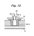
- reference numeral 20 in Figs. 5 and 6 denotes a rotational position sensor for detecting the rotational position of the rotor 4.
- An eddy-current type sensor is used as the rotational position sensor 20.
- the eddy-current type sensor requires that the partition 14 be a non-electrical conductor. Therefore, as shown in Fig. 10 , a protective casing 20-1 made of SiO 2 ceramic is disposed through the partition 14 so as to face the rotor 4, and an eddy-current type sensor element 20-2 is accommodated in the protective casing 20-1.
- reference numeral 20-3 denotes an O-ring for sealing between the protective casing 20-1 and the partition 14.
- the electromagnets and the displacement sensors of the magnetic bearings are protected from exposure to a special atmosphere, e.g. a corrosive gas, by placing a partition (can) between the electromagnets and the displacement sensors and the rotor.
- a partition can
- the gap between the rotor and the electromagnets and displacement sensors increases by an amount corresponding to the thickness of the partition.
- This causes the magnetic reluctance to increase. Consequently, the control magnetic force of the electromagnets reduces, and the sensitivity of the displacement sensors degrades.
- the partition needs to be formed into a thick-walled pressure resistive partition. Accordingly, it is necessary to increase the magnetomotive force of the coils of the electromagnets and those of the displacement sensors, and hence the coils become large in size.
- the portions 14a of the partition 14, where the yokes of the electromagnets 5-1a to 5-4a of the radial magnetic bearings 5-1 to 5-4 and the electromagnets 6-1a, 6-1b and 6-1c to 6-3a, 6-3b and 6-3c of the axial magnetic bearings 6-1 to 6-3 are located are made of a magnetic material of the same electromagnetic property as that of the yokes.
- the magnetic material is fitted in or inserted in the portions 14a of the partition 14 to solve the above-described problem, as stated above.
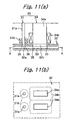
- the solution measures will be described below more specifically with reference to Fig. 11.
- Fig. 11 shows the arrangement of a magnetic bearing, in which Fig. 11(a) is a sectional view of the magnetic bearing, and Fig. 11(b) is a view as seen in the direction of the arrow A-A in Fig. 11(a) .
- a partition 32 is made of a non-magnetic metal material.
- Magnetic members 32a are fitted in or inserted in portions of the partition 32 where the ends of a sensor yoke 31a of a displacement sensor 31 of a magnetic bearing 30 are located so that the magnetic members 32a face a levitating member or rotor 33.
- the magnetic members 32a are made of the same material or material having a same electromagnetic property as that of the sensor yoke 31a.
- magnetic members 32b are fitted in portions of the partition 32 where the ends of a magnet yoke 34a of an electromagnet 34 are located so that the magnetic members 32b face the levitating member 33.
- the magnetic members 32b are made of the same material or material having a same electromagnetic property as that of the magnet yoke 34a.
- the portions of the partition 32 in which the magnetic members 32a and 32b are fitted are provided with joint sealing portions 35 and 36, respectively, by welding or the like. It should be noted that a sensor coil 31b is fitted on the sensor yoke 31a, and a magnet coil 34b is fitted on the magnet yoke 34a.
- the magnetic members 32a and 32b are fitted in the portions of the partition 32 where the sensor yoke 31a and the magnet yoke 34a are located, respectively, even if the wall thickness of the partition 32 is increased, there will be no increase in the magnetic reluctance between the sensor yoke 31a and the levitating member 33 and in the magnetic reluctance between the magnet yoke 34a and the levitating member 33.
- the sensor sensitivity is improved, and hence it is possible to detect a displacement of the levitating member 33 with high accuracy. Therefore, it is unnecessary to increase the size of the sensor coil 31b.
- the magnetic members 32a and 32b are fitted in or inserted in the portions of the partition 32 where the ends of the sensor yoke 31a and the magnet yoke 34a are located, respectively, the arrangement may be such that the ends of the sensor yoke 31a and the magnet yoke 34a themselves pierce through the partition 32 to face the levitating member 33 directly.
- Measures 1) may further include suspending the rotation of the rotor.
- measures 1) only after a displacement sensor output has exceeded a certain set value, an abnormality is recognized, and the rotor suddenly touches down undesirably.
- measures 2) also, only after a displacement sensor output has exceeded a certain set value, an abnormality is recognized, and the rotation of the rotor is suspended suddenly.
- an abnormality detecting circuit is constructed by using three comparator circuits 41, 42 and 43 as shown for example in Fig. 12 . That is, threshold values (reference values) S1, S2 and S3 are set in the comparator circuits 41, 42 and 43, respectively. The threshold values S1, S2 and S3 are related to each other as shown in Fig. 13 , i.e.
- a displacement sensor output signal So is input to each of the comparator circuits 41, 42 and 43.
- the comparator circuit 41 drives an alarm circuit 44 to output an alarm only.
- the comparator circuit 42 drives both a failure output circuit 45 and a motor operation suspension circuit 46 to notify the occurrence of a failure and to suspend the motor operation.
- the comparator circuit 43 drives the failure output circuit 45, the motor operation suspension circuit 46 and a magnetic bearing suspension circuit 47 to notify the occurrence of a failure and to suspend the motor operation and the levitation control of the magnetic bearings.
- an abnormality is detected stepwisely, and an abnormal situation is inputted stepwisely to the main control unit of the semiconductor manufacturing system, which controls the substrate rotating apparatus, thereby making it possible to reduce the incidence of suspension of the rotor during processing of a substrate.
- the abnormality detecting circuit shown in Fig. 12 is merely an example, and the present invention is not necessarily limited thereto.
- the arrangement may be such that the threshold values S1, S2 and S3 of the displacement sensors are stored in a storage unit in advance, and the processing in each of the comparator circuits 41, 42 and 43 is executed by a computer to deliver an alarm output or a failure output and to suspend the motor operation and the magnetic bearing control.
- the number of threshold values is not necessarily limited to 3 but may be 2 or more.
- the present invention provides the following advantageous effects.
- the axial magnetic bearing is divided into three or more magnetic bearings and these magnetic bearings are positioned so that imaginary lines connecting points where the divided axial magnetic bearings are disposed form an approximately regular triangle or polygon.
- the operation of the axial magnetic bearing can be controlled by using a conventional control circuit adapted to control each axis independently. Accordingly, it is possible to simplify the controller and to achieve a reduction in size of the controller.
- the diameter of the rotor increases, the diameter of the electromagnet of each of the axial magnetic bearings will not increase.
- position control in the axial direction is effected at the position of each axial magnetic bearing, motion about the radial axes is also stabilized. Accordingly, any unstable force such as unstable torque (unbalanced torque) produced by the electromagnets of the conventional axial magnetic bearing is minimized.
- the rotor may be placed in a space communicating with the processing chamber, and the stator-side constituent members of the magnetic bearings and the stator-side constituent member of the motor may be placed in a space defined outside the space communicating with the processing chamber by a partition provided between the rotor and the stator-side constituent members.
- a material electromagnetically equivalent to the yokes of electromagnets as stator-side constituent members of the magnetic bearings may be fitted in portions of the partition where the yokes are located, and the partition may constitute a stator housing as a whole. Instead, the ends of yokes of electromagnets as stator-side constituent members of the magnetic bearings may pierce through the partition so as to face the rotor directly.
- the wall thickness of the partition is increased to form a pressure resistive partition, there is no reduction in magnetic control force. Accordingly, it is possible to provide a substrate rotating apparatus capable of meeting the demands for an increased lifetime, non-particle environment and improvement in the occupied space efficiency in the field of semiconductor manufacture, in which substrates to be processed are becoming larger in diameter. Furthermore, because the stator-side constituent members of the magnetic bearings may be disposed outside the partition, it is possible to replace or repair the component parts of the magnetic bearings and the motor components while keeping the processing chamber and the space communicating with the processing chamber under a special atmosphere.
- Translational motion in two radial axes may be passively supported by radial restoring force generated when the relative position between the yoke of an electromagnet as a stator-side constituent member of the axial magnetic bearing and the horizontal disk as a rotor-side constituent member of the axial magnetic bearing is displaced in a translational direction (horizontal direction). Accordingly, the rotor can be stably supported in a magnetic levitation manner.
- stator housing may include a cooling zone in the vicinity of the processing chamber and further may Include a gas purge zone located across the cooling zone from the processing chamber. Therefore, it is possible to suppress a rise in temperature of displacement sensors of the magnetic bearings and hence possible to detect the displacement of the rotor position with high accuracy.
- the radial magnetic bearing is provided at one axial position of the substitute rotating apparatus, it is preferable to provide at two or more axial positions to further stabilize the rotor.
Landscapes
- Engineering & Computer Science (AREA)
- General Engineering & Computer Science (AREA)
- Mechanical Engineering (AREA)
- Physics & Mathematics (AREA)
- Condensed Matter Physics & Semiconductors (AREA)
- General Physics & Mathematics (AREA)
- Manufacturing & Machinery (AREA)
- Computer Hardware Design (AREA)
- Microelectronics & Electronic Packaging (AREA)
- Power Engineering (AREA)
- Magnetic Bearings And Hydrostatic Bearings (AREA)
- Container, Conveyance, Adherence, Positioning, Of Wafer (AREA)
Applications Claiming Priority (4)
| Application Number | Priority Date | Filing Date | Title |
|---|---|---|---|
| JP20537499 | 1999-07-19 | ||
| JP20537499 | 1999-07-19 | ||
| JP36955899 | 1999-12-27 | ||
| JP36955899A JP3923696B2 (ja) | 1999-07-19 | 1999-12-27 | 基板回転装置 |
Publications (3)
| Publication Number | Publication Date |
|---|---|
| EP1071118A2 EP1071118A2 (en) | 2001-01-24 |
| EP1071118A3 EP1071118A3 (en) | 2005-10-26 |
| EP1071118B1 true EP1071118B1 (en) | 2008-09-24 |
Family
ID=26515036
Family Applications (1)
| Application Number | Title | Priority Date | Filing Date |
|---|---|---|---|
| EP00115587A Expired - Lifetime EP1071118B1 (en) | 1999-07-19 | 2000-07-19 | Substrate rotating apparatus |
Country Status (6)
| Country | Link |
|---|---|
| US (1) | US6373159B1 (ko) |
| EP (1) | EP1071118B1 (ko) |
| JP (1) | JP3923696B2 (ko) |
| KR (1) | KR100726016B1 (ko) |
| DE (1) | DE60040320D1 (ko) |
| TW (1) | TW517277B (ko) |
Cited By (1)
| Publication number | Priority date | Publication date | Assignee | Title |
|---|---|---|---|---|
| WO2014054034A3 (en) * | 2012-10-05 | 2014-11-27 | Koninklijke Philips N.V. | Rotary positioning device |
Families Citing this family (25)
| Publication number | Priority date | Publication date | Assignee | Title |
|---|---|---|---|---|
| JP2001182746A (ja) * | 1999-12-27 | 2001-07-06 | Ebara Corp | 磁気軸受装置 |
| DE20006302U1 (de) * | 2000-04-06 | 2001-10-25 | Band Zink Gmbh | Beschichtungsvorrichtung |
| JP2002093724A (ja) * | 2000-09-18 | 2002-03-29 | Tokyo Electron Ltd | 熱処理装置 |
| JP2002212729A (ja) * | 2001-01-17 | 2002-07-31 | Hitachi Kokusai Electric Inc | 基板処理装置および半導体装置の製造方法 |
| US6770146B2 (en) * | 2001-02-02 | 2004-08-03 | Mattson Technology, Inc. | Method and system for rotating a semiconductor wafer in processing chambers |
| JP2004528721A (ja) * | 2001-05-29 | 2004-09-16 | アイクストロン、アーゲー | 支持体およびその上にガス支持され回転駆動される基板保持器から構成される装置 |
| US6876122B2 (en) * | 2002-09-16 | 2005-04-05 | Lockheed Martin Corporation | Circular rail linear induction motor |
| KR100439276B1 (ko) * | 2003-11-24 | 2004-07-30 | 코닉 시스템 주식회사 | 급속열처리 장치 |
| JP2006179613A (ja) * | 2004-12-21 | 2006-07-06 | Rigaku Corp | 半導体ウエハ縦型熱処理装置用磁性流体シールユニット |
| DE102005032184A1 (de) * | 2005-07-09 | 2007-01-18 | Saurer Gmbh & Co. Kg | Verfahren zum Betreiben eines elektromotorischen Antriebs |
| JP4885000B2 (ja) * | 2007-02-13 | 2012-02-29 | 株式会社ニューフレアテクノロジー | 気相成長装置および気相成長方法 |
| KR101532060B1 (ko) | 2007-06-27 | 2015-06-26 | 브룩스 오토메이션 인코퍼레이티드 | 셀프 베어링 모터를 위한 위치 피드백 |
| WO2009012396A2 (en) * | 2007-07-17 | 2009-01-22 | Brooks Automation, Inc. | Substrate processing apparatus with motors integral to chamber walls |
| KR101958874B1 (ko) | 2008-06-04 | 2019-03-15 | 가부시키가이샤 에바라 세이사꾸쇼 | 기판처리장치, 기판처리방법, 기판 파지기구, 및 기판 파지방법 |
| JP5533335B2 (ja) * | 2009-07-22 | 2014-06-25 | 東京エレクトロン株式会社 | 処理装置及びその動作方法 |
| KR101288483B1 (ko) * | 2010-04-21 | 2013-07-26 | 주성엔지니어링(주) | 기판 처리장치 |
| KR101312962B1 (ko) * | 2011-09-07 | 2013-10-01 | 스미도모쥬기가이고교 가부시키가이샤 | 반송장치 |
| US9394938B2 (en) | 2013-06-19 | 2016-07-19 | Applied Materials, Inc. | Internal chamber rotation motor, alternative rotation |
| DE102013011873B4 (de) | 2013-07-17 | 2015-10-08 | Mecatronix Ag | Positioniervorrichtung und Verfahren zum Bewegen eines Substrats |
| JP6387863B2 (ja) * | 2015-03-05 | 2018-09-12 | 株式会社島津製作所 | 磁気軸受装置 |
| CN109099065B (zh) * | 2018-09-30 | 2020-02-18 | 珠海格力电器股份有限公司 | 焊接防护套和磁悬浮轴向轴承 |
| CN114072586B (zh) * | 2019-07-19 | 2023-11-03 | 株式会社易威奇 | 泵 |
| KR20230091507A (ko) * | 2021-12-16 | 2023-06-23 | 에이피시스템 주식회사 | 자기부상 회전 장치 및 자기부상 회전 방법 |
| JP2024002304A (ja) * | 2022-06-23 | 2024-01-11 | 東京エレクトロン株式会社 | 成膜装置 |
| CN117005025B (zh) * | 2023-09-01 | 2024-03-19 | 苏州中科重仪半导体材料有限公司 | 一种磁悬浮自转公转反应室装置 |
Family Cites Families (8)
| Publication number | Priority date | Publication date | Assignee | Title |
|---|---|---|---|---|
| FR2377549A1 (fr) | 1977-01-12 | 1978-08-11 | Europ Propulsion | Montage de rotor court de grand diametre |
| GB2239295B (en) * | 1989-08-04 | 1993-04-21 | Glacier Metal Co Ltd | Magnetic bearings |
| US5471105A (en) * | 1992-09-25 | 1995-11-28 | Magnetic Bearing Technologies, Inc. | Null flux magnetic bearing with cross-connected loop portions |
| JPH0758036A (ja) * | 1993-08-16 | 1995-03-03 | Ebara Corp | 薄膜形成装置 |
| TW331652B (en) | 1995-06-16 | 1998-05-11 | Ebara Corp | Thin film vapor deposition apparatus |
| JPH0931656A (ja) | 1995-07-24 | 1997-02-04 | Ebara Corp | 薄膜気相成長装置 |
| US5818137A (en) * | 1995-10-26 | 1998-10-06 | Satcon Technology, Inc. | Integrated magnetic levitation and rotation system |
| US5965047A (en) | 1997-10-24 | 1999-10-12 | Steag Ast | Rapid thermal processing (RTP) system with rotating substrate |
-
1999
- 1999-12-27 JP JP36955899A patent/JP3923696B2/ja not_active Expired - Fee Related
-
2000
- 2000-07-17 TW TW089114234A patent/TW517277B/zh not_active IP Right Cessation
- 2000-07-17 US US09/617,779 patent/US6373159B1/en not_active Expired - Fee Related
- 2000-07-19 KR KR1020000041397A patent/KR100726016B1/ko not_active IP Right Cessation
- 2000-07-19 EP EP00115587A patent/EP1071118B1/en not_active Expired - Lifetime
- 2000-07-19 DE DE60040320T patent/DE60040320D1/de not_active Expired - Fee Related
Cited By (3)
| Publication number | Priority date | Publication date | Assignee | Title |
|---|---|---|---|---|
| WO2014054034A3 (en) * | 2012-10-05 | 2014-11-27 | Koninklijke Philips N.V. | Rotary positioning device |
| US9356539B2 (en) | 2012-10-05 | 2016-05-31 | Koninklijke Philips N.V. | Rotary positioning device |
| RU2642907C2 (ru) * | 2012-10-05 | 2018-01-29 | Конинклейке Филипс Н.В. | Поворотное устройство позиционирования |
Also Published As
| Publication number | Publication date |
|---|---|
| EP1071118A2 (en) | 2001-01-24 |
| KR100726016B1 (ko) | 2007-06-08 |
| JP3923696B2 (ja) | 2007-06-06 |
| US6373159B1 (en) | 2002-04-16 |
| TW517277B (en) | 2003-01-11 |
| EP1071118A3 (en) | 2005-10-26 |
| JP2001093967A (ja) | 2001-04-06 |
| DE60040320D1 (de) | 2008-11-06 |
| KR20010029971A (ko) | 2001-04-16 |
Similar Documents
| Publication | Publication Date | Title |
|---|---|---|
| EP1071118B1 (en) | Substrate rotating apparatus | |
| CA2233707C (en) | Integrated magnetic levitation and rotation system | |
| JP2001093967A5 (ko) | ||
| EP2469096B1 (en) | Vacuum pump | |
| US20010051499A1 (en) | Substrate rotating apparatus | |
| EP3613987B1 (en) | Vacuum pump, magnetic bearing device, and rotor | |
| JP2018178908A (ja) | 真空ポンプ、真空ポンプに備わる磁気軸受部およびシャフト | |
| JP4792793B2 (ja) | ダイレクトドライブモータ | |
| US20130207496A1 (en) | System and method for performing magnetic levitation in an energy storage flywheel | |
| JP5255752B2 (ja) | ターボ分子ポンプ | |
| WO2020145149A1 (ja) | 真空ポンプ | |
| JP4481124B2 (ja) | 磁気軸受装置及び該磁気軸受装置が搭載されたターボ分子ポンプ | |
| JP2023081876A (ja) | 真空ポンプ | |
| JP2005105846A (ja) | 真空ポンプ | |
| EP3805568A1 (en) | Vacuum pump and sensor target | |
| JP5246278B2 (ja) | ダイレクトドライブモータ | |
| JP2005094852A (ja) | モータ制御システム及び該モータ制御システムを搭載した真空ポンプ | |
| JPH048911A (ja) | 磁気軸受装置 | |
| JP2006083924A (ja) | 磁気軸受制御装置 | |
| JP2004286175A (ja) | 磁気軸受装置 | |
| JP2003269368A (ja) | 真空ポンプ | |
| JP2004286176A (ja) | 磁気軸受装置 | |
| JP2004068636A (ja) | 真空ポンプ |
Legal Events
| Date | Code | Title | Description |
|---|---|---|---|
| PUAI | Public reference made under article 153(3) epc to a published international application that has entered the european phase |
Free format text: ORIGINAL CODE: 0009012 |
|
| AK | Designated contracting states |
Kind code of ref document: A2 Designated state(s): AT BE CH CY DE DK ES FI FR GB GR IE IT LI LU MC NL PT SE |
|
| AX | Request for extension of the european patent |
Free format text: AL;LT;LV;MK;RO;SI |
|
| PUAL | Search report despatched |
Free format text: ORIGINAL CODE: 0009013 |
|
| AK | Designated contracting states |
Kind code of ref document: A3 Designated state(s): AT BE CH CY DE DK ES FI FR GB GR IE IT LI LU MC NL PT SE |
|
| AX | Request for extension of the european patent |
Extension state: AL LT LV MK RO SI |
|
| RIC1 | Information provided on ipc code assigned before grant |
Ipc: 7C 23C 16/458 B Ipc: 7H 01L 21/68 B Ipc: 7H 01L 21/00 A |
|
| 17P | Request for examination filed |
Effective date: 20060209 |
|
| AKX | Designation fees paid |
Designated state(s): DE FR GB |
|
| GRAP | Despatch of communication of intention to grant a patent |
Free format text: ORIGINAL CODE: EPIDOSNIGR1 |
|
| GRAS | Grant fee paid |
Free format text: ORIGINAL CODE: EPIDOSNIGR3 |
|
| GRAA | (expected) grant |
Free format text: ORIGINAL CODE: 0009210 |
|
| AK | Designated contracting states |
Kind code of ref document: B1 Designated state(s): DE FR GB |
|
| REG | Reference to a national code |
Ref country code: GB Ref legal event code: FG4D |
|
| REF | Corresponds to: |
Ref document number: 60040320 Country of ref document: DE Date of ref document: 20081106 Kind code of ref document: P |
|
| PLBE | No opposition filed within time limit |
Free format text: ORIGINAL CODE: 0009261 |
|
| STAA | Information on the status of an ep patent application or granted ep patent |
Free format text: STATUS: NO OPPOSITION FILED WITHIN TIME LIMIT |
|
| 26N | No opposition filed |
Effective date: 20090625 |
|
| GBPC | Gb: european patent ceased through non-payment of renewal fee |
Effective date: 20090719 |
|
| REG | Reference to a national code |
Ref country code: FR Ref legal event code: ST Effective date: 20100331 |
|
| PG25 | Lapsed in a contracting state [announced via postgrant information from national office to epo] |
Ref country code: FR Free format text: LAPSE BECAUSE OF NON-PAYMENT OF DUE FEES Effective date: 20090731 |
|
| PG25 | Lapsed in a contracting state [announced via postgrant information from national office to epo] |
Ref country code: GB Free format text: LAPSE BECAUSE OF NON-PAYMENT OF DUE FEES Effective date: 20090719 |
|
| PG25 | Lapsed in a contracting state [announced via postgrant information from national office to epo] |
Ref country code: DE Free format text: LAPSE BECAUSE OF NON-PAYMENT OF DUE FEES Effective date: 20100202 |