EP1068560B1 - Verfahren zum bedrucken von einzelblättern in gruppen nach dem duplexverfahren - Google Patents
Verfahren zum bedrucken von einzelblättern in gruppen nach dem duplexverfahren Download PDFInfo
- Publication number
- EP1068560B1 EP1068560B1 EP99917943A EP99917943A EP1068560B1 EP 1068560 B1 EP1068560 B1 EP 1068560B1 EP 99917943 A EP99917943 A EP 99917943A EP 99917943 A EP99917943 A EP 99917943A EP 1068560 B1 EP1068560 B1 EP 1068560B1
- Authority
- EP
- European Patent Office
- Prior art keywords
- individual sheets
- printing
- group
- transport path
- transfer printing
- Prior art date
- Legal status (The legal status is an assumption and is not a legal conclusion. Google has not performed a legal analysis and makes no representation as to the accuracy of the status listed.)
- Expired - Lifetime
Links
Images


Classifications
-
- G—PHYSICS
- G03—PHOTOGRAPHY; CINEMATOGRAPHY; ANALOGOUS TECHNIQUES USING WAVES OTHER THAN OPTICAL WAVES; ELECTROGRAPHY; HOLOGRAPHY
- G03G—ELECTROGRAPHY; ELECTROPHOTOGRAPHY; MAGNETOGRAPHY
- G03G15/00—Apparatus for electrographic processes using a charge pattern
- G03G15/22—Apparatus for electrographic processes using a charge pattern involving the combination of more than one step according to groups G03G13/02 - G03G13/20
- G03G15/23—Apparatus for electrographic processes using a charge pattern involving the combination of more than one step according to groups G03G13/02 - G03G13/20 specially adapted for copying both sides of an original or for copying on both sides of a recording or image-receiving material
- G03G15/231—Arrangements for copying on both sides of a recording or image-receiving material
- G03G15/238—Arrangements for copying on both sides of a recording or image-receiving material using more than one reusable electrographic recording member, e.g. single pass duplex copiers
-
- G—PHYSICS
- G03—PHOTOGRAPHY; CINEMATOGRAPHY; ANALOGOUS TECHNIQUES USING WAVES OTHER THAN OPTICAL WAVES; ELECTROGRAPHY; HOLOGRAPHY
- G03G—ELECTROGRAPHY; ELECTROPHOTOGRAPHY; MAGNETOGRAPHY
- G03G15/00—Apparatus for electrographic processes using a charge pattern
- G03G15/01—Apparatus for electrographic processes using a charge pattern for producing multicoloured copies
- G03G15/0142—Structure of complete machines
- G03G15/0178—Structure of complete machines using more than one reusable electrographic recording member, e.g. one for every monocolour image
- G03G15/0194—Structure of complete machines using more than one reusable electrographic recording member, e.g. one for every monocolour image primary transfer to the final recording medium
-
- G—PHYSICS
- G03—PHOTOGRAPHY; CINEMATOGRAPHY; ANALOGOUS TECHNIQUES USING WAVES OTHER THAN OPTICAL WAVES; ELECTROGRAPHY; HOLOGRAPHY
- G03G—ELECTROGRAPHY; ELECTROPHOTOGRAPHY; MAGNETOGRAPHY
- G03G2215/00—Apparatus for electrophotographic processes
- G03G2215/00016—Special arrangement of entire apparatus
- G03G2215/00021—Plural substantially independent image forming units in cooperation, e.g. for duplex, colour or high-speed simplex
-
- G—PHYSICS
- G03—PHOTOGRAPHY; CINEMATOGRAPHY; ANALOGOUS TECHNIQUES USING WAVES OTHER THAN OPTICAL WAVES; ELECTROGRAPHY; HOLOGRAPHY
- G03G—ELECTROGRAPHY; ELECTROPHOTOGRAPHY; MAGNETOGRAPHY
- G03G2215/00—Apparatus for electrophotographic processes
- G03G2215/01—Apparatus for electrophotographic processes for producing multicoloured copies
- G03G2215/0103—Plural electrographic recording members
Definitions
- the invention relates to a method for printing single sheets in a printer or in a copier, where double-sided printing on single sheets.
- duplex mode be called the duplex color spot operation becomes.
- duplex mode single sheets are double-sided printed. If there is only one print on one side and on the other on the other side, two prints are made with different colors, this is how one speaks of duplex printing with three times Printing. If on both sides of the cut sheet two prints are made, this is called duplex printing with four prints.
- the single sheets are in groups the transport route within the printer. To this Way can at transfer speed between the single sheets a small distance can be set.
- the drive elements for transportation will be through an additional Start and stop operation is not loaded, so that the wear of the entire transport system is reduced. Also the control effort is reduced because of path and switching tolerances do not occur and corresponding buffer zones do not become necessary.
- the throughput of cut sheets the printer or copier is increased because the group of Single sheets at maximum speed on the transport path can be performed.
- a method specified for printing on single sheets in which a predetermined Number of single sheets combined in a group is, the single sheets at transfer speed have a predetermined distance from each other that is less than the length of a single sheet seen in the transport direction is, the single sheets of this group a first printing unit successively for printing with a first color on the first The individual sheets of the group are fed under Turn the single sheets back to the first printing unit successively for printing with the first color on the second Page are fed, and then the single sheets the group the second printing unit for printing with fed to the second color on the second side and then be issued.
- This aspect of the invention relates to duplex printing printing three times.
- the single sheets are grouped passed two printing units to create one on one side Print and on the other side two different colored prints applied.
- too Minimum distance between two single sheets and the transport speed be maximum.
- a high throughput achieved with little wear for the drive elements.
- the distance between the last single sheet is preferably the previous group and the first cut sheet of the following group approximately the predetermined distance. In this way, the throughput of single sheets becomes maximum.
- the group alternately the first ring and the second Ring promoted.
- the number of single sheets of the group because of the alternating Single sheets at the beginning of the group and single sheets can be funded at the end of the group almost simultaneously in the connecting channel be promoted and at the end of the funding route in Connection channel can be distributed to both rings.
- a big Number of single sheets in a group leads to an improved Exploitation of those provided by the two printing units Printing capacity.
- a practical embodiment provides that after again passing the group's single sheets on the first Printing unit these are output or the single sheets second printing unit for printing with the second color on the fed to the second side and then output.
- the first variant is a duplex printing operation with three times Printing and in the second variant a duplex printing operation realized by printing the single sheets four times.
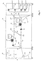
- a high-performance printer 10 is shown in FIG for fast printing of single sheets of paper.
- the high performance printer 10 includes a first, lower one Printing unit D1 and a second, upper printing unit D2. Both Printing units D1, D2 work according to the known electrographic Process with the same transfer printing speed.
- the Fixing devices are connected downstream of printing units D1, D2, schematically in Figure 1 by two pairs of rollers 12, 14th are indicated.
- Single sheets are transferred via a transport channel 27 fed to an input section 28.
- a paper output 30 is connected to the high-performance printer 10, which contains a plurality of output containers 32 to 36. Furthermore, two output channels 38, 40 are provided, via which Single sheets issued to further processing stations can be.
- the high-performance printer 10 gives the printed Cut sheets from the output section 42.
- Transport routes are located inside the high-performance printer 10 arranged for the transport of the single sheets through which different operating modes of the high-performance printer become.
- the printing units D1, D2 are transfer printing transport routes 44, 46 assigned, each by drives are set so that the single sheets fed to the Printing units D1, D2 have their transfer printing speed. Both Transfer printing transport paths 44, 46 are via a connecting channel 48 connected to each other.
- the transport route around the first Printing unit D1 is to a ring R1 through a feed channel 50 added, about which also single sheets from the input section 28 can be fed to the second transfer printing transport path 46.
- the transport route for the second printing unit D2 is similar Supplemented to form a ring R2 by a discharge channel 52, about the single sheets printed by the printing unit D1 Output section 42 can be supplied.
- first switch W1 arranged, which enables cut sheets from the input section 28 optionally the first transfer printing transport path 44 or be fed to the feed channel 50.
- Another variant is that on the feed channel 50 in the direction the switch W1 transported single sheets on the first transfer printing path 44 can be supplied.
- a second switch W2 and a third switch W3 arranged at the ends of the connecting channel 48 and connect the adjacent transport routes 44, 48, 52 or 46, 48, 50.
- a fourth turnout W4 is nearby of the output section 42 and connects the adjacent ones Transport routes.
- the paper output 30 contains a fifth switch W5, which works as a turning device. Furthermore is still to point to a control device 54, which via a Soft W6 reject single sheets are fed.
- duplex printing becomes the front and the back of the single sheets with different patterns Color printed.
- the printing units D1 and D2 different colors Can print images.
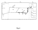
- Operating phase will be a group of six single sheets B1 to B6 via the input section 28 and the switch W1 (see FIG. 1 in each case) and along the first Transfer printing route 44 past the lower printing unit D1, the first page being indicated with a first color with dots.
- the first cut sheet B1 almost reaches the switch W2 and the connecting channel 48 has the last single sheet B6 Group still in or before the input section 28.
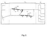
- Figure 3 shows that the leaves successively the connecting channel 48 and the second transfer printing route 46 are fed to the second printing unit D2 for printing.
- a higher transport speed than the transfer printing speed available to the cut sheets on the route between the two printing units D1, D2 in the shortest possible time Time to move.
- the single sheets B1 to B6 are again at transfer printing speed braked.
- the through the printing unit D1 already printed side another print with a different color, e.g. Red, angry.
- this second printing process is characterized by longitudinal lines.
- FIG 4 shows the operating phase in which the first single sheet B1 conveyed further after printing and at the switch W4 with turning function has been turned. After that, the Single sheets B1 to B6 one after the other along the discharge channel 52 promoted again in the direction of the first printing unit D1. To note that the sixth single sheet B6 is still in one sufficient safety distance before the first sheet B1 on the way towards connection channel 48.
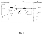
- FIG 5 shows the operating phase in which the sixth single sheet B6 is printed by the second printing unit D2, while the first single sheet B1 already connects the connecting channel 48 has passed through and is now conveyed along the feed channel 50 becomes. All single sheets B1 to B6 are on the Soft W4 turned.
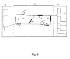
- Figure 6 shows the first single sheet B1 shortly before feeding to the first printing unit D1.
- the conveyor speed for that Cut sheet B1 is back on the transfer printing speed set.
- the other single sheets B2 to B6 are still conveyed at increased speed.
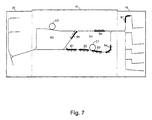
- Figure 7 shows that the single sheets B1 and B2 to the third times printed, i.e. the first printing unit prints the other side of the single sheets, illustrated in Figure 7 by dots.
- the sixth single sheet B6 is still in Connection channel 48, but has a sufficiently large safety distance from the following single sheet B1.
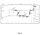
- Figure 8 shows the re-feeding of the single sheet B1 and of the further single sheets B2 to B6 of the first group for Printing unit D2.
- the fourth print is on this printing unit D2 applied.
- the single sheets B1 ', B2', B3 'of the following group on the switch W1 are fed to the first transfer printing transport path 44.
- the Distance between the last single sheet B6 of the first group and corresponds to the first single sheet B1 'of the second group the predetermined distance a of the single sheets at transfer speed.
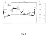
- Figure 9 shows an operating phase in which the first group from single sheets B1 to B6 through the second printing unit D2 printed (indicated by horizontal lines in Figure 9) and then via the output section 42 in the Paper output 30 transported and stored there.
- the second group of single sheets B1 'to B6' follows below already printed by the first printing unit D1.
- Another variant is the path of the group from To select single sheets differently, for example by using the Group first after the printing unit D2, then the printing unit D1 then turning again printing unit D2, then printing unit D1 fed and the single sheets through the discharge channel 52nd be issued.
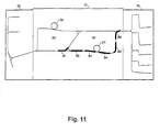
- Figure 10 is the feeding of the first group of single sheets B1 to B6 shown from the paper input 16 to the first printing unit D1, which the single sheets B1 to B6 with a first Color printed (shown with dots), e.g. with a black color.
- the feed speed can be higher than that Transfer speed, but this must be higher speed when reaching the first printing unit D1 the transfer speed can be reduced.
- Figure 11 shows the turning of the single sheets on the switch W2 (see FIG. 1), the single sheet B1 initially in the direction the switch W4 conveyed, then the transport direction reversed and the cut sheet B1 toward the connection channel 48 is transported.
- the switch W2 see FIG. 1
- the single sheet B1 initially in the direction the switch W4 conveyed then the transport direction reversed and the cut sheet B1 toward the connection channel 48 is transported.
- the cut sheet B1 toward the connection channel 48 is transported.
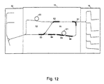
- Figure 12 shows that the cut sheets B1 to B6 along the first closed transport route R1 are promoted.
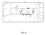
- Figure 13 shows the printing of the back of the single sheets B1 to B6 through the printing unit D1.
- Figure 14 shows the conveyance of the single sheets B1 to B6 over the connecting channel 48 to the second transport path 46, wherein no turning. On the right in FIG. 14 it can be seen that the single sheets B1 ', B2' of the group below the paper input 16 are already provided.
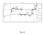
- Figure 15 shows the printing on one side of the single sheets B1 to B6 through the second printing unit D2.
- the first Printing unit D1 are already the single sheets of the following Group fed, i.e. the first single sheet B1 'of the following group follows the last single sheet B6 of the first group.
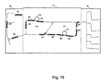
- Figure 16 shows the removal of the single sheets B1 to B6 the first group into paper output 30 with no turning and a so-called face-down storage takes place.
- the single sheets B1 'to B6' of the following group are in one Operating phase, as shown in Figure 11.
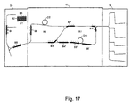
- Figure 17 shows the further storage of the single sheets B1 to B6 of the first group and printing on the single sheets B1 ' to B6 'of the group below.
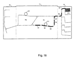
- FIGS Different operational phases are shown in FIGS shown with duplex printing with four printing, single sheets alternately the first transport ring R1 or the second transport ring R2 are fed.
- FIGS show with duplex printing with four printing, single sheets alternately the first transport ring R1 or the second transport ring R2 are fed.
- duplex printing becomes the front and the back of the single sheets with different patterns Color printed.
- the printing units D1 and D2 different colors Can print images.
- Operating phase will be a group of eleven single sheets B1 to B11 from paper input 16 through the input section 28 and the switch W1 (see FIG. 1) and along the first transfer printing path 44 at the bottom Printing unit D1 passed, the first page with a first color, indicated by dots, is printed. While the first single sheet B1 almost the switch W2 and the connecting channel 48 has reached, the last single sheet is B11 of the group before the input section 28 in the Paper input 16.
- Figure 19 shows that the cut sheets successively the connecting channel 48 pass through and on the second transfer printing route 46 fed to the second printing unit D2 for printing become.
- a higher transport speed than the transfer printing speed available to the cut sheets on the route between the two printing units D1, D2 in the shortest possible time Time to move.
- the single sheets B1 to B11 are again at transfer printing speed braked.
- the through the printing unit D1 already printed side another print with a different color, e.g. Red, angry.
- this second printing process is characterized by longitudinal lines.
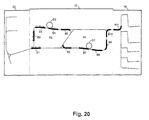
- Figure 20 shows the operating phase in which the first single sheet B1 conveyed further after printing and at the switch W4 with turning function has been turned. After that, the Single sheets B1 to B11 one after the other within the ring R2 along the discharge channel 52 again in the direction of the first Funded printing unit D1. It should be noted that the eleventh Single sheet B11 before the input section 28 in the unprinted Condition is and the single sheet B6 as well as the following single sheets B7, B8, B9 not yet the connecting channel 48 have gone through.
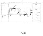
- Figure 21 shows an operating phase in which the first single sheet B1 on the switch W2 between the single sheets B6 and B7 is threaded and conveyed upward in the connecting channel 48 becomes.
- the single sheets B1 to B11 after leaving the printing unit D1 at higher speed conveyed as the transfer printing speed up to the printing unit D2.
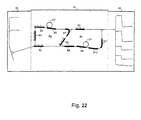
- Figure 22 shows the operating state in which the single sheet B1 after leaving the turn W3 towards the first Printing unit D1 is promoted.
- the single sheet B6 is against it have been promoted in the direction of the printing unit D2.
- the following Cut sheet B7 is just going through turnout W3 Printing unit D2 deflected.
- the single sheet B2 is between the single sheets B7 and B8 have been threaded and will be in Connection channel 48 promoted upwards.
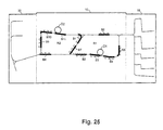
- Figure 23 shows the first single sheet B1 shortly before feeding to the first printing unit D1.
- the conveyor speed for that Cut sheet B1 is back on the transfer printing speed set.
- the other single sheets B2, B3, B4 in ring R1 are still being promoted at increased speed.
- the single sheet B4 is on the switch W3 between the single sheets B9 and B10 have been added.
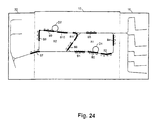
- Figure 24 shows that the single sheets B1 and B2 to the third times printed, i.e. the first printing unit D1 prints the other side of the single sheets, illustrated in Figure 8 by dots.
- the eleventh single sheet B11 is still in Connection channel 48 and is used for printing in the direction of the printing unit D2 redirected.
- the single sheet B6 is between the single sheets B11 and B1 inserted and is in the connecting channel 43 promoted upwards.
- Figure 25 shows the re-feeding of the single sheet B1 and the other single sheets B2 and the following sheets B3 to B11 of the first group for printing unit D2.
- the single sheet B7 is in the connecting channel 48 between the single sheets B1 and B2 inserted.
- FIG. 26 shows the operating phase in which a first part of the Single sheets B1, B2, B3 of the first group through the second Printing unit D2 is printed, indicated by horizontal lines.
- the single sheets B10 and B11 are in the manner of a Zipper system between the single sheets B4 and B5 or B5 and B6 inserted in the connecting channel 48.
- Figure 27 shows that those provided with a fourth printed image Single sheets, e.g. the single sheets B1, B2, about the Output section 42 promoted in the paper output 30 and be filed there.
- a subsequent group of single sheets B1 'to B11' is funded from paper input 16.
- the group of Single sheets B1 'to B11' then pass through the high-performance printer in the for the first group of single sheets B1 to B11 described manner.
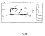
- Figure 28 shows the common transport of single sheets B3 to B11 of the first group and the single sheets B1 ', B2' and B3 'of the subsequent second group. Both printing units D1 and D2 are almost 100% fully occupied.
- Another variant is the path of the group from To select single sheets differently, for example by using the Group first after the printing unit D2, then the printing unit D1 then turning again printing unit D2, then printing unit D1 fed and the single sheets through the discharge channel 52nd be issued.
- the maximum number of single sheets in a group depends on the total length of the transport path in the printing system.
- the predetermined number of single sheets of a group results in where L 44 the length of the first transfer printing path 44, L 46 the length of the second transfer printing path 46, L 48 the length of the connecting channel 48, L 50 the length of the feed channel 50, L 52 the length of the discharge channel 52, L B the Length of the single sheet seen in the transport direction and a is the distance between two consecutive single sheets at transfer speed.
- Claim 19 describes a further calculation method for Find the maximum number of single sheets in a group. Threading the single sheets into the connecting channel 48 can be untriggered or triggered. With the untriggered The single sheets coming from ring R2 become the operating mode threaded into the connecting channel 48 without the cut sheets are stopped. With the aid of the Figures 1 and Figures 20 and 21 is said to be untriggered Operating mode are explained in more detail. As mentioned, it will EL single sheet B1 between the single sheets B6 and B7 in the connecting channel threaded and promoted up and then fed to the printer D1, while the cut sheets B6 and B7 are fed to the printing unit D2 (cf. FIGS. 20 and 21).
- the distance between size the single sheets from single sheet B6, that the single sheet B1 to be threaded at a defined speed is promoted on the transport route 52 and without stop threading between sheets B6 and B7 can.
- the speed of the single sheets the transport route from switch W4 to switch W6, where the speed is reduced again to transfer speed, remains approximately constant in this operating mode.
- Thread on the common path of the connecting channel 48 successively the single sheet B1 between the single sheets B6 and B7, the single sheet B2 between the single sheets B7 and B8, the single sheet B3 between the single sheets B8 and B9 and so on.
- the turnout W3 is when leaving the Cut sheets on each cut sheet to the successive Single sheets alternately the first or the to supply second printing unit D1 or D2.
- the single sheet B1 and the following single sheets will be about from turnout W6 to turnout W2 with transfer printing speed transported, on the printing unit D1 for the third time printed and thread between the single sheets B6 and B7 as well the following single sheets, which have a corresponding Distance from each other.
- After threading on the Soft W2 becomes the single sheets B1 and the following single sheets conveyed to the printing unit D2 at increased speed.
- the single sheets are optionally turned around them in one of the output trays 32, 34, 36 with the front at the bottom (face down) or face up.
- the last single sheet B11 has the first one Group of single sheets the common path in the connecting channel 48 happens and the first single sheet B1 'of following penalty group can be moved in.
- the current single sheets are closed.
- the application advantage lies in the unriggered operating mode in the fact that no special control effort when threading on the turnout W2 is required. Rather, the Return of the single sheets from the upper printing unit D2 to lower printing unit D1 at a constant speed.
- the disadvantage is that tolerances in the distances between the Single sheets within the group cannot be balanced can and so a jam can occur when threading.
- the triggered operating mode is explained below.
- 20 and 21 is that from the printing unit D2 to the printing unit D1 Single sheet B1 to be fed between the single sheets Thread B6 and B7 on the turnout W2.
- This mode is the distance between the single sheets B6 and B7 and the following single sheets are equal to the short nominal distance.
- the single sheet B1 is after leaving the Soft W4 with turning function with such great speed
- Direction of turnout W2 transports it early enough before the turnout W2 arrives, preferably before the single sheet 36 the switch W2 has passed. At this turnout W2 it is Sheet B1 stopped briefly or at speed slowed down. The further transport of the single sheet B1 is then triggered by cut sheet B6.
- the rear end of the cut sheet B6 Preferably at A signal leaves the rear end of the cut sheet B6 generates the transport of the single sheet B1 in the connecting channel 48 preferably at the same speed initiated, with which the single sheet B6 is also promoted.
- the single sheet B1 thus threads at the same increased speed between the single sheets B6 and B7 like the transport speed of the single sheet B6 in the connecting channel 48.
- the first pair of drive rollers reached in the connecting channel 48 this is Roller pair and also the following in the connecting channel 48 in its transport speed to transfer printing speed reduced because the single sheet B7 is still partially in the area of the first printing unit D1, for example in one Decurler. Accordingly, the single sheet B1 is also in its Speed to the speed of the cut sheet B7 reduced.
- the cut sheet B7 the printing area, preferably leaves the area of the decurler in the printing unit D1
- the single sheet B1 is then also at an increased speed transported forward and reaches the transport route 50.
- the single sheet B1 is increased with a constant Speed transported to the area on the turnout W6 and then reduced to transfer speed.
- the time to reduce the transport speed of sheet B1 can be on the preceding sheet B11 must be coordinated. Then the gap between the end of sheet B11 and the beginning of sheet B1 Nominal distance or slightly larger.
- the other single sheets B2, B3 etc. within the 911 group of single sheets are transported in a similar way, as described for single sheet B1 is.
- Threading on the turnout W2 This reduces the risk of traffic jams when threading and the distance between the single sheets can be minimized.
- a disadvantage is the increased control and Tax expense when threading.
- duplex printing has been described, a predetermined number of single sheets, preferably eleven, being combined into a group and this group being printed on both sides by the printing units D1 and D2. It is a - possible further, non-covered by the appended claims mode takes place in which no group-wise transport of the individual sheets, but a continuous supply of individual sheets.
- This operating mode is called a continuous operating mode. In this continuous operating mode, only every second single sheet is drawn in from the paper input 16, ie the distance between two successive single sheets drawn in is equal to the respective sheet length plus the nominal distance. The resulting gaps between the single sheets are filled in successively by leading single sheets that have already been printed twice. In this way, a continuous single sheet flow is generated and the printing units D1, D2 are used optimally.
Landscapes
- Physics & Mathematics (AREA)
- General Physics & Mathematics (AREA)
- Separation, Sorting, Adjustment, Or Bending Of Sheets To Be Conveyed (AREA)
- Handling Of Cut Paper (AREA)
- Counters In Electrophotography And Two-Sided Copying (AREA)
- Conveyance By Endless Belt Conveyors (AREA)
- Color Electrophotography (AREA)
Description
- Figur 1
- schematisch den Aufbau eines Hochleistungsdruckers, bei dem die Erfindung verwirklicht ist,
- Figuren 2 bis 9
- Betriebsphasen des Duplex-Druckbetriebs mit viermaligem Bedrucken,
- Figuren 10 bis 17
- Betriebsphasen des Duplex-Druckbetriebs mit dreimaligem Bedrucken, und
- Figuren 18 bis 28
- Betriebsphasen mit viermaligem Bedrucken und abwechselndem Zuführen von Einzelblättern dem ersten oder dem zweiten Transportring.

- 10
- Hochleistungsdrucker
- 12, 14
- Fixiereinrichtung
- 16
- Papiereingabe
- 18 - 24
- Vorratsbehälter
- 26
- Papiereingabekanal
- 27
- Transportkanal
- 28
- Eingabeabschnitt
- 30
- Papierausgabe
- 32 - 36
- Papierbehälter
- 38, 40
- Ausgabekanäle
- 42
- Ausgabeabschnitt
- 44
- erster Umdruck-Transportweg
- 46
- zweiter Umdruck-Transportweg
- 48
- Verbindungskanal
- 50
- Zuführkanal
- 52
- Abführkanal
- 54
- Aussteuereinrichtung
- W1 - W4
- Weichen
- R1
- erster geschlossener Transportweg (Ring)
- R2
- zweiter geschlossener Transportweg (Ring)
- D1
- erstes Druckwerk
- D2
- zweites Druckwerk
Claims (32)
- Verfahren zum Bedrucken von Einzelblättern in einem Drucker oder in einem Kopierer,bei dem eine vorbestimmte Zahl (N) von Einzelblättern zu einer Gruppe zusammengefaßt wird, wobei die Einzelblätter bei Umdruckgeschwindigkeit einen vorgegebenen Abstand (a) voneinander haben, der kleiner als die Länge eines Einzelblatts in Transportrichtung gesehen ist,die Einzelblätter dieser Gruppe einem ersten Druckwerk (D1) nacheinander zum Bedrucken mit einer ersten Farbe auf der ersten Seite zugeführt werden,danach die Einzelblätter der Gruppe einem zweiten Druckwerk (D2) nacheinander zum Bedrucken mit einer zweiten Farbe auf der ersten Seite zugeführt werden,und bei dem die Einzelblätter der Gruppe unter Wenden der Einzelblätter erneut dem ersten Druckwerk (D1) nacheinander zum Bedrucken mit der ersten Farbe auf der zweiten Seite zugeführt werden.
- Verfahren nach Anspruch 1, dadurch gekennzeichnet, daß die Einzelblätter der Gruppe dem zweiten Druckwerk (D2) zum Bedrucken mit der zweiten Farbe auf der zweiten Seite zugeführt und dann ausgegeben werden.
- Verfahren nach Anspruch 1 oder 2, dadurch gekennzeichnet, daß während des Transports der Gruppe der Einzelblätter der Abstand zwischen den Einzelblättern an den Druckwerken (D1, D2) im wesentlichen beibehalten wird.
- Verfahren nach einem der vorhergehenden Ansprüche 1 bis 3, dadurch gekennzeichnet, daß die Gruppe von Einzelblättern dem ersten Druckwerk (D1) von einem Eingabeabschnitt (28) über einen ersten Umdruck-Transportweg (44) zugeführt werden, an den sich ein Verbindungskanal (48) anschließt, über den die Einzelblätter einem zweiten Umdruck-Transportweg (46) für das zweite Druckwerk (D2) zugeführt wird, daß der zweite Umdruck-Transportweg (46) in einen Ausgabeabschnitt (42) mündet, daß zwischen Ausgabeabschnitt (42) und dem einen Ende des Verbindungskanals (48) ein Abführkanal (52) für den Transport der Einzelblätter vorgesehen ist, und daß zwischen dem Eingabeabschnitt (28) und dem anderen Ende des Verbindungskanals (48) ein Zuführkanal (50) angeordnet wird.
- Verfahren nach Anspruch 4, dadurch gekennzeichnet, daß die Gruppe von Einzelblättern zunächst den ersten Umdruck-Transportweg (44), dann den Verbindungskanal (48), den zweiten Umdruck-Transportweg (46), den Abführkanal (52), erneut den Verbindungskanal (48), den Zuführkanal (50), den ersten Umdruck-Transportweg (44), den Verbindungskanal (48) und den zweiten Umdruck-Transportweg (46) durchlaufen und dann am Ausgabeabschnitt (42) ausgegeben werden.
- Verfahren zum Bedrucken von Einzelblättern in einem Drucker oder in einem Kopierer,bei dem eine vorbestimmte Zahl (N) von Einzelblättern zu einer Gruppe zusammengefaßt wird, wobei die Einzelblätter bei Umdruckgeschwindigkeit einen vorgegebenen Abstand (a) voneinander haben, der kleiner als die Länge eines Einzelblatts in Transportrichtung gesehen ist,die Einzelblätter dieser Gruppe einem ersten Druckwerk (D1) nacheinander zum Bedrucken mit einer ersten Farbe auf der ersten Seite zugeführt werden,die Einzelblätter der Gruppe unter Wenden der Einzelblätter erneut dem ersten Druckwerk (D1) nacheinander zum Bedrucken mit der ersten Farbe auf der zweiten Seite zugeführt werden,und bei dem danach die Einzelblätter der Gruppe dem zweiten Druckwerk (D2) zum Bedrucken mit der zweiten Farbe auf der zweiten Seite zugeführt und dann ausgegeben werden.
- Verfahren nach Anspruch 6, dadurch gekennzeichnet, daß die Gruppe von Einzelblättern dem ersten Druckwerk (D1) von einem Eingabeabschnitt (28) über einen ersten Umdruck-Transportweg (44) zugeführt werden, an den sich ein Verbindungskanal (48) anschließt, über den die Einzelblätter einem zweiten Umdruck-Transportweg (46) für das zweite Druckwerk (D2) oder einem Zuführkanal (50) zugeführt werden, daß der zweite Umdruck-Transportweg (46) in einen Ausgabeabschnitt (42) mündet, daß zwischen Ausgabeabschnitt (42) und dem einen Ende des Verbindungskanals (48) ein Abführkanal (52) für den Transport der Einzelblätter vorgesehen ist, und daß zwischen dem Eingabeabschnitt (28) und dem anderen Ende des Verbindungskanals (48) der Zuführkanal (50) angeordnet wird.
- Verfahren nach Anspruch 7, dadurch gekennzeichnet, daß die Gruppe von Einzelblättern zunächst den ersten Umdruck-Transportweg (44), dann den Verbindungskanal (48), den Zuführkanal (50), erneut den ersten Umdruck-Transportweg (44), den Verbindungskanal (48) und dann den zweiten Umdruck-Transportweg (46) durchlaufen und am Ausgabeabschnitt (42) ausgegeben werden.
- Verfahren nach einem der vorhergehenden Ansprüche 1 bis 8, dadurch gekennzeichnet, daß der Eingabeabschnitt (28) eine erste Weiche (W1) enthält, die die Einzelblätter entweder vom Eingabeabschnitt (28) oder vom Zuführkanal (50) dem ersten Umdruck-Transportweg (44) zuführt.
- Verfahren nach einem der vorhergehenden Ansprüche, dadurch gekennzeichnet, daß an der Verbindungsstelle zwischen erstem Umdruck-Transportweg (44) und Verbindungskanal (48) sowie an der Verbindungsstelle von zweitem Umdruck-Transportweg (46) und Verbindungskanal (48) eine zweite bzw. dritte Weiche (W2, W3) angeordnet werden.
- Verfahren nach einem der vorhergehenden Ansprüche, dadurch gekennzeichnet, daß zwischen zweitem Umdruck-Transportweg (46) und Abführkanal (52) eine vierte Weiche (W4) angeordnet ist.
- Verfahren nach einem der vorhergehenden Ansprüche, dadurch gekennzeichnet, daß die zweite, die dritte und/oder die vierte Weiche (W2 bis W4) eine Wendefunktion erfüllt, bei der das Einzelblatt gewendet wird.
- Verfahren nach Anspruch 12, dadurch gekennzeichnet, daß zum Wenden des Einzelblattes dieses zunächst an der jeweiligen Weiche (W2, W3, W4) vorbei auf einem ersten Transportweg in einer Transportrichtung in einen Wendeabschnitt (42, 50) transportiert wird, daß danach- die Transportrichtung umgekehrt wird, und daß die Weiche (W2, W3, W4) das Einzelblatt zu einem zweiten Transportweg in der anderen Transportrichtung fördert.
- Verfahren nach einem der vorhergehenden Ansprüche, dadurch gekennzeichnet, daß nach dem zweimaligen Zuführen der Gruppe von Einzelblättern zu dem ersten Umdruck-Transportweg (44) anschließend an das letzte Einzelblatt der Gruppe das erste Einzelblatt einer nachfolgenden Gruppe von Einzelblättern zugeführt wird.
- Verfahren nach Anspruch 14, dadurch gekennzeichnet, daß der Wegabstand zwischen dem letzten Einzelblatt der vorhergehenden Gruppe von Einzelblättern und dem ersten Einzelblatt der nachfolgenden Gruppe annähernd dem vorbestimmten Abstand entspricht.
- Verfahren nach einem der Ansprüche 3 oder 7, dadurch gekennzeichnet, daß der erste Umdruck-Transportweg (44), der Verbindungskanal (48) und der Zuführkanal (50) einen ersten geschlossenen Transportweg (R1) bilden.
- Verfahren nach einem der Ansprüche 3 oder 7, dadurch gekennzeichnet, daß der zweite Umdruck-Transportweg (46), der Verbindungskanal (48) und der Abführkanal (52) einen zweiten geschlossenen Transportweg (R2) für Einzelblätter bilden.
- Verfahren nach Anspruch 16 und 17, dadurch gekennzeichnet, daß der erste geschlossene Transportweg (R1) und der zweite geschlossene Transportweg (R2) im wesentlichen gleich lang sind.
- Verfahren nach einem der Ansprüche 3 oder 7, dadurch gekennzeichnet, daß die vorbestimmte Zahl von Einzelblättern einer Gruppe sich ergibt zuwobei L44 die Länge des ersten Umdruck-Transportweges (44), L48 die Länge des Verbindungskanals, L50 die Länge des Zuführkanals (50), LB die Länge des Einzelblattes in Transportrichtung gesehen und a der Abstand zwischen zwei aufeinanderfolgenden Einzelblättern bei Umdruckgeschwindigkeit ist.

- Verfahren nach einem der vorhergehenden Ansprüche, dadurch gekennzeichnet, daß für Einzelblätter im DIN A4 Format mit der kurzen Seite in Transportrichtung die Zahl N gleich 6 und für die längere Seite in Transportrichtung die Zahl N gleich 3 ist.
- Verfahren nach einem der vorhergehenden Ansprüche 1 bis 20, dadurch gekennzeichnet, daß jedes Druckwerk (D1 oder D2) einen Transportweg in Form eines Ringes (R1 oder R2) hat, die durch einen Verbindungskanal (48) miteinander verbunden sind, und bei dem im Verbindungkanal (48) zumindest ein Teil der Einzelblätter der Gruppe abwechselnd dem ersten Ring (R1) und dem zweiten Ring (R2) zugefördert wird.
- Verfahren nach Anspruch 21, dadurch gekennzeichnet, daß im Verbindungskanal (48) das abwechselnde Zufördern der Einzelblätter zu den Ringen (R1, R2) und/oder das Transportieren der Einzelblätter bis in die Nähe der Druckwerke (D1, D2) mit gegenüber der Umdruckgeschwindigkeit der Druckwerke (D1, D2) erhöhter Geschwindigkeit erfolgt.
- Verfahren nach Anspruch 21 oder 22, dadurch gekennzeichnet, daß der Verbindungskanal (48) Teil beider Ringe (R1, R2) ist und Einzelblätter in nur einer Richtung fördert.
- Verfahren nach einem der vorhergehenden Ansprüche 21 bis 23, dadurch gekennzeichnet, daß nach dem erneuten Vorbeilauf der Einzelblätter der Gruppe am ersten Druckwerk (D1) diese ausgegeben werden oder die Einzeiblätter dem zweiten Druckwerk (D2) zum Bedrucken mit der zweiten Farbe auf der zweiten Seite zugeführt und dann ausgegeben werden.
- Verfahren nach einem der vorhergehenden Ansprüche, dadurch gekennzeichnet, daß während des Transports der Gruppe der Einzelblätter der Abstand zwischen den Einzelblättern an den Druckwerken (D1, D2) im wesentlichen beibehalten wird.
- Verfahren nach einem der Ansprüche 3 oder 7, dadurch gekennzeichnet, daß die Gruppe von Einzelblättern zunächst den ersten Umdruck-Transportweg (44), dann den Verbindungskanal (48), den zweiten Umdruck-Transportweg (46), den Abführkanal (52), erneut den Verbindungskanal (48), den Zuführkanal (50), den ersten Umdruck-Transportweg (44) durchläuft und dann am Ausgabeabschnitt (42) ausgegeben wird.
- Verfahren nach einem der Ansprüche 3 oder 7, dadurch gekennzeichnet, daß die vorbestimmte Zahl von Einzelblättern einer Gruppe sich ergibt zuwobei L44 die Länge des ersten Umdruck-Transportweges (44), L46 die Länge des zweiten Umdruck-Transportweges (46), L48 die Länge des Verbindungskanals (48), L50 die Länge des Zuführkanals (50), L52 die Länge des Abführkanals (52), LB die Länge des Einzelblattes in Transportrichtung gesehen und a der Abstand zwischen zwei aufeinanderfolgenden Einzelblättern bei Umdruckgeschwindigkeit ist.

- Verfahren nach einem der vorhergehenden Ansprüche 21 bis 27, dadurch gekennzeichnet, daß für Einzelblätter im DIN A4 Format mit der kurzen Seite in Transportrichtung die Zahl N gleich 11 ist.
- Verfahren nach einem der vorhergehenden Ansprüche 21 bis 28, dadurch gekennzeichnet, daß bei einer ungetriggerten Betriebsart die einzufädelnden Einzelblätter des einen Rings (R2) dem Verbindungskanal (48) mit konstanter Geschwindigkeit zugeführt und mit dieser konstanten Geschwindigkeit zwischen Einzelblätter, die vom anderen Ring (R1) herkomen, eingefädelt werden.
- Verfahren nach Anspruch 29, dadurch gekennzeichnet, daß die Einzelblätter auf Transportwegen von der vierten Weiche (W4) bis zur sechsten Weiche (W6) mit annähernd konstanter Geschwindigkeit transportiert werden.
- Verfahren nach einem der vorhergehenden Ansprüche 21 bis 30, dadurch gekennzeichnet, daß bei einer getriggerten Betriebsart der Transport der einzufädelnden Einzelblätter des einen Rings (R2) abhängig von der aktuellen Lage mindestens eines der Einzelblätter erfolgt, zwischen die eingefädelt wird.
- Verfahren nach Anspruch 31, dadurch gekennzeichnet, daß das einzufädelnde Einzelblatt vor dem Zugang zum Verbindungskanal in seiner Geschwindigkeit verlangsamt oder angehalten wird.
Priority Applications (1)
| Application Number | Priority Date | Filing Date | Title |
|---|---|---|---|
| EP01122470A EP1174772B1 (de) | 1998-03-31 | 1999-03-31 | Verfahren und Gerät zum Bedrucken von Einzelblättern in Gruppen nach dem Duplexverfahren |
Applications Claiming Priority (5)
| Application Number | Priority Date | Filing Date | Title |
|---|---|---|---|
| DE19814384 | 1998-03-31 | ||
| DE19814384 | 1998-03-31 | ||
| DE19836746 | 1998-08-13 | ||
| DE19836746 | 1998-08-13 | ||
| PCT/EP1999/002232 WO1999050715A1 (de) | 1998-03-31 | 1999-03-31 | Verfahren zum bedrucken von einzelblättern in gruppen nach dem duplexverfahren |
Related Child Applications (1)
| Application Number | Title | Priority Date | Filing Date |
|---|---|---|---|
| EP01122470A Division EP1174772B1 (de) | 1998-03-31 | 1999-03-31 | Verfahren und Gerät zum Bedrucken von Einzelblättern in Gruppen nach dem Duplexverfahren |
Publications (2)
| Publication Number | Publication Date |
|---|---|
| EP1068560A1 EP1068560A1 (de) | 2001-01-17 |
| EP1068560B1 true EP1068560B1 (de) | 2002-04-10 |
Family
ID=26045156
Family Applications (2)
| Application Number | Title | Priority Date | Filing Date |
|---|---|---|---|
| EP01122470A Expired - Lifetime EP1174772B1 (de) | 1998-03-31 | 1999-03-31 | Verfahren und Gerät zum Bedrucken von Einzelblättern in Gruppen nach dem Duplexverfahren |
| EP99917943A Expired - Lifetime EP1068560B1 (de) | 1998-03-31 | 1999-03-31 | Verfahren zum bedrucken von einzelblättern in gruppen nach dem duplexverfahren |
Family Applications Before (1)
| Application Number | Title | Priority Date | Filing Date |
|---|---|---|---|
| EP01122470A Expired - Lifetime EP1174772B1 (de) | 1998-03-31 | 1999-03-31 | Verfahren und Gerät zum Bedrucken von Einzelblättern in Gruppen nach dem Duplexverfahren |
Country Status (5)
| Country | Link |
|---|---|
| US (2) | US6259884B1 (de) |
| EP (2) | EP1174772B1 (de) |
| JP (1) | JP4456757B2 (de) |
| DE (2) | DE59901193D1 (de) |
| WO (1) | WO1999050715A1 (de) |
Families Citing this family (21)
| Publication number | Priority date | Publication date | Assignee | Title |
|---|---|---|---|---|
| EP1174772B1 (de) * | 1998-03-31 | 2006-08-09 | Océ Printing Systems GmbH | Verfahren und Gerät zum Bedrucken von Einzelblättern in Gruppen nach dem Duplexverfahren |
| DE19958295A1 (de) * | 1999-12-03 | 2001-06-13 | Weitmann & Konrad Fa | Druckvorrichtung und Befeuchtungsstation für eine Druckvorrichtung |
| US6381440B1 (en) * | 2000-10-26 | 2002-04-30 | OCé PRINTING SYSTEMS GMBH | Printing system having at least three printer devices as well as method for the operation of such a printing system |
| DE10212840A1 (de) * | 2002-03-22 | 2003-10-09 | Oce Printing Systems Gmbh | Verfahren und Einrichtung zum Bedrucken von Einzelblättern mit einer Wendevorrichtung |
| US6669190B1 (en) * | 2002-07-12 | 2003-12-30 | Lite-On Technology Corporation | Double-side automatic feeding apparatus |
| US6980762B2 (en) * | 2003-12-19 | 2005-12-27 | Xerox Corporation | Modular multi-stage fusing system |
| US8488184B2 (en) * | 2004-03-18 | 2013-07-16 | Riso Kagaku Corporation | Image forming apparatus having a plurality of individually controlled recording heads |
| US7486421B2 (en) * | 2004-08-16 | 2009-02-03 | Lite-On Technology Corporation | Media transfer mechanism |
| US7324779B2 (en) | 2004-09-28 | 2008-01-29 | Xerox Corporation | Printing system with primary and secondary fusing devices |
| US7672634B2 (en) * | 2004-11-30 | 2010-03-02 | Xerox Corporation | Addressable fusing for an integrated printing system |
| JP4720161B2 (ja) * | 2004-12-01 | 2011-07-13 | セイコーエプソン株式会社 | 複合処理装置及びその制御方法 |
| US7731184B2 (en) * | 2005-07-15 | 2010-06-08 | Hewlett-Packard Development Company, L.P. | Duplexer |
| US7430380B2 (en) * | 2005-09-23 | 2008-09-30 | Xerox Corporation | Printing system |
| DE102006025454B4 (de) | 2006-05-31 | 2013-12-12 | Océ Printing Systems GmbH & Co. KG | Druck- oder Kopiersystem zum Verarbeiten von Einzelblättern mit Bestimmung des kürzestmöglichen Einzugsabstands und Verfahren zum Steuern eines solchen Druck- oder Kopiersystems |
| JP5366428B2 (ja) * | 2007-07-23 | 2013-12-11 | 理想科学工業株式会社 | 両面印刷装置 |
| WO2013163748A1 (en) * | 2012-05-03 | 2013-11-07 | Delphax Technologies Canada Ltd. | Inkjet printer with selectable simplex and duplex printing |
| JP6167819B2 (ja) * | 2013-10-02 | 2017-07-26 | 富士ゼロックス株式会社 | 画像形成装置 |
| DE102015017156B4 (de) | 2015-04-30 | 2023-11-30 | Koenig & Bauer Ag | Verfahren zum Betrieb einer Transporteinrichtung zum Transport von Bogen in einer Anordnung von mehreren jeweils Bogen bearbeitenden Bearbeitungsstationen |
| DE102015208050A1 (de) * | 2015-04-30 | 2016-11-03 | Koenig & Bauer Ag | Verfahren zum Betrieb einer Transporteinrichtung zum Transport von Bogen in einer Anordnung von mehreren jeweils Bogen bearbeitenden Bearbeitungsstationen |
| US9370940B1 (en) * | 2015-09-10 | 2016-06-21 | Xerox Corporation | Single decurler configuration for reduced contamination of decurler |
| JP7487004B2 (ja) * | 2020-05-18 | 2024-05-20 | キヤノン株式会社 | 画像形成装置 |
Family Cites Families (26)
| Publication number | Priority date | Publication date | Assignee | Title |
|---|---|---|---|---|
| US4591884A (en) | 1983-03-10 | 1986-05-27 | Canon Kabushiki Kaisha | Multi-function image recording apparatus |
| DE3422942A1 (de) * | 1983-06-22 | 1985-01-10 | Canon K.K., Tokio/Tokyo | Bilderzeugungsgeraet |
| JP2529222B2 (ja) * | 1986-10-27 | 1996-08-28 | 株式会社リコー | 両面記録装置 |
| JPS63246754A (ja) * | 1987-04-01 | 1988-10-13 | Minolta Camera Co Ltd | 画像作成装置 |
| US4943832A (en) | 1988-06-09 | 1990-07-24 | Minolta Camera Kabushiki Kaisha | Image forming apparatus |
| JP2815154B2 (ja) * | 1988-08-31 | 1998-10-27 | 株式会社リコー | 画像形成装置 |
| US5049946A (en) * | 1988-10-17 | 1991-09-17 | Kabushiki Kaisha Toshiba | Base for supporting an image forming apparatus, and function-adding device for combination therewith |
| DE4002785A1 (de) | 1989-02-01 | 1990-08-02 | Ricoh Kk | Verfahren zum erzeugen beidseitiger kopien in einer bilderzeugungseinrichtung |
| JP2656630B2 (ja) * | 1989-08-31 | 1997-09-24 | キヤノン株式会社 | 両面印字用搬送路を備える画像形成装置 |
| JPH05506725A (ja) | 1990-02-26 | 1993-09-30 | オーセ プリンテイング システムズ ゲゼルシャフト ミット ベシュレンクテル ハフツング | モジュールとして構成された電子写真式印刷装置 |
| JPH0466423A (ja) * | 1990-07-05 | 1992-03-02 | Minolta Camera Co Ltd | 画像作成装置 |
| JPH0498266A (ja) * | 1990-08-17 | 1992-03-30 | Ricoh Co Ltd | 電子写真式画像形成装置 |
| JPH04119866A (ja) * | 1990-09-10 | 1992-04-21 | Minolta Camera Co Ltd | 画像作成装置 |
| US5159395A (en) * | 1991-08-29 | 1992-10-27 | Xerox Corporation | Method of scheduling copy sheets in a dual mode duplex printing system |
| US5184185A (en) * | 1991-08-29 | 1993-02-02 | Xerox Corporation | Method for duplex printing scheduling system combining finisher interset skipped pitches with duplex sheet scheduling |
| JPH0591263A (ja) * | 1991-09-26 | 1993-04-09 | Oki Electric Ind Co Ltd | スキヤナ付き印刷装置 |
| US5499091A (en) * | 1993-04-19 | 1996-03-12 | Canon Kabushiki Kaisha | Image forming apparatus having a counting device to facilitate two-sided copying |
| US5449166A (en) * | 1993-05-06 | 1995-09-12 | Licentia Patent-Verwaltungs-Gmbh | Apparatus for reversing the direction of flat items |
| US5337135A (en) * | 1993-09-30 | 1994-08-09 | Xerox Corporation | Higher productivity trayless duplex printer with variable path velocity |
| JPH08286525A (ja) * | 1995-04-14 | 1996-11-01 | Fuji Xerox Co Ltd | 画像形成装置 |
| JP2814964B2 (ja) * | 1995-09-21 | 1998-10-27 | 日本電気株式会社 | プリンタ装置 |
| US5568246A (en) * | 1995-09-29 | 1996-10-22 | Xerox Corporation | High productivity dual engine simplex and duplex printing system using a reversible duplex path |
| US5598257A (en) | 1995-09-29 | 1997-01-28 | Xerox Corporation | Simplex and duplex printing system using a reversible duplex path |
| US6112047A (en) * | 1996-03-11 | 2000-08-29 | Ricoh Company, Ltd. | Image forming apparatus having a substantially vertical sheet transport path and a relaying mechanism that cooperate to transfer a sheet to a sheet discharge section |
| WO1998018054A1 (de) * | 1996-10-22 | 1998-04-30 | Oce Printing Systems Gmbh | Verfahren zum betreiben eines druckers mit zwei druckwerken |
| EP1174772B1 (de) * | 1998-03-31 | 2006-08-09 | Océ Printing Systems GmbH | Verfahren und Gerät zum Bedrucken von Einzelblättern in Gruppen nach dem Duplexverfahren |
-
1999
- 1999-03-31 EP EP01122470A patent/EP1174772B1/de not_active Expired - Lifetime
- 1999-03-31 EP EP99917943A patent/EP1068560B1/de not_active Expired - Lifetime
- 1999-03-31 US US09/647,432 patent/US6259884B1/en not_active Expired - Fee Related
- 1999-03-31 WO PCT/EP1999/002232 patent/WO1999050715A1/de active Search and Examination
- 1999-03-31 DE DE59901193T patent/DE59901193D1/de not_active Expired - Lifetime
- 1999-03-31 DE DE59913765T patent/DE59913765D1/de not_active Expired - Lifetime
- 1999-03-31 JP JP2000541564A patent/JP4456757B2/ja not_active Expired - Fee Related
-
2001
- 2001-06-08 US US09/877,425 patent/US6647239B2/en not_active Expired - Fee Related
Also Published As
| Publication number | Publication date |
|---|---|
| JP2002510068A (ja) | 2002-04-02 |
| EP1068560A1 (de) | 2001-01-17 |
| EP1174772A2 (de) | 2002-01-23 |
| EP1174772A3 (de) | 2002-12-04 |
| EP1174772B1 (de) | 2006-08-09 |
| DE59901193D1 (de) | 2002-05-16 |
| US6259884B1 (en) | 2001-07-10 |
| JP4456757B2 (ja) | 2010-04-28 |
| DE59913765D1 (de) | 2006-09-21 |
| WO1999050715A1 (de) | 1999-10-07 |
| US6647239B2 (en) | 2003-11-11 |
| US20020081120A1 (en) | 2002-06-27 |
Similar Documents
| Publication | Publication Date | Title |
|---|---|---|
| EP1068560B1 (de) | Verfahren zum bedrucken von einzelblättern in gruppen nach dem duplexverfahren | |
| EP0977095B1 (de) | Drucker mit zwei Druckwerken | |
| DE19781182B4 (de) | Druck- oder Kopiersystem mit zwei Druckwerken und Verfahren zum Betreiben eines solchen Druck- oder Kopiersystems | |
| DE69406638T2 (de) | Hochgeschwindigkeitsdrucker | |
| DE19714951C2 (de) | Druckmaschine | |
| EP0937282B1 (de) | Drucker mit zwei druckwerken und durch schrittmotore angetriebene transportwalzenpaare | |
| EP0089407B1 (de) | Vorrichtung zum Aufteilen eines Stromes aus Druckexemplaren | |
| DE4443031A1 (de) | Transportsystem für ein Wellpappenblatt in einer Drucklinie | |
| DE3941315A1 (de) | Vorrichtung zum vermeiden einer schieflage geschnittener papierbogen | |
| DE69902970T2 (de) | Vorrichtung zum Sammeln von Bögen | |
| DE69431466T2 (de) | Mechanismus für beidseitiges Drucken und Verfahren dafür | |
| WO2007080100A1 (de) | Vorrichtung zum umlenken von blattgut | |
| DE60112531T2 (de) | Verfahren und Vorrichtung zum Fördern von Gegenständen | |
| DE2026050A1 (de) | Verfahren zum Herstellen mehrerer Bahn einheiten | |
| DE4130565C1 (en) | Photographic paper distribution system - uses slide travelling at right-angles to transport system of paper sheets | |
| EP0759360B1 (de) | Verfahren zur Steuerung einer Druckeinrichtung | |
| DE102004002645A1 (de) | Verfahren und Steuerungseinrichtung zum Transportieren von Bedruckstoff | |
| DE19915506A1 (de) | Verfahren und Vorrichtung zum Zuführen einer Reihe von Flachkörpern zu einem Stapel | |
| EP1055625A2 (de) | Vorrichtung und Verfahren zum Umlenken von Bedruckstoffbogen | |
| DE102011082447B4 (de) | Vorrichtung und Verfahren zum Zusammenführen von Gütern | |
| DE10328803A1 (de) | Vorrichtung zur unterbrechungsfreien Zufuhr von zu bearbeitenden Stücken zu einer Verarbeitungsmaschine, insbesondere Zufuhr von Bogen zu einer Druckmaschine | |
| EP0696364A1 (de) | Einzelblatt-zuführeinrichtung für ein elektrografisches druck- oder kopiergerät | |
| DE10326080A1 (de) | Druckstraße mit Bahnspeichereinheit und Nachverarbeitungssystem | |
| EP2390214B1 (de) | Verfahren zum Betrieb einer Einrichtung für den Transport von Druckerzeugnissen | |
| DE19649294C2 (de) | Falzapparat zur Herstellung von Buchsektionen |
Legal Events
| Date | Code | Title | Description |
|---|---|---|---|
| PUAI | Public reference made under article 153(3) epc to a published international application that has entered the european phase |
Free format text: ORIGINAL CODE: 0009012 |
|
| 17P | Request for examination filed |
Effective date: 20001025 |
|
| AK | Designated contracting states |
Kind code of ref document: A1 Designated state(s): DE FR GB |
|
| GRAG | Despatch of communication of intention to grant |
Free format text: ORIGINAL CODE: EPIDOS AGRA |
|
| 17Q | First examination report despatched |
Effective date: 20010517 |
|
| GRAG | Despatch of communication of intention to grant |
Free format text: ORIGINAL CODE: EPIDOS AGRA |
|
| GRAH | Despatch of communication of intention to grant a patent |
Free format text: ORIGINAL CODE: EPIDOS IGRA |
|
| GRAH | Despatch of communication of intention to grant a patent |
Free format text: ORIGINAL CODE: EPIDOS IGRA |
|
| REG | Reference to a national code |
Ref country code: GB Ref legal event code: IF02 |
|
| GRAA | (expected) grant |
Free format text: ORIGINAL CODE: 0009210 |
|
| AK | Designated contracting states |
Kind code of ref document: B1 Designated state(s): DE FR GB |
|
| REF | Corresponds to: |
Ref document number: 59901193 Country of ref document: DE Date of ref document: 20020516 |
|
| GBT | Gb: translation of ep patent filed (gb section 77(6)(a)/1977) |
Effective date: 20020708 |
|
| PLBE | No opposition filed within time limit |
Free format text: ORIGINAL CODE: 0009261 |
|
| STAA | Information on the status of an ep patent application or granted ep patent |
Free format text: STATUS: NO OPPOSITION FILED WITHIN TIME LIMIT |
|
| 26N | No opposition filed |
Effective date: 20030113 |
|
| PGFP | Annual fee paid to national office [announced via postgrant information from national office to epo] |
Ref country code: FR Payment date: 20120403 Year of fee payment: 14 |
|
| PGFP | Annual fee paid to national office [announced via postgrant information from national office to epo] |
Ref country code: GB Payment date: 20120327 Year of fee payment: 14 |
|
| PGFP | Annual fee paid to national office [announced via postgrant information from national office to epo] |
Ref country code: DE Payment date: 20120530 Year of fee payment: 14 |
|
| GBPC | Gb: european patent ceased through non-payment of renewal fee |
Effective date: 20130331 |
|
| REG | Reference to a national code |
Ref country code: FR Ref legal event code: ST Effective date: 20131129 |
|
| REG | Reference to a national code |
Ref country code: DE Ref legal event code: R119 Ref document number: 59901193 Country of ref document: DE Effective date: 20131001 |
|
| PG25 | Lapsed in a contracting state [announced via postgrant information from national office to epo] |
Ref country code: GB Free format text: LAPSE BECAUSE OF NON-PAYMENT OF DUE FEES Effective date: 20130331 Ref country code: DE Free format text: LAPSE BECAUSE OF NON-PAYMENT OF DUE FEES Effective date: 20131001 Ref country code: FR Free format text: LAPSE BECAUSE OF NON-PAYMENT OF DUE FEES Effective date: 20130402 |