EP1065166A2 - Teleskopkran - Google Patents
Teleskopkran Download PDFInfo
- Publication number
- EP1065166A2 EP1065166A2 EP00250210A EP00250210A EP1065166A2 EP 1065166 A2 EP1065166 A2 EP 1065166A2 EP 00250210 A EP00250210 A EP 00250210A EP 00250210 A EP00250210 A EP 00250210A EP 1065166 A2 EP1065166 A2 EP 1065166A2
- Authority
- EP
- European Patent Office
- Prior art keywords
- boom
- crane according
- telescopic crane
- guy
- telescopic
- Prior art date
- Legal status (The legal status is an assumption and is not a legal conclusion. Google has not performed a legal analysis and makes no representation as to the accuracy of the status listed.)
- Granted
Links
Images


Classifications
-
- B—PERFORMING OPERATIONS; TRANSPORTING
- B66—HOISTING; LIFTING; HAULING
- B66C—CRANES; LOAD-ENGAGING ELEMENTS OR DEVICES FOR CRANES, CAPSTANS, WINCHES, OR TACKLES
- B66C23/00—Cranes comprising essentially a beam, boom, or triangular structure acting as a cantilever and mounted for translatory of swinging movements in vertical or horizontal planes or a combination of such movements, e.g. jib-cranes, derricks, tower cranes
- B66C23/62—Constructional features or details
- B66C23/82—Luffing gear
- B66C23/821—Bracing equipment for booms
- B66C23/826—Bracing equipment acting at an inclined angle to vertical and horizontal directions
- B66C23/828—Bracing equipment acting at an inclined angle to vertical and horizontal directions where the angle is adjustable
Definitions
- the invention relates to a telescopic crane consisting of an undercarriage, a Upper carriage rotatably arranged on it, a counterweight and a boom according to the preamble of claim 1.
- Telescopic cranes with superlift operation have been known for a long time (see excerpt Company brochure Mannesmann Demag printechnik; Demag AC 1600; 04/96, pages 5, 17 and 27).
- To increase the load and reduce the deflection of the extended main boom is on the main boom of the main boom on the Base box removable guy stand arranged with an almost length-fixed guying with the foot area of the main boom on the one hand and with a further guying, which is usually adjustable in length, with the head or collar of one of the inner telescopic sections on the other connected.
- This stiffening arrangement is applicable to the basic device alone, but also in connection with the arrangement of one formed from lattice tower parts rigid or luffing jib.
- the object of the invention is to provide a telescopic crane, the lateral Deformation of the boom, especially in the steep position, is significantly less than at known telescopic cranes.
- At least one is opposite to the boom Rocker plane inclined guy support arranged with a substantially in Longitudinal direction of the boom extending clamping means is connected, the The angle of the guy support is selected so that it acts on the boom lateral or partial load is absorbed by the guying becomes.
- the inclination of the guy support can be transverse to the longitudinal direction or in Longitudinal direction or superimposed transversely to and in the longitudinal direction of the boom.
- both Guy braces are provided, usually the angular inclination of both Guy supports are the same.
- the foot ends of both guy supports can be connected to the top of the boom at a common location, but also offset from each other.
- the foot end of at least one guy support in the transition area between Top side or respective side wall connected to the boom.
- there is also the possibility to cross the foot end of at least one guy support To arrange the longitudinal axis of the boom and overhanging this beam.
- the proposed arrangement has the advantage that, depending on the angular position Guy supports: the amount of guy force that acts in the lateral direction can be changed continuously or continuously.
- the two guy supports in parallel are the same Effect in the sense of a superlift operation like the well-known guy stand.
- ⁇ 90 ° to> 0 ° for the two guy supports becomes the effective one Clamping force divided into a superlift operation component and a component lateral guying.
- the two guy supports In the second extreme position, i.e. H. in the horizontal position, the two guy supports only reinforce in both directions.
- the respective free head end of the guy support is over a first clamping device optionally with the undercarriage, the uppercarriage, the foot area of the boom, the fixed or separately guided counterweight or the floor in the direction Foot end of the boom and a further clamping device with a selected one Place the boom connected in the direction of the boom head.
- the one you want Angular position of the guy supports can be gradual or continuous Swiveling the guy supports can be adjusted. So that's one asymmetrical angle adjustment possible. This means that when attacking Lateral force only on one side the respective guy support more towards the side Guy is inclined while the second guy support is in a central position remains.
- the clamping devices can be used as a rope or as a rod be trained.
- the clamping device or the clamping device can be with and without Preload can be arranged. In the case of a preload and one
- the clamping device can be adjusted with a clamping device together. This is preferably a winch or a piston-cylinder unit. But also the angle adjustment and / or the change in length of the guy support can in Can be used as a tensioning device.
- the jigs are either on the guy supports, on the boom, on the superstructure or undercarriage or on Counterweight can be arranged.
- the guy supports on the main boom are preferably in the area of the Basic box arranged, especially in the front area between the Linkage of the luffing cylinder and the front bearing.
- For continuous Adjustment of the guy supports is preferably every guy support with one on the piston-cylinder unit supported on the basic box.
- the equipment of the telescopic boom can be supplemented with the arrangement a rigid or luffing jib made of lattice boom parts. Also on the proposed lateral bracing can be attached to these cantilever elements become.
- the side guying can be used particularly effectively if the Crane with a measuring device to record the lateral deformation of the boom is provided. If the deformation exceeds a specified permissible value, the tensioning device connected to the guying is activated and the guying tightened.
- the degree of lateral deformation can be direct or indirect Crane sizes can be determined. For example, these are the rope tension, the rope length and rope elongation. But also about the forces acting on the boom in form the side wind, the sun and the boom prevailing temperatures can make a statement about the degree of lateral Deformation can be made.
- FIGS. 1a-c the possible arrangement of one another is shown as a basic sketch the guy support inclined to the luffing plane.
- the guy support 2 is preferably on the top 3 of a symbolically shown here Cantilever element 1 arranged.
- This boom element 1 can be a basic box or a shot from a main boom of a telescopic crane or that Lattice mast element of a rigid or luffing jib.
- the in Cantilever element 1 drawn center axis 4 is ideally the luffing plane of the boom.
- the guy support 2 is in relation to the luffing plane in inclined at an angle ⁇ > 0.
- the dashed representation of the guy support 2 ' should make it clear that the guy support 2 can also be tilted towards the other side.
- the free end 5 of the guy support 2 is preferably with a clamping means 6.7 connected to a rope.
- the connection of the clamping means 6, 7 is not shown here a fixed location on the boom or a clamping device such as Piston cylinder unit or winch.
- a clamping of the clamping means 6.7 can be done can also be reached without a clamping device. Firstly, in such a way that the clamping device 6.7 can be arranged at a smaller or larger angle ⁇ and then the Guy support 2 is further inclined. Alternatively, it is also possible to use the guy support 2 telescopic and a degree of tension by changing the length to reach.
- FIG 2 is also a schematic diagram of the arrangement of two guy supports 2.1, 2.2 shown.
- the peculiarity of this arrangement is that both Guy supports 2.1,2.2 with only a single foot end 8 on the top 3 of the Cantilever element 1 are arranged.
- the respective angle of inclination ⁇ 1, ⁇ 2 can be the same or different.
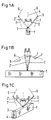
- partial images a-d of FIG. 3 the possibility of is also shown as a schematic diagram Arrangement of two guy supports 2.1.2.2 shown, which have a separate foot end 8.1.8.2 have.
- the foot ends 8.1, 8.2 are in the area the top 3 of the cantilever element 1, while in the sub-picture b the foot ends 8.1,8.2 in the transition area from the top 3 to the respective side wall 9, 9 ' are located.
- sub-picture c the possibility is shown at least one foot end 8.1 outside to arrange the boom element 1.
- there is a here on top 3 Set-up aid each provided a piston-cylinder unit 28.1.28.2, which at one end the side wall 25 and with the other end in half the area of the respective Guy support 18.1 is arranged.
- the tensioning means each with a rope 29.1, is at one end via a rope thimble 31.1 Head area of the guy support 18.1 attached. From there it runs towards Boom head arranged deflection point (also not shown here) and runs back via a deflection roller 30.1 and. arranged in the head region of the guy support 18.1 thence to the winch 27.1.
- a guy clip 32.1 is arranged, which represents the rear securing for the respective guy support 18.1.
Abstract
Description
- Fig. 1a-1c
- als Prinzipskizze die mögliche Anordnung einer gegenüber der Wippebene geneigten Abspannstütze
- Figur 2
- als Prinzipskizze die Anordnung zweier geneigter Abspannstützen mit einem gemeinsamen Fußende.
- Figur3a-3d
- als Prinzipskizze die mögliche Anordnung zweier geneigter Abspannstützen mit getrennten Fußenden
- Figur 4
- als Prinzipskizze die Anordnung einer quer liegenden Abspannstütze
- Figur 5a
- in einer Vorderansicht ein praktisches Ausführungsbeispiel mit zwei neigbaren Abspannstützen.
- Figur 5b
- eine Seitenansicht von Figur 5a.
| Bezugszeichliste | |
| Nr. | Bezeichung |
| 1 | Auslegerelement |
| 2,2' | Abspannstütze |
| 3 | Oberseite Auslegerelement |
| 4 | Mittellinie-Wippebene |
| 5 | Freies Ende Abspannstütze |
| 6,7 | Spannmittel |
| 8 | Fußende |
| 9,9' | Seitenwand Auslegerelement |
| 10,11,12 | Träger |
| 13 | Grundkasten |
| 14 | Oberseite Grundkasten |
| 15 | Rahmengestell |
| 16,16' | Befestigungslasche |
| 17 | Unterer Träger Rahmengestell |
| 18.1,18.2 | Abspannstützen |
| 19 | Oberer Träger Rahmengestell |
| 20.1;20.2 | Kolben-Zylinder-Einheit (Seitenverstellung) |
| 21.1,21.2 | Außenliegender Holm |
| 22.1,22.2 | Innenliegender Holm |
| 23.1,23.2 | Querstrebe |
| 24.1,24.2 | Gelenk Abspannstütze |
| 25,25' | Seitenwand Grundkasten |
| 26,26' | Blechverstärkung |
| 27.1,27.2 | Winde |
| 28.1,28.2 | Kolben-Zylinder-Einheit |
| 29.1,29.2 | Spannmittel |
| 30.1,30.2 | Umlenkrolle |
| 31.1,31.2 | Seilkausche |
| 32.1,32.2 | Abspannstange |
Claims (30)
- Teleskopkran bestehend aus einem Unterwagen, einem drehbar darauf angeordneten Oberwagen, einem Gegengewicht und einem Ausleger, der mindestens einen Hauptausleger mit einem Grundkasten und mindestens einen darin ein- und ausschiebbaren Teleskopschuss aufweist,
dadurch gekennzeichnet,
dass am Ausleger mindestens eine zumindest gegenüber der Wippebene geneigte Abspannstütze (2) angeordnet ist, die mit einem im Wesentlichen in Längsrichtung des Auslegers verlaufenden Spannmittel (6,7) verbunden ist, wobei die Neigung der Abspannstütze (2) so gewählt ist, dass die auf den Ausleger wirkende seitliche Belastung teilweise oder vollständig durch die Abspannung aufgenommen wird. - Teleskopkran nach Anspruch 1,
dadurch gekennzeichnet,
dass auf der Oberseite (3) des jeweiligen Auslegerelementes (1) mindestens eine zumindest gegenüber der Wippebene geneigte Abspannstütze (2) angeordnet ist. - Teleskopkran nach Anspruch 1 und 2,
dadurch gekennzeichnet,
dass am Ausleger mindestens eine Abspannstütze (2) angeordnet ist, die zu der Ebene, die aufgespannt wird, durch die in Längsrichtung liegende Mitte (4) des Auslegers und der Last, einen quer zur Längsachse des Auslegers liegenden Winkel α>0 aufweist. - Teleskopkran nach Anspruch 1 und 2,
dadurch gekennzeichnet,
dass am Ausleger mindestens eine Abspannstütze (2) angeordnet ist, die in der Ebene, die aufgespannt wird durch die in Längsrichtung liegende Mitte (4) des Auslegers und der Last, einen zu einem auf den Ausleger gefällten Lot einen Winkel β>0 aufweist. - Teleskopkran nach den Ansprüchen 1 bis 4,
dadurch gekennzeichnet,
dass die Abspannstütze (2) überlagernd mit einem Winkel α>0 und einem Winkel β>0 geneigt ist. - Teleskopkran nach einem der Ansprüche 1 bis 5,
dadurch gekennzeichnet,
dass auf der Oberseite (3) des Auslegers zwei geneigte Abspannstützen (2.1;2.2) angeordnet sind. - Teleskopkran nach Anspruch 6,
dadurch gekennzeichnet,
dass an einem ausgewählten Ort der Oberseite (3) des Auslegers ein Paar geneigte Abspannstützen (2.1;2.2) vorgesehen sind, wovon sich eine Abspannstütze (2.1) nach rechts und eine (2.2) nach links zur Seite erstreckt. - Teleskopkran nach Anspruch 7,
dadurch gekennzeichnet,
dass das Fußende (8) beider Abspannstützen (2.1;2.2) an einer gemeinsamen Stelle mit der Oberseite (3) des Auslegers verbunden ist. - Teleskopkran nach Anspruch 7,
dadurch gekennzeichnet,
dass die Fußenden (8.1;8.2) beider Abspannstützen (2.1;2.2) versetzt zueinander mit der Oberseite (3) des Auslegers verbunden sind. - Teleskopkran nach Anspruch 7 und 9,
dadurch gekennzeichnet,
dass das Fußende (8.1;8.2) wenigstens einer Abspannstütze (2.1;2.2) im Übergangsbereich zwischen Oberseite (3) und jeweiliger Seitenwand (9,9') mit dem Ausleger verbunden ist. - Teleskopkran nach Anspruch 7 und 9,
dadurch gekennzeichnet,
dass das Fußende (8.1) wenigstens einer Abspannstütze (2.1) auf einem quer zur Längsachse des Auslegers und über diesen hinauskragenden Träger (10) angeordnet ist. - Teleskopkran nach einem der Ansprüche 1 bis 11,
dadurch gekennzeichnet,
dass das freie Kopfende (5) der Abspannstütze (2) über ein erstes Spannmittel (7) wahlweise mit dem Oberwagen, dem Unterwagen, dem Fußbereich des Auslegers, dem festen oder separat geführten Gegengewicht oder dem Boden in Richtung Fußende des Auslegers und über ein weiteres Spannmittel (6) mit einer ausgewählten Stelle des Hauptauslegers oder einem Teil der Auslegerverlängerung in Richtung Kopfende des Auslegers verbunden ist. - Teleskopkran nach einem der Ansprüche 1 bis 12,
dadurch gekennzeichnet,
dass die jeweils gewählte Winkelstellung stufenweise oder kontinuierlich über ein Verschwenken der Abspannstütze (n) (2.1;2.2) einstellbar ist. - Teleskopkran nach einem der Ansprüche 1 bis 13,
dadurch gekennzeichnet,
dass die Länge der Abspannstütze (n) in Stufen oder kontinuierlich veränderbar ist. - Teleskopkran nach einem der Ansprüche 1 bis 14,
dadurch gekennzeichnet,
dass das Spannmittel ein Seil oder eine Stange ist. - Teleskopkran nach einem der Ansprüche 1 bis 15,
dadurch gekennzeichnet,
dass das Spannmittel mit einer Spannvorrichtung zusammenwirkt. - Teleskopkran nach Anspruch 16,
dadurch gekennzeichnet,
dass die Winkelverstellung und/oder die Längenveränderung der Abspannstütze im Sinne einer Spannvorrichtung genutzt wird. - Teleskopkran nach Anspruch 16,
dadurch gekennzeichnet,
dass die Spannvorrichtung eine Winde (27.1;27.2) oder eine Kolben-Zylinder-Einheit ist. - Teleskopkran nach einem der Ansprüche 1 bis 18,
dadurch gekennzeichnet,
dass für die Abspannung mindestens zwei separat ansteuerbare Spannvorrichtungen vorgesehen sind. - Teleskopkran nach Anspruch 19,
dadurch gekennzeichnet,
dass die Spannvorrichtung (en) wahlweise an der Abspannstütze (18.1;18.2), am Oberwagen, am Unterwagen, am Hauptausleger, am Gegengewicht oder an der Auslegerverlängerung angeordnet sind. - Teleskopkran nach einem der Ansprüche 1 bis 20,
dadurch gekennzeichnet,
dass ein Paar Abspannstützen (18.1;18.2) am Hauptausleger im Bereich des Grundkastens (13) angeordnet sind. - Teleskopkran nach Anspruch 21,
dadurch gekennzeichnet,
dass die Abspannstützen im vorderen Bereich zwischen der Anlenkung des Wippzylinders und der vorderen Lagerung am Grundkasten (13) angeordnet sind. - Teleskopkran nach einem der Ansprüche 1 bis 22,
dadurch gekennzeichnet,
dass die freien Kopfenden der Abspannstützen in Richtung Auslegerkopf mit dem Kopf oder Kragen eines der inneren Teleskopschüsse verbunden sind. - Teleskopkran nach den Ansprüchen 21 bis 23,
dadurch gekennzeichnet,
dass für die seitliche Neigbarkeit jede Abspannstütze (18.1;18.2) mit einer auf dem Grundkasten sich abstützenden Kolben-Zylinder-Einheit (20.1;20.2) verbunden ist. - Teleskopkran nach den Ansprüchen 21 bis 24,
dadurch gekennzeichnet,
dass jede Abspannstütze (18.1;18.2) zwei in etwa parallel liegende Holme (21.1;22.1;21.2;22.2) aufweist. - Teleskopkran nach Anspruch 25,
dadurch gekennzeichnet,
dass zwischen den Holmen (21.1;22.1;21.2;22.2) der jeweiligen Abspannstützen (18.1;18.2) eine Winde (27.1;27.2) angeordnet ist. - Teleskopkran nach einem der Ansprüche 1 bis 26,
dadurch gekennzeichnet,
dass am Kopf des inneren Teleskopschusses ein aus Gittermastteilen gebildeter starrer Hilfsausleger befestigt ist. - Teleskopkran nach einem der Ansprüche 1 bis 26,
dadurch gekennzeichnet,
dass am Kopf des innersten Teleskopschusses ein aus Gittermastteilen gebildeter wippbarer Hilfsausleger mit mindestens einer Wippstütze befestigt ist. - Teleskopkran nach einem der Ansprüche 1 bis 28,
dadurch gekennzeichnet,
dass zur Erfassung der seitlichen Verformung des Auslegers ein Messmittel vorgesehen ist, das steuerungsmäßig mit einer den Spannungsgrad der seitlichen Abspannung beeinflussenden Spannvorrichtung verknüpft ist. - Teleskopkran nach Anspruch 29,
dadurch gekennzeichnet,
dass die seitliche Verformung direkt oder indirekt über Krangrößen wie beispielsweise Seilspannung, Seillänge, Seildehnung sowie die am Ausleger angreifenden Kräfte, in Form des seitlichen auftretenden Windes, der Sonneneinstrahlung sowie der am Hauptausleger vorherrschenden Temperaturen erfassbar ist.
Priority Applications (3)
| Application Number | Priority Date | Filing Date | Title |
|---|---|---|---|
| EP03014531A EP1354842B1 (de) | 1999-06-28 | 2000-06-26 | Teleskopkran |
| DE20023223U DE20023223U1 (de) | 1999-06-28 | 2000-06-26 | Teleskopkran |
| DE20018742U DE20018742U1 (de) | 1999-06-28 | 2000-06-26 | Teleskopkran |
Applications Claiming Priority (4)
| Application Number | Priority Date | Filing Date | Title |
|---|---|---|---|
| DE19930537 | 1999-06-28 | ||
| DE19930537 | 1999-06-28 | ||
| DE10022658 | 2000-04-28 | ||
| DE10022658A DE10022658B4 (de) | 1999-06-28 | 2000-04-28 | Teleskopkran |
Related Child Applications (1)
| Application Number | Title | Priority Date | Filing Date |
|---|---|---|---|
| EP03014531A Division EP1354842B1 (de) | 1999-06-28 | 2000-06-26 | Teleskopkran |
Publications (4)
| Publication Number | Publication Date |
|---|---|
| EP1065166A2 true EP1065166A2 (de) | 2001-01-03 |
| EP1065166A3 EP1065166A3 (de) | 2002-05-08 |
| EP1065166B1 EP1065166B1 (de) | 2003-08-13 |
| EP1065166B2 EP1065166B2 (de) | 2009-02-18 |
Family
ID=26005614
Family Applications (1)
| Application Number | Title | Priority Date | Filing Date |
|---|---|---|---|
| EP00250210A Expired - Lifetime EP1065166B2 (de) | 1999-06-28 | 2000-06-26 | Teleskopkran |
Country Status (5)
| Country | Link |
|---|---|
| EP (1) | EP1065166B2 (de) |
| JP (1) | JP5013630B2 (de) |
| AT (2) | ATE247071T1 (de) |
| DE (2) | DE20023565U1 (de) |
| ES (2) | ES2204452T3 (de) |
Cited By (6)
| Publication number | Priority date | Publication date | Assignee | Title |
|---|---|---|---|---|
| DE20020974U1 (de) * | 2000-12-12 | 2002-04-25 | Liebherr Werk Ehingen | Fahrzeugkran |
| WO2002100756A1 (de) * | 2001-06-11 | 2002-12-19 | Terex-Demag Gmbh & Co. Kg | Fahrzeugkran mit teleskopierbarem hauptausleger |
| EP1426321A1 (de) * | 2002-12-06 | 2004-06-09 | Liebherr-Werk Ehingen GmbH | Mobilkran mit einem zweiteiligen Ausleger |
| WO2005092775A1 (en) | 2004-03-26 | 2005-10-06 | Terex-Demag Gmbh & Co. Kg | Mobile crane sytsem comprising a mobile crane and an auxiliary device for assembly of a bracing device |
| NL1037444C2 (nl) * | 2009-11-04 | 2011-05-11 | Bastiaan Jong | Kraan. |
| EP2998264A1 (de) | 2008-05-06 | 2016-03-23 | Terex Cranes Germany GmbH | Seitlich abgespannter gittermast |
Families Citing this family (11)
| Publication number | Priority date | Publication date | Assignee | Title |
|---|---|---|---|---|
| DE10315989B4 (de) * | 2003-04-08 | 2007-10-25 | Grove U.S. Llc | Spannsystem für einen Mobil-Teleskopkran |
| JP2005162392A (ja) * | 2003-12-02 | 2005-06-23 | Tadano Ltd | 移動式クレーン |
| JP2006206233A (ja) * | 2005-01-27 | 2006-08-10 | Tadano Ltd | 移動式クレーンの伸縮ブームの横撓み抑制装置 |
| JP2006306546A (ja) * | 2005-04-27 | 2006-11-09 | Tadano Ltd | ジブ付きクレーン装置 |
| DE202005016743U1 (de) * | 2005-10-25 | 2007-03-29 | Liebherr-Werk Ehingen Gmbh | Kran |
| AT10273U1 (de) * | 2007-05-03 | 2008-12-15 | Palfinger Ag | Verstellmechanismus für eine seilwinde |
| JP5271122B2 (ja) * | 2009-03-11 | 2013-08-21 | 株式会社タダノ | ジブ付きブーム作業車におけるブーム及びジブの横撓み抑制装置 |
| JP5629160B2 (ja) * | 2010-08-18 | 2014-11-19 | 株式会社タダノ | 移動式クレーン |
| JP5635331B2 (ja) * | 2010-08-18 | 2014-12-03 | 株式会社タダノ | 移動式クレーン |
| JP5649870B2 (ja) * | 2010-08-20 | 2015-01-07 | 株式会社タダノ | 移動式クレーン |
| DE102020215260B4 (de) | 2020-12-03 | 2022-06-23 | Tadano Faun Gmbh | Verfahren zum Betrieb eines Krans und Kran |
Citations (8)
| Publication number | Priority date | Publication date | Assignee | Title |
|---|---|---|---|---|
| DE1751383U (de) † | 1957-06-04 | 1957-08-29 | Horst Vesper | Kranausleger in schalenbauweise. |
| DE3113763A1 (de) * | 1981-04-04 | 1982-10-28 | Mannesmann AG, 4000 Düsseldorf | "fahrzeugkran mit teleskopausleger" |
| DE3030820C2 (de) † | 1979-08-17 | 1987-01-29 | Coles Cranes Ltd., Sunderland, Tyne And Wear, Gb | |
| DE3840408C2 (de) † | 1988-03-23 | 1990-11-29 | Liebherr-Werk Ehingen Gmbh, 7930 Ehingen, De | |
| DE9311778U1 (de) † | 1993-08-06 | 1994-12-08 | Liebherr Werk Ehingen | Mobilkran |
| DE19606109A1 (de) † | 1995-12-12 | 1997-06-19 | Liebherr Werk Ehingen | Fahrzeugkran |
| DE29720972U1 (de) † | 1997-11-26 | 1999-03-25 | Ec Eng & Consult Spezialmasch | Teleskopierbarer Ausleger |
| DE19802187A1 (de) † | 1998-01-16 | 1999-07-22 | Mannesmann Ag | Vorrichtung zum Abspannen einer Superlift-Einrichtung eines Teleskopkranes |
Family Cites Families (4)
| Publication number | Priority date | Publication date | Assignee | Title |
|---|---|---|---|---|
| JPS4737785Y1 (de) * | 1969-02-28 | 1972-11-15 | ||
| JPS59164284A (ja) * | 1983-03-07 | 1984-09-17 | Nissan Motor Co Ltd | 帆船のリグ構造 |
| JPH0450304Y2 (de) * | 1987-09-02 | 1992-11-26 | ||
| DE4337415C2 (de) * | 1993-10-27 | 1996-09-26 | Mannesmann Ag | Kran, insbesondere mobiler Großkran |
-
2000
- 2000-04-28 DE DE20023565U patent/DE20023565U1/de not_active Expired - Lifetime
- 2000-04-28 DE DE20022790U patent/DE20022790U1/de not_active Expired - Lifetime
- 2000-06-26 AT AT00250210T patent/ATE247071T1/de not_active IP Right Cessation
- 2000-06-26 EP EP00250210A patent/EP1065166B2/de not_active Expired - Lifetime
- 2000-06-26 AT AT03014531T patent/ATE285980T1/de not_active IP Right Cessation
- 2000-06-26 ES ES00250210T patent/ES2204452T3/es not_active Expired - Lifetime
- 2000-06-26 ES ES03014531T patent/ES2235131T3/es not_active Expired - Lifetime
- 2000-06-28 JP JP2000194127A patent/JP5013630B2/ja not_active Expired - Lifetime
Patent Citations (8)
| Publication number | Priority date | Publication date | Assignee | Title |
|---|---|---|---|---|
| DE1751383U (de) † | 1957-06-04 | 1957-08-29 | Horst Vesper | Kranausleger in schalenbauweise. |
| DE3030820C2 (de) † | 1979-08-17 | 1987-01-29 | Coles Cranes Ltd., Sunderland, Tyne And Wear, Gb | |
| DE3113763A1 (de) * | 1981-04-04 | 1982-10-28 | Mannesmann AG, 4000 Düsseldorf | "fahrzeugkran mit teleskopausleger" |
| DE3840408C2 (de) † | 1988-03-23 | 1990-11-29 | Liebherr-Werk Ehingen Gmbh, 7930 Ehingen, De | |
| DE9311778U1 (de) † | 1993-08-06 | 1994-12-08 | Liebherr Werk Ehingen | Mobilkran |
| DE19606109A1 (de) † | 1995-12-12 | 1997-06-19 | Liebherr Werk Ehingen | Fahrzeugkran |
| DE29720972U1 (de) † | 1997-11-26 | 1999-03-25 | Ec Eng & Consult Spezialmasch | Teleskopierbarer Ausleger |
| DE19802187A1 (de) † | 1998-01-16 | 1999-07-22 | Mannesmann Ag | Vorrichtung zum Abspannen einer Superlift-Einrichtung eines Teleskopkranes |
Cited By (9)
| Publication number | Priority date | Publication date | Assignee | Title |
|---|---|---|---|---|
| DE20020974U1 (de) * | 2000-12-12 | 2002-04-25 | Liebherr Werk Ehingen | Fahrzeugkran |
| EP1215161A1 (de) * | 2000-12-12 | 2002-06-19 | Liebherr-Werk Ehingen GmbH | Fahrzeugkran |
| WO2002100756A1 (de) * | 2001-06-11 | 2002-12-19 | Terex-Demag Gmbh & Co. Kg | Fahrzeugkran mit teleskopierbarem hauptausleger |
| US7172082B2 (en) | 2001-06-11 | 2007-02-06 | Terex-Demag Gmbh & Co. Kg | Mobile crane with a telescopic main boom |
| EP1426321A1 (de) * | 2002-12-06 | 2004-06-09 | Liebherr-Werk Ehingen GmbH | Mobilkran mit einem zweiteiligen Ausleger |
| US7219810B2 (en) | 2002-12-06 | 2007-05-22 | Liebherr-Werk Ehingen Gmbh | Mobile crane with elongated boom |
| WO2005092775A1 (en) | 2004-03-26 | 2005-10-06 | Terex-Demag Gmbh & Co. Kg | Mobile crane sytsem comprising a mobile crane and an auxiliary device for assembly of a bracing device |
| EP2998264A1 (de) | 2008-05-06 | 2016-03-23 | Terex Cranes Germany GmbH | Seitlich abgespannter gittermast |
| NL1037444C2 (nl) * | 2009-11-04 | 2011-05-11 | Bastiaan Jong | Kraan. |
Also Published As
| Publication number | Publication date |
|---|---|
| ES2235131T3 (es) | 2005-07-01 |
| ATE285980T1 (de) | 2005-01-15 |
| ATE247071T1 (de) | 2003-08-15 |
| JP5013630B2 (ja) | 2012-08-29 |
| EP1065166B2 (de) | 2009-02-18 |
| JP2001058791A (ja) | 2001-03-06 |
| EP1065166B1 (de) | 2003-08-13 |
| DE20023565U1 (de) | 2004-11-25 |
| ES2204452T3 (es) | 2004-05-01 |
| DE20022790U1 (de) | 2002-07-04 |
| EP1065166A3 (de) | 2002-05-08 |
Similar Documents
| Publication | Publication Date | Title |
|---|---|---|
| EP1354842A2 (de) | Teleskopkran | |
| DE10315989B4 (de) | Spannsystem für einen Mobil-Teleskopkran | |
| EP1065166A2 (de) | Teleskopkran | |
| EP1135322B1 (de) | Kran, insbesondere fahrzeugkran | |
| EP1215161A1 (de) | Fahrzeugkran | |
| DE102015202734A1 (de) | Kran und Verfahren zum Beeinflussen einer Verformung eines Auslegersystems eines derartigen Krans | |
| DE102011119654B4 (de) | Mobile Arbeitsmaschine, insbesondere Fahrzeugkran | |
| DE10128986A1 (de) | Fahrzeugkran mit teleskopierbarem Hauptausleger | |
| EP3793930B1 (de) | Stütze für den hinteren abspannstrang eines teleskopkrans | |
| DE1531146B2 (de) | Hydraulischer antrieb fuer einen kranausleger mit teleskopartig verschiebbaren auslegerstuecken | |
| DE202005005627U1 (de) | Kran sowie Abspannvorrichtung hierfür | |
| AT395132B (de) | Mittels eines kraftfahrzeugs verfahrbare hubvorrichtung zum heben einer gondel | |
| DE60310177T2 (de) | Gestell mit Gelenkvorrichtungen für Stützarme | |
| DE202013011183U1 (de) | Teleskopierbarer Superliftmast | |
| EP0443353B1 (de) | Fahrzeugteleskopkran | |
| EP1038556A1 (de) | Trampolin-Anlage | |
| DE2840082A1 (de) | Hubmast fuer hublader u.dgl. | |
| DE20023869U1 (de) | Teleskopkran | |
| DE102019122071B3 (de) | Teleskopausleger mit ausklappbarem Mast | |
| DE202004016639U1 (de) | Mobilkran | |
| DE1781048C3 (de) | Mehrteiliger teleskopischer Hubmast für Hublader | |
| DE20023369U1 (de) | Teleskopkran | |
| DE20023223U1 (de) | Teleskopkran | |
| DE2064511C3 (de) | Anordnung zum Aufrichten einer Mastkonstruktion | |
| DE20023867U1 (de) | Teleskopkran |
Legal Events
| Date | Code | Title | Description |
|---|---|---|---|
| PUAI | Public reference made under article 153(3) epc to a published international application that has entered the european phase |
Free format text: ORIGINAL CODE: 0009012 |
|
| AK | Designated contracting states |
Kind code of ref document: A2 Designated state(s): AT BE CH CY DE DK ES FI FR GB GR IE IT LI LU MC NL PT SE |
|
| AX | Request for extension of the european patent |
Free format text: AL;LT;LV;MK;RO;SI |
|
| 17P | Request for examination filed |
Effective date: 20011030 |
|
| PUAL | Search report despatched |
Free format text: ORIGINAL CODE: 0009013 |
|
| AK | Designated contracting states |
Kind code of ref document: A3 Designated state(s): AT BE CH CY DE DK ES FI FR GB GR IE IT LI LU MC NL PT SE |
|
| AX | Request for extension of the european patent |
Free format text: AL;LT;LV;MK;RO;SI |
|
| RAP1 | Party data changed (applicant data changed or rights of an application transferred) |
Owner name: DEMAG MOBILE CRANES GMBH & CO. KG |
|
| GRAH | Despatch of communication of intention to grant a patent |
Free format text: ORIGINAL CODE: EPIDOS IGRA |
|
| AKX | Designation fees paid |
Designated state(s): AT BE CH CY DE DK ES FI FR GB GR IE IT LI LU MC NL PT SE |
|
| GRAH | Despatch of communication of intention to grant a patent |
Free format text: ORIGINAL CODE: EPIDOS IGRA |
|
| GRAH | Despatch of communication of intention to grant a patent |
Free format text: ORIGINAL CODE: EPIDOS IGRA |
|
| RAP1 | Party data changed (applicant data changed or rights of an application transferred) |
Owner name: TEREX-DEMAG GMBH & CO. KG |
|
| GRAA | (expected) grant |
Free format text: ORIGINAL CODE: 0009210 |
|
| AK | Designated contracting states |
Designated state(s): AT BE CH CY DE DK ES FI FR GB GR IE IT LI LU MC NL PT SE |
|
| PG25 | Lapsed in a contracting state [announced via postgrant information from national office to epo] |
Ref country code: FI Free format text: LAPSE BECAUSE OF FAILURE TO SUBMIT A TRANSLATION OF THE DESCRIPTION OR TO PAY THE FEE WITHIN THE PRESCRIBED TIME-LIMIT Effective date: 20030813 Ref country code: IE Free format text: LAPSE BECAUSE OF FAILURE TO SUBMIT A TRANSLATION OF THE DESCRIPTION OR TO PAY THE FEE WITHIN THE PRESCRIBED TIME-LIMIT Effective date: 20030813 Ref country code: CY Free format text: LAPSE BECAUSE OF FAILURE TO SUBMIT A TRANSLATION OF THE DESCRIPTION OR TO PAY THE FEE WITHIN THE PRESCRIBED TIME-LIMIT Effective date: 20030813 |
|
| REG | Reference to a national code |
Ref country code: GB Ref legal event code: FG4D Free format text: NOT ENGLISH |
|
| RIN1 | Information on inventor provided before grant (corrected) |
Inventor name: KUHN, ROLAND, DIPL.-ING. Inventor name: MARX, MARKUS Inventor name: ZIMMER, WALTER Inventor name: IRSCH, MICHAEL, DIPL.-ING. Inventor name: STOWASSER, WALTER, DIPL.-ING. Inventor name: FERY, JENS, DIPL.-ING. Inventor name: FRIES, OLIVER, DR.-ING. Inventor name: CONRAD, FRANK, DIPL.-ING. |
|
| REG | Reference to a national code |
Ref country code: CH Ref legal event code: EP |
|
| REG | Reference to a national code |
Ref country code: CH Ref legal event code: NV Representative=s name: DR. LUSUARDI AG |
|
| REG | Reference to a national code |
Ref country code: IE Ref legal event code: FG4D Free format text: GERMAN |
|
| REF | Corresponds to: |
Ref document number: 50003246 Country of ref document: DE Date of ref document: 20030918 Kind code of ref document: P |
|
| PG25 | Lapsed in a contracting state [announced via postgrant information from national office to epo] |
Ref country code: DK Free format text: LAPSE BECAUSE OF FAILURE TO SUBMIT A TRANSLATION OF THE DESCRIPTION OR TO PAY THE FEE WITHIN THE PRESCRIBED TIME-LIMIT Effective date: 20031113 Ref country code: GR Free format text: LAPSE BECAUSE OF FAILURE TO SUBMIT A TRANSLATION OF THE DESCRIPTION OR TO PAY THE FEE WITHIN THE PRESCRIBED TIME-LIMIT Effective date: 20031113 Ref country code: SE Free format text: LAPSE BECAUSE OF FAILURE TO SUBMIT A TRANSLATION OF THE DESCRIPTION OR TO PAY THE FEE WITHIN THE PRESCRIBED TIME-LIMIT Effective date: 20031113 |
|
| GBT | Gb: translation of ep patent filed (gb section 77(6)(a)/1977) |
Effective date: 20031209 |
|
| PG25 | Lapsed in a contracting state [announced via postgrant information from national office to epo] |
Ref country code: PT Free format text: LAPSE BECAUSE OF FAILURE TO SUBMIT A TRANSLATION OF THE DESCRIPTION OR TO PAY THE FEE WITHIN THE PRESCRIBED TIME-LIMIT Effective date: 20040113 |
|
| PLBQ | Unpublished change to opponent data |
Free format text: ORIGINAL CODE: EPIDOS OPPO |
|
| PLBI | Opposition filed |
Free format text: ORIGINAL CODE: 0009260 |
|
| PLBI | Opposition filed |
Free format text: ORIGINAL CODE: 0009260 |
|
| PLBQ | Unpublished change to opponent data |
Free format text: ORIGINAL CODE: EPIDOS OPPO |
|
| 26 | Opposition filed |
Opponent name: LIEBHERR-WERK EHINGEN GMBH Effective date: 20040122 |
|
| REG | Reference to a national code |
Ref country code: IE Ref legal event code: FD4D |
|
| 26 | Opposition filed |
Opponent name: DEUTSCHE GROVE GMBH Effective date: 20040223 Opponent name: LIEBHERR-WERK EHINGEN GMBH Effective date: 20040122 |
|
| REG | Reference to a national code |
Ref country code: ES Ref legal event code: FG2A Ref document number: 2204452 Country of ref document: ES Kind code of ref document: T3 |
|
| NLR1 | Nl: opposition has been filed with the epo |
Opponent name: LIEBHERR-WERK EHINGEN GMBH |
|
| ET | Fr: translation filed | ||
| NLR1 | Nl: opposition has been filed with the epo |
Opponent name: DEUTSCHE GROVE GMBH Opponent name: LIEBHERR-WERK EHINGEN GMBH |
|
| PLAX | Notice of opposition and request to file observation + time limit sent |
Free format text: ORIGINAL CODE: EPIDOSNOBS2 |
|
| PG25 | Lapsed in a contracting state [announced via postgrant information from national office to epo] |
Ref country code: LU Free format text: LAPSE BECAUSE OF NON-PAYMENT OF DUE FEES Effective date: 20040626 |
|
| PG25 | Lapsed in a contracting state [announced via postgrant information from national office to epo] |
Ref country code: BE Free format text: LAPSE BECAUSE OF NON-PAYMENT OF DUE FEES Effective date: 20040630 Ref country code: MC Free format text: LAPSE BECAUSE OF NON-PAYMENT OF DUE FEES Effective date: 20040630 |
|
| PLAX | Notice of opposition and request to file observation + time limit sent |
Free format text: ORIGINAL CODE: EPIDOSNOBS2 |
|
| BERE | Be: lapsed |
Owner name: *TEREX-DEMAG G.M.B.H. & CO. K.G. Effective date: 20040630 |
|
| PLAX | Notice of opposition and request to file observation + time limit sent |
Free format text: ORIGINAL CODE: EPIDOSNOBS2 |
|
| PLBB | Reply of patent proprietor to notice(s) of opposition received |
Free format text: ORIGINAL CODE: EPIDOSNOBS3 |
|
| PLAQ | Examination of admissibility of opposition: information related to despatch of communication + time limit deleted |
Free format text: ORIGINAL CODE: EPIDOSDOPE2 |
|
| PLAR | Examination of admissibility of opposition: information related to receipt of reply deleted |
Free format text: ORIGINAL CODE: EPIDOSDOPE4 |
|
| PLBQ | Unpublished change to opponent data |
Free format text: ORIGINAL CODE: EPIDOS OPPO |
|
| PLAB | Opposition data, opponent's data or that of the opponent's representative modified |
Free format text: ORIGINAL CODE: 0009299OPPO |
|
| PLBP | Opposition withdrawn |
Free format text: ORIGINAL CODE: 0009264 |
|
| PGFP | Annual fee paid to national office [announced via postgrant information from national office to epo] |
Ref country code: CH Payment date: 20050614 Year of fee payment: 6 |
|
| PGFP | Annual fee paid to national office [announced via postgrant information from national office to epo] |
Ref country code: AT Payment date: 20050615 Year of fee payment: 6 |
|
| R26 | Opposition filed (corrected) |
Opponent name: DEUTSCHE GROVE GMBH Effective date: 20040223 |
|
| NLR1 | Nl: opposition has been filed with the epo |
Opponent name: DEUTSCHE GROVE GMBH |
|
| PG25 | Lapsed in a contracting state [announced via postgrant information from national office to epo] |
Ref country code: AT Free format text: LAPSE BECAUSE OF NON-PAYMENT OF DUE FEES Effective date: 20060626 |
|
| PG25 | Lapsed in a contracting state [announced via postgrant information from national office to epo] |
Ref country code: CH Free format text: LAPSE BECAUSE OF NON-PAYMENT OF DUE FEES Effective date: 20060630 Ref country code: LI Free format text: LAPSE BECAUSE OF NON-PAYMENT OF DUE FEES Effective date: 20060630 |
|
| PGFP | Annual fee paid to national office [announced via postgrant information from national office to epo] |
Ref country code: IT Payment date: 20060630 Year of fee payment: 7 |
|
| REG | Reference to a national code |
Ref country code: CH Ref legal event code: PL |
|
| PLAB | Opposition data, opponent's data or that of the opponent's representative modified |
Free format text: ORIGINAL CODE: 0009299OPPO |
|
| R26 | Opposition filed (corrected) |
Opponent name: MANITOWOC CRANE GROUP GERMANY GMBH Effective date: 20040223 |
|
| PGFP | Annual fee paid to national office [announced via postgrant information from national office to epo] |
Ref country code: ES Payment date: 20070628 Year of fee payment: 8 |
|
| NLR1 | Nl: opposition has been filed with the epo |
Opponent name: MANITOWOC CRANE GROUP GERMANY GMBH |
|
| APBP | Date of receipt of notice of appeal recorded |
Free format text: ORIGINAL CODE: EPIDOSNNOA2O |
|
| APAH | Appeal reference modified |
Free format text: ORIGINAL CODE: EPIDOSCREFNO |
|
| APBP | Date of receipt of notice of appeal recorded |
Free format text: ORIGINAL CODE: EPIDOSNNOA2O |
|
| PGFP | Annual fee paid to national office [announced via postgrant information from national office to epo] |
Ref country code: GB Payment date: 20070621 Year of fee payment: 8 |
|
| APBQ | Date of receipt of statement of grounds of appeal recorded |
Free format text: ORIGINAL CODE: EPIDOSNNOA3O |
|
| APBQ | Date of receipt of statement of grounds of appeal recorded |
Free format text: ORIGINAL CODE: EPIDOSNNOA3O |
|
| PLBP | Opposition withdrawn |
Free format text: ORIGINAL CODE: 0009264 |
|
| APBU | Appeal procedure closed |
Free format text: ORIGINAL CODE: EPIDOSNNOA9O |
|
| PLAB | Opposition data, opponent's data or that of the opponent's representative modified |
Free format text: ORIGINAL CODE: 0009299OPPO |
|
| R26 | Opposition filed (corrected) |
Opponent name: MANITOWOC CRANE GROUP GERMANY GMBH Effective date: 20040223 |
|
| PGFP | Annual fee paid to national office [announced via postgrant information from national office to epo] |
Ref country code: FR Payment date: 20070615 Year of fee payment: 8 |
|
| NLR1 | Nl: opposition has been filed with the epo |
Opponent name: MANITOWOC CRANE GROUP GERMANY GMBH |
|
| PUAH | Patent maintained in amended form |
Free format text: ORIGINAL CODE: 0009272 |
|
| STAA | Information on the status of an ep patent application or granted ep patent |
Free format text: STATUS: PATENT MAINTAINED AS AMENDED |
|
| 27A | Patent maintained in amended form |
Effective date: 20090218 |
|
| AK | Designated contracting states |
Kind code of ref document: B2 Designated state(s): AT BE CH CY DE DK ES FI FR GB GR IE IT LI LU MC NL PT SE |
|
| GBPC | Gb: european patent ceased through non-payment of renewal fee |
Effective date: 20080626 |
|
| REG | Reference to a national code |
Ref country code: FR Ref legal event code: ST Effective date: 20090228 |
|
| NLR2 | Nl: decision of opposition |
Effective date: 20090218 |
|
| NLR3 | Nl: receipt of modified translations in the netherlands language after an opposition procedure | ||
| PG25 | Lapsed in a contracting state [announced via postgrant information from national office to epo] |
Ref country code: GB Free format text: LAPSE BECAUSE OF NON-PAYMENT OF DUE FEES Effective date: 20080626 |
|
| PG25 | Lapsed in a contracting state [announced via postgrant information from national office to epo] |
Ref country code: ES Free format text: LAPSE BECAUSE OF FAILURE TO SUBMIT A TRANSLATION OF THE DESCRIPTION OR TO PAY THE FEE WITHIN THE PRESCRIBED TIME-LIMIT Effective date: 20090529 |
|
| PG25 | Lapsed in a contracting state [announced via postgrant information from national office to epo] |
Ref country code: FR Free format text: LAPSE BECAUSE OF NON-PAYMENT OF DUE FEES Effective date: 20080630 |
|
| PG25 | Lapsed in a contracting state [announced via postgrant information from national office to epo] |
Ref country code: IT Free format text: LAPSE BECAUSE OF NON-PAYMENT OF DUE FEES Effective date: 20070626 |
|
| REG | Reference to a national code |
Ref country code: NL Ref legal event code: SD Effective date: 20101223 |
|
| REG | Reference to a national code |
Ref country code: DE Ref legal event code: R082 Ref document number: 50003246 Country of ref document: DE Representative=s name: MOSER GOETZE & PARTNER PATENTANWAELTE MBB, DE |
|
| REG | Reference to a national code |
Ref country code: DE Ref legal event code: R082 Ref document number: 50003246 Country of ref document: DE Representative=s name: MOSER GOETZE & PARTNER PATENTANWAELTE MBB, DE Ref country code: DE Ref legal event code: R081 Ref document number: 50003246 Country of ref document: DE Owner name: TEREX GLOBAL GMBH, CH Free format text: FORMER OWNER: TEREX DEMAG GMBH, 66482 ZWEIBRUECKEN, DE |
|
| REG | Reference to a national code |
Ref country code: NL Ref legal event code: HC Owner name: TEREX CRANES GERMANY GMBH; DE Free format text: DETAILS ASSIGNMENT: CHANGE OF OWNER(S), CHANGE OF OWNER(S) NAME; FORMER OWNER NAME: TEREX DEMAG GMBH Effective date: 20181221 Ref country code: NL Ref legal event code: PD Owner name: TEREX GLOBAL GMBH; CH Free format text: DETAILS ASSIGNMENT: CHANGE OF OWNER(S), ASSIGNMENT; FORMER OWNER NAME: TEREX CRANES GERMANY GMBH Effective date: 20181221 |
|
| PGFP | Annual fee paid to national office [announced via postgrant information from national office to epo] |
Ref country code: DE Payment date: 20190619 Year of fee payment: 20 Ref country code: NL Payment date: 20190619 Year of fee payment: 20 |
|
| REG | Reference to a national code |
Ref country code: DE Ref legal event code: R071 Ref document number: 50003246 Country of ref document: DE |
|
| REG | Reference to a national code |
Ref country code: NL Ref legal event code: MK Effective date: 20200625 |