EP1065090A2 - Régulateur de vitesse avec régulation de la distance entre deux véhicules et du couple d'entrainement - Google Patents
Régulateur de vitesse avec régulation de la distance entre deux véhicules et du couple d'entrainement Download PDFInfo
- Publication number
- EP1065090A2 EP1065090A2 EP00305547A EP00305547A EP1065090A2 EP 1065090 A2 EP1065090 A2 EP 1065090A2 EP 00305547 A EP00305547 A EP 00305547A EP 00305547 A EP00305547 A EP 00305547A EP 1065090 A2 EP1065090 A2 EP 1065090A2
- Authority
- EP
- European Patent Office
- Prior art keywords
- mode
- following
- vehicle
- stop
- wait
- Prior art date
- Legal status (The legal status is an assumption and is not a legal conclusion. Google has not performed a legal analysis and makes no representation as to the accuracy of the status listed.)
- Granted
Links
Images


Classifications
-
- B—PERFORMING OPERATIONS; TRANSPORTING
- B60—VEHICLES IN GENERAL
- B60K—ARRANGEMENT OR MOUNTING OF PROPULSION UNITS OR OF TRANSMISSIONS IN VEHICLES; ARRANGEMENT OR MOUNTING OF PLURAL DIVERSE PRIME-MOVERS IN VEHICLES; AUXILIARY DRIVES FOR VEHICLES; INSTRUMENTATION OR DASHBOARDS FOR VEHICLES; ARRANGEMENTS IN CONNECTION WITH COOLING, AIR INTAKE, GAS EXHAUST OR FUEL SUPPLY OF PROPULSION UNITS IN VEHICLES
- B60K31/00—Vehicle fittings, acting on a single sub-unit only, for automatically controlling vehicle speed, i.e. preventing speed from exceeding an arbitrarily established velocity or maintaining speed at a particular velocity, as selected by the vehicle operator
- B60K31/0008—Vehicle fittings, acting on a single sub-unit only, for automatically controlling vehicle speed, i.e. preventing speed from exceeding an arbitrarily established velocity or maintaining speed at a particular velocity, as selected by the vehicle operator including means for detecting potential obstacles in vehicle path
-
- B—PERFORMING OPERATIONS; TRANSPORTING
- B60—VEHICLES IN GENERAL
- B60K—ARRANGEMENT OR MOUNTING OF PROPULSION UNITS OR OF TRANSMISSIONS IN VEHICLES; ARRANGEMENT OR MOUNTING OF PLURAL DIVERSE PRIME-MOVERS IN VEHICLES; AUXILIARY DRIVES FOR VEHICLES; INSTRUMENTATION OR DASHBOARDS FOR VEHICLES; ARRANGEMENTS IN CONNECTION WITH COOLING, AIR INTAKE, GAS EXHAUST OR FUEL SUPPLY OF PROPULSION UNITS IN VEHICLES
- B60K31/00—Vehicle fittings, acting on a single sub-unit only, for automatically controlling vehicle speed, i.e. preventing speed from exceeding an arbitrarily established velocity or maintaining speed at a particular velocity, as selected by the vehicle operator
- B60K31/02—Vehicle fittings, acting on a single sub-unit only, for automatically controlling vehicle speed, i.e. preventing speed from exceeding an arbitrarily established velocity or maintaining speed at a particular velocity, as selected by the vehicle operator including electrically actuated servomechanism including an electric control system or a servomechanism in which the vehicle velocity affecting element is actuated electrically
- B60K31/04—Vehicle fittings, acting on a single sub-unit only, for automatically controlling vehicle speed, i.e. preventing speed from exceeding an arbitrarily established velocity or maintaining speed at a particular velocity, as selected by the vehicle operator including electrically actuated servomechanism including an electric control system or a servomechanism in which the vehicle velocity affecting element is actuated electrically and means for comparing one electrical quantity, e.g. voltage, pulse, waveform, flux, or the like, with another quantity of a like kind, which comparison means is involved in the development of an electrical signal which is fed into the controlling means
- B60K31/042—Vehicle fittings, acting on a single sub-unit only, for automatically controlling vehicle speed, i.e. preventing speed from exceeding an arbitrarily established velocity or maintaining speed at a particular velocity, as selected by the vehicle operator including electrically actuated servomechanism including an electric control system or a servomechanism in which the vehicle velocity affecting element is actuated electrically and means for comparing one electrical quantity, e.g. voltage, pulse, waveform, flux, or the like, with another quantity of a like kind, which comparison means is involved in the development of an electrical signal which is fed into the controlling means where at least one electrical quantity is set by the vehicle operator
- B60K31/045—Vehicle fittings, acting on a single sub-unit only, for automatically controlling vehicle speed, i.e. preventing speed from exceeding an arbitrarily established velocity or maintaining speed at a particular velocity, as selected by the vehicle operator including electrically actuated servomechanism including an electric control system or a servomechanism in which the vehicle velocity affecting element is actuated electrically and means for comparing one electrical quantity, e.g. voltage, pulse, waveform, flux, or the like, with another quantity of a like kind, which comparison means is involved in the development of an electrical signal which is fed into the controlling means where at least one electrical quantity is set by the vehicle operator in a memory, e.g. a capacitor
- B60K31/047—Vehicle fittings, acting on a single sub-unit only, for automatically controlling vehicle speed, i.e. preventing speed from exceeding an arbitrarily established velocity or maintaining speed at a particular velocity, as selected by the vehicle operator including electrically actuated servomechanism including an electric control system or a servomechanism in which the vehicle velocity affecting element is actuated electrically and means for comparing one electrical quantity, e.g. voltage, pulse, waveform, flux, or the like, with another quantity of a like kind, which comparison means is involved in the development of an electrical signal which is fed into the controlling means where at least one electrical quantity is set by the vehicle operator in a memory, e.g. a capacitor the memory being digital
-
- B—PERFORMING OPERATIONS; TRANSPORTING
- B60—VEHICLES IN GENERAL
- B60W—CONJOINT CONTROL OF VEHICLE SUB-UNITS OF DIFFERENT TYPE OR DIFFERENT FUNCTION; CONTROL SYSTEMS SPECIALLY ADAPTED FOR HYBRID VEHICLES; ROAD VEHICLE DRIVE CONTROL SYSTEMS FOR PURPOSES NOT RELATED TO THE CONTROL OF A PARTICULAR SUB-UNIT
- B60W2710/00—Output or target parameters relating to a particular sub-units
- B60W2710/10—Change speed gearings
- B60W2710/105—Output torque
-
- B—PERFORMING OPERATIONS; TRANSPORTING
- B60—VEHICLES IN GENERAL
- B60W—CONJOINT CONTROL OF VEHICLE SUB-UNITS OF DIFFERENT TYPE OR DIFFERENT FUNCTION; CONTROL SYSTEMS SPECIALLY ADAPTED FOR HYBRID VEHICLES; ROAD VEHICLE DRIVE CONTROL SYSTEMS FOR PURPOSES NOT RELATED TO THE CONTROL OF A PARTICULAR SUB-UNIT
- B60W2720/00—Output or target parameters relating to overall vehicle dynamics
- B60W2720/10—Longitudinal speed
- B60W2720/106—Longitudinal acceleration
-
- F—MECHANICAL ENGINEERING; LIGHTING; HEATING; WEAPONS; BLASTING
- F16—ENGINEERING ELEMENTS AND UNITS; GENERAL MEASURES FOR PRODUCING AND MAINTAINING EFFECTIVE FUNCTIONING OF MACHINES OR INSTALLATIONS; THERMAL INSULATION IN GENERAL
- F16H—GEARING
- F16H61/00—Control functions within control units of change-speed- or reversing-gearings for conveying rotary motion ; Control of exclusively fluid gearing, friction gearing, gearings with endless flexible members or other particular types of gearing
- F16H61/66—Control functions within control units of change-speed- or reversing-gearings for conveying rotary motion ; Control of exclusively fluid gearing, friction gearing, gearings with endless flexible members or other particular types of gearing specially adapted for continuously variable gearings
Definitions
- the present invention relates to preceding vehicle following control technique for controlling a vehicle spacing or distance from a controlled vehicle to a preceding vehicle.
- Japanese Patent Kokai Publication No. H7(1995)-47862 shows a conventional vehicle following control system.
- a preceding vehicle following control system of earlier technology controls a vehicle spacing or distance to a preceding vehicle at a desirable value in the presence of a preceding vehicle, and controls the vehicle speed at a preset vehicle speed in the absence of a preceding vehicle.
- the following control is canceled in response to a driver's depression on a brake pedal, a driver's accelerating operation on an accelerator pedal, or a driver's shift operation.
- a main objective of the following control is to reduce the burden on a driver in high speed operations.
- an object of the present invention to provide apparatus and/or method capable of readily setting following control in a stop state.
- Another object is to provide apparatus and/or method capable of canceling following control smoothly without giving a driver unnatural feeling.
- Still another object is to provide apparatus and/or method facilitating adjustment of preset vehicle speed.
- a preceding vehicle following control apparatus for a controlled vehicle comprises a following controller:
- a preceding vehicle following control apparatus comprises the following means: means for collecting input information including a sensed actual vehicle speed and a sensed actual vehicle spacing; means for controlling a driving force or a braking force of the controlled vehicle in accordance with the actual vehicle speed and the actual vehicle spacing; means for changing a control mode from a wait mode to an auto-stop mode in response to a wait-to-stop condition signal; means for changing the control mode from the wait mode to the following mode in response to a wait-to-follow condition signal; means for changing the control mode from the auto-stop mode or the following mode, to a release mode in response to a release condition signal; and means for returning the control mode to the wait mode from the release mode in response to a release-to-wait condition signal.
- a preceding vehicle following control process comprises: performing a following control in one of a following mode and an auto-stop mode; changing a control mode from a wait mode to the auto-stop mode in response to a wait-to-stop condition signal; changing the control mode from the wait mode to the following mode in response to a wait-to-follow condition signal; changing the control mode from one of the auto-stop mode and the following mode, to a release mode in response to a release condition signal; and returning the control mode to the wait mode from the release mode in response to a release-to-wait condition signal.
- Fig. 1 is a schematic view showing a preceding vehicle following control system according to a first embodiment of the present invention.
- Fig. 2 is a view for illustrating transition among various control modes in the following control system of Fig. 1.
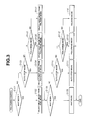
- Fig. 3 is a flow chart showing a following control procedure performed by a following controller in the control system of Fig. 1.
- Fig. 4 is a flow chart showing a procedure in a step S102 of Fig. 3, for selecting a next mode reached from a wait mode.
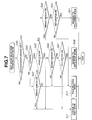
- Fig. 5 is a flow chart showing a procedure in a step S104 of Fig. 3, for selecting a next mode from an auto-stop mode.
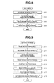
- Fig. 6 is a flow chart showing a procedure in a step S106 of Fig. 3, for selecting a next mode from a following mode.
- Fig. 7 is a flow chart showing a procedure in a step S107 of Fig. 3, for selecting a next mode from a release mode.
- Fig. 8 is a flow chart showing a wait mode procedure performed in the control system of Fig. 1.
- Fig. 9 is a flow chart showing an auto-stop mode procedure performed in the control system of Fig. 1.
- Fig. 10 is a flow chart showing a following mode procedure performed in the control system of Fig. 1.
- Fig. 11 is a flow chart showing a release mode procedure performed in the control system of Fig. 1.
- Fig. 12 is a flow chart showing another example of the procedure in the step S102 of Fig. 3, for selecting the next mode from the wait mode.
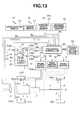
- Fig. 13 is a schematic view showing a preceding vehicle following control system according to a second embodiment of the present invention.
- Fig. 14 is a flow chart showing a wait mode procedure according to a second embodiment of the present invention.
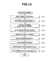
- Fig. 15 is an auto-stop mode procedure according to the second embodiment.
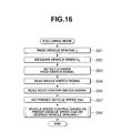
- Fig. 16 is a flow chart showing a following mode procedure according to the second embodiment.
- Fig. 1 shows a vehicle (controlled vehicle) equipped with a preceding vehicle following control system according to a first embodiment of the present invention.
- the controlled vehicle is a rear wheel drive vehicle having left and right front non-driving wheels 1FL and 1FR and left and right rear driving wheels 1RL and 1RR.
- a driving force of an engine 2 is transmitted through an automatic transmission 3, a propeller shaft 4, a final reduction assembly 5,and rear axle shafts 6 to the rear wheels 1RL and 1RR.
- a brake control unit 8 controls the brake oil pressure in each disc brake 7.
- the brake control unit 8 produces brake fluid pressure in response to depression of a brake pedal 16. Moreover, the brake control unit 8 produces the brake fluid pressure in response to a brake control signal representing a desired brake fluid pressure PB* supplied from a following controller 30.
- An engine output control unit 9 controls the output of the engine 2.
- One way to control the engine output is to control the engine speed (rpm) by regulating the opening (degree) TH of a throttle valve for the engine 2.
- Another way is to control an idle speed of the engine 2 by regulating the opening of an idle control valve.
- the engine output control unit 9 is arranged to regulate the throttle valve opening TH.
- a transmission control unit 10 controls a shift position of the automatic transmission. In response to an up/down shift control signal TS from the following controller 30, the transmission control unit 10 controls the shift position of the automatic transmission 3 in the upshift direction or downshift direction.
- a vehicle spacing sensor (or distance sensor) 12 is a device for sensing a vehicle spacing (or vehicle-to-vehicle distance or separation) from the controlled vehicle to a preceding vehicle ahead.
- the spacing sensor 12 is a radar type sensor disposed at a front lower portion of the vehicle body, and arranged to transmit laser light sweepingly and receive light reflected from a preceding vehicle.
- the spacing sensor 12 serves as means for sensing a vehicle spacing.
- Wheel speed sensors 13FL and 13FR are arranged to sense wheel speeds of the left and right front non-driving wheels 1FL and 1FR, respectively.
- the wheel speed sensors 13FL and 13FR are used as means for sensing a vehicle speed.
- An accelerator switch 15 is a device for sensing a driver's operation or intention of accelerating the controlled vehicle.
- the accelerator switch 15 is arranged to detect depression of an accelerator pedal 14 of the controlled vehicle.
- a brake switch 17 is a device for sensing a driver's operation or intention of braking the vehicle.
- the brake switch 17 is arranged to detect depression of a brake pedal 16.
- a brake pressure sensor 18 senses the brake pressure outputted from the brake control unit 8.
- the sensed brake pressure is used to detect a driver's operation or intention of increasing the braking force (in steps S24 and S34).
- a steering angle sensor 19 senses a steering angle 6 of a steering wheel 19a of the controlled vehicle.
- a main switch SW M is an input device for selecting execution or non-execution of the following control.
- the main switch SW M serves as start commanding means for producing a start command signal.
- a set switch SW S and a cancel switch SW C serving as cancel commanding means for producing a cancel command signal.
- a drive range detecting switch SW D is a device turning on when a drive range is selected with a select lever of the transmission 3.
- the main switch SW M of this example includes a momentary type selector switch 20, to be operated by a driver, and a self-holding type relay circuit 21.
- the selector switch 20 has one terminal connected through an ignition switch SW IG to a battery B.
- the selector switch 20 has an off position, a neutral position, and an on position.
- a first input terminal ti1 for receiving a switch signal S IG from the ignition switch SW IG is disconnected from an output terminal t0.
- a second input terminal ti2 for receiving power supply from the relay circuit 21 is connected with the output terminal t0.
- the first and second input terminals ti1 and ti2 are connected with the output terminal t0.
- the relay circuit 21 has a normally open contact s1 and a relay coil RL for driving the normally open contact s1.
- One end of the normally open contact sl is connected with the ignition switch SW IG .
- the other end of the normally open contact sl is connected to the following controller 30 directly on one hand and through the set switch SW S , as shown in Fig. 1.
- the other end of the normally open contact sl is further connected to the second input terminal ti2 of the selector switch 20.
- One end of the relay coil RL is connected with the output terminal t0 of the selector switch 20, and the other end of the relay coil RL is grounded.
- the following controller 30 collects input information by receiving sensor signals from the vehicle spacing sensor 12, the wheel speed sensors 13FL and 14FR, the accelerator switch 15, the brake switch 17, the brake pressure sensor 18, and the steering angle sensor 19, and further receiving switch signals S M , S SET , and S CAN from the main switch SW M , the set switch SW S , and the cancel switch SW C , and a switch signal S DR from the drive range detecting switch SW D .
- the following controller 30 changes over a control mode among a wait mode (control waiting mode) WM, an auto-stop mode SM, a following mode FM,and a release mode RM, as shown in Fig. 2.
- the auto-stop mode SM is a mode for holding the controlled vehicle in a stop or rest state by holding a braking force at a predetermined magnitude.
- the following mode FM is a mode for performing vehicle speed control to bring the actual speed Vs closer to a preset vehicle speed Vset when a preceding vehicle is not detected, and to bring the actual vehicle spacing L closer to a desired vehicle spacing L* when a preceding vehicle is detected, by controlling the brake control unit 8, the engine control unit 9, and the transmission control unit 10.
- the release mode RM is a mode for canceling the auto-stop mode SM or the following modeFM, but holding the braking force produced in the auto-stop mode or the following mode.
- the following controller 30 changes the control mode from a control off state to the wait mode WM.
- the control mode is changed from the wait mode to the auto-stop mode SM if, in the wait mode, a predetermined first transition (or wait-to-stop mode-change) condition is satisfied.
- the first transition condition is satisfied when,first,the automatic transmission 3 is in the drive range, second, the controlled vehicle is in the stop (or rest) state, and,third,the set switch SWs is in the on state.
- the control mode is changed to the following mode FM if, in the wait mode, a predetermined second (wait-to-follow) transition condition is satisfied.
- the second transition condition is satisfied when,first,the automatic transmission 3 is in the drive range, second,the brake switch 17 is in the off state, and,third,the set switch SW S is in the on state.
- the control mode is changed to the following mode FM if a predetermined third (stop-to-follow) transition condition is satisfied in the auto-stop mode SM.
- the third transition condition is satisfied when a preceding vehicle moves forward by a predetermined amount from the position of the preceding vehicle at the time of the start of the auto-stop mode SM.
- the control mode is changed to the auto-stop mode SM if a predetermined fourth (follow-to-stop) transition condition is satisfied in the following mode FM.
- the fourth transition condition is satisfied when,first,the sensed actual vehicle spacing L to a preceding vehicle is equal to or smaller than a predetermined spacing value, and, second, the sensed actual vehicle speed Vs of the controlled vehicle is equal to or lower than a predetermined speed value.
- the control mode is changed from the auto-stop mode SM to the release mode RM.
- the fifth transition condition is satisfied when any one or more of first, second, and third subordinate conditions is satisfied.
- the first subordinate condition is satisfied when the cancel switch SW C is turned off.
- the second subordinate condition is satisfied when the steering wheel angle ⁇ sensed by the steering angle sensor 19 becomes equal to or greater than a predetermined angle value.
- the third subordinate condition is satisfied when the automatic transmission 3 is shifted out of the drive rage to another range.
- the control mode is changed from the release mode RM to the auto-stop mode SM.
- the sixth transition condition is satisfied when, first,the controlled vehicle is in the stop state, second, the control range of the automatic transmission 3 is the drive range, and, third, the set switch SW S is in the on state.
- the following controller 30 effects a mode change from the following mode FM to the release mode RM.
- the seventh transition condition is satisfied when the driver performs any one or more of a depressing operation of the accelerator pedal 14 (accelerating operation), a depressing operation of the brake pedal 16 (braking operation) and a shift operation from the drive range to another range.
- the following controller 30 effects a mode change from the release mode RM to the following mode FM.
- the eighth transition condition is satisfied when first the controlled vehicle is in a running state in the release mode, second the automatic transmission 3 is in the drive range, and third the set switch SWs is in the on state.
- the following controller 30 effects a mode change from the release mode RM to the wait mode WM.
- the ninth transition condition is satisfied when the accelerator switch 15 or the brake switch 17 is in the on state.
- Fig. 3 shows a following control procedure performed, as a main program, by the following controller 30.
- the controller 30 examines whether the current control mode is the wait mode WM, or not. In the case of the wait mode WM, the controller 30 proceeds to a step S102, and performs, at the step S102, a next mode selection process for selecting a target mode to be reached by transition from the wait mode WM. After the step S102, the controller 30 proceeds to a step S108.
- the controller 30 proceeds to a step S103, and examines whether the current control mode is the auto-stop mode or not. If it is, the controller 30 proceeds to a step S104 to perform a next mode selection process for selecting a target mode to be reached by transition from the auto-stop mode SM. After the step S104, the controller 30 proceeds to the step S108.
- the controller 30 proceeds from the step S103 to a step S105, and examines whether the current control mode is the following mode FM or not. In the case of the following mode FM, the controller 30 proceeds to a step S106 and performs a next mode selection process for selecting a target mode to be reached by transition from the following mode FM at the step S106. Thereafter, the controller 30 proceeds to the step S108.
- the controller 30 proceeds from the step S105 to a step S107, and performs a next mode selection process for selecting a target mode to be reached by transition from the release mode RM at the step S107. Thereafter, the controller 30 proceeds to the step S108.
- the controller 30 determines whether the current control mode is the wait mode WM or not, like the step S101. In the case of the wait mode WM, the controller 30 performs a wait mode process at a step S109, and then terminates the following control process of Fig. 3. If it is not the wait mode WM, the controller 30 proceeds to a step S110.
- the controller 30 determines whether the current control mode is the auto-stop mode SM or not, like the step S103. In the case of the auto-stop mode SM, the controller 30 performs a auto-stop mode process at a step S111, and then terminates the following control process. If it is not the auto-stop mode SM, the controller 30 proceeds to a step S112.
- the controller 30 determines whether the current control mode is the following mode FM or not, like the step S105. In the case of the following mode FM, the controller 30 performs a following mode process at a step S113, and then terminates the following control process of Fig. 3. If it is not the following mode FM, the controller 30 performs a release mode process at a step S114, and terminate the following control process.
- Fig. 4 shows the next mode selecting process from the wait mode, of the step S102.
- the controller 30 examines whether the range of the automatic transmission 3 is the drive range or not. If the range of the automatic transmission 3 is other than the drive range, the controller 30 proceeds to a step S12 and holds the wait mode WM. Thereafter, the controller 30 terminates the process of Fig. 4. In the case of the drive range, the controller 30 proceeds to a step S13.
- the controller 30 examines whether the controlled vehicle is in the stop state by examining whether the vehicle speed Vs of the controlled vehicle is equal to "zero".
- the vehicle speed Vs is calculated from the wheel speeds V WFL and V WFR sensed by the front wheel speed sensors 13FL and 13FR, as mentioned later. If the controlled vehicle is in the stop state, the controller 30 proceeds to a step S14, and examines whether the brake switch 17 is in the on state or not. From the step S14, the controller 30 proceeds to the step S12 in the case of the brake switch 17 being in the off state, and proceeds to a step S15 in the case of the on state.
- the controller 30 examines whether the set switch SW S is in the on state or not. In the case of the off state of the set switch SW S , the controller 30 proceeds to the step S12. In the case of the on state of the set switch SW S , the controller 30 proceeds to a step S16. At the step S16, the controller 30 effects a (wait-to-stop) mode change from the wait mode WM to the auto-stop mode SM. Then, the controller 30 terminates the process of Fig. 4.
- the controller 30 When the controlled vehicle is in a running state, the controller 30 proceeds from the step S13 to a step S17 to examine whether the brake switch 17 is in the on state or not. From the step S17, the controller 30 proceeds to the step S12 in the case of the on state of the brake switch 17, and to a step S18 in the case of the off state of the brake switch 17. At the step S18, the controller 30 examines whether the set switch SW S is in the on state or not. The controller 30 proceeds to the step S12 in the case of the off state of the set switch SW S and to a step S19 in the case of the on state of the set switch SW S . The controller 30 changes the control mode to the following mode FM at the step S19, and thereafter terminates the process of Fig. 4.
- the step S11, S13 ⁇ S15 are decision steps for checking the first condition for mode change from the wait mode WM to the auto-stop mode SM.
- the steps S11, S13, S17, and S18 are designed to check the second condition for mode change from the wait mode WM to the following mode FM.
- Fig. 5 shows the next mode selecting process from the auto-stop mode, of the step S104.
- the controller 30 examines whether the cancel switch SW C is in the on state or not. If the cancel switch SWC is in the on state, the controller 30 proceeds to a step S22 and changes the control mode to the release mode RM. Thereafter, the controller 30 terminates the process of Fig. 5. If the cancel switch SW C is in the off state, the controller 30 proceeds to a step S21. At the step S21, the controller 30 examines whether the range of the automatic transmission 3 is shifted out of the drive range or not. If the range of the automatic transmission 3 is other than the drive range, the controller 30 proceeds to the step S22 to change the control mode to the release mode RM. In the case of the drive range being held unchanged, the controller 30 proceeds to a step S23.
- the controller 30 examines whether the steering angle ⁇ sensed by the steering angle sensor 19 is equal to or greater than a predetermined angle value ⁇ s. If ⁇ ⁇ ⁇ s, the controller 30 proceeds to the step S22. If ⁇ ⁇ ⁇ s, then the controller 30 proceeds to a step S24. At the step S24, the controller 30 determines whether the brake pedal 16 is depressed further, by examining whether a current brake pressure P B (n) sensed by the brake pressure sensor 18 is greater than a previous value P B (n-1) of the brake pressure obtained in the previous control cycle. From the step S24, the controller 30 proceeds to the step S22 if the brake pedal 16 is depressed further, and to a step S25 if it is not.
- the controller 30 determines whether a preceding vehicle has started, by examining whether the vehicle spacing L sensed by the vehicle spacing sensor 12 is increased by an amount equal to or greater than a predetermined value ⁇ L. If the increase of the actual vehicle spacing L is smaller than the predetermined value ⁇ L, the controller 30 presumes the preceding vehicle is still in the stop state, and proceeds to a step S26.
- the controller 30 examines whether the accelerator switch 15 is in the on state or not. From the step S26, the controller 30 proceeds to the step S22 in the case of the on state of the accelerator switch 15, and to a step S27 in the case of the off state of the accelerator switch 15. At the step S27, the controller 30 holds the auto-stop mode SM and terminates the process.
- the controller 30 presumes that the preceding vehicle has started, and proceeds from the step S25 to a step S28 to examine whether the accelerator switch 15 is in the on state or not. If the accelerator switch 15 is in the on state, the controller 30 proceeds from the step S28 to a step S29, and changes the control mode to the following mode at the step S29. Then, the controller 30 terminates the process of Fig. 5. If the accelerator switch 15 is in the off state, the controller 30 proceeds to a step S30 and examines whether the set switch SW S is in the on state or not. The controller 30 proceeds to the step S27 if the set switch SW S is in the off state, and to the step S29 if the set switch SW S is in the on state.
- the steps S20, S21, S23, S24, and S26 are a program section for checking the fifth condition for stop-to-release mode change from the auto-stop mode SM to the release mode RM.
- the steps S25, S28,and S30 are a section to check the third condition for stop-to-follow mode change from the auto-stop mode SM to the following mode FM.
- Fig. 6 shows the next mode selecting process from the following mode, of the step S106.
- the controller 30 examines whether the range of the automatic transmission 3 is shifted out of the drive range or not. If the range of the automatic transmission 3 is other than the drive range, the controller 30 proceeds to a step S32 and changes the control mode to the release mode RM. Thereafter, the controller 30 terminates the process of Fig. 6. In the case of the drive range being held unchanged, the controller 30 proceeds to a step S33.
- the controller 30 examines whether the accelerator switch 15 is in the on state or not. If the accelerator switch 15 is in the on state, the controller 30 proceeds to the step S32. If the accelerator switch 15 is not in the on state, then the controller 30 proceeds to a step S34. At the step S34, the controller 30 determines whether the brake pedal 16 is depressed further, by examining whether a current brake pressure P B (n) sensed by the brake pressure sensor 18 is greater than a previous value P B (n-1) of the brake pressure obtained in the previous control cycle. From the step S34, the controller 30 proceeds to the step S32 if the brake pedal 16 is depressed further, and to a step S35 if it is not.
- the controller 30 determines whether the vehicle spacing L sensed by the vehicle spacing sensor 12 is equal to or smaller than a predetermine spacing value L L . If L ⁇ L L , the controller 30 proceeds to a step S36. At the step S36, the controller 30 examines whether the actual vehicle speed V S of the controlled vehicle is equal to or lower than a predetermined speed value V L . If V S ⁇ V L , the controller 30 proceeds to the step S37, changes the control mode to the auto-stop mode SM at the step S37, and then terminates the process of Fig. 6. If L > L L , or if V S > VL, the controller 30 proceeds from the step S35 or the step S36 to a step S38, holds the following control mode FM unchanged, and then terminates the process of Fig. 6.
- the steps S31, S33, and S34 are a program section for checking the seventh condition for mode change from the following mode FM to the release mode RM.
- the steps S35 and S36 are a section to check the fourth condition for mode change from the following mode FM to the auto-stop mode SM.
- Fig. 7 shows the next mode selecting process from the release mode, of the step S107.
- the controller 30 examines at a step S40 whether the accelerator switch 15 is in the on state or not. If it is, the controller 30 proceeds to a step S41, changes the control mode to the wait mode WM at the step S41, and then terminates the process of Fig. 7. If the accelerator switch 15 is in the off state, the controller 30 proceeds to a step S42.
- the controller 30 examines whether the automatic transmission 3 is in the drive range or not. If the range of the automatic transmission 3 is not the drive range, the controller 30 proceeds to a step S43, and examines at the step S43 whether the brake switch 17 is in the on state or not. If the brake switch 17 is in the on state, the controller 30 proceeds to the step S41. If the brake switch 17 is in the off state, the controller 30 proceeds to a step S44, holds the release mode unchanged and then terminates the process of Fig. 7. In the case of the drive range, the controller 30 proceeds from the step S42 to a step S45.
- the controller 30 determines whether the controlled vehicle is in the stop state or not. If the controlled vehicle is in the stop state, the controller 30 proceeds to a step S46, and examines at the step S46 whether the brake switch 17 is in the on state or not. In the case of the brake switch 17 being in the off state, the controller 30 proceeds to the step S44. In the case of the on state, the controller 30 proceeds to a step S47, and examines at the step S47 whether the set switch SW S is in the on state or not. If the set switch SW S is in the off state, the controller 30 proceeds to the step S41. If the set switch SW S is in the on state, the controller 30 proceeds to a step S48, changes the control mode to the auto-stop mode SM at the step S48, and then terminates the process.
- the controller 30 proceeds from the step S45 to a step S49, and examines at the step S49 whether the brake switch 17 is in the on state or not. If it is, the controller 30 proceeds to the step S41. If the brake switch 17 is in the off state, the controller 30 proceeds to a step S50, and examines at the step S50 whether the set switch SW S is in the on state or not. If it is in the off state, the controller 30 proceeds to the step S44. If the set switch SW S is in the on state, the controller 30 proceeds from the step S50 to a step S51, changes the control mode to the following mode FM, and terminates the process.
- the steps S40, S43, S47, and S49 are steps for checking the ninth condition from the release mode to the wait mode.
- the steps S40, S42, S45, S46, and S47 are steps for checking the sixth condition from the release mode to the auto-stop mode.
- the steps S40, S42, S45, S49, and S50 are steps for checking the eighth condition from the release mode to the following mode.
- Fig. 8 shows a wait mode process of the step S109.
- the controller 30 calculates the actual vehicle speed V S .
- the controller 30 measures the number of pulses per unit time or the time interval between pulses in each of the sensor signals from the wheel speed sensors 13FL and 13FR, and calculates the front wheel speeds V FL and V FR from the thus-measured quantity and the tire outside diameter. Then, the vehicle speed V S is set equal to an average of the wheel speeds V FL and V FR .
- the controller 30 reads the switch signal of the drive range detecting switch SW D provided at the drive range position of the select lever for the automatic transmission 3. Then, the controller 30 reads the switch signal of the brake switch 17 at a step S63, further reads the switch signal of the set switch SW S at a step S64, and terminates the process.
- Fig. 9 shows the auto-stop mode process of the step S111 shown in Fig. 3.
- the controller 30 first reads the vehicle spacing L sensed by the vehicle spacing sensor 12 at a step S71, measures, at a step S72, the vehicle speed Vs in the same manner as in the step S61 of Fig. 8, further reads the switch signal of the drive range detecting switch SW D at a step S73, reads the switch signal of the brake switch 17 at a step S74, reads the switch signal of the set switch SW S at a step S75, reads the steering angle ⁇ sensed by the steering angle sensor 19 at a step S76, and reads a winker signal at a step S77.
- the controller 30 reads the brake pressure P B sensed by the brake pressure sensor 18, sets a desired brake pressure P B * equal to the thus-obtained value of the brake pressure P B , and delivers the desired brake pressure P B * to the brake control unit 8.
- Fig. 10 shows the following mode process of the step S113 of Fig. 3.
- the controller 30 first reads the vehicle spacing L sensed by the vehicle spacing sensor 12 at a step S81, measures, at a step S82, the vehicle speed Vs in the same manner as in the step S61 of Fig. 8, further reads the switch signal of the drive range detecting switch SW D at a step S83, reads the switch signal of the brake switch 17 at a step S84, and reads the switch signal of the accelerator switch 15 at a step S85.
- the controller 30 calculates a desired vehicle spacing L* from the vehicle speed Vs according to an equation (1) below, calculates a desired vehicle speed V* in accordance with a deviation between the desired vehicle spacing L* and the actual vehicle spacing L, and controls the vehicle speed in accordance with the desired vehicle speed V* by controlling the brake control unit 8, the engine output control unit 9, and the transmission control unit 10.
- L* V S ⁇ T CF + T OF
- T CF is a time (or time gap) required for the controlled vehicle to reach a position at a distance L0 [m] from a current position of a preceding vehicle in the rear of the preceding vehicle
- T OF is a predetermined offset time.
- the controller 30 selects a smaller one of the desired vehicle speed V* and the preset vehicle speed Vset set by the driver, as a controlled vehicle speed Vc, calculates a command driving force F OR to bring the actual vehicle speed Vs closer to the controlled vehicle speed Vc, and an estimated disturbance dv' by using an ordinary feedback control system and a vehicle speed servo system based on a robust model matching control technique including a model matching compensator and a robust compensator as disclosed in United States Patent No.
- 5 959 572 calculates a desired driving/braking force F* by determining a difference between F OR and dv', and controls the vehicle speed by controlling the brake control unit 8, the engine output control unit 9, and the transmission control unit 10 in accordance with the desired driving/braking force F*.
- the contents of this U.S. Patent No. 5 959 572 are herein incorporated by reference.
- Fig. 11 shows the release mode process of the step S114 shown in Fig. 3.
- the following controller 30 first measures the vehicle speed Vs at a step S91, reads the switch signal of the drive range detecting switch SW D at a step S92, reads the switch signal of the brake switch 17 at a step S93, reads the switch signal of the accelerator switch 15 at a step S94, and reads the switch signal of the set switch SW S at a step S95. Then, at a step S96, the controller 30 holds the desired brake pressure P B * determined in the auto-stop mode SM or the following mode FM. Alternatively, the controller 30 decreases this desired brake pressure P B * by an amount ⁇ P each time, and thereby gradually decreases the brake pressure by delivering the gradually decreasing desired brake pressure P B * to the brake control unit 8.
- the following control process of Fig. 3 serves as following controlling means.
- the step S61 of Fig. 8, the step S72 of Fig. 9, the step S82 of Fig. 10, the step S91 of Fig. 11, and the wheel speed sensors 13FL and 13FR serve as vehicle speed sensing means.
- the select lever is in the position for the parking range, the parking brake is applied, and the controlled vehicle and a preceding vehicle are both in the stop state, then the following controller 30 is in the off state disconnected from the power supply, and the control system is in the control off state.
- the control system sets the control mode to the wait mode WM, and reads the input information from the switches and sensors.
- the following control process of Fig. 3 is not yet operative.
- the relay circuit 21 is turned on into the self holding state, and holds the switch signal S M in the on state even if the selector switch 20 is returned to the neutral position.
- the following controller 30 starts executing the following control process of Fig. 3. Since the control mode is initially set to the wait mode WM, the following controller 30 proceeds from the step S101 to the step S102, and performs the mode selection from the wait mode shown in Fig. 4. The automatic transmission 3 is still in the parking range. Accordingly the following controller 30 proceeds from the step S11 to the step S12 of Fig. 4, and maintains the wait mode WM.
- the following controller 30 proceeds from the step S108 of Fig. 3 to the step S109 to perform the wait mode control process of Fig. 8.
- the controller 30 proceeds from the step S11 of Fig. 4 through the steps S13 and S14 to the step S15.
- the set switch SW S is in the off state, and accordingly the following controller 30 maintains the wait mode WM by proceeding to the step S12.
- the following controller 30 proceeds from the step S15 to the step S16, and changes the control mode from the wait mode WM to the auto-stop mode SM.
- the following controller 30 reads the actual vehicle spacing L, measures the actual vehicle speed V S , and reads the various input information.
- the desired brake pressure P B * is set equal to the actual brake pressure P B sensed by the brake pressure sensor 18, and supplied to the brake control unit 8.
- the following controller 30 proceeds through the steps S20 ⁇ S25 to the step S26, confirms that the accelerator switch 15 is in the off state at the S26, and maintains the auto-stop mode by proceeding to the step S27.
- the controller 30 proceeds from the step S24 to the step S22, and changes the control mode to the release mode RM.
- the accelerator switch 15 is in the off state
- the drive range detecting switch SW D is in the on state
- the controlled vehicle is in the stop state
- the brake switch 17 is in the on state. Therefore, in the release mode RM, the following controller 30 proceeds through the steps S40, S42, S45, and S46, to the step S47, and returns to the auto-stop mode SM if the set switch SW S is turned on again.
- the following controller 30 proceeds from the step S25 in Fig. 5 to the step S28. Therefore, when the driver depresses the accelerator pedal 14 or turns on the set switch SW S , the control mode is changed to the following mode FM pursuant to the driver's intention.
- the control system calculates the desired acceleration/deceleration so as to bring the actual vehicle spacing to a preceding vehicle sensed by the vehicle spacing sensor 12, closer to the desired vehicle spacing L*, makes the desired driving/braking force F* positive in accordance with the desired acceleration/deceleration, and delivers the command throttle opening TH to the engine output control unit 9. As a result, the controlled vehicle is started and accelerated.
- the control system reduces the command throttle opening TH to zero to fully close the throttle valve, produces the shift position signal TS, according to need, to command the transmission control unit 10 to effect downshift to increase the engine braking force, and produces the desired brake pressure P B * corresponding to the desired driving/braking force F*, to the brake control unit 8, so that the controlled vehicle is put in the braking state to decrease the actual vehicle spacing L toward the desired spacing L*.
- the shift position signal TS is delivered to the transmission control unit 10 to effect an upshift, and the desired brake pressure P B * is decreased.
- the throttle opening command TH is delivered to the engine output control unit 9, and the control system returns to the driving force control state.
- the control system controls the vehicle speed so as to bring the actual vehicle speed Vs closer to the preset vehicle speed Vset set by the driver.
- the control system decreases the vehicle speed of the controlled vehicle to zero so as to maintain the desired vehicle spacing L* by outputting the desired brake pressure P B *.
- the desired spacing L* is decreased as the vehicle speed V S decreases.
- control system If, thereafter, the preceding vehicle starts, the control system returns the control mode to the following mode, as mentioned before, in response to a driver's operation to turn on the accelerator switch 15 by depression of the accelerator pedal, or a driver's operation to turn on the set switch SW S again.
- the switch signal S D of the drive range detecting switch SW D turns off, and hence the control system changes the control mode to the release mode RM by following the course from the step S31 to the step S32. If the desired brake pressure P B * is produced in the following mode immediately before the mode change from the following mode to the release mode, the control system holds the desired brake pressure P B * at the magnitude immediately before the mode change or decrease the desired brake pressure P B * gradually.
- the brake switch 17 turns on by depression of the brake pedal 16
- the control system returns the control mode to the wait mode WM by following the course from the step S43 to the step S41.
- control mode is changed from the following mode FM to the release mode if the accelerator switch 15 turns on by depression of the accelerator pedal 14 or if the brake pedal 16 is depressed further.
- the control system returns the control mode to the wait mode if the accelerator switch 15 turns on by depression of the accelerator pedal 14, if the accelerator switch 17 is off, but the brake switch 17 turns on by depression of the brake pedal 16 in the running state with the transmission in the drive range, or if the controlled vehicle stops and the set switch SW S is off. If, however, in the running state in the drive range, the brake switch 17 is off and the set switch SW S is off, then the control system holds the release mode RM. The control mode is changed to the following mode FM if the set switch SW S is turned on in the running state in the drive range, and to the auto-stop mode SM if the controlled vehicle stops in the drive range and the set switch SW S is turned on.
- the control system changes the control mode from the wait mode to the following mode as in the conventional system. If the main switch SW M is turned off or the ignition switch SW IG is turned off, then the control system terminates the following control process of Fig. 3 and turns in the control off state.
- the control system is set to the wait mode WM by turn-on of the main switch SWM.
- the driver can change the control mode to the auto-stop mode or the following mode by turning on the set switch SW S in the drive range, and by so doing, starts the following control at a desired timing.
- the control system holds the brake pressure, if any, in the previous mode, and thereby prevents unnatural feeling by preventing abrupt change in the brake pressure.
- Fig. 12 shows another practical example according to the first embodiment of the present invention.
- the step S15 shown in Fig. 4 is omitted in the mode selection from the wait mode WM, so that the first condition for mode change from the wait mode to the auto-stop mode SM does not include a condition about the set switch SW S .
- the brake switch 17 if the brake switch 17 is in the on state, the following controller 30 proceeds directly from the step S14 to the step S16 and effects a mode change to the auto-stop mode SM.
- the next mode selection process in the example shown in Fig. 7 is designed to check the on state of the accelerator switch 15 or the brake switch 17.
- the control system it is optional to arrange the control system so that the following controller 30 decreases the desired brake pressure P B * gradually ⁇ P by ⁇ P at the step S96 in the release mode process of Fig. 11, and then effects a mode change from the release mode RM to the wait mode WM when the desired brake pressure PB* becomes equal to or lower than a predetermined pressure value.
- step S96 in the release mode process of Fig. 11 it is optional to vary the rate of decrease of the desired brake pressure P B * in accordance with the vehicle spacing and/or the vehicle speed.
- the control system decreases the desired brake pressure P B * more gradually in the presence of a preceding vehicle than in the absence of a preceding vehicle, by making the decrease quantity ⁇ P smaller when a preceding vehicle is detected.
- the control system decreases the desired brake pressure PB* more gradually by decreasing ⁇ P when the vehicle spacing to a preceding vehicle becomes smaller.
- the control system makes smaller the decrease quantity ⁇ P with decrease in the vehicle speed, and thereby causes the desired brake pressure P B * to decrease more gradually in a lower vehicle speed region than in a higher vehicle speed region.
- the 7th condition for mode change from the following mode to the release mode does not include a condition about the cancel switch SW C .
- the wheel speed sensors 13FL and 13FR are used as a vehicle speed sensor.
- the vehicle speed sensor may be arranged to sense rotation of the output shaft of the automatic transmission 3. It is further optional to use, as the vehicle speed, a vehicle body speed estimated from wheel speeds by an anti-skid brake control system (or by a means for estimating vehicle body speed).
- the desired spacing L* is calculated in accordance with the actual vehicle speed V S .
- the control system may be arranged to calculate the desired spacing L* by determining a relative speed ⁇ V by differentiating the actual vehicle speed L with a band pass filtering operation or a high-pass filtering operation, to calculates a preceding target speed Vt of a preceding vehicle by adding the relative speed ⁇ V to the actual vehicle speed V S , and to calculate the desired spacing L* in accordance with the target speed Vt.
- the present invention is not limited to the laser radar sensor.
- the vehicle spacing sensor 12 may be a sensor utilizing a millimetre wave radar, or may be an image processing system arranged to calculate the vehicle spacing by processing images produced by a stereo camera.
- Figs. 13 ⁇ 16 show a second embodiment of the present invention.
- Fig. 13 shows a vehicle following control system according to the second embodiment.
- This control system includes a vehicle speed setting device 50 for setting and adjusting the preset vehicle speed Vset, in addition to the components shown in Fig. 1.
- the driver can set and change the preset vehicle speed Vset with the input device 50 in predetermined control modes.
- a step for adjusting the preset vehicle speed Vset is added in each of Figs. 13 ⁇ 15.
- the wait mode control process of Fig. 13 is different from Fig. 8 in the addition of a set speed adjusting step 65 after the step S64.
- the auto-stop mode control process of Fig. 14 is different from Fig. 9 in the addition of a set speed adjusting step S79 between the steps S77 and S78.
- the following mode control process of Fig. 15 is different from Fig. 10 in the addition of a set speed adjusting step S87 between the steps S85 and S86.
- the control system may be arranged to enable the driver to adjust the preset vehicle speed by turning on a switch such as a resume switch to set the current vehicle speed V S as the preset vehicle speed Vset, or by varying the preset vehicle speed Vset by turning on an adjusting or setting switch and performing a count-up or count-down operation. If the controlled vehicle is in the stop state, the driver can adjust the preset speed by count-up or count-down operation in the on state of an adjusting or setting switch. Moreover, a ten-key pad can be used for inputting the preset vehicle speed Vset.
- the control system can use an adjusting or setting switch for adjusting the preset vehicle speed Vset by count-up or count-down, or a ten-key pad for adjusting the preset speed Vset.
- the driver can perform the preset speed adjusting operation in each of the wait mode, the auto-stop mode, and the following mode. Specifically in the wait mode and the auto-stop mode, the driver can adjust the preset speed Vset securely without error or influence on the driving operation in the stop state of the vehicle.
- the control system can perform the vehicle speed control by calculating the desired vehicle speed V* in accordance with the deviation of the actual vehicle spacing L from the desired spacing L* and controlling the vehicle speed so as to reduce the deviation of the actual vehicle speed V S from the desired vehicle speed V*, or in some other appropriate way.
- the control system may be arranged to calculate the desired acceleration/deceleration in accordance with the deviation of the actual spacing L from the desired spacing L* and to control the brake control unit 8, the engine output control unit 9, and the transmission control unit 10 in accordance with the desired acceleration/deceleration.
- the vehicle shown in Fig. 1 has the disc brakes 7.
- the present invention is not limited to the disc brake system.
- the control system may be arranged to control the regenerative braking force.
- the control system can perform the braking force electrically.
- the present invention can employ any brake system capable of controlling a braking force.
- the automatic transmission 3 is on the output side of the engine 2.
- the present invention is not limited to this arrangement.
- the present invention is applicable to a vehicle having a continuously variable transmission.
- the present invention is applicable not only to a rear wheel drive vehicle, but to a front wheel drive vehicle or a four wheel drive vehicle. Furthermore, the present invention is applicable to an electric vehicle having an electric motor instead of the engine 2 and a hybrid vehicle having an electric motor in addition to the engine 2. In this case, the control unit 10 may be arranged to control the electric motor.
- the steps S61 ⁇ S64, S71-S77, S81 ⁇ S85, S91 ⁇ S95 correspond to collecting means for collecting input information on vehicle operating conditions of the controlled vehicle.
- the step S78, S86, and S96 correspond to means for controlling at least one of driving force and braking force.
- the steps S16, S19, S22, S29, S32, S37, S41, S48, and S51 correspond to means for changing the control mode among the four modes shown in Fig. 2.
- the steps S22 and S32 correspond to releasing means for changing the control mode from one of the auto-stop mode and the following mode to the release mode.
- the step S41 corresponds to returning means for returning the control mode to the wait mode from the release mode.
- the decision steps S11, S13 ⁇ S15, S17, S18, S20 ⁇ S26, S28, S30, S31, S33 ⁇ S36, S40, S42, S43, S45 ⁇ S47, S49, and S50 correspond to discriminating means for producing condition signals for effecting mode changes.
Landscapes
- Engineering & Computer Science (AREA)
- Chemical & Material Sciences (AREA)
- Combustion & Propulsion (AREA)
- Transportation (AREA)
- Mechanical Engineering (AREA)
- Control Of Driving Devices And Active Controlling Of Vehicle (AREA)
- Controls For Constant Speed Travelling (AREA)
- Control Of Vehicle Engines Or Engines For Specific Uses (AREA)
- Traffic Control Systems (AREA)
- Hybrid Electric Vehicles (AREA)
- Auxiliary Drives, Propulsion Controls, And Safety Devices (AREA)
- Regulating Braking Force (AREA)
Applications Claiming Priority (2)
| Application Number | Priority Date | Filing Date | Title |
|---|---|---|---|
| JP18649799 | 1999-06-30 | ||
| JP18649799A JP3627575B2 (ja) | 1999-06-30 | 1999-06-30 | 車両用追従制御装置 |
Publications (3)
| Publication Number | Publication Date |
|---|---|
| EP1065090A2 true EP1065090A2 (fr) | 2001-01-03 |
| EP1065090A3 EP1065090A3 (fr) | 2002-02-06 |
| EP1065090B1 EP1065090B1 (fr) | 2006-08-30 |
Family
ID=16189533
Family Applications (1)
| Application Number | Title | Priority Date | Filing Date |
|---|---|---|---|
| EP00305547A Expired - Lifetime EP1065090B1 (fr) | 1999-06-30 | 2000-06-30 | Régulateur de vitesse avec régulation de la distance entre deux véhicules et du couple d'entrainement |
Country Status (4)
| Country | Link |
|---|---|
| US (1) | US6330508B1 (fr) |
| EP (1) | EP1065090B1 (fr) |
| JP (1) | JP3627575B2 (fr) |
| DE (1) | DE60030357T2 (fr) |
Cited By (13)
| Publication number | Priority date | Publication date | Assignee | Title |
|---|---|---|---|---|
| WO2001040011A1 (fr) * | 1999-12-04 | 2001-06-07 | Robert Bosch Gmbh | Regulateur de vitesse pour un vehicule automobile |
| EP1245427A2 (fr) * | 2001-03-19 | 2002-10-02 | Nissan Motor Company, Limited | Commande de vitesse avec affichage du mode de fonctionnement pour véhicule |
| DE10151717A1 (de) * | 2001-10-19 | 2003-04-30 | Bayerische Motoren Werke Ag | Geschwindigkeitsregel-System mit Abstandssensorik für ein Kraftfahrzeug |
| EP1344672A1 (fr) * | 2002-03-11 | 2003-09-17 | Hitachi, Ltd. | Système de régulation des espacements |
| EP1437254A1 (fr) * | 2003-01-09 | 2004-07-14 | Ford Global Technologies, Inc. | Régulateur de vitesse avec régulation de la distance entre deux véhicules |
| EP1442915A2 (fr) * | 2003-01-30 | 2004-08-04 | Robert Bosch Gmbh | Régulateur de vitesse avec plusieurs modes de fonctionnement |
| EP1442917A2 (fr) * | 2003-01-16 | 2004-08-04 | Ford Global Technologies, LLC | Régulations de vitesse adaptatives |
| EP1724174A3 (fr) * | 2005-05-20 | 2007-04-04 | Nissan Motor Company Limited | Système de commande de vitesses adaptatif |
| EP2052935A1 (fr) * | 2007-10-23 | 2009-04-29 | Nissan Motor Co., Ltd. | Système et procédé de support de maintien de la distance d'espacement |
| CN104442821A (zh) * | 2013-09-24 | 2015-03-25 | 福特全球技术公司 | 从自主车辆控制到响应驾驶员的控制的转换 |
| GB2523203A (en) * | 2014-02-18 | 2015-08-19 | Jaguar Land Rover Ltd | Control System and method |
| DE102005059967B4 (de) * | 2005-07-15 | 2016-05-04 | Mitsubishi Denki K.K. | Fahrsteuerungsvorrichtung für Fahrzeuge |
| FR3066984A1 (fr) * | 2017-06-06 | 2018-12-07 | Peugeot Citroen Automobiles Sa | Dispositif d’assistance a la conduite d’un vehicule par controle du freinage dans les phases d’arret |
Families Citing this family (23)
| Publication number | Priority date | Publication date | Assignee | Title |
|---|---|---|---|---|
| JP3912992B2 (ja) * | 2001-03-16 | 2007-05-09 | ダイハツ工業株式会社 | 追従走行装置及びその制御方法 |
| US7482916B2 (en) | 2004-03-15 | 2009-01-27 | Anita Au | Automatic signaling systems for vehicles |
| JP2006290328A (ja) | 2005-03-16 | 2006-10-26 | Nissan Motor Co Ltd | 先行車追従制御装置 |
| JP2006309650A (ja) * | 2005-05-02 | 2006-11-09 | Calsonic Kansei Corp | ナンバー認識装置及方法 |
| JP2006348830A (ja) * | 2005-06-15 | 2006-12-28 | Toyota Motor Corp | 走行制御装置 |
| US7937075B2 (en) | 2006-10-06 | 2011-05-03 | At&T Intellectual Property I, L.P. | Mode changing of a mobile communications device and vehicle settings when the mobile communications device is in proximity to a vehicle |
| GB2455584A (en) * | 2007-12-15 | 2009-06-17 | Anatolijs Fjodorovics | Distance based traffic control system for a vehicle |
| JP5237181B2 (ja) * | 2009-04-22 | 2013-07-17 | 本田技研工業株式会社 | 車両用走行制御装置 |
| JP4959758B2 (ja) * | 2009-08-11 | 2012-06-27 | 本田技研工業株式会社 | 走行制御装置 |
| IT1396698B1 (it) * | 2009-11-11 | 2012-12-14 | Nilfisk Advance Spa | Veicolo perfezionato per il trattamento e la pulizia di pavimenti e suoli |
| US8825345B2 (en) | 2010-07-16 | 2014-09-02 | Honda Motor Co., Ltd. | Engine control for a motor vehicle |
| JP5716844B2 (ja) * | 2011-12-22 | 2015-05-13 | トヨタ自動車株式会社 | アイドリングストップ制御装置、車両、および、車両制御方法 |
| JP2014000882A (ja) * | 2012-06-18 | 2014-01-09 | Toyota Motor Corp | 車両用走行制御装置 |
| GB2508668A (en) | 2012-12-10 | 2014-06-11 | Jaguar Land Rover Ltd | Adaptive cruise control (ACC) means for a host vehicle having regenerative and non-regenerative braking means |
| JP5867433B2 (ja) * | 2013-03-25 | 2016-02-24 | トヨタ自動車株式会社 | 車両の制御装置 |
| JP5999074B2 (ja) * | 2013-11-25 | 2016-09-28 | トヨタ自動車株式会社 | 車両用制御装置、エンジン制御方法 |
| KR102383331B1 (ko) * | 2016-11-22 | 2022-04-05 | 현대자동차주식회사 | 자동차의 avh 해제 방법 |
| DE102016014380A1 (de) * | 2016-12-02 | 2018-06-07 | Lucas Automotive Gmbh | Überwachung eines Anfahrvorgangs mit Geschwindigkeitsregelsystem |
| JP6819483B2 (ja) * | 2017-06-26 | 2021-01-27 | トヨタ自動車株式会社 | 車両の制御装置 |
| US10757485B2 (en) | 2017-08-25 | 2020-08-25 | Honda Motor Co., Ltd. | System and method for synchronized vehicle sensor data acquisition processing using vehicular communication |
| JP6978377B2 (ja) * | 2018-05-10 | 2021-12-08 | 本田技研工業株式会社 | 車両制御装置、及び車両制御装置を備える車両 |
| US11163317B2 (en) | 2018-07-31 | 2021-11-02 | Honda Motor Co., Ltd. | System and method for shared autonomy through cooperative sensing |
| US11181929B2 (en) | 2018-07-31 | 2021-11-23 | Honda Motor Co., Ltd. | System and method for shared autonomy through cooperative sensing |
Citations (4)
| Publication number | Priority date | Publication date | Assignee | Title |
|---|---|---|---|---|
| JPH0747862A (ja) | 1993-08-05 | 1995-02-21 | Mitsubishi Motors Corp | 自動車の走行制御装置 |
| JPH10272963A (ja) | 1997-03-31 | 1998-10-13 | Nissan Motor Co Ltd | 先行車追従制御装置 |
| JPH11186497A (ja) | 1997-12-17 | 1999-07-09 | Toshiba Corp | 半導体集積回路装置 |
| US5959572A (en) | 1997-03-31 | 1999-09-28 | Nissan Motor Co., Ltd. | Vehicle follow-up control apparatus |
Family Cites Families (5)
| Publication number | Priority date | Publication date | Assignee | Title |
|---|---|---|---|---|
| KR940001633B1 (ko) * | 1990-01-17 | 1994-02-28 | 미쯔비시 덴끼 가부시끼가이샤 | 주행 제어장치 |
| JP2987778B2 (ja) * | 1990-11-30 | 1999-12-06 | アイシン精機株式会社 | 車両速度制御装置 |
| US5805103A (en) * | 1995-09-27 | 1998-09-08 | Mazda Motor Corporation | Method of and system for monitoring preceding vehicles |
| US6223117B1 (en) * | 1997-05-27 | 2001-04-24 | General Motors Corporation | Cut-in management for an adaptive cruise control system |
| JP2001010373A (ja) * | 1999-07-01 | 2001-01-16 | Hitachi Ltd | 自動車の走行制御装置 |
-
1999
- 1999-06-30 JP JP18649799A patent/JP3627575B2/ja not_active Expired - Fee Related
-
2000
- 2000-06-30 US US09/609,242 patent/US6330508B1/en not_active Expired - Lifetime
- 2000-06-30 EP EP00305547A patent/EP1065090B1/fr not_active Expired - Lifetime
- 2000-06-30 DE DE60030357T patent/DE60030357T2/de not_active Expired - Lifetime
Patent Citations (4)
| Publication number | Priority date | Publication date | Assignee | Title |
|---|---|---|---|---|
| JPH0747862A (ja) | 1993-08-05 | 1995-02-21 | Mitsubishi Motors Corp | 自動車の走行制御装置 |
| JPH10272963A (ja) | 1997-03-31 | 1998-10-13 | Nissan Motor Co Ltd | 先行車追従制御装置 |
| US5959572A (en) | 1997-03-31 | 1999-09-28 | Nissan Motor Co., Ltd. | Vehicle follow-up control apparatus |
| JPH11186497A (ja) | 1997-12-17 | 1999-07-09 | Toshiba Corp | 半導体集積回路装置 |
Cited By (27)
| Publication number | Priority date | Publication date | Assignee | Title |
|---|---|---|---|---|
| WO2001040011A1 (fr) * | 1999-12-04 | 2001-06-07 | Robert Bosch Gmbh | Regulateur de vitesse pour un vehicule automobile |
| US6820709B1 (en) | 1999-12-04 | 2004-11-23 | Robert Bosch Gmbh | Speed controller for a motor vehicle |
| EP1245427A2 (fr) * | 2001-03-19 | 2002-10-02 | Nissan Motor Company, Limited | Commande de vitesse avec affichage du mode de fonctionnement pour véhicule |
| EP1245427A3 (fr) * | 2001-03-19 | 2004-11-17 | Nissan Motor Company, Limited | Commande de vitesse avec affichage du mode de fonctionnement pour véhicule |
| DE10151717A1 (de) * | 2001-10-19 | 2003-04-30 | Bayerische Motoren Werke Ag | Geschwindigkeitsregel-System mit Abstandssensorik für ein Kraftfahrzeug |
| EP1609657A3 (fr) * | 2001-10-19 | 2006-01-04 | Bayerische Motoren Werke Aktiengesellschaft | Régulateur de vitesse avec détection d'intervalle pour véhicule à moteur |
| EP1609657A2 (fr) * | 2001-10-19 | 2005-12-28 | Bayerische Motoren Werke Aktiengesellschaft | Régulateur de vitesse avec détection d'intervalle pour véhicule à moteur |
| EP1344672A1 (fr) * | 2002-03-11 | 2003-09-17 | Hitachi, Ltd. | Système de régulation des espacements |
| US6876915B2 (en) | 2002-03-11 | 2005-04-05 | Hitachi, Ltd. | Headway control system |
| EP1568532A2 (fr) * | 2002-03-11 | 2005-08-31 | Hitachi, Ltd. | Système de régulation des espacements |
| EP1568532A3 (fr) * | 2002-03-11 | 2005-09-07 | Hitachi, Ltd. | Système de régulation des espacements |
| EP1437254A1 (fr) * | 2003-01-09 | 2004-07-14 | Ford Global Technologies, Inc. | Régulateur de vitesse avec régulation de la distance entre deux véhicules |
| EP1442917A3 (fr) * | 2003-01-16 | 2005-10-19 | Ford Global Technologies, LLC | Régulations de vitesse adaptatives |
| EP1442917A2 (fr) * | 2003-01-16 | 2004-08-04 | Ford Global Technologies, LLC | Régulations de vitesse adaptatives |
| US7706954B2 (en) | 2003-01-30 | 2010-04-27 | Robert Bosch Gmbh | Speed controller having several operating modes |
| EP1442915A3 (fr) * | 2003-01-30 | 2007-08-15 | Robert Bosch Gmbh | Régulateur de vitesse avec plusieurs modes de fonctionnement |
| EP1442915A2 (fr) * | 2003-01-30 | 2004-08-04 | Robert Bosch Gmbh | Régulateur de vitesse avec plusieurs modes de fonctionnement |
| EP1724174A3 (fr) * | 2005-05-20 | 2007-04-04 | Nissan Motor Company Limited | Système de commande de vitesses adaptatif |
| US7664589B2 (en) | 2005-05-20 | 2010-02-16 | Nissan Motor Co., Ltd. | Apparatus and method for following a preceding vehicle |
| DE102005059967B4 (de) * | 2005-07-15 | 2016-05-04 | Mitsubishi Denki K.K. | Fahrsteuerungsvorrichtung für Fahrzeuge |
| EP2052935A1 (fr) * | 2007-10-23 | 2009-04-29 | Nissan Motor Co., Ltd. | Système et procédé de support de maintien de la distance d'espacement |
| CN104442821A (zh) * | 2013-09-24 | 2015-03-25 | 福特全球技术公司 | 从自主车辆控制到响应驾驶员的控制的转换 |
| CN104442821B (zh) * | 2013-09-24 | 2019-04-19 | 福特全球技术公司 | 从自主车辆控制到响应驾驶员的控制的转换 |
| GB2523203A (en) * | 2014-02-18 | 2015-08-19 | Jaguar Land Rover Ltd | Control System and method |
| GB2523203B (en) * | 2014-02-18 | 2017-01-11 | Jaguar Land Rover Ltd | Control System and method |
| US10106158B2 (en) | 2014-02-18 | 2018-10-23 | Jaguar Land Rover Limited | Control system and method |
| FR3066984A1 (fr) * | 2017-06-06 | 2018-12-07 | Peugeot Citroen Automobiles Sa | Dispositif d’assistance a la conduite d’un vehicule par controle du freinage dans les phases d’arret |
Also Published As
| Publication number | Publication date |
|---|---|
| DE60030357T2 (de) | 2007-08-30 |
| EP1065090B1 (fr) | 2006-08-30 |
| JP2001010371A (ja) | 2001-01-16 |
| JP3627575B2 (ja) | 2005-03-09 |
| US6330508B1 (en) | 2001-12-11 |
| EP1065090A3 (fr) | 2002-02-06 |
| DE60030357D1 (de) | 2006-10-12 |
Similar Documents
| Publication | Publication Date | Title |
|---|---|---|
| EP1065090B1 (fr) | Régulateur de vitesse avec régulation de la distance entre deux véhicules et du couple d'entrainement | |
| EP1065088B1 (fr) | Régulateur de vitesse pour véhicule | |
| US4969103A (en) | Speed control apparatus for an automotive vehicle with creep control | |
| EP1070624B1 (fr) | Dispositif de suivi d'un véhicule qui le précède | |
| US6658344B2 (en) | Vehicle traveling control system with state display apparatus | |
| JP3627582B2 (ja) | 車両用追従制御装置 | |
| JP3551756B2 (ja) | 車両用走行制御装置 | |
| US6926638B1 (en) | Method for carrying out an automated clutch actuation during non-driven operational phases | |
| EP0864781B1 (fr) | Dispositif et méthode de commande de changement de vitesse pour une transmission automatique de véhicule automobile | |
| JP2005028968A (ja) | 車両用走行装置 | |
| JP2011064330A (ja) | 自発的な燃料/ペダルオフ時の自動車の自動変速機を制御する方法 | |
| EP1063626B1 (fr) | Procédé pour la régulation de la distance entre véhicules | |
| JP3438630B2 (ja) | 車両用走行制御装置 | |
| JP2005001567A (ja) | 車両用走行装置 | |
| US5434786A (en) | Vehicle speed controlling apparatus and method for controlling speed of vehicle with automatic transmission | |
| JP3610825B2 (ja) | 車両用走行制御装置 | |
| JP3885347B2 (ja) | 車両用走行制御装置 | |
| JP2000203307A (ja) | 車両用走行制御装置 | |
| JP3456353B2 (ja) | 車両駆動力制御装置 | |
| JP3541591B2 (ja) | 車両駆動力制御装置 | |
| JP2004161176A (ja) | 走行速度制御装置 | |
| JP3562207B2 (ja) | 車両駆動力制御装置 | |
| JP2021187393A (ja) | 運転支援装置 | |
| KR100398549B1 (ko) | 자동차의 정속 주행 제어 방법 | |
| JPH10152001A (ja) | 車両駆動力制御装置 |
Legal Events
| Date | Code | Title | Description |
|---|---|---|---|
| PUAI | Public reference made under article 153(3) epc to a published international application that has entered the european phase |
Free format text: ORIGINAL CODE: 0009012 |
|
| 17P | Request for examination filed |
Effective date: 20000726 |
|
| AK | Designated contracting states |
Kind code of ref document: A2 Designated state(s): AT BE CH CY DE DK ES FI FR GB GR IE IT LI LU MC NL PT SE Kind code of ref document: A2 Designated state(s): DE FR GB |
|
| AX | Request for extension of the european patent |
Free format text: AL;LT;LV;MK;RO;SI |
|
| PUAL | Search report despatched |
Free format text: ORIGINAL CODE: 0009013 |
|
| AK | Designated contracting states |
Kind code of ref document: A3 Designated state(s): AT BE CH CY DE DK ES FI FR GB GR IE IT LI LU MC NL PT SE |
|
| AX | Request for extension of the european patent |
Free format text: AL;LT;LV;MK;RO;SI |
|
| AKX | Designation fees paid |
Free format text: DE FR GB |
|
| GRAP | Despatch of communication of intention to grant a patent |
Free format text: ORIGINAL CODE: EPIDOSNIGR1 |
|
| GRAS | Grant fee paid |
Free format text: ORIGINAL CODE: EPIDOSNIGR3 |
|
| GRAA | (expected) grant |
Free format text: ORIGINAL CODE: 0009210 |
|
| AK | Designated contracting states |
Kind code of ref document: B1 Designated state(s): DE FR GB |
|
| RAP1 | Party data changed (applicant data changed or rights of an application transferred) |
Owner name: NISSAN MOTOR COMPANY LIMITED |
|
| REG | Reference to a national code |
Ref country code: GB Ref legal event code: FG4D |
|
| REF | Corresponds to: |
Ref document number: 60030357 Country of ref document: DE Date of ref document: 20061012 Kind code of ref document: P |
|
| ET | Fr: translation filed | ||
| PLBE | No opposition filed within time limit |
Free format text: ORIGINAL CODE: 0009261 |
|
| STAA | Information on the status of an ep patent application or granted ep patent |
Free format text: STATUS: NO OPPOSITION FILED WITHIN TIME LIMIT |
|
| 26N | No opposition filed |
Effective date: 20070531 |
|
| REG | Reference to a national code |
Ref country code: FR Ref legal event code: PLFP Year of fee payment: 16 |
|
| PGFP | Annual fee paid to national office [announced via postgrant information from national office to epo] |
Ref country code: DE Payment date: 20150624 Year of fee payment: 16 Ref country code: GB Payment date: 20150624 Year of fee payment: 16 |
|
| PGFP | Annual fee paid to national office [announced via postgrant information from national office to epo] |
Ref country code: FR Payment date: 20150608 Year of fee payment: 16 |
|
| REG | Reference to a national code |
Ref country code: DE Ref legal event code: R119 Ref document number: 60030357 Country of ref document: DE |
|
| GBPC | Gb: european patent ceased through non-payment of renewal fee |
Effective date: 20160630 |
|
| REG | Reference to a national code |
Ref country code: FR Ref legal event code: ST Effective date: 20170228 |
|
| PG25 | Lapsed in a contracting state [announced via postgrant information from national office to epo] |
Ref country code: DE Free format text: LAPSE BECAUSE OF NON-PAYMENT OF DUE FEES Effective date: 20170103 Ref country code: FR Free format text: LAPSE BECAUSE OF NON-PAYMENT OF DUE FEES Effective date: 20160630 |
|
| PG25 | Lapsed in a contracting state [announced via postgrant information from national office to epo] |
Ref country code: GB Free format text: LAPSE BECAUSE OF NON-PAYMENT OF DUE FEES Effective date: 20160630 |