EP1048621A2 - Verfahren und Vorrichtung zur Herstellung von Einzelglasscheiben - Google Patents
Verfahren und Vorrichtung zur Herstellung von Einzelglasscheiben Download PDFInfo
- Publication number
- EP1048621A2 EP1048621A2 EP00108626A EP00108626A EP1048621A2 EP 1048621 A2 EP1048621 A2 EP 1048621A2 EP 00108626 A EP00108626 A EP 00108626A EP 00108626 A EP00108626 A EP 00108626A EP 1048621 A2 EP1048621 A2 EP 1048621A2
- Authority
- EP
- European Patent Office
- Prior art keywords
- glass
- glass ribbon
- cutting
- horizontal
- ribbon
- Prior art date
- Legal status (The legal status is an assumption and is not a legal conclusion. Google has not performed a legal analysis and makes no representation as to the accuracy of the status listed.)
- Granted
Links
Images




Classifications
-
- C—CHEMISTRY; METALLURGY
- C03—GLASS; MINERAL OR SLAG WOOL
- C03B—MANUFACTURE, SHAPING, OR SUPPLEMENTARY PROCESSES
- C03B23/00—Re-forming shaped glass
- C03B23/02—Re-forming glass sheets
- C03B23/037—Re-forming glass sheets by drawing
-
- C—CHEMISTRY; METALLURGY
- C03—GLASS; MINERAL OR SLAG WOOL
- C03B—MANUFACTURE, SHAPING, OR SUPPLEMENTARY PROCESSES
- C03B17/00—Forming molten glass by flowing-out, pushing-out, extruding or drawing downwardly or laterally from forming slits or by overflowing over lips
- C03B17/06—Forming glass sheets
- C03B17/068—Means for providing the drawing force, e.g. traction or draw rollers
-
- C—CHEMISTRY; METALLURGY
- C03—GLASS; MINERAL OR SLAG WOOL
- C03B—MANUFACTURE, SHAPING, OR SUPPLEMENTARY PROCESSES
- C03B17/00—Forming molten glass by flowing-out, pushing-out, extruding or drawing downwardly or laterally from forming slits or by overflowing over lips
- C03B17/06—Forming glass sheets
-
- C—CHEMISTRY; METALLURGY
- C03—GLASS; MINERAL OR SLAG WOOL
- C03B—MANUFACTURE, SHAPING, OR SUPPLEMENTARY PROCESSES
- C03B33/00—Severing cooled glass
- C03B33/08—Severing cooled glass by fusing, i.e. by melting through the glass
Definitions
- the invention relates to a method for producing individual glass panes a thickness between 0.03 mm and 2 mm, in particular of glass panes for electronic devices, in which a glass ribbon vertically from a Hot forming device is pulled down and one Cutting processing that includes trimming and / or cutting the Disks covered by glass tape, as well as subsequent processes, if necessary is subjected.
- the invention also relates to a device for Production of the glass panes and a device for monitoring the vertical alignment of the tapes of continuously manufactured vertical Glass bands.
- Glass panes for electronic devices are preferably in a thickness of 0.4 to 2 mm manufactured.
- glass panes of a thickness down manufactured to 30 to 50 microns are also glass panes of a thickness down manufactured to 30 to 50 microns.
- it is a product to which very high demands are placed on flatness, on the other hand it is a mass product that must be produced as cheaply as possible.
- the committee i.e. Slices with fluctuations in thickness, reduced and the waste minimized become.
- the glass panes are usually produced by a continuously Glass ribbon separated, which is pulled vertically from a drawing nozzle.
- a pulling device with several pairs of rollers is used for this purpose attack at the border of the glass ribbon. Although the pulling speed is up is identical on both sides, the straightness of the Glass ribbon. Already 0.1 mm deviation over a length of about 400 mm are too much for cutting out exactly rectangular slices, because not like in conventional process sequences is first cut to length, but directly the discs can be cut off without losing any intermediate pieces.
- a skewing of the glass ribbon causes the pairs of drawing rollers relative to the glass on one side inwards and on the other side hike outside.
- the trimmings must either be with a Safety margin must be taken into account or the position of the cutting heads must be be adjusted to the position of the glass ribbon.
- From DE-OS 2118589 is also a device for redirecting into the Horizontal known, in which a deflection roller is used between the and a gas cushion is generated on the glass ribbon so that the glass ribbon contacts the roller not touched.
- the glass ribbon is pulled up or down and is because of the high glass temperature still plastic when it is redirected.
- Edge rollers are part of the deflection roller for belt guidance used.
- This object is achieved with a method in which, after the vertical glass strip has been pulled off, it is cooled to a temperature below the lower cooling point of the glass and is then transferred to the horizontal in a freely hanging manner while maintaining a deflection radius of between 0.1 m and 4 m, and at least one Cutting processing is carried out on the horizontal glass ribbon.
- the vertical alignment includes the straightness, the position and the angle of the glass rim.
- Straightness is the measure of the bend deflection of the Glass ribbon understood. The straightness is low when the bend deflection is great.
- the position of the glass ribbon affects the lateral parallel shift of the glass ribbon when the entire ribbon is laterally offset. With the angle the inclination of the glass ribbon, i.e. the deviation from the Referred to vertical.
- the vertical orientation of the Glass ribbon are constantly monitored to minimize rejects.
- the turning radius for example, 2 m for 1.1 mm thick glass and 3 m for 1.9 mm thick glass up to 4 m. So that there is no plastic deformation of the glass occurs, care must be taken to ensure that the temperature of the Glass ribbon is already below that of the lower cooling point of the glass located.
- a preferred method for glasses with a thickness between 0.03 mm and 0.4 mm consists of rolling up the glass after trimming or to wrap instead of cutting it to length. This simplifies transportation and it can too unrolled and cut later.
- the glass can be narrower be wrapped when it was previously redirected. The smallest possible The winding radius is half the deflection radius.
- a preferred method for glasses with a thickness between 0.03 mm and 2 mm consists of both the trimming and the cutting to length Run glass ribbon horizontally. The resulting glass panes can then be finished immediately.
- the glass ribbon is cooled so far in front of the deflection zone that it is in the Deflection range a temperature, preferably between 30 and 80 ° C, having.
- a targeted cooling by cooling devices is not hereby absolutely necessary if the path between the shaping device and Deflection zone is chosen to be large enough so that the glass band of cools itself. Since the deflection radius is> 1.5 m, the deflection can also at glass temperatures in the range of room temperature.
- Deviations from the straightness of the glass ribbon increase with the Deflection of the glass ribbon in its effect so that when not straight Glass ribbon no process-stable deflection is possible.
- This problem will thereby preventing the straightness of the glass ribbon, its position relative to the drawing rollers and / or the angle of the glass edges is constantly monitored. Since one level of the vertical glass band is fixed by the pulling device, lateral migration in the pulling device, i.e. a deviation of the Band level from the vertical can be prevented.
- Monitoring includes the measurement of deviations from the straightness of the glass ribbon and / or its location and / or the angle and the control of the Pulling device for correcting the deviations and setting the Straightness of the glass ribbon and / or its position and / or the angle. This Monitoring is preferably carried out on at least one border.
- both translational movements of the entire glass band in the plane of the band and / or deflections of the glass border are detected and, for example, by Adjustment of the pulling speed or the pulling speed difference between left and right braid or the pulling force or their difference compensated for the two opposite sides of the glass ribbon.
- This can be accomplished, for example, by a slip control.
- the feed rate of the horizontal glass ribbon regulated taking into account the deflection radius. Changes to the Deflection radius are caused by different feed speeds of the vertical and horizontal glass ribbon, for example fluctuations in the Hot forming.
- the cutting processing is preferably carried out by means of laser beams. This has the advantage that no mechanical forces are exerted on the glass ribbon are exercised, which lead to crack formation on the one hand and on the other hand may have repercussions on hot forming.
- Laser beam cutting process has the advantage that no contamination of the Glass surface with chips can occur. As a suitable procedure the process known from DE-PS 197 15 537 can be seen.
- the glass ribbon Since the glass ribbon is not stopped when it is cut to length, it will Cutting tool according to the feed speed of the glass ribbon moved along.
- Edge processing can be done with different processes be performed. So laser processes are also available, in which for example, only the bevels of the borders are removed. It is an advantage if all cutting processes take place by laser, otherwise the remaining end faces of the cutting edges may Have micro cracks can, which is not permitted, especially with display glass.
- Another alternative to edge processing is the use of special ones Grinding spindles that have a high force on the glass with low forces Allow stock removal with low roughness.
- ultrasound-assisted grinding spindles are suitable for this for example, ultrasound-assisted grinding spindles.
- the on the ultrasound-assisted grinding spindles by coupling a mechanical vibration of a few kHz, For example, 20 kHz excited to axial natural vibrations, which the outer grinding wheel diameter periodically with the Vibration frequency increased by a few ⁇ m.
- the Grinding forces on the glass are compared to a conventional one Edge processing much less, which means that it can be integrated into an inline system much easier thanks to simplified handling systems.
- Edge processing After the edge processing, the corners are processed, which in turn for example with the aid of ultrasound-assisted grinding spindles can be carried out. Edge processing can also be done after Cut to length because the edges on which the disc has been cut to length, must be subjected to edge processing.
- the glass ribbon is preferably used for edge processing and / or Edge trimming kept free of tension.
- a suitable procedure will be described for example in DE-OS 196 49 488.
- two plates with at least one-sided flat surfaces are provided, which in one sufficient for the contact-free reception of the glass pane Spacing are arranged parallel to each other, the plates being a multitude of gas passage openings and the gas passage openings in a plate over one or more channels or the like, each with one Gas delivery device for generating positive or negative pressure are connectable. At least part of the gas outlet openings are in pairs arranged opposite each other. In this way it is achieved that no pressure or tensile forces on the glass plate or on the glass ribbon be exercised. If this procedure with a laser cutting process is combined, the entire process for separating or Edge processing without contact.
- This type of handling can also with conventional means of transport such as rolls or belts be combined.
- the glass is mainly in the side area by the Transport means touched.
- a central cutting device can also be used Longitudinal cutting of the glass ribbon may be provided.
- the device for the production of individual glass panes sees according to the invention before that sensors for monitoring in the area of the vertical pulling device the vertical orientation are arranged by a controller are connected to the pulling device, and that below the pulling device a horizontal transport device is arranged, the Cutting device for cutting to length in the horizontal area Transport device is arranged. Between the pulling device and the A bending zone is provided in the transport device, in which the glass band is free is redirected hanging horizontally. In the area of the bending zone is one Device for monitoring the turning radius or the size of the Sag of the freely hanging glass ribbon arranged. Depending on that measured deflection radius of the deflected glass ribbon is the Transport speed regulated, so that the time average Deflection remains constant.
- the cutting device has at least one laser.
- an edge processing device can be integrated.
- the sequence of cutting and cutting to length as well as edge processing can be chosen arbitrarily.
- the sensors for monitoring the deviation of the vertical alignment can be mechanical or optical sensors. It will be mechanical Preferred sensors, as in connection with the device for Monitoring the straightness of the borders is described in detail.
- the device for monitoring the deflection radius or the size of the Sag in one embodiment includes at least one in the radial direction arranged ultrasonic distance sensor and a controller.
- the Controller device is connected to the transport device, so that in Depending on the deflection radius an adjustment of the Feed speed can be achieved.
- the device for monitoring the vertical alignment of the borders of Continuously manufactured vertical glass bands are characterized by at least three sensors monitoring the glass border, which on one common bracket are arranged on a stationary Carrier element is held.
- the sensors for monitoring the glass edge are preferably used Rolls formed that abut the glass border, with at least one roll slidable with respect to the holder and the holder movable on the stationary support element is arranged and both on the slidable role and at least one each on the bracket Displacement sensor is arranged.
- roller axes are preferably aligned perpendicular to the glass ribbon plane.
- the slidable roller is preferably between the two other rollers arranged. If the glass ribbon bends, the position of the changes Not holder, only the movable roller will change its position, so that the deflection can be detected.
- the distance between the rollers must be chosen as large as possible so that it is not movable on the bracket attached rollers at the top and bottom serve as reference points can. Typical roll distances are 60 cm to 100 cm.
- the holder is preferably such on the stationary support member suspended, so that the translational movement of the glass ribbon can move along the entire bracket.
- a displacement sensor is preferably arranged between bracket and support element.
- the bracket is pressed with a force F1 against the border of the glass pane pressed.
- the force with which the sliding roller against the glass ribbon is pressed is F2, whereby between these two forces, preferably the relationship F2 ⁇ 2F1 exists.
- the measurement result is sent to a controller passed on, which is linked to the pulling device.
- the drawing rollers are preferably on both sides by their own drive devices driven so that an individual control of the drawing speed both sides of the glass ribbon is possible. By hiring one Differential speed between the drawing rollers can be the deviation of compensated for the straightness and returned to the original orientation to be led back. The speed difference is very small Comparison to the absolute speed.
- the monitoring device in an area, preferably is arranged within the pulling device, where still relatively high Glass temperatures, it is important that the material is not of Temperature fluctuations is affected. It is therefore intended that the Bracket made of a material whose coefficient of thermal expansion in a range from room temperature to about 200 ° C is almost zero.
- FIG. 1 the overall system is shown in side view.
- the Glass melt is in a tub with a shaping device 1, from which a glass ribbon 2 is pulled down vertically and then passes through a cooling section 1 '.
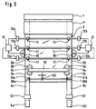
- the pulling device 10 comprises in the illustration shown here, a plurality of pairs of drawing rollers 11 which, as in FIG FIG. 3 can be seen, grip the respective border of the glass ribbon 2.
- the glass ribbon 2 is below the bottom Cooling point cooled, so that the redirection into a horizontal Direction can connect.
- the glass has a temperature of 70 ° C when entering the deflection process and a temperature of 40 ° C after the redirection process. They vary with other glass thicknesses Temperatures slightly. The temperature drops during the deflection process approximately linearly. The redirection can also be carried out when the glass ribbon is at room temperature.
- the glass ribbon 2 is used as a vertical glass ribbon 3a designated.
- the bending zone 3b adjoining this is selected so large that that there is a turning radius R of about 1.50 m or more.
- the Redirection is free hanging, i.e. without additional bending roller.
- a transport device 40 with a conveyor belt 41 and drive device 42 rests.
- the transport device 40 there are one Braid trimming device 50 with lasers and optionally Cooling devices and a cutting device 52 are arranged.
- the Cutting device 52 which may also include a cooling device corresponding to the feed rate of the horizontal glass ribbon 3c moved along.
- Edge processing device 54 can be provided.
- the Processing devices 50, 52, 54 preferably work with laser beams 51a, b, 53 and 55a, b, which are only indicated schematically in FIGS. 1 and 2.
- the braid trimming device 50 With the braid trimming device 50, the glass braids 5a, b separated and in the braid section breaking device 57 into the braid pieces 5a ', b' cut.
- the edge is so wide set that any deformations detected by the drawing rollers 11 and can be discarded.
- a sag control with a Monitoring device 30 for the sag of the deflection radius R arranged.
- the Distance sensor 31 is connected to a controller device 32 which again with the drive device 42 of the transport device 40 connected is. If a change in the deflection radius R occurs, the Controller device 32 first checks whether it is a short-term Change or fluctuation. If this is the case, the Change in the deflection radius accepted so that the Transport speed of the horizontal glass ribbon 3c unchanged can be maintained. However, if it is a longer one Should fluctuations act, a correction of the Feed speed can be made.
- corresponding limit values can be entered, preferably first in the event of fluctuations> 10 sec., the feed rate of the horizontal Glass ribbon 3c is changed. A corresponding signal is then sent to the Drive device 42 given so that an adaptation to the change in Deflection radius can be made, so that the Slack in the deflection area back to the original value can be adjusted.
- Such an embodiment can preferably can be realized by a PI controller.
- the order of the devices 52, 50 and 54 is interchanged.
- the cutting device 52 is a cutting device.
- the individual disks 4 are formed (see also FIG. 1). Since in Fig. 2 the scratching of the glass ribbon by means of the cutting device 52 before trimming in the trimming device 50 takes place, the borders 5a, b automatically break in during the border trimming individual braid pieces 5a ', b'.
- FIG. 3 there is a device 20 on each of the side borders 6a, b arranged to monitor the vertical alignment of the glass ribbon.
- This device is explained in more detail in connection with FIGS. 4 to 8.
- This monitoring device 20 is connected to a controller device 21 connected, which in turn with the drive devices 12a and 12b Pull roller pairs 11 is linked. In the event of a deviation from straightness can thus be individually controlled and by the pulling roller pairs 11 a change in the difference in drawing speed can affect straightness be returned to the target orientation.
- FIG. 4 shows a translational sideways movement of the glass ribbon 2, 3a shown schematically.
- the original vertical orientation is due to the Dashed border 6a ', 6b' shown.
- the glass ribbon is around one certain amount migrated to the right, so that now the position of Braid 6a, 6b is taken.
- There is one on the right border Monitoring device 20 is arranged, which has a holder 23 on of the three rollers 22a, b, c are arranged.
- the distance between the rollers is chosen as large as possible to make even minor changes in the To be able to detect braid shift. While the two rollers 22a, b are arranged stationary with respect to the holder 23, the middle roller 22b slidably mounted and coupled to a first displacement sensor 24a.
- the roller 22b is by means of a spring of force F2 against the border 6b of the Glass ribbon 2 pressed.
- the bracket 23 is with a lever linkage 25 a fixed support member 27 connected.
- the entire roller holder 23 and thus also the three have been shown Rollers 22a, b, c from their dashed position to the position shown emotional. This deviation is detected by the displacement sensor 24b. Both sensors 24a, b are connected to a computer unit 26.
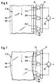
- FIG. 2 Another problem is shown in FIG. It is about this involves bending the glass borders 6a, b. While the rollers 22a, c hardly changed their position, the middle roller 22b is clearly to the left deflected, which is detected by the displacement sensor 24a. By corresponding signals from sensors 24a and 24b to those in connection With the controller device 21 discussed in FIG. 3, an adaptation of the Drive speed of the drawing rollers 11 are made.
- the roller holder 23 is pressed against the border 6b with a force F1, where F2 is significantly less than F1.
- FIG Monitoring device 20 In Figs. 6 to 8 is another embodiment of FIG Monitoring device 20 shown. Instead of roles there are optical ones or ultrasonic sensors 22a ', b' and c 'on the common fixed Carrier element 27 attached. If there is a lateral offset of the glass ribbon this is demonstrated by the three sensors 22a ', b' and c ', all three the same Measure displacement. These values are sent to the computing unit 26 passed on.
- the bending zone 3b is enlarged to explain the threading shown.
- the vertical glass ribbon 3a is 58 at the front end roughly cut to length (this is not shown) and gripped by a rocker 59, which has vacuum suction devices 60 at its front end with which the Glass tape is detected.
- the rocker 59 is pivoted in the direction of the arrow, so that the glass belt can be fed to the conveyor belt 41.
- the Tangential speed of the rocker 59 is at the belt speed customized. After the transfer to the conveyor belt 41, the glass belt released.
- roller conveyor with rollers 61 which are arranged essentially on a circular path are.
- This roller conveyor is located a few centimeters below the Glass ribbon and serves to redirect the ribbon when a glass breakage should occur.
- the roller conveyor picks up and guides the glass conveyor horizontal feed system too. Then the turning radius downsized so that the glass ribbon lifts off the roller conveyor again. While In normal operation, the glass ribbon in the bending zone 3b is not on this Roll up 61.
Landscapes
- Chemical & Material Sciences (AREA)
- Engineering & Computer Science (AREA)
- Materials Engineering (AREA)
- Organic Chemistry (AREA)
- Re-Forming, After-Treatment, Cutting And Transporting Of Glass Products (AREA)
- Laser Beam Processing (AREA)
Abstract
Description
- Fign. 1,2
- Seitenansichten der Vorrichtung zur Herstellung von Glasscheiben,
- Fig. 3
- eine Draufsicht der in Figur 1 gezeigten Vorrichtung,
- Fign. 4,5
- die Vorrichtung zur Überwachung der vertikalen Ausrichtung des Glasbandes im Falle von zwei typischen Problemstellungen,
- Fign. 6-8
- die Vorrichtung zur Überwachung der vertikalen Ausrichtung gemäß einer weiteren Ausführungsform im Fall von drei typischen Problemstellungen,
- Fig. 9
- eine vergrößerte Darstellung der Biegezone.
- 1
- Formgebungseinrichtung
- 1'
- Abkühlstrecke
- 2
- Glasband
- 3a
- vertikales Glasband
- 3b
- Biegezone
- 3c
- horizontales Glasband
- 4
- Einzelscheibe
- 5a,b
- Glasborte
- 5a',b'
- abgetrenntes Bortenstück
- 6a,b
- Borte
- 6a',b'
- Borte
- 10
- Zieheinrichtung
- 11
- Ziehrollenpaar
- 12a,b
- Antriebseinrichtung
- 20
- Überwachungseinrichtung
- 21
- Reglereinrichtung
- 22a,b,c
- Rollen
- 22a',b',c'
- Ultraschallsensoren
- 23
- Halterung
- 24a,b
- erster und zweiter Verschiebesensor
- 25
- Hebelgestänge
- 26
- Rechnereinheit
- 27
- ortsfestes Trägerelement
- 30
- Überwachungseinrichtung für den Umlenkradius
- 31
- Ultraschallabstandsensor
- 32
- Reglereinrichtung
- 40
- horizontale Transporteinrichtung
- 41
- Transporthand
- 42
- Antriebseinrichtung
- 50
- Bortenbeschneidungseinrichtung
- 51a,b
- Laserstrahl
- 52
- Ablängeinrichtung
- 53
- Laserstrahl
- 54
- Kantenbearbeitungseinrichtung
- 55a,b
- Laserstrahl
- 56
- Ablängbrecheinrichtung
- 57
- Bortenabschnittbrecheinrichtung
- 58
- vorderes Ende
- 59
- Schwinge
- 60
- Vakuumsauger
- 61
- Rolle
Claims (25)
- Verfahren zur Herstellung von Einzelglasscheiben der Dicke zwischen 0,03 mm und 2 mm, insbesondere von Glasscheiben für elektronische Geräte, bei dem ein Glasband vertikal aus einer Heißformgebungseinrichtung nach unten abgezogen wird und einer Schneidbearbeitung, die eine Bortenbeschneidung und/oder das Ablängen der Scheiben vom Glasband umfaßt, sowie gegebenenfalls Folgeprozessen unterzogen wird, dadurch gekennzeichnet,daß nach dem Abziehen das vertikale Glasband auf eine Temperatur unterhalb des unteren Kühlpunktes des Glases abgekühlt und anschließend unter Einhaltung eines Umlenkradius von zwischen 0,1 m und 4 m frei hängend in die Horizontale überführt wird, unddaß mindestens eine Schneidbearbeitung am horizontalen Glasband ausgeführt wird.
- Verfahren nach Anspruch 1, dadurch gekennzeichnet, daß die vertikale Ausrichtung des Glasbandes ständig überwacht wird.
- Verfahren nach Anspruch 1 oder 2, dadurch gekennzeichnet, daß bei Glasscheiben einer Dicke zwischen 0,4 mm und 2 mm ein Umlenkradius von 1,5 m bis 4 m eingehalten wird.
- Verfahren nach Anspruch 1 oder 2, dadurch gekennzeichnet, daß bei Glsscheiben einer Dicke zwischen 0,03 mm und 0,4 mm ein Umlenkradius zwischen 0,1 m und 1,5 m eingehalten wird.
- Verfahren nach Anspruch 4, dadurch gekennzeichnet, daß nach der Bortenbeschneidung das Glasband aufgewickelt wird.
- Verfahren nach einem der Ansprüche 1 bis 5, dadurch gekennzeichnet, daß sowohl das Ablängen als auch die Bortenbeschneidung am horizontalen Glasband ausgeführt wird.
- Verfahren nach einem der Ansprüche 1 bis 6, dadurch gekennzeichnet, daß das Glasband so weit abgekühlt wird, daß es während der Umlenkung in die Horizontale eine Temperatur zwischen 30 und 80° C aufweist.
- Verfahren nach einem der Ansprüche 1 bis 7, dadurch gekennzeichnet, daß die Vorschubgeschwindigkeit des horizontalen Glasbandes unter Berücksichtigung des Umlenkradius geregelt wird.
- Verfahren nach einem der Ansprüche 1 bis 8, dadurch gekennzeichnet, daß die Vorschubgeschwindigkeit des horizontalen Glasbandes erst nach lang anhaltenden Änderungen des Umlenkradius von mehr als 8 bis 12 Sekunden zur Einstellung des ursprünglichen Umlenkradius verändert wird.
- Verfahren nach einem der Ansprüche 1 bis 9, dadurch gekennzeichnet, daß die vertikale Ausrichtung des Glasbandes an mindestens einer Borte überwacht wird.
- Verfahren nach einem der Ansprüche 1 bis 10, dadurch gekennzeichnet, daß bei der Überwachung der vertikalen Ausrichtung des Glasbandes sowohl translatorische Bewegungen des gesamten Glasbandes in der Bandebene als auch Durchbiegungen der Glasborte erfaßt und durch Anpassung der Ziehgeschwindigkeit oder der Differenz der Ziehgeschwindigkeit an den beiden Glasborten geregelt werden.
- Verfahren nach einem der Ansprüche 1 bis 11, dadurch gekennzeichnet, daß die Schneidbearbeitung mittels Laserstrahlen durchgeführt wird.
- Verfahren nach einem der Ansprüche 1 bis 12, dadurch gekennzeichnet, daß das Schneidwerkzeug zum Ablängen der Scheiben entsprechend der Vorschubgeschwindigkeit des Glasbandes bewegt wird.
- Verfahren nach einem der Ansprüche 1 bis 13, dadurch gekennzeichnet, daß nach der Bortenbeschneidung und vor dem Ablängen die Kanten bearbeitet werden.
- Verfahren nach einem der Ansprüche 1 bis 14, dadurch gekennzeichnet, daß beim Kantenbearbeiten und/oder Bortenbeschneiden das Glas zugspannungsfrei gehalten wird.
- Vorrichtung zur Herstellung von Einzelglasscheiben einer Dicke zwischen 0,03 mm und 2 mm, insbesondere von Glasscheiben für elektronische Geräte, mit einer Formgebungseinrichtung, einer vertikalen, abwärts arbeitenden Zieheinrichtung und mindestens einer Schneideinrichtung zur Bortenbeschneidung und zum Ablängen der Scheiben, dadurch gekennzeichnet,daß im Bereich der vertikalen Zieheinrichtung (10) Sensoren (22a,b,c,22a',b',c') zur Überwachung der vertikalen Ausrichtung des Glasbandes (2) angeordnet sind, die über eine Reglereinrichtung (21) mit der Zieheinrichtung (10) verbunden sind,daß unterhalb der Zieheinrichtung (10) eine horizontale Transporteinrichtung (40) angeordnet ist, wobei mindestens die Schneideinrichtung (52) zum Ablängen im Bereich der horizontalen Transporteinrichtung (40) angeordnet sind,daß zwischen der Zieheinrichtung (10) und der Transporteinrichtung (40) eine Biegezone (3b) vorgesehen ist, in der das Glasband (2) frei hängend in die Horizontale umgelenkt wird, unddaß im Bereich der Biegezone (3b) eine Einrichtung (30) zur Überwachung des Umlenkradius des frei hängenden Glasbandes angeordnet ist.
- Vorrichtung nach Anspruch 16, dadurch gekennzeichnet, daß die Ablängeinrichtung (52) mindestens einen Laser aufweist.
- Vorrichtung nach Anspruch 16 oder 17, dadurch gekennzeichnet, daß in die Ablängeinrichtung (52) eine Kantenbearbeitungseinrichtung (54) integriert ist.
- Vorrichtung nach einem der Ansprüche 16 bis 18, dadurch gekennzeichnet, daß die Sensoren (22a,b,c,22a',b',c') mechanische, optische oder Ultraschall-Sensoren sind.
- Vorrichtung nach einem der Ansprüche 16 bis 19, dadurch gekennzeichnet, daß die Einrichtung (30) zur Überwachung des Umlenkradius des Glasbandes mindestens einen in radialer Richtung angeordneten Ultraschallabstandssensor (31) und eine Reglereinrichtung (32) umfaßt.
- Vorrichtung nach Anspruch 20, dadurch gekennzeichnet, daß die Reglereinrichtung (32) mit der Transporteinrichtung (40) verbunden ist.
- Vorrichtung zur Überwachung der vertikalen Ausrichtung der Ränder von kontinuierlich hergestellten vertikalen Glasbändern, gekennzeichnet durch mindestens drei die Glasborte (6b) überwachenden Sensoren (22a,b,c,22a',b',c'), die an einer gemeinsamen Halterung (23) angeordnet sind, die an einem ortsfesten Trägerelement (27) gehalten ist.
- Vorrichtung nach Anspruch 22, dadurch gekennzeichnet, daß die Sensoren durch Rollen (22a,b,c) gebildet sind, die an der Glasborte (6b) anliegen, wobei mindestens eine Rolle (22b) bezüglich der Halterung (23) verschiebbar und die Halterung beweglich an dem ortsfesten Trägerelement (27) gehalten ist, wobei sowohl an der verschiebbaren Rolle (22b) als auch an der Halterung (23) jeweils mindestens ein Verschiebungssensor (24a) angeordnet ist.
- Vorrichtung nach Anspruch 23, dadurch gekennzeichnet, daß die verschiebbare Rolle (22b) zwischen den beiden anderen Rollen (22a,22c) angeordnet ist.
- Vorrichtung nach einem der Ansprüche 22 bis 24, dadurch gekennzeichnet, daß die Halterung (23) aus einem Material besteht, dessen Wärmeausdehnungskoeffizient α im Bereich von Raumtemperatur bis 200°C Null ist.
Applications Claiming Priority (2)
| Application Number | Priority Date | Filing Date | Title |
|---|---|---|---|
| DE19918936 | 1999-04-27 | ||
| DE19918936A DE19918936A1 (de) | 1999-04-27 | 1999-04-27 | Verfahren und Vorrichtung zur Herstellung von Einzelglasscheiben |
Publications (3)
| Publication Number | Publication Date |
|---|---|
| EP1048621A2 true EP1048621A2 (de) | 2000-11-02 |
| EP1048621A3 EP1048621A3 (de) | 2001-05-30 |
| EP1048621B1 EP1048621B1 (de) | 2005-06-08 |
Family
ID=7905912
Family Applications (1)
| Application Number | Title | Priority Date | Filing Date |
|---|---|---|---|
| EP00108626A Expired - Lifetime EP1048621B1 (de) | 1999-04-27 | 2000-04-20 | Verfahren und Vorrichtung zur Herstellung von Einzelglasscheiben |
Country Status (6)
| Country | Link |
|---|---|
| US (1) | US6502423B1 (de) |
| EP (1) | EP1048621B1 (de) |
| JP (1) | JP2000335928A (de) |
| KR (1) | KR100670102B1 (de) |
| DE (2) | DE19918936A1 (de) |
| TW (1) | TW593176B (de) |
Cited By (12)
| Publication number | Priority date | Publication date | Assignee | Title |
|---|---|---|---|---|
| WO2002014229A1 (de) * | 2000-08-16 | 2002-02-21 | Schott Glas | Verfahren und vorrichtung zur herstellung von einzelglasscheiben |
| WO2002051757A3 (de) * | 2000-12-23 | 2002-10-10 | Schott Glas | Verfahren und vorrichtung zum herstellung von dünnen glasscheiben |
| WO2008045241A2 (en) | 2006-10-04 | 2008-04-17 | Corning Incorporated | Method and apparatus for proof testing a sheet of brittle material |
| CN102811960A (zh) * | 2009-11-30 | 2012-12-05 | 康宁股份有限公司 | 用于分离平板玻璃的装置和方法 |
| CN103038183A (zh) * | 2010-08-02 | 2013-04-10 | 日本电气硝子株式会社 | 玻璃膜的割断方法 |
| WO2013050165A1 (de) * | 2011-10-07 | 2013-04-11 | Schott Ag | Glasfolie mit glatter und mikorrissfreier oberfläche der kante und deren herstellungsverfahren |
| CN103130407A (zh) * | 2011-11-30 | 2013-06-05 | 康宁股份有限公司 | 用于移除玻璃板的周界部的方法和设备 |
| WO2015135721A1 (de) * | 2014-03-13 | 2015-09-17 | Schott Ag | Verfahren und vorrichtung zur reduzierung der säbeligkeit bei dünngläsern |
| CN112759242A (zh) * | 2021-03-02 | 2021-05-07 | 甘肃光轩高端装备产业有限公司 | 玻璃生产设备和方法 |
| US11155496B2 (en) | 2015-09-11 | 2021-10-26 | Schott Ag | Apparatus and method for stabilizing sheets of a hard brittle material |
| US20220411308A1 (en) * | 2020-01-20 | 2022-12-29 | Nippon Electric Glass Co., Ltd. | Method for producing glass film |
| US20250074810A1 (en) * | 2021-07-20 | 2025-03-06 | Corning Incorporated | Apparatus and methods for separating edge portions from a glass ribbon |
Families Citing this family (93)
| Publication number | Priority date | Publication date | Assignee | Title |
|---|---|---|---|---|
| JP3586142B2 (ja) * | 1999-07-22 | 2004-11-10 | エヌエッチ・テクノグラス株式会社 | ガラス板の製造方法、ガラス板の製造装置、及び液晶デバイス |
| JP4107642B2 (ja) * | 2002-07-11 | 2008-06-25 | ニチアス株式会社 | ディスクロール |
| US20060249553A1 (en) * | 2005-05-06 | 2006-11-09 | Ljerka Ukrainczyk | Ultrasonic induced crack propagation in a brittle material |
| US20070039990A1 (en) * | 2005-05-06 | 2007-02-22 | Kemmerer Marvin W | Impact induced crack propagation in a brittle material |
| EP1721872A1 (de) * | 2005-05-10 | 2006-11-15 | Corning Incorporated | Verfahren zur Herstellung einer Glasscheibe |
| US20060261118A1 (en) * | 2005-05-17 | 2006-11-23 | Cox Judy K | Method and apparatus for separating a pane of brittle material from a moving ribbon of the material |
| US20060280920A1 (en) * | 2005-06-10 | 2006-12-14 | Abbott John S Iii | Selective contact with a continuously moving ribbon of brittle material to dampen or reduce propagation or migration of vibrations along the ribbon |
| US20070095108A1 (en) * | 2005-10-31 | 2007-05-03 | Kirby Thomas E | Methods and apparatus for reducing stress variations in glass sheets produced from a glass ribbon |
| US8017220B2 (en) * | 2006-10-04 | 2011-09-13 | Corning Incorporated | Electronic device and method of making |
| JP4621996B2 (ja) * | 2007-04-24 | 2011-02-02 | 日本電気硝子株式会社 | ガラス板製造方法およびガラス板製造設備 |
| WO2009093505A1 (ja) * | 2008-01-25 | 2009-07-30 | Asahi Glass Company, Limited | ガラス樹脂複合体の製造方法 |
| US8053704B2 (en) * | 2008-05-27 | 2011-11-08 | Corning Incorporated | Scoring of non-flat materials |
| JP5532506B2 (ja) * | 2008-10-01 | 2014-06-25 | 日本電気硝子株式会社 | ガラスロール |
| JP5435267B2 (ja) * | 2008-10-01 | 2014-03-05 | 日本電気硝子株式会社 | ガラスロール、ガラスロールの製造装置、及びガラスロールの製造方法 |
| JP5532507B2 (ja) * | 2008-10-01 | 2014-06-25 | 日本電気硝子株式会社 | ガラスロール及びガラスロールの処理方法 |
| JP5691148B2 (ja) * | 2008-10-01 | 2015-04-01 | 日本電気硝子株式会社 | ガラスロール、ガラスロールの製造装置、及びガラスロールの製造方法 |
| US8656738B2 (en) * | 2008-10-31 | 2014-02-25 | Corning Incorporated | Glass sheet separating device |
| US8899078B2 (en) * | 2008-11-26 | 2014-12-02 | Corning Incorporated | Glass sheet stabilizing system, glass manufacturing system and method for making a glass sheet |
| TWI517922B (zh) * | 2009-05-13 | 2016-01-21 | 康寧公司 | 切割脆性材料之方法 |
| US8539795B2 (en) * | 2009-05-13 | 2013-09-24 | Corning Incorporated | Methods for cutting a fragile material |
| KR101549721B1 (ko) * | 2009-05-27 | 2015-09-02 | 코닝 인코포레이티드 | 고온에서의 유리의 레이저 스코어링 |
| US8146388B2 (en) * | 2009-10-29 | 2012-04-03 | Corning Incorporated | Low friction edge roll to minimize force cycling |
| US8528364B2 (en) * | 2010-01-08 | 2013-09-10 | Corning Incorporated | Active edge roll control in a glass drawings process |
| KR101736262B1 (ko) | 2010-02-18 | 2017-05-16 | 니폰 덴키 가라스 가부시키가이샤 | 유리 필름의 제조방법 및 그 제조장치 |
| US9656901B2 (en) | 2010-03-03 | 2017-05-23 | Nippon Electric Glass Co., Ltd. | Method of manufacturing a glass roll |
| JP5720885B2 (ja) * | 2010-03-03 | 2015-05-20 | 日本電気硝子株式会社 | ガラスロール、及びガラスロールの製造方法 |
| ES2450520T5 (es) | 2010-03-05 | 2017-08-07 | Sage Electrochromics, Inc. | Laminado de un dispositivo electrocrómico a sustratos de vidrio |
| JP2011190132A (ja) * | 2010-03-12 | 2011-09-29 | Nippon Electric Glass Co Ltd | ガラスロール及びその製造方法 |
| JP5510650B2 (ja) * | 2010-04-14 | 2014-06-04 | 日本電気硝子株式会社 | ガラスフィルムの割断方法及び製造方法 |
| JP5488906B2 (ja) * | 2010-05-20 | 2014-05-14 | 日本電気硝子株式会社 | ガラスフィルムの製造装置及び製造方法 |
| JP5488907B2 (ja) * | 2010-05-20 | 2014-05-14 | 日本電気硝子株式会社 | ガラスフィルムの回収装置及び回収方法 |
| TWI487677B (zh) | 2010-05-28 | 2015-06-11 | Corning Inc | 可撓玻璃的捲狀物及用於捲繞之方法 |
| FR2961609B1 (fr) | 2010-06-21 | 2012-06-01 | Saint Gobain | Dispositif a proprietes optiques et/ou energetiques electrocommandables |
| FR2962818B1 (fr) | 2010-07-13 | 2013-03-08 | Saint Gobain | Dispositif electrochimique a proprietes de transmission optique et/ou energetique electrocommandables. |
| FR2962682B1 (fr) * | 2010-07-16 | 2015-02-27 | Saint Gobain | Vitrage electrochimique a proprietes optiques et/ou energetiques electrocommandables |
| JP5645063B2 (ja) * | 2010-07-23 | 2014-12-24 | 日本電気硝子株式会社 | ガラスフィルムの製造装置および製造方法 |
| TWI571446B (zh) * | 2010-09-30 | 2017-02-21 | 康寧公司 | 一種製作一玻璃片的方法 |
| US9199816B2 (en) * | 2010-11-04 | 2015-12-01 | Corning Incorporated | Methods and apparatus for guiding flexible glass ribbons |
| JP5743182B2 (ja) * | 2010-11-19 | 2015-07-01 | 日本電気硝子株式会社 | ガラスフィルムの製造方法 |
| US8528365B2 (en) * | 2011-02-24 | 2013-09-10 | Corning Incorporated | Apparatus for removing volatilized materials from an enclosed space in a glass making process |
| US9790121B2 (en) | 2011-03-30 | 2017-10-17 | Corning Incorporated | Methods of fabricating a glass ribbon |
| JP5679324B2 (ja) * | 2011-05-19 | 2015-03-04 | 日本電気硝子株式会社 | ガラスロールの製造方法および製造装置 |
| US8794036B2 (en) * | 2011-08-23 | 2014-08-05 | Corning Incorporated | Apparatus and method for separating a glass sheet from a moving ribbon of glass |
| JP2013056813A (ja) * | 2011-09-09 | 2013-03-28 | Nippon Electric Glass Co Ltd | 帯状板ガラスの割断方法及び割断装置 |
| JP5760904B2 (ja) * | 2011-09-28 | 2015-08-12 | 株式会社Ihi | ガラスシート切断装置 |
| TWI586612B (zh) * | 2011-11-18 | 2017-06-11 | 康寧公司 | 用於修整移動玻璃帶之設備及方法 |
| US9315409B2 (en) * | 2011-11-29 | 2016-04-19 | Corning Incorporated | Glass manufacturing apparatus and methods |
| JP5831212B2 (ja) | 2011-12-26 | 2015-12-09 | 日本電気硝子株式会社 | 帯状ガラスの製造方法 |
| US9272941B2 (en) | 2012-04-05 | 2016-03-01 | Sage Electrochromics, Inc. | Method of cutting a panel using a starter crack and a glass panel including a starter crack |
| TW201412658A (zh) * | 2012-09-26 | 2014-04-01 | Corning Inc | 用於可撓式玻璃帶之邊緣修正管理 |
| US8904822B2 (en) * | 2012-11-06 | 2014-12-09 | Corning Incorporated | Thickness control of substrates |
| US9216924B2 (en) * | 2012-11-09 | 2015-12-22 | Corning Incorporated | Methods of processing a glass ribbon |
| US9643878B2 (en) * | 2012-11-13 | 2017-05-09 | Nippon Electric Glass Co., Ltd. | Sheet glass manufacturing method and manufacturing device |
| US9834389B2 (en) | 2012-11-29 | 2017-12-05 | Corning Incorporated | Methods and apparatus for fabricating glass ribbon of varying widths |
| US9266768B2 (en) | 2013-01-21 | 2016-02-23 | Corning Incorporated | High purity nickel molds for optical quality glass forming |
| KR101948382B1 (ko) | 2013-01-30 | 2019-02-14 | 코닝 인코포레이티드 | 가요성 유리의 연속 레이저 절단을 위한 장치 및 방법 |
| US9595398B2 (en) | 2013-08-30 | 2017-03-14 | Corning Incorporated | Low resistance ultracapacitor electrode and manufacturing method thereof |
| US10246365B2 (en) * | 2013-10-09 | 2019-04-02 | Corning Incorporated | Apparatus and method for forming thin glass articles |
| JP2016534963A (ja) * | 2013-11-01 | 2016-11-10 | コーニング インコーポレイテッド | ガラスシートを成形する装置および方法 |
| WO2015083530A1 (ja) * | 2013-12-04 | 2015-06-11 | 旭硝子株式会社 | ガラス板製造装置及び方法 |
| KR20160100917A (ko) | 2013-12-25 | 2016-08-24 | 아사히 가라스 가부시키가이샤 | 유리판의 제조 방법 및 제조 장치 |
| US9260337B2 (en) | 2014-01-09 | 2016-02-16 | Corning Incorporated | Methods and apparatus for free-shape cutting of flexible thin glass |
| US20150251944A1 (en) * | 2014-03-10 | 2015-09-10 | Corning Incorporated | Methods and apparatuses for separating glass ribbons |
| DE102014106817A1 (de) * | 2014-05-14 | 2015-11-19 | Schott Ag | Verfahren und Vorrichtung zur Herstellung eines Dünnglas-Bands und verfahrensgemäß hergestelltes Dünnglas-Band |
| US10570047B2 (en) * | 2014-07-08 | 2020-02-25 | Corning Incorporated | Continuous processing of flexible glass ribbon |
| JP6323716B2 (ja) * | 2014-12-17 | 2018-05-16 | 日本電気硝子株式会社 | ガラスフィルムの製造方法 |
| JP2018508450A (ja) | 2015-01-29 | 2018-03-29 | コーニング インコーポレイテッド | ガラスウェブから各区分を製造する方法および装置 |
| JP2018512362A (ja) * | 2015-03-18 | 2018-05-17 | コーニング インコーポレイテッド | ガラスリボンの縁部を除去するための方法及び装置 |
| TWI687375B (zh) | 2015-03-20 | 2020-03-11 | 美商康寧公司 | 用於成形基於玻璃的材料之模具與製作該模具之方法 |
| JP6945454B2 (ja) * | 2015-05-18 | 2021-10-06 | コーニング インコーポレイテッド | ガラス製造装置における張力制御 |
| CN107635932B (zh) | 2015-05-18 | 2021-12-07 | 康宁股份有限公司 | 用于加工玻璃带的方法和系统 |
| DE102015108553B4 (de) * | 2015-05-29 | 2019-02-14 | Schott Ag | Verfahren und Vorrichtungen zur Reduzierung der Säbeligkeit bei Dünngläsern |
| WO2017007868A1 (en) * | 2015-07-07 | 2017-01-12 | Corning Incorporated | Apparatuses and methods for heating moving glass ribbons at separation lines and/or for separating glass sheets from glass ribbons |
| US10351459B2 (en) | 2015-08-14 | 2019-07-16 | Corning Incorporated | Molds and methods to control mold surface quality |
| WO2017087204A1 (en) | 2015-11-18 | 2017-05-26 | Corning Incorporated | Powder, process of making the powder, and articles made therefrom |
| US10870601B2 (en) | 2015-12-01 | 2020-12-22 | Corning Incorporated | Glass web separating devices and methods |
| JP6669988B2 (ja) * | 2016-06-02 | 2020-03-18 | 日本電気硝子株式会社 | ガラスフィルムの製造方法 |
| CN109804222B (zh) * | 2016-12-06 | 2021-12-10 | 日本电气硝子株式会社 | 带状玻璃膜的品质检查方法 |
| CN110337716A (zh) | 2017-02-27 | 2019-10-15 | Sage电致变色显示有限公司 | 包括基板和透明导电层的电气设备及形成电气设备的方法 |
| JP6748920B2 (ja) * | 2017-03-13 | 2020-09-02 | 日本電気硝子株式会社 | ガラスフィルムの製造方法 |
| TWI753183B (zh) | 2017-07-12 | 2022-01-21 | 美商康寧公司 | 製造玻璃基板的設備及方法 |
| EP3707104B1 (de) | 2017-11-06 | 2024-05-15 | Sage Electrochromics, Inc. | Artikel mit einer nicht lichtemittierenden variablen übertragungsvorrichtung und einer beschichtung |
| JP7324424B2 (ja) * | 2018-01-31 | 2023-08-10 | 日本電気硝子株式会社 | ガラスロール、ガラスロールの製造方法および品質評価方法 |
| DE102019129036A1 (de) * | 2019-10-28 | 2021-04-29 | Schott Ag | Verfahren zur Herstellung von Glasscheiben und verfahrensgemäß hergestellte Glasscheibe sowie deren Verwendung |
| JP7486044B2 (ja) * | 2020-03-17 | 2024-05-17 | 日本電気硝子株式会社 | 帯状ガラスフィルムの製造方法 |
| DE102020118532A1 (de) * | 2020-07-14 | 2022-01-20 | Schott Ag | Vorrichtung und Verfahren zum Längenschnitt bei Dünnstgläsern |
| US12441647B2 (en) * | 2020-11-24 | 2025-10-14 | Corning Incorporated | Methods and apparatus for manufacturing a glass ribbon |
| US20230373842A1 (en) * | 2020-11-24 | 2023-11-23 | Corning Incorporated | System and methods for manufacturing a glass ribbon |
| CN112592032A (zh) * | 2020-12-16 | 2021-04-02 | 成都中光电科技有限公司 | 一种液晶玻璃成型监测玻璃基板弓型的方法及装置 |
| CN113199519A (zh) * | 2021-06-07 | 2021-08-03 | 无锡市凌铭机械科技有限公司 | 蜂窝芯切纸机 |
| KR20230010130A (ko) * | 2021-07-09 | 2023-01-18 | 코닝 인코포레이티드 | 유리 와인딩 시스템, 유리 롤들을 형성하기 위한 시스템 및 방법 |
| CN114348374B (zh) * | 2021-12-02 | 2023-07-14 | 镇江北新建材有限公司 | 检测封边带状态的板材封边系统和检测装置 |
| CN115304253B (zh) * | 2022-06-20 | 2024-03-29 | 杭州乾智坤达新材料科技有限公司 | 一种柔性玻璃生产设备及其生产工艺 |
Family Cites Families (13)
| Publication number | Priority date | Publication date | Assignee | Title |
|---|---|---|---|---|
| US1592444A (en) * | 1924-03-22 | 1926-07-13 | Libbey Owens Sheet Glass Co | Drawing sheet glass |
| US1593567A (en) | 1925-10-29 | 1926-07-27 | Clarence P Byrnes | Glass shaping or feeding |
| US2505103A (en) * | 1943-02-26 | 1950-04-25 | Pittsburgh Plate Glass Co | Method of making plate glass |
| US3191857A (en) * | 1959-11-02 | 1965-06-29 | Pittsburgh Plate Glass Co | Glass partitioning process and apparatus |
| FR1399639A (fr) * | 1964-04-06 | 1965-05-21 | Saint Gobain | Perfectionnement à la découpe d'un ruban continu, notamment de verre |
| LU60747A1 (de) * | 1970-04-17 | 1972-03-03 | ||
| JPS5973440A (ja) | 1982-10-20 | 1984-04-25 | Nippon Sheet Glass Co Ltd | 中間素材入りガラス板の製造装置 |
| DE3329843A1 (de) * | 1983-08-18 | 1984-01-05 | Eglasstrek Patent Promotion & Awarding GmbH, 6203 Hochheim | Verfahren und vorrichtung zur herstellung von flachglas |
| JPH02217327A (ja) * | 1989-02-15 | 1990-08-30 | Nippon Electric Glass Co Ltd | ガラス板製造方法 |
| DE19649488A1 (de) * | 1996-11-29 | 1997-11-06 | Schott Glaswerke | Vorrichtung zur Handhabung von dünnen Glasscheiben |
| DE19715537C2 (de) * | 1997-04-14 | 1999-08-05 | Schott Glas | Verfahren und Vorrichtung zum Durchtrennen von flachen Werkstücken aus sprödem Material, insbesondere aus Glas |
| JPH10338548A (ja) * | 1997-04-30 | 1998-12-22 | Agfa Gevaert Nv | ロール上に薄いガラスを製造するための方法 |
| US6098862A (en) * | 1998-05-18 | 2000-08-08 | Lucent Technologies Inc. | Incrementally continuous laser cleaving process |
-
1999
- 1999-04-27 DE DE19918936A patent/DE19918936A1/de not_active Withdrawn
-
2000
- 2000-04-20 EP EP00108626A patent/EP1048621B1/de not_active Expired - Lifetime
- 2000-04-20 DE DE50010492T patent/DE50010492D1/de not_active Expired - Fee Related
- 2000-04-25 KR KR1020000021942A patent/KR100670102B1/ko not_active Expired - Fee Related
- 2000-04-26 US US09/557,834 patent/US6502423B1/en not_active Expired - Fee Related
- 2000-04-27 JP JP2000126923A patent/JP2000335928A/ja active Pending
- 2000-05-31 TW TW089108020A patent/TW593176B/zh not_active IP Right Cessation
Cited By (24)
| Publication number | Priority date | Publication date | Assignee | Title |
|---|---|---|---|---|
| KR100720894B1 (ko) * | 2000-08-16 | 2007-05-22 | 쇼오트 아게 | 개별 유리 판 제조 방법 및 장치 |
| WO2002014229A1 (de) * | 2000-08-16 | 2002-02-21 | Schott Glas | Verfahren und vorrichtung zur herstellung von einzelglasscheiben |
| WO2002051757A3 (de) * | 2000-12-23 | 2002-10-10 | Schott Glas | Verfahren und vorrichtung zum herstellung von dünnen glasscheiben |
| CN100361912C (zh) * | 2000-12-23 | 2008-01-16 | 肖特股份有限公司 | 薄玻璃板的制造方法和装置 |
| KR100821932B1 (ko) * | 2000-12-23 | 2008-04-15 | 쇼오트 아게 | 박판 유리 제조방법 및 제조장치 |
| WO2008045241A2 (en) | 2006-10-04 | 2008-04-17 | Corning Incorporated | Method and apparatus for proof testing a sheet of brittle material |
| EP2069752B1 (de) * | 2006-10-04 | 2020-04-29 | Corning Incorporated | Verfahren und vorrichtung zur abnahmeprüfung einer scheibe aus sprödem material |
| CN102811960B (zh) * | 2009-11-30 | 2015-01-21 | 康宁股份有限公司 | 用于分离平板玻璃的装置和方法 |
| CN102811960A (zh) * | 2009-11-30 | 2012-12-05 | 康宁股份有限公司 | 用于分离平板玻璃的装置和方法 |
| CN103038183B (zh) * | 2010-08-02 | 2015-05-20 | 日本电气硝子株式会社 | 玻璃膜的割断方法 |
| EP2548852A4 (de) * | 2010-08-02 | 2013-12-18 | Nippon Electric Glass Co | Verfahren zum schneiden eines glasfilms |
| CN103038183A (zh) * | 2010-08-02 | 2013-04-10 | 日本电气硝子株式会社 | 玻璃膜的割断方法 |
| WO2013050165A1 (de) * | 2011-10-07 | 2013-04-11 | Schott Ag | Glasfolie mit glatter und mikorrissfreier oberfläche der kante und deren herstellungsverfahren |
| CN103130407B (zh) * | 2011-11-30 | 2015-09-02 | 康宁股份有限公司 | 用于移除玻璃板的周界部的方法和设备 |
| TWI593650B (zh) * | 2011-11-30 | 2017-08-01 | 康寧公司 | 用於移除玻璃片之周圍部分的方法及設備 |
| CN103130407A (zh) * | 2011-11-30 | 2013-06-05 | 康宁股份有限公司 | 用于移除玻璃板的周界部的方法和设备 |
| WO2015135721A1 (de) * | 2014-03-13 | 2015-09-17 | Schott Ag | Verfahren und vorrichtung zur reduzierung der säbeligkeit bei dünngläsern |
| US11312649B2 (en) | 2014-03-13 | 2022-04-26 | Schott Ag | Method and apparatus for reducing the camber in thin glasses |
| US11155496B2 (en) | 2015-09-11 | 2021-10-26 | Schott Ag | Apparatus and method for stabilizing sheets of a hard brittle material |
| DE102016116259B4 (de) * | 2015-09-11 | 2025-01-09 | Schott Ag | Vorrichtung und Verfahren zur Stabilisierung von Scheiben eines sprödharten Materials |
| US20220411308A1 (en) * | 2020-01-20 | 2022-12-29 | Nippon Electric Glass Co., Ltd. | Method for producing glass film |
| US12421152B2 (en) * | 2020-01-20 | 2025-09-23 | Nippon Electric Glass Co., Ltd. | Method for producing glass film |
| CN112759242A (zh) * | 2021-03-02 | 2021-05-07 | 甘肃光轩高端装备产业有限公司 | 玻璃生产设备和方法 |
| US20250074810A1 (en) * | 2021-07-20 | 2025-03-06 | Corning Incorporated | Apparatus and methods for separating edge portions from a glass ribbon |
Also Published As
| Publication number | Publication date |
|---|---|
| KR100670102B1 (ko) | 2007-01-16 |
| TW593176B (en) | 2004-06-21 |
| EP1048621B1 (de) | 2005-06-08 |
| EP1048621A3 (de) | 2001-05-30 |
| JP2000335928A (ja) | 2000-12-05 |
| KR20010049290A (ko) | 2001-06-15 |
| US6502423B1 (en) | 2003-01-07 |
| DE19918936A1 (de) | 2000-11-02 |
| DE50010492D1 (de) | 2005-07-14 |
Similar Documents
| Publication | Publication Date | Title |
|---|---|---|
| EP1048621B1 (de) | Verfahren und Vorrichtung zur Herstellung von Einzelglasscheiben | |
| DE102016116258B4 (de) | Vorrichtung und Verfahren zur Belastungsprüfung von Scheiben eines sprödharten Materials | |
| DE102013109443B4 (de) | Verfahren zum Ziehen von Glasbändern | |
| DE102020118532A1 (de) | Vorrichtung und Verfahren zum Längenschnitt bei Dünnstgläsern | |
| DE102015120566A1 (de) | Verfahren und Vorrichtung zum Ritzen von Dünnglas sowie angeritztes Dünnglas | |
| DE102016116259B4 (de) | Vorrichtung und Verfahren zur Stabilisierung von Scheiben eines sprödharten Materials | |
| EP2563533B1 (de) | Minimierung des bandzugs eines walzgutes zwischen zwei walzeinheiten | |
| DE112019003147T5 (de) | Glasrollenherstellungsverfahren | |
| CN104936908A (zh) | 对连续玻璃带进行加工的方法 | |
| DE112019000619T5 (de) | Glasrolle, Glasrollenherstellungsverfahren und Qualitätsbewertungsverfahren | |
| DE10237478B4 (de) | Verfahren zum Schneiden eines fortlaufenden Glasbandes bei der Herstellung von Flachglas | |
| EP0433956A1 (de) | Drahtsäge zum Abtrennen von Scheiben von stab- oder blockförmigen Werkstücken und ihre Verwendung | |
| DE69906369T2 (de) | Verfahren und vorrichtung zum herstellen einer gebogenen glasplatte | |
| DE112021001653T5 (de) | Verfahren zur herstellung eines streifenförmigen glasfilms | |
| EP0744492B1 (de) | Kalander | |
| DE102004035649B4 (de) | Verfahren und Vorrichtung zum Aufbringen von parallelen Folienstreifen auf eine Materialbahn | |
| DE102018131179A1 (de) | Glaselement mit geschnittener Kante und Verfahren zu dessen Herstellung | |
| DE102016208964B4 (de) | Schneidvorrichtung und Verfahren zum Beschneiden von Faserhalbzeugen, sowie Ablegesystem zum Ablegen von Faserhalbzeugen | |
| EP2431153A2 (de) | Verfahren zum Inline-Steuerung bei Folienanlagen | |
| DE69315643T2 (de) | Zerteilen von Glasscheiben | |
| WO2024256288A2 (de) | Vorrichtung, verfahren und separatorbahn für die energiezellen, insbesondere batteriezellen, produzierende industrie | |
| DE102009042019A1 (de) | Verfahren und Vorrichtung zum Abtrennen von Folienstücken von einer Folienbahn mit zugelastischen Eigenschaften | |
| DE69108880T2 (de) | Verfahren und Vorrichtung zum Herstellen von gebogen Glasscheiben. | |
| DE112021000639T5 (de) | Verfahren zur herstellung eines glasfilms | |
| DE112020005790T5 (de) | Verfahren zur herstellung von glasrollen |
Legal Events
| Date | Code | Title | Description |
|---|---|---|---|
| PUAI | Public reference made under article 153(3) epc to a published international application that has entered the european phase |
Free format text: ORIGINAL CODE: 0009012 |
|
| 17P | Request for examination filed |
Effective date: 20000420 |
|
| AK | Designated contracting states |
Kind code of ref document: A2 Designated state(s): DE |
|
| AX | Request for extension of the european patent |
Free format text: AL;LT;LV;MK;RO;SI |
|
| RAP1 | Party data changed (applicant data changed or rights of an application transferred) |
Owner name: SCHOTT DISPLAYGLAS GMBH |
|
| PUAL | Search report despatched |
Free format text: ORIGINAL CODE: 0009013 |
|
| AK | Designated contracting states |
Kind code of ref document: A3 Designated state(s): AT BE CH CY DE DK ES FI FR GB GR IE IT LI LU MC NL PT SE |
|
| AX | Request for extension of the european patent |
Free format text: AL;LT;LV;MK;RO;SI |
|
| RAP1 | Party data changed (applicant data changed or rights of an application transferred) |
Owner name: CARL-ZEISS-STIFTUNG TRADING AS SCHOTT GLAS Owner name: SCHOTT GLAS |
|
| AKX | Designation fees paid |
Free format text: DE |
|
| 17Q | First examination report despatched |
Effective date: 20040319 |
|
| GRAP | Despatch of communication of intention to grant a patent |
Free format text: ORIGINAL CODE: EPIDOSNIGR1 |
|
| RAP1 | Party data changed (applicant data changed or rights of an application transferred) |
Owner name: SCHOTT AG |
|
| GRAS | Grant fee paid |
Free format text: ORIGINAL CODE: EPIDOSNIGR3 |
|
| GRAA | (expected) grant |
Free format text: ORIGINAL CODE: 0009210 |
|
| AK | Designated contracting states |
Kind code of ref document: B1 Designated state(s): DE |
|
| REF | Corresponds to: |
Ref document number: 50010492 Country of ref document: DE Date of ref document: 20050714 Kind code of ref document: P |
|
| PLBE | No opposition filed within time limit |
Free format text: ORIGINAL CODE: 0009261 |
|
| STAA | Information on the status of an ep patent application or granted ep patent |
Free format text: STATUS: NO OPPOSITION FILED WITHIN TIME LIMIT |
|
| 26N | No opposition filed |
Effective date: 20060309 |
|
| PGFP | Annual fee paid to national office [announced via postgrant information from national office to epo] |
Ref country code: DE Payment date: 20090513 Year of fee payment: 10 |
|
| PG25 | Lapsed in a contracting state [announced via postgrant information from national office to epo] |
Ref country code: DE Free format text: LAPSE BECAUSE OF NON-PAYMENT OF DUE FEES Effective date: 20101103 |