EP1042644B1 - Vorrichtung zum bestimmen der rad- und/oder achsgeometrie von kraftfahrzeugen - Google Patents
Vorrichtung zum bestimmen der rad- und/oder achsgeometrie von kraftfahrzeugen Download PDFInfo
- Publication number
- EP1042644B1 EP1042644B1 EP98966793A EP98966793A EP1042644B1 EP 1042644 B1 EP1042644 B1 EP 1042644B1 EP 98966793 A EP98966793 A EP 98966793A EP 98966793 A EP98966793 A EP 98966793A EP 1042644 B1 EP1042644 B1 EP 1042644B1
- Authority
- EP
- European Patent Office
- Prior art keywords
- measuring
- wheel
- vehicle
- image recording
- features
- Prior art date
- Legal status (The legal status is an assumption and is not a legal conclusion. Google has not performed a legal analysis and makes no representation as to the accuracy of the status listed.)
- Expired - Lifetime
Links
Images

Classifications
-
- G—PHYSICS
- G01—MEASURING; TESTING
- G01B—MEASURING LENGTH, THICKNESS OR SIMILAR LINEAR DIMENSIONS; MEASURING ANGLES; MEASURING AREAS; MEASURING IRREGULARITIES OF SURFACES OR CONTOURS
- G01B11/00—Measuring arrangements characterised by the use of optical techniques
- G01B11/26—Measuring arrangements characterised by the use of optical techniques for measuring angles or tapers; for testing the alignment of axes
- G01B11/275—Measuring arrangements characterised by the use of optical techniques for measuring angles or tapers; for testing the alignment of axes for testing wheel alignment
- G01B11/2755—Measuring arrangements characterised by the use of optical techniques for measuring angles or tapers; for testing the alignment of axes for testing wheel alignment using photoelectric detection means
-
- G—PHYSICS
- G01—MEASURING; TESTING
- G01B—MEASURING LENGTH, THICKNESS OR SIMILAR LINEAR DIMENSIONS; MEASURING ANGLES; MEASURING AREAS; MEASURING IRREGULARITIES OF SURFACES OR CONTOURS
- G01B2210/00—Aspects not specifically covered by any group under G01B, e.g. of wheel alignment, caliper-like sensors
- G01B2210/10—Wheel alignment
- G01B2210/14—One or more cameras or other optical devices capable of acquiring a two-dimensional image
- G01B2210/146—Two or more cameras imaging the same area
-
- G—PHYSICS
- G01—MEASURING; TESTING
- G01B—MEASURING LENGTH, THICKNESS OR SIMILAR LINEAR DIMENSIONS; MEASURING ANGLES; MEASURING AREAS; MEASURING IRREGULARITIES OF SURFACES OR CONTOURS
- G01B2210/00—Aspects not specifically covered by any group under G01B, e.g. of wheel alignment, caliper-like sensors
- G01B2210/10—Wheel alignment
- G01B2210/16—Active or passive device attached to the chassis of a vehicle
-
- G—PHYSICS
- G01—MEASURING; TESTING
- G01B—MEASURING LENGTH, THICKNESS OR SIMILAR LINEAR DIMENSIONS; MEASURING ANGLES; MEASURING AREAS; MEASURING IRREGULARITIES OF SURFACES OR CONTOURS
- G01B2210/00—Aspects not specifically covered by any group under G01B, e.g. of wheel alignment, caliper-like sensors
- G01B2210/10—Wheel alignment
- G01B2210/20—Vehicle in a state of translatory motion
-
- G—PHYSICS
- G01—MEASURING; TESTING
- G01B—MEASURING LENGTH, THICKNESS OR SIMILAR LINEAR DIMENSIONS; MEASURING ANGLES; MEASURING AREAS; MEASURING IRREGULARITIES OF SURFACES OR CONTOURS
- G01B2210/00—Aspects not specifically covered by any group under G01B, e.g. of wheel alignment, caliper-like sensors
- G01B2210/10—Wheel alignment
- G01B2210/30—Reference markings, reflector, scale or other passive device
- G01B2210/303—Reference markings, reflector, scale or other passive device fixed to the ground or to the measuring station
Definitions
- the invention relates to a device for determining the wheel and Axle geometry of motor vehicles in a measuring room with at least one an optical measuring device having an optical image recording device, with a marking device, the one existing or arranged on the wheel Measurement feature arrangement, at least three measurement features per wheel and at least one reference feature arrangement with at least three reference features per image recording position, and with an evaluation device, the position of the reference features in the measuring space in the evaluation device is known and the marking device by means of the measuring device can be recorded from at least two different perspectives.
- Such a device for determining the wheel and axle geometry of Motor vehicles are specified in US-A 5,675,515.
- this known Device are wheel features on the wheels and on the wheels receiving Platforms reference features on both sides of the vehicle to be measured arranged.
- the features on each side of the vehicle are from a separate camera from only one perspective.
- the Cameras on both sides of the vehicle are connected mechanically rigidly coupled together.
- Another device for determining the wheel and axle geometry is in the DE-A 42 12 426 indicated.
- the corresponding wheel is outside its axis with an optically recordable marking, the captured while rotating the wheel with two synchronized television cameras becomes.
- the spatial positions of the markings on the wheels become the Relative positions of the associated axes determined.
- the television cameras are arranged symmetrically to the axis of the corresponding wheel, the vehicle stands on rollers and the wheels turn in roller prisms.
- the invention has for its object a device of the aforementioned Type to provide with the more statements about the wheel and axle geometry with simplified operation and the corrections on Chassis allows during the measurement (e.g. above the work pit).
- the at least one image recording device for recording a part of the same measurement characteristics sufficient at least for the evaluation and reference features from the two different perspectives is, and that the evaluation device is designed such that for Determination of the wheel and axle geometry, the relative location of the different Perspectives by means of the at least one image recording device measurement characteristics recorded together with the reference characteristics can be determined is.
- the driving axis and following wheel and Computed axis geometry data in the evaluation device are determined automatically: single track for each wheel, Total track for each pair of wheels, camber for each wheel, front / rear wheel offset, Lateral offset right / left, track width difference, axle offset, steering angle, Caster, spread and track difference angle as well as the position of the space control axle as a function of the steering angle of each steered wheel, positioning the image recording device because of the inclusion of the reference features is extremely simple.
- the reference features known in the evaluation device can first determine the camera position and simultaneously or subsequently the relative position of the measurement features to the reference features is determined what the values of the wheel and axle geometries are to let win. An adjustment of the image recording device is not required.
- the measures for reliable recording of the reference characteristics are still advantageous that the reference features and / or the measurement features as retroreflective marks are formed and that the image recording device is a camera.
- An inexpensive construction of the device results from the fact that with static Measuring task only one image recording device is provided, which is sequential at two different positions for the respective common recording all wheels of the vehicle or sequentially at two different positions each Vehicle side for the common detection of all wheels on this vehicle side, or can be positioned sequentially at two different positions per wheel and that the sequentially acquired image data by means of the evaluation device can be saved and evaluated.
- a Measuring unit with at least two image recording devices is provided in only one position for the common detection of all wheels of the vehicle or sequentially on both sides of the vehicle at only one position to the common Detection of all wheels on each side of the vehicle or sequentially at only one position can be arranged per wheel, and that by means of the evaluation device sequentially captured image data can be stored and evaluated.
- a further simplified operation is achieved in that two measuring units each with at least two image recording devices are provided, that the two measuring units are placed on both sides of the vehicle, that they each grasp the wheels of one side of the vehicle, or that the two Measuring units are placed on one side of the vehicle so that each one Wheel detected and both sides of the vehicle are sequentially detected, or that the two measuring units are placed so that one wheel of a vehicle axle be detected on both sides of the vehicle, and the vehicle axles sequentially are detected and that by means of the evaluation device sequentially captured image data can be stored and evaluated and further characterized in that four measuring units with at least two image recording devices each simultaneous detection of four wheels of the vehicle are provided.
- a measuring unit comprises at least three cameras.
- At least one light source is used, the detectability of the Measurement features and the reference features still favored.
- At least one Favored light source in the vicinity of the lens of the image recording device (s) the detectability of retroreflective measurement and reference features.
- the light sources are infrared light-emitting diodes, so there is an impairment the lighting conditions for the device operators at the measuring location avoided.
- the wheels or even several vehicles can be differentiated automatically be that at least one measuring mark per wheel or per vehicle carries a code that can be detected by the image recording device.
- coding at least one of the attached wheel brands is in particular also possible, the amount of a shape error of a rim of the corresponding wheel brand clearly assignable and in the subsequent measurements or evaluations to take into account or to correct.
- the device has no absolute Relation to a normal direction, but only relative references to the reference arrangement of the measuring station. Therefore, the requirements for Flatness of the measuring station reduced to the level required by the vehicle become.
- the specification of the geometry data obtained is not limited to angular units, these can also be specified as absolute length units.
- the adjustment of the measuring device previously required in some systems There is no wheel.
- the positioning of the optical image recording device at an angle against a wheel / wheels and the reference arrangement can be easily done roughly and easily controlled, for example, by positioning aids become.
- the measured value acquisition itself takes place in fractions of a second, for everyone Measured variables given a high accuracy with a large measuring range is.
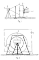
- Fig. 1 shows a device for determining the wheel and axle geometry of a Vehicle with a measuring unit arranged on the side of the wheel 5 on a tripod 1 and a reference feature arrangement arranged between this and the wheel 5 3.
- the measuring unit 1 in the present case two image recording devices in the form of cameras 2 capture an image section 6 in which both the wheel 5 and the reference feature arrangement 3 are at least partially.
- the reference feature arrangement 3 has a trapezoidal shape Has frame with several reference marks 4 and that on the rim flange of the wheel 5 distributed in the circumferential direction a plurality of measuring marks 8 are.
- the front wheel shown in FIGS. 1 and 2 stands on a rotating plate 7 in order to be able to easily perform a steering movement.
- the reference feature arrangement 3 comprises at least three reference marks 4, while on the Wheel 5 at least three measuring marks 8 are attached.
- the reference marks 4 and the measuring marks 3 are preferably retroreflective. Also one Steering axis 9 is specified.
- the exemplary circular, optically diffusely reflecting reference marks 4 and measuring marks 8 have a diameter which is dependent on the Image scale of the camera lens, the size of e.g. as a CCD receiver trained receiver element and the object distance selected is.
- the measuring marks 8 are only approximately evenly distributed over the wheel circumference an adjustment is not necessary.
- the measuring head 1 contains at least two CCD cameras 2, which are different Angle and at a sufficiently large distance the wheel 5 and in particular Detect the attached reference marks 4 and measuring marks 8. It is it is advantageous to achieve a high measuring accuracy, the marks of the Illuminate camera 2. This can be done relatively easily with around the lens arranged around light sources z. B. happen in the form of light emitting diodes (LEDs), which advantageously light in the infrared range or in the near infrared range send out, which affects the lighting conditions for Device operator at the measuring location is avoided.
- LEDs light emitting diodes
- the vehicle Before the actual measurement, the vehicle must be lifted so that the wheels turn freely. Then the measuring unit in the form of the measuring head 1 is on the side to position the wheel 5.
- a measurement for determining the position of the measuring marks 8 is related the wheel axis of rotation started.
- the picture is taken in at least three different wheel rotation positions or the wheel in question is in Rotation offset and (sufficiently quickly) in at least three rotation angle positions added.
- From the pictures taken for each measuring mark 8 the position with respect to the axis of rotation and the plane of rotation with known Triangulation method determined.
- the planes of rotation of all measuring marks 8 are identical. Discrepancies between the Rotation levels indicate existing rim imperfections. Become general this formal error is called rim runout.
- This measurement is to be carried out on each wheel 5, it being advantageous to to attach at least one differently coded measuring mark 8 to each wheel 5, so the wheels 5 (possibly also several vehicles) automatically from each other to be able to distinguish.
- this measuring station assigns the known embodiments, the four reference feature arrangements 3, the span the measuring room above the measuring station with the reference marks attached to it 4, whose spatial coordinates (relative to each other) by previous ones Surveying are known.
- the trapezoidal frame or a differently shaped frame with the in on a flat surface or reference marks arranged spatially offset from one another 4 is anchored to the ground in the area of the wheel 5 and, if desired, can be hinged or slidably attached. It must be ensured that they are brought into a known, measured position. How 3 shows such reference feature arrangements 3 next to each wheel 5 arranged or arrangeable so that the vehicle easily between them can be positioned.
- the wheel and axle geometry data use either only one measuring head 1 with two cameras 2 sequential recordings (at least one per camera) made from each wheel 5 and in an evaluation device saved or the measurement is done by arranging several measuring heads 1 on several wheels at the same time 5. Also only one camera 2 is sufficient can be moved to at least two different measuring positions in order to in two successive measurement processes, the reference marks 4 and to detect the measuring marks 8. For example, from a suitable Position above the vehicle (or in front or behind) also with all four wheels 5 the correspondingly attached measuring marks 8 are detected when the Measuring marks 8 correspondingly far above on the wheels 5 by means of holders are attached.
- the measuring head 1 Before the start of the recordings, the measuring head 1 is laterally next to the wheel 5 and the reference feature arrangement 3 roughly to be positioned so that the wheel 5 and the reference feature arrangement 3 (or a sufficient part thereof) from the cameras 2 of the measuring head 1 and a maximum distance from the wheel 5 is not exceeded.
- the measuring head is preferably used to support the Operator with a corresponding positioning aid (measuring surface / object space and distance).
- the saved recordings are now with known methods of image processing and triangulation evaluated so that the coordinates of the measuring marks 8 attached to the wheel 5 in relation to the Reference feature arrangement 3 can be obtained.
- the vehicle coordinate system e.g. vehicle longitudinal axis / plane or travel axis
- wheel and axle geometry data can be calculated: track for each wheel, total track, camber for each wheel, wheel offset front / rear, side offset right / left, track width difference and axis offset.
- This geometry data is available as angle sizes, but can also be in units of length can be specified.
- the track gauge can also be entered in this information be included.
- Points of the body in the area of the wheel cutout
- Points of the body can also be the Deflection state or loading state per wheel 5 and / or the inclination of the Body in the longitudinal and transverse directions can be detected. It is possible Deviations from a predetermined uniformity of the loading condition quickly recognized and, if necessary, by appropriate loading / unloading to correct or take them into account in vehicle-specific correction calculations.
- the determination of further wheel or steering geometry data on the steered wheels 5 happens as usual by turning the wheels 5 by a defined steering angle.
- the steering angle is the change the coordinates of the measuring marks 8 attached to the wheel 5 are determined, as are the Values for caster, spread and track differential angle and position of the space control axis as a function of the steering angle.
- the axis of rotation is not only in its angles, but also in its spatial position in the Measuring station recorded. That is why the rolling radius of the wheels can be extended Specify caster and spread in units of length. It is advantageous for the determination this geometry data laterally next to each steered wheel 5 Measuring head 1 positioned so that the results for these wheels 5 at the same time can be displayed.
- the device is designed with only one measuring head 1, then the measurement must be carried out be performed on each wheel 5 in succession.
- At least three characteristic points or characteristic edges as reference or measuring elements are used for the acquisition and image processing, which are identified by means of the evaluation device and their geometric Location is determined.
Applications Claiming Priority (3)
| Application Number | Priority Date | Filing Date | Title |
|---|---|---|---|
| DE19757763A DE19757763A1 (de) | 1997-12-23 | 1997-12-23 | Vorrichtung zum Bestimmen der Rad- und/oder Achsgeometrie von Kraftfahrzeugen |
| DE19757763 | 1997-12-23 | ||
| PCT/DE1998/003743 WO1999034166A1 (de) | 1997-12-23 | 1998-12-21 | Vorrichtung zum bestimmen der rad- und/oder achsgeometrie von kraftfahrzeugen |
Publications (2)
| Publication Number | Publication Date |
|---|---|
| EP1042644A1 EP1042644A1 (de) | 2000-10-11 |
| EP1042644B1 true EP1042644B1 (de) | 2004-07-28 |
Family
ID=7853315
Family Applications (1)
| Application Number | Title | Priority Date | Filing Date |
|---|---|---|---|
| EP98966793A Expired - Lifetime EP1042644B1 (de) | 1997-12-23 | 1998-12-21 | Vorrichtung zum bestimmen der rad- und/oder achsgeometrie von kraftfahrzeugen |
Country Status (10)
| Country | Link |
|---|---|
| US (1) | US6404486B1 (zh) |
| EP (1) | EP1042644B1 (zh) |
| JP (1) | JP4406506B2 (zh) |
| KR (1) | KR100570457B1 (zh) |
| CN (1) | CN1183372C (zh) |
| BR (1) | BR9814339A (zh) |
| DE (2) | DE19757763A1 (zh) |
| ES (1) | ES2226202T3 (zh) |
| RU (1) | RU2223463C2 (zh) |
| WO (1) | WO1999034166A1 (zh) |
Cited By (1)
| Publication number | Priority date | Publication date | Assignee | Title |
|---|---|---|---|---|
| CN101178305B (zh) * | 2006-10-25 | 2011-06-15 | 弥荣精机株式会社 | 车轮定位测量装置 |
Families Citing this family (60)
| Publication number | Priority date | Publication date | Assignee | Title |
|---|---|---|---|---|
| DE19757763A1 (de) | 1997-12-23 | 1999-07-01 | Bosch Gmbh Robert | Vorrichtung zum Bestimmen der Rad- und/oder Achsgeometrie von Kraftfahrzeugen |
| US7065462B2 (en) * | 1998-07-24 | 2006-06-20 | Merilab, Inc. | Vehicle wheel alignment by rotating vision sensor |
| WO2000060308A1 (de) * | 1999-03-30 | 2000-10-12 | Siemens Aktiengesellschaft | Verfahren zur einstellung der achsengeometrie eines fahrzeugs, mit einstellvorrichtung und fertigungslinie zur durchführung des verfahrens |
| DE19934864A1 (de) * | 1999-07-24 | 2001-02-08 | Bosch Gmbh Robert | Vorrichtung zum Bestimmen der Rad- und/oder Achsgeometrie von Kraftfahrzeugen |
| DE19937035B4 (de) * | 1999-08-05 | 2004-09-16 | Daimlerchrysler Ag | Vorrichtung und Verfahren zur dreidimensionalen zeitaufgelösten photogrammetrischen Erfassung eines Objekts |
| DE19949704A1 (de) * | 1999-10-15 | 2001-05-10 | Bosch Gmbh Robert | Verfahren und Einrichtung zum Bewerten des Spieles in Lagern oder Gelenken miteinander gekoppelter Bauteile |
| BE1013152A3 (nl) | 1999-11-24 | 2001-10-02 | Krypton Electronic Eng Nv | Werkwijze voor het bepalen van het dynamisch gedrag van een voertuig op een testbank. |
| DE10032356A1 (de) * | 2000-07-04 | 2002-01-31 | Bosch Gmbh Robert | Vorrichtung zum Ermitteln von Rad-, Achsgeometriedaten und/oder Bewegungsdaten der Karosserie eines Fahrzeugs |
| AUPR529901A0 (en) * | 2001-05-28 | 2001-06-21 | Lynx Engineering Consultants Pty Ltd | Automated wheel skid detector |
| DE10135362C1 (de) * | 2001-07-20 | 2002-10-10 | Daimler Chrysler Ag | Verfahren zur Beurteilung der Fahrwerksgeometrie |
| EP1466137B1 (en) * | 2001-12-28 | 2010-04-14 | Rudolph Technologies, Inc. | Stereoscopic three-dimensional metrology system and method |
| CA2455066C (en) * | 2003-01-09 | 2007-01-09 | Garry Stopa | Method of and apparatus for the inspection of vehicle wheel alignment |
| EP1588126B1 (en) * | 2003-01-27 | 2008-06-18 | Snap-on Technologies, Inc. | Calibration certification for wheel alignment equipment |
| DE10308042B4 (de) * | 2003-02-26 | 2007-01-04 | Deutsches Zentrum für Luft- und Raumfahrt e.V. | Verfahren zur Bestimmung des Verlaufs einer beliebig geformten Linie im Raum |
| US7278215B2 (en) * | 2003-07-28 | 2007-10-09 | Honda Motor Co., Ltd. | Method and device for measuring wheel alignment of automobile |
| US20050060899A1 (en) * | 2003-09-23 | 2005-03-24 | Snap-On Technologies, Inc. | Invisible target illuminators for 3D camera-based alignment systems |
| US7265821B1 (en) * | 2003-10-29 | 2007-09-04 | Burke E. Porter Machinery Company | Caster angle measurement system for vehicle wheels |
| DE102004013441A1 (de) | 2004-03-18 | 2005-10-13 | Beissbarth Gmbh | Meßverfahren und Meßgerät zur Bestimmung der räumlichen Lage einer Radfelge sowie Fahrwerkvermessungseinrichtung |
| DE102005017624A1 (de) | 2005-04-15 | 2006-10-19 | Robert Bosch Gmbh | Verfahren zum Bestimmen der Rad- und/oder Achsgeometrie von Kraftfahrzeugen |
| ITRE20050043A1 (it) * | 2005-04-26 | 2006-10-27 | Corghi Spa | Metodo e dispositivo per determinare l'assetto delle ruote di un veicolo |
| US7454841B2 (en) * | 2005-11-01 | 2008-11-25 | Hunter Engineering Company | Method and apparatus for wheel alignment system target projection and illumination |
| DE102005063082A1 (de) | 2005-12-29 | 2007-07-05 | Robert Bosch Gmbh | Verfahren zur optischen Fahrwerksvermessung |
| DE102005063051A1 (de) | 2005-12-29 | 2007-07-05 | Robert Bosch Gmbh | Verfahren zur optischen Fahrwerksvermessung |
| DE102005063083A1 (de) * | 2005-12-29 | 2007-07-05 | Robert Bosch Gmbh | Verfahren zur optischen Fahrwerksvermessung |
| US7710555B2 (en) | 2006-06-27 | 2010-05-04 | Burke E. Porter Machinery Company | Apparatus and method for determining the orientation of an object such as vehicle wheel alignment |
| DE102006035232A1 (de) * | 2006-07-26 | 2008-01-31 | Robert Bosch Gmbh | Optische Messeinrichtung mit einer Bildaufnahmeeinheit |
| DE102006041822A1 (de) * | 2006-09-06 | 2008-03-27 | Beissbarth Gmbh | Verfahren zur Fahrwerksmessung eines Kraftfahrzeugs, Fahrwerksvermessungseinrichtung sowie Kraftfahrzeugprüfstrasse |
| DE102006058383A1 (de) | 2006-12-08 | 2008-06-12 | Robert Bosch Gmbh | Verfahren zur optischen Fahrwerksvermessung |
| DE102007011459A1 (de) * | 2007-03-09 | 2008-09-11 | Zf Friedrichshafen Ag | Kraftfahrzeug und Verfahren zum Einstellen antriebsstrangseitiger Baugruppen desselben |
| US7864309B2 (en) | 2007-05-04 | 2011-01-04 | Burke E. Porter Machinery Company | Non contact wheel alignment sensor and method |
| DE102007047424A1 (de) | 2007-10-04 | 2009-04-09 | Robert Bosch Gmbh | Kraftfahrzeugbauteil-Vermessungssystem, Verwendung sowie Verfahren |
| SE531784C2 (sv) * | 2007-10-11 | 2009-08-04 | Jonas Samuelsson | Förfarande och anordning för hjulmätning |
| ES2388188T3 (es) * | 2008-01-09 | 2012-10-10 | Siemens Aktiengesellschaft | Centrado de vehículo en el estado de ajuste del mecanismo de traslación y procedimiento correspondiente |
| DE102008006329A1 (de) | 2008-01-28 | 2009-07-30 | Robert Bosch Gmbh | Verfahren und Vorrichtung zum Überprüfen der Referenzierung von Messköpfen eines Fahrwerksvermessungssystems |
| DE102008001339A1 (de) | 2008-04-23 | 2009-10-29 | Robert Bosch Gmbh | Verfahren und Vorrichtung zur Fahrwerksvermessung |
| DE102008024395A1 (de) * | 2008-05-20 | 2009-12-03 | Universität Karlsruhe (Th) | Verfahren zur Objekterfassung |
| EP2329221B1 (de) * | 2008-09-12 | 2015-10-14 | Robert Bosch GmbH | Targetanordnung, satz von target-anordnungen und vorrichtung zur optischen achsvermessung |
| DE102008042024A1 (de) * | 2008-09-12 | 2010-03-18 | Robert Bosch Gmbh | Verfahren und Vorrichtung zur optischen Achsvermessung von Kraftfahrzeugen |
| DE102008054975A1 (de) | 2008-12-19 | 2010-07-01 | Robert Bosch Gmbh | Verfahren zur Fahrwerksvermessung sowie Vorrichtung zum Vermessen der Fahrwerksgeometrie eines Fahrzeugs |
| JP5387202B2 (ja) * | 2009-07-23 | 2014-01-15 | 横浜ゴム株式会社 | タイヤ解析システムおよびタイヤ解析方法 |
| RU2557643C2 (ru) * | 2010-02-26 | 2015-07-27 | Йосам Аб | Способ и система для определения углов установки колес транспортного средства |
| DE102010003461A1 (de) * | 2010-03-30 | 2011-10-06 | Robert Bosch Gmbh | Verfahren zur Bestimmung der Taumelbewegung eines Fahrzeugrades |
| DE102010029058A1 (de) * | 2010-05-18 | 2011-11-24 | Robert Bosch Gmbh | Verfahren und Vorrichtung zur Bestimmung einer Achsgeometrie eines Fahrzeugs |
| DE102010038905A1 (de) * | 2010-08-04 | 2012-02-09 | Robert Bosch Gmbh | Verfahren und Vorrichtung zum Bestimmen von Rad- und Karosseriebewegungen eines Fahrzeuges |
| CN102636358A (zh) * | 2012-05-03 | 2012-08-15 | 营口瀚为科技有限公司 | 大型及重型多轴车辆做四轮定位的方法 |
| US9665793B2 (en) | 2013-03-15 | 2017-05-30 | Hunter Engineering Company | Method for determining parameters of a rotating object within a projected pattern |
| CN103398677B (zh) * | 2013-08-20 | 2015-09-16 | 长春设备工艺研究所 | 一种可进行馈线高度调节的滞后角精密检测装置 |
| CN104483144B (zh) * | 2014-12-18 | 2017-09-05 | 厦门大学 | 一种鲁棒的基于机器视觉的汽车3d四轮定位参数检测方法 |
| WO2018060963A1 (en) | 2016-09-30 | 2018-04-05 | Burke E. Porter Machinery Company | Wheel alignment measurement method and system for vehicle wheels |
| DE102016118593A1 (de) * | 2016-09-30 | 2018-04-05 | Dürr Assembly Products GmbH | Vorrichtung zur Erfassung der Lenkradstellung, des Lenkradeinschlagwinkels und/oder der Neigung des Lenkrades eines Fahrzeugs |
| JP6792927B2 (ja) * | 2017-04-14 | 2020-12-02 | 一般財団法人電力中央研究所 | 三次元形状の計測方法 |
| PL3425328T3 (pl) * | 2017-07-07 | 2022-02-14 | Car-O-Liner Group AB | Sposób określania kątów wrzeciona |
| US11466982B2 (en) | 2017-11-27 | 2022-10-11 | Cemb S.P.A. | Method and apparatus for measuring the dimensions and characteristic angles of wheels, steering system and chassis of vehicles |
| US11781860B2 (en) | 2018-04-30 | 2023-10-10 | BPG Sales and Technology Investments, LLC | Mobile vehicular alignment for sensor calibration |
| US11624608B2 (en) | 2018-04-30 | 2023-04-11 | BPG Sales and Technology Investments, LLC | Vehicular alignment for sensor calibration |
| US11243074B2 (en) | 2018-04-30 | 2022-02-08 | BPG Sales and Technology Investments, LLC | Vehicle alignment and sensor calibration system |
| US11835646B2 (en) | 2018-04-30 | 2023-12-05 | BPG Sales and Technology Investments, LLC | Target alignment for vehicle sensor calibration |
| US11597091B2 (en) | 2018-04-30 | 2023-03-07 | BPG Sales and Technology Investments, LLC | Robotic target alignment for vehicle sensor calibration |
| CN109737895B (zh) * | 2019-01-29 | 2021-03-30 | 深圳市鹰眼在线电子科技有限公司 | 汽车车轮的定位设备、方法和计算机可读存储介质 |
| EP3719696A1 (en) | 2019-04-04 | 2020-10-07 | Aptiv Technologies Limited | Method and device for localizing a sensor in a vehicle |
Family Cites Families (12)
| Publication number | Priority date | Publication date | Assignee | Title |
|---|---|---|---|---|
| DE2948573A1 (de) * | 1979-12-03 | 1981-06-04 | Siemens AG, 1000 Berlin und 8000 München | Verfahren und anordnung zur beruehrungslosen achsvermessung an kraftfahrzeugen |
| US4639878A (en) * | 1985-06-04 | 1987-01-27 | Gmf Robotics Corporation | Method and system for automatically determining the position and attitude of an object |
| DE4212426C1 (en) * | 1992-04-14 | 1993-07-01 | Wolfgang 3407 Gleichen De Brunk | Measurement of tracking and camber of vehicle wheel axles - recording markers on rotating wheels using synchronised video cameras, image evaluation of marker positions |
| GB2270435A (en) | 1992-09-05 | 1994-03-09 | Ibm | Stereogrammetry |
| US5532816A (en) * | 1994-03-15 | 1996-07-02 | Stellar Industries, Inc. | Laser tracking wheel alignment measurement apparatus and method |
| DE4409198B4 (de) * | 1994-03-17 | 2008-07-17 | Areva Np Gmbh | Einrichtung zur fotografischen Dokumentation einer Anlage |
| FI98958C (fi) * | 1995-04-13 | 1997-09-10 | Spectra Physics Visiontech Oy | Menetelmä säiliön paikantamiseksi säiliön vuorauksen kulumismittauksessa |
| DE19528798C2 (de) * | 1995-08-04 | 2000-04-20 | Schenck Pegasus Gmbh | Vorrichtung zum berührungslosen Bestimmen des Höhenstandes an einem Kraftfahrzeug |
| DE19531652A1 (de) | 1995-08-29 | 1997-05-07 | Bosch Gmbh Robert | Kraftstoffeinspritzventil für Brennkraftmaschinen |
| US5675515A (en) * | 1995-12-28 | 1997-10-07 | Hunter Engineering Company | Apparatus and method for determining vehicle wheel alignment measurements from three dimensional wheel positions and orientations |
| DE69622530T2 (de) * | 1996-04-23 | 2003-03-06 | Gs Srl | Verfahren zur Bestimmung der Fahrzeugradausrichtung |
| DE19757763A1 (de) | 1997-12-23 | 1999-07-01 | Bosch Gmbh Robert | Vorrichtung zum Bestimmen der Rad- und/oder Achsgeometrie von Kraftfahrzeugen |
-
1997
- 1997-12-23 DE DE19757763A patent/DE19757763A1/de not_active Ceased
-
1998
- 1998-12-21 DE DE59811723T patent/DE59811723D1/de not_active Expired - Lifetime
- 1998-12-21 RU RU2000120163/28A patent/RU2223463C2/ru not_active IP Right Cessation
- 1998-12-21 ES ES98966793T patent/ES2226202T3/es not_active Expired - Lifetime
- 1998-12-21 BR BR9814339-5A patent/BR9814339A/pt active Search and Examination
- 1998-12-21 KR KR1020007006972A patent/KR100570457B1/ko not_active IP Right Cessation
- 1998-12-21 EP EP98966793A patent/EP1042644B1/de not_active Expired - Lifetime
- 1998-12-21 US US09/582,380 patent/US6404486B1/en not_active Expired - Lifetime
- 1998-12-21 JP JP2000526774A patent/JP4406506B2/ja not_active Expired - Fee Related
- 1998-12-21 CN CNB988125358A patent/CN1183372C/zh not_active Expired - Fee Related
- 1998-12-21 WO PCT/DE1998/003743 patent/WO1999034166A1/de active IP Right Grant
Cited By (1)
| Publication number | Priority date | Publication date | Assignee | Title |
|---|---|---|---|---|
| CN101178305B (zh) * | 2006-10-25 | 2011-06-15 | 弥荣精机株式会社 | 车轮定位测量装置 |
Also Published As
| Publication number | Publication date |
|---|---|
| KR20010033471A (ko) | 2001-04-25 |
| DE19757763A1 (de) | 1999-07-01 |
| RU2223463C2 (ru) | 2004-02-10 |
| BR9814339A (pt) | 2000-10-03 |
| JP4406506B2 (ja) | 2010-01-27 |
| KR100570457B1 (ko) | 2006-04-13 |
| CN1283265A (zh) | 2001-02-07 |
| ES2226202T3 (es) | 2005-03-16 |
| US6404486B1 (en) | 2002-06-11 |
| JP2002500342A (ja) | 2002-01-08 |
| EP1042644A1 (de) | 2000-10-11 |
| CN1183372C (zh) | 2005-01-05 |
| WO1999034166A1 (de) | 1999-07-08 |
| DE59811723D1 (de) | 2004-09-02 |
Similar Documents
| Publication | Publication Date | Title |
|---|---|---|
| EP1042644B1 (de) | Vorrichtung zum bestimmen der rad- und/oder achsgeometrie von kraftfahrzeugen | |
| EP1042643B1 (de) | Vorrichtung zum bestimmen der rad- und/oder achsgeometrie von kraftfahrzeugen | |
| EP3586080B1 (de) | Vorrichtung und verfahren zum kalibrieren von fahrzeug-assistenz-systemen | |
| EP2321618B1 (de) | Vorrichtung und verfahren zum bestimmen und einstellen der fahrwerksgeometrie eines fahrzeuges | |
| EP2335018B1 (de) | Verfahren und vorrichtung zur optischen achsvermessung von kraftfahrzeugen | |
| EP1204844B1 (de) | Vorrichtung zum bestimmen der rad- und/oder achsgeometrie von kraftfahrzeugen | |
| EP0774646B1 (de) | Verfahren und Vorrichtung zum Vermessen der Achsen und Radstellungen von Kraftfahrzeugen | |
| DE3116253C2 (zh) | ||
| EP1969308B1 (de) | Verfahren zur optischen fahrwerksvermessung | |
| EP2069714B1 (de) | Verfahren zur fahrwerksvermessung eines kraftfahrzeugs, fahrwerksvermessungseinrichtung sowie kraftfahrzeugprüfstrasse | |
| EP1505367A2 (de) | Verfahren zur Bestimmung der Achsgeometrie und Sensor zu dessen Durchführung | |
| EP1969310A2 (de) | Verfahren zur optischen fahrwerksvermessung | |
| EP2064516A1 (de) | Verfahren zur relativen positionierung eines messgegenstands und eines kraftfahrzeugs zu einem messgerät sowie messgerät und fahrwerksvermessungseinrichtung | |
| EP3516363B1 (de) | Scheinwerfereinstellprüfgerät, scheinwerfereinstellprüfplatz, scheinwerfereinstellgerät und verfahren zum prüfen einer scheinwerfereinstellung | |
| DE102019104466A1 (de) | Vorrichtung zur Kraftfahrzeug-Spurmessung und Verfahren zur Kraftfahrzeug-Spurmessung | |
| EP0386401A2 (de) | Vorrichtung zur Messung von Radstellungswerten | |
| EP2839239B1 (de) | Verfahren zur bestimmung der orientierung mindestens einer fahrschiene eines messplatzes und vorrichtung zur durchführung des verfahren | |
| WO2008046706A1 (de) | Verfahren zum vermessen der rad- oder achsgeometrie eines fahrzeugs | |
| WO2007077063A1 (de) | Verfahren und vorrichtung zur berührungslosen messung der achsgeometrie | |
| DE102004004193A1 (de) | Verfahren und Vorrichtung zur Winkeljustage eines Sensors in einem Kraftfahrzeug | |
| WO2020052877A1 (de) | Verfahren und vorrichtung zum ausrichten einer kalibriereinrichtung | |
| EP1930688B1 (de) | Verfahren zur optischen Fahrwerksvermessung | |
| DE69733672T2 (de) | Verfahren zum messen der orientierung einer oberfläche | |
| DE102007019367A1 (de) | Bildgestützte Kalibrierung von Fahrzeug-Tachographen mittels Messmarken | |
| EP3631359A1 (de) | Vorrichtung und verfahren zur fahrzeugvermessung |
Legal Events
| Date | Code | Title | Description |
|---|---|---|---|
| PUAI | Public reference made under article 153(3) epc to a published international application that has entered the european phase |
Free format text: ORIGINAL CODE: 0009012 |
|
| 17P | Request for examination filed |
Effective date: 20000724 |
|
| AK | Designated contracting states |
Kind code of ref document: A1 Designated state(s): DE ES FR GB IT |
|
| RIN1 | Information on inventor provided before grant (corrected) |
Inventor name: UFFENKAMP, VOLKER Inventor name: NOBIS, GUENTER |
|
| 17Q | First examination report despatched |
Effective date: 20030519 |
|
| GRAP | Despatch of communication of intention to grant a patent |
Free format text: ORIGINAL CODE: EPIDOSNIGR1 |
|
| GRAS | Grant fee paid |
Free format text: ORIGINAL CODE: EPIDOSNIGR3 |
|
| GRAA | (expected) grant |
Free format text: ORIGINAL CODE: 0009210 |
|
| AK | Designated contracting states |
Kind code of ref document: B1 Designated state(s): DE ES FR GB IT |
|
| REG | Reference to a national code |
Ref country code: GB Ref legal event code: FG4D Free format text: NOT ENGLISH |
|
| REF | Corresponds to: |
Ref document number: 59811723 Country of ref document: DE Date of ref document: 20040902 Kind code of ref document: P |
|
| REG | Reference to a national code |
Ref country code: ES Ref legal event code: FG2A Ref document number: 2226202 Country of ref document: ES Kind code of ref document: T3 |
|
| ET | Fr: translation filed | ||
| PLBE | No opposition filed within time limit |
Free format text: ORIGINAL CODE: 0009261 |
|
| STAA | Information on the status of an ep patent application or granted ep patent |
Free format text: STATUS: NO OPPOSITION FILED WITHIN TIME LIMIT |
|
| 26N | No opposition filed |
Effective date: 20050429 |
|
| PGFP | Annual fee paid to national office [announced via postgrant information from national office to epo] |
Ref country code: ES Payment date: 20071220 Year of fee payment: 10 |
|
| PGFP | Annual fee paid to national office [announced via postgrant information from national office to epo] |
Ref country code: GB Payment date: 20071220 Year of fee payment: 10 |
|
| PGFP | Annual fee paid to national office [announced via postgrant information from national office to epo] |
Ref country code: FR Payment date: 20071214 Year of fee payment: 10 |
|
| GBPC | Gb: european patent ceased through non-payment of renewal fee |
Effective date: 20081221 |
|
| REG | Reference to a national code |
Ref country code: FR Ref legal event code: ST Effective date: 20090831 |
|
| PG25 | Lapsed in a contracting state [announced via postgrant information from national office to epo] |
Ref country code: GB Free format text: LAPSE BECAUSE OF NON-PAYMENT OF DUE FEES Effective date: 20081221 |
|
| REG | Reference to a national code |
Ref country code: ES Ref legal event code: FD2A Effective date: 20081222 |
|
| PG25 | Lapsed in a contracting state [announced via postgrant information from national office to epo] |
Ref country code: FR Free format text: LAPSE BECAUSE OF NON-PAYMENT OF DUE FEES Effective date: 20081231 Ref country code: ES Free format text: LAPSE BECAUSE OF NON-PAYMENT OF DUE FEES Effective date: 20081222 |
|
| PGFP | Annual fee paid to national office [announced via postgrant information from national office to epo] |
Ref country code: IT Payment date: 20121220 Year of fee payment: 15 |
|
| PGFP | Annual fee paid to national office [announced via postgrant information from national office to epo] |
Ref country code: DE Payment date: 20140221 Year of fee payment: 16 |
|
| REG | Reference to a national code |
Ref country code: DE Ref legal event code: R119 Ref document number: 59811723 Country of ref document: DE |
|
| PG25 | Lapsed in a contracting state [announced via postgrant information from national office to epo] |
Ref country code: IT Free format text: LAPSE BECAUSE OF NON-PAYMENT OF DUE FEES Effective date: 20131231 |
|
| PG25 | Lapsed in a contracting state [announced via postgrant information from national office to epo] |
Ref country code: DE Free format text: LAPSE BECAUSE OF NON-PAYMENT OF DUE FEES Effective date: 20150701 |
|
| PG25 | Lapsed in a contracting state [announced via postgrant information from national office to epo] |
Ref country code: IT Free format text: LAPSE BECAUSE OF NON-PAYMENT OF DUE FEES Effective date: 20131221 |