EP1041177B1 - Verfahren zur elektrochemischen Herstellung von Lithium - Google Patents
Verfahren zur elektrochemischen Herstellung von Lithium Download PDFInfo
- Publication number
- EP1041177B1 EP1041177B1 EP00106014A EP00106014A EP1041177B1 EP 1041177 B1 EP1041177 B1 EP 1041177B1 EP 00106014 A EP00106014 A EP 00106014A EP 00106014 A EP00106014 A EP 00106014A EP 1041177 B1 EP1041177 B1 EP 1041177B1
- Authority
- EP
- European Patent Office
- Prior art keywords
- lithium
- amalgam
- anode
- solid electrolyte
- electrolysis
- Prior art date
- Legal status (The legal status is an assumption and is not a legal conclusion. Google has not performed a legal analysis and makes no representation as to the accuracy of the status listed.)
- Expired - Lifetime
Links
Images

Classifications
-
- C—CHEMISTRY; METALLURGY
- C25—ELECTROLYTIC OR ELECTROPHORETIC PROCESSES; APPARATUS THEREFOR
- C25C—PROCESSES FOR THE ELECTROLYTIC PRODUCTION, RECOVERY OR REFINING OF METALS; APPARATUS THEREFOR
- C25C1/00—Electrolytic production, recovery or refining of metals by electrolysis of solutions
- C25C1/02—Electrolytic production, recovery or refining of metals by electrolysis of solutions of light metals
-
- C—CHEMISTRY; METALLURGY
- C25—ELECTROLYTIC OR ELECTROPHORETIC PROCESSES; APPARATUS THEREFOR
- C25C—PROCESSES FOR THE ELECTROLYTIC PRODUCTION, RECOVERY OR REFINING OF METALS; APPARATUS THEREFOR
- C25C3/00—Electrolytic production, recovery or refining of metals by electrolysis of melts
- C25C3/02—Electrolytic production, recovery or refining of metals by electrolysis of melts of alkali or alkaline earth metals
Definitions
- the present invention relates to an improved method for electrochemical production of metallic lithium from aqueous Lithium salt solutions, which among other things simplified recycling of lithium allows.
- the invention further describes one for carrying out this method suitable electrolysis cell and the principle of a production plant.
- Lithium is an important inorganic basic chemical and has a number of Applications. So it is used to represent organolithium compounds Alloy additive to aluminum or magnesium and for lithium batteries used. Technically, lithium is one by melt flow electrolysis eutectic mixture of lithium chloride and potassium chloride at 400 to 460 ° C manufactured. (Ullmann's Encyclopedia of Industrial Chemistry, Sixth Edition, 1998 Electronic release).
- This process has a high energy consumption (28-32 kWh / kg Li). Moreover the process has the serious disadvantage that only anhydrous lithium chloride can be used. The one primarily present as an aqueous solution Lithium chloride must therefore be used in an energy-intensive process anhydrous solid can be worked up. Since lithium chloride is hygroscopic, the drying and handling requires a special effort.
- a 2 cm salt melt of two alkali metal iodides serves as the electrolyte (preferably LiI and CsI or LiI and KI), while lithium metal is deposited cathodically.
- the current density is between 1 and 4 kA / m 2 without mass transfer limitation occurring.
- EP-B 0497410 describes a method for changing the concentration of lithium in a liquid metal from the group aluminum, copper, zinc, tin and lead by electrochemical means.
- An electrochemical cell is used, which consists of the liquid metal and an electrically conductive material that can absorb lithium. Between these two is a dry electrolyte that can conduct other alkali metal ions in addition to Li ions.
- a direct voltage is now applied so that lithium ions and other ions of the 1st main group from the liquid metal migrate through the dry electrolyte and are absorbed by the electrical conductor.
- the liquid metal is anodically connected, the conductive material on the other side of the dry electrolyte is connected cathodically.
- the following solid electrolytes are used: ⁇ -Al 2 O 3 , ⁇ "- Al 2 O 3 , mixture of Na 2 O and Al 2 O 3 , NASICON and bismuth or a bismuth alloy.
- GB-B 1,155,927 describes a process according to which sodium metal can be obtained from sodium amalgam electrochemically using a solid sodium ion conductor such as beta-Al 2 O 3 with amalgam as the anode and sodium as the cathode.
- a solid sodium ion conductor such as beta-Al 2 O 3
- amalgam as the anode
- sodium as the cathode.
- the implementation of the method described in GB-B 1,155,927 does not lead to the results described there with regard to lithium conversion, product purity and current density when transferred to lithium.
- the system described behaves unstably over the course of a few days if the claimed temperature range is maintained.
- the task was an improved method for electrochemical Production of lithium from aqueous solutions of at least one lithium salt to find about lithium amalgam, which is an energetically more economical production of Lithium allows as the previously used melt flow electrolysis.
- Lithium salt solutions run out for example by dissolving Lithium carbonate can be obtained in hydrochloric acid aqueous solution. It should also be possible to work up Li salt solutions, for example in the synthesis of Li-organic compounds arise as waste streams.
- the lithium metal must be obtained primarily in such a purity that further process steps omitted. For this, the heavy metal content of the lithium must be below 1 ppm.
- the process should be feasible on an industrial scale and must therefore enable sufficiently high current densities and space-time yields.
- lithium amalgam denotes a solution of lithium in Mercury, which is liquid at the reaction temperature.
- the new process is analogous to the existing combination of chlor-alkali electrolysis realizable according to the amalgam process.
- the present invention further relates to a method in which lithium waste, e.g. those from batteries and reaction solutions, reused or as Starting materials for the production of the aqueous used according to the invention
- Solutions of a lithium salt are used.
- Lithium ion batteries can also aqueous solutions of various lithium salts, e.g. lithium halides, Lithium sulfate, lithium sulfonates or lithium salts of organic acids recovered, e.g. be detached.
- Another way of The recovery of such lithium salt solutions is provided by the acidic one Digestion of the electrolytes and electrodes used in batteries with for example hydrochloric acid or sulfuric acid.
- the lithium waste is in one preferred embodiment e.g. using hydrochloric acid in an aqueous Lithium chloride solution transferred.
- the aqueous Li salt solution is electrolyzed in a chlor-alkali amalgam cell in the first stage of the coupled process.
- Chlorine is formed anodically when lithium chloride solutions are used.
- the chlorine is removed as is typical of the process, purified and brought to normal use.
- the process is analogously the recovery of chlorine from sodium chloride by the amalgam process from (Ullmann's Encyclopedia of Industrial Chemistry, 6 th Edition, 1998 Electronic Release).
- oxygen is deposited anodically.
- the brine must then be kept in the pH range from 2 to 4 with base-providing Li salts.
- the lithium is converted into the liquid amalgam in reduced form as metal by the cathode process.
- Mercury or amalgam flows cathodically connected along the bottom of an electrolytic cell.
- a lithium chloride solution with a lithium chloride content of 220 to 350 g / l flows over the mercury.
- the anodic chlorine and the depleted lithium chloride solution (160-210 g / l) are removed from the cell.
- the lithium content in the amalgam is kept at 0.02 to 0.19% by weight (approx. 0.5 to 5 at%), preferably 0.04 to 0.1% by weight (approx. 1 to 3 at%), so that the amalgam remains fluid.
- the outflowing amalgam is conveniently directed over a weir. Titanium is generally used as the anode, but graphite is also possible.
- the current yield is> 90% (based on chlorine), as a rule it is between 95 and 97%.
- the reaction temperature is 50 to 100, preferably 70 to 90 ° C.
- the anode potential becomes like this held that only lithium is anodically oxidized as an ion by the solid electrolyte is transported in the electric field and finally is reduced cathodically to lithium.
- the process according to the invention is carried out in an electrolysis cell in the second stage operated a moving liquid lithium amalgam anode.
- a moving liquid anode which during operation with regard to its Lithium content is depleted, so that it is lithium-rich amalgam, the Z. B. in an electrolysis to obtain lithium amalgam and chlorine Lithium chloride can be obtained is replaced.
- the Concentrated amalgam drain usually passed over a weir to the aqueous one Remove lithium chloride solution. Then the amalgam flow is in a heat exchanger to the operating temperature of the invention Process heated and fed to the hot moving liquid anode. This is expediently carried out in a countercurrent heat exchanger that the hot, depleted amalgam heats the feed.
- the replacement of depleted amalgam can be both discontinuous as well done continuously. In the discontinuous procedure, over batch sales averaged, higher lithium concentrations reached. The continuous operation is easier to carry out operationally. The Disadvantage that the incoming concentrate is usually circulated already diluted lithium amalgam can be diluted be balanced that the process is carried out in several stages.
- the liquid anode is expediently stirred and / or with a Pump in an atmospheric pressure or slightly overpressure Circulation moves.
- the through the exchange-related exchange of amalgam caused movement or thermal convection is compared to that in the required movement negligible and sufficient not reaching the preferred current densities.
- the anode-side power supply is conveniently via the Stainless steel housing of the electrolytic cell, which under the reaction conditions is stable.
- the anode side is suitable against the cathode side electrically isolated.
- the cathode is made of lithium, which is used at the temperatures required for Stabilization of the anode process is required, is present in liquid form.
- the lithium is preferably in the form of a solid Reservoirs introduced into the cathode compartment. At the beginning of the electrolysis it will Lithium then melted. The lithium can also be in liquid form The beginning of the electrolysis can be introduced into the cathode compartment.
- the lithium formed in the process according to the invention can be obtained in a simple manner are discharged from the cathode compartment through an overflow, whereby by Throttling the lithium current ensures that the pressure on the Lithium side is higher than the pressure on the amalgam side. So that becomes a potential mercury contamination of the lithium obtained Micropores or other leaks are suppressed.
- the overpressure of the The cathode compared to the anode is 0.1 to 5 in the process according to the invention bar, preferably 0.5 to 1 bar.
- the cathodic power supply is advantageously carried out via the Lithium filling and the drain pipes or connecting flanges.
- the anode and cathode compartments are helium-tight Lithium ion-conducting solid electrolytes separated from one another.
- ceramic materials or glasses come into consideration.
- lithium- ⁇ "aluminum oxide, lithium- ⁇ -aluminum oxide and lithium- ⁇ / ⁇ " aluminum oxide each based on sodium- ⁇ "aluminum oxide, sodium- ⁇ -aluminum oxide or sodium- ⁇ / ⁇ "-Alumina can be produced by cation exchange.
- Lithium analogs of NASICON ceramics are also preferred.
- the solid electrolyte expediently has the form of a thin-walled, yet pressure-resistant, tube closed on one side (EP-B 0 424 673), on the open end of which an electrically insulating ring is applied by means of a helium-tight, likewise electrically insulating glass solder connection (GB 2 207 545, EP-B 0 482 785).
- the wall thickness of the lithium ion-conducting electrolyte is 0.3 to 5 mm, preferably 1 to 3 mm, particularly preferably 1 to 2 mm.
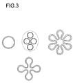
- the cross-sectional shape of the tube closed on one side is circular in the preferred embodiment, in a further embodiment cross-sectional shapes with an enlarged surface are used, which can be derived, for example, from the combination of several circular surfaces, as shown in FIG. 3.
- the execution of the lithium ion-conducting solid electrolyte with regard to its leak tightness has a decisive influence on the method according to the invention, because mercury can only get into the lithium produced via leaks in the solid electrolyte or sealing system, since in the method according to the invention the anode potentials are set so that the formation of mercury ions is excluded becomes.
- solid electrolytes are used which have leak rates of less than 1 * 10 -9 mbar * liter * sec -1 in a helium leak test, i.e. are helium-tight within the detection limit.
- the releasable sealing connections are preferably carried out so that Lithium and amalgam each sealed to the ambient atmosphere become. It is avoided if possible between lithium and amalgam to have removable seals because the removable seals usually do are liquid-tight but not gas-tight and then mercury vapor through the Diffuse removable seal and undesirably contaminate the lithium could.
- In a preferred embodiment come as releasable sealing connections Flat seals for use, preferably made of graphite for Example made from unreinforced GRAPIHIFLEX® or from reinforced high-pressure SIGNAFLEX® from SGL Carbon
- the seals are filled with an inert gas, e.g. Argon or nitrogen washed around to prevent diffusion of oxygen. With helium-tight Electrolytes and the listed sealing arrangement Mercury residual levels of 0.05 to 0.3 ppm obtained in lithium.
- Figure 1 shows a typical experimental setup
- the cell consists in its Core from a tube 1 closed on one side made of lithium ion-conducting Solid electrolyte, the wall thickness of which is preferably 1-3 mm, instead of described 5 mm.
- a ring made of non-conductive Material 2 attached helium-tight using a glass solder connection.
- the ring is the lithium ion conductive tube with the opening upwards in a cylindrical container 3 made of austenitic stainless steel 1.4571 and sealed.
- the ring 2 was with a flat gasket below 4 and above 5 over the housing flange 6 and the cover flange 7 with three clamping screws 8 pressed.
- An anode power supply 9 is attached to the stainless steel container.
- For the Supply of amalgam is a pipe socket 10 on the side, for the drain on the side welded on a pipe socket 11 below.
- a pipe protrudes from the cover flange Stainless steel 13 as cathodic power supply 12 in the opening of the lithium ion conductive tube.
- the same tube 13 is passed through the cover flange and Drilled on the side at the top for the removal of liquid lithium. The whole The apparatus is heated (14).
- the anode is the amalgam filling 15 between the housing and the outer wall of the Lithium ion conductive solid electrolyte tube.
- the anode is constantly replaced by the Magnetic stirrer 16 moves.
- the cathode 17 is the liquid lithium filling inside the lithium ion conductive solid electrolyte tube.
- the liquid formed Lithium is poured into a e.g. by argon 21 inertized vessel 20, partially filled with an inert liquid 22 discharged.
- the ceramic resistance can be reduced by conditioning the Ceramics are made:
- the ceramic resistance can be significantly reduced, for example, if the cell is first operated with reversed polarity, ie the anode is first operated as a cathode.
- the cathode like the anode, can consist of lithium amalgam.
- the current density in the reversed state is increased linearly from 50 A / m 2 to 1000 A / m 2 over a period of 1 to 44 h, preferably 2 to 6 h.
- the current density is generally 0.3 to 10 kA / m 2 , preferably 0.5 to 3 kA / m 2 .
- the current density is specifically set at the external power source, usually a line rectifier.
- the lithium ion-conducting ceramic is as tube closed on one side, which is concentric in the interior a larger outer tube is introduced.
- the outer tube consists of a Material that is very dense and resistant to hot amalgam. Stainless steel and graphite are particularly suitable as materials.
- the Annular gap between the outer tube and ceramic tube is in the longitudinal direction with the flows through liquid anode.
- the gap width of the annular gap is expediently 1 to 10 mm, preferably 2 to 5 mm, particularly preferably 2.5 up to 3 mm.
- the flow rate is 0.03 to 1.0 m / s, preferably 0.05 up to 0.6 m / s, particularly preferably 0.1 to 0.3 m / s.
- a higher one Flow velocity usually allows higher current densities.
- Another design-related advantage of the anode in the form of an annular gap is that relatively small anode volume related to the anode area. So it will possible, the requirement of moderate apparatus weights and an acceptable Mercury current assets.
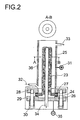
- Figure 2 shows a typical embodiment
- the core of the cell consists of a tube 23 which is closed on one side the lithium ion conductive solid electrolyte. At the open end there is a ring insulating material 24 attached helium-tight by means of a glass solder connection.
- a ring insulating material 24 attached helium-tight by means of a glass solder connection.
- the lithium ion conductive tube With the opening down into a concentric stainless steel tube 25, so that a Annular gap of preferably 2 to 5 mm arises.
- the tube length defined on the one hand fulfills the requirement for a apparatus concept, which manages with a relatively small mercury content.
- the ring cross-section very much permits one in terms of current density effective flow through the anode compartment in the axial direction.
- For sealing is the ring 24 with a flat seal below 26 and 27 above the Housing 28 and the cover flange 29 with three or four clamping screws 30 pressed.
- An anode power supply 31 is attached to the stainless steel container.
- the supply of amalgam is at the bottom a pipe socket 32, for the drain on the side welded on a pipe socket 33 above.
- a pipe protrudes from the cover flange Stainless steel 34 as cathodic power supply 35 in the opening of the Solid electrolyte.
- the same pipe 34 is passed through the cover flange and is used for the free removal of liquid lithium.
- the cell is heated (36).
- the anode is the amalgam filling in the annular space between the inner tube wall and outer wall of the lithium ion conductive solid electrolyte tube.
- the cathode is the liquid lithium filling within the lithium ion conductive Solid electrolyte tube.
- the cell voltage essentially consists of the following two individual contributions: the electrochemical potential of the redox system lithium to lithium amalgam and the ohmic voltage drop via the electrical resistance of the ceramic electrolyte.
- the cell voltage is therefore a function of the current density.
- the electrochemical potential can be measured in the de-energized state. It is set according to the lithium concentration in the liquid anode. With a lithium concentration of 0.05% by weight, for example, a cell voltage of 0.92 V is established in the currentless state. With a current density of 1000 A / m 2 , for example, a cell voltage of 1.95 V is established.
- the cell voltage is monitored and is limited so that anode potentials in which those according to the electrochemical Voltage series of noble metallic impurities in the moving anode could be oxidized.
- the value of cell tension can be an indicator of mass transfer in the liquid moving anode to the ceramic surface and will usually monitored for this.
- the mass transport limitation can be caused due to a too low lithium concentration in the anode and or insufficient flow and or too high current density.
- the current direction is in time intervals from 1 to 24 hours for 1 to 10 minutes reversed by Anode and cathode are short-circuited via an external resistor.
- the Resistance is dimensioned so that the current strength during polarity reversal is about 1.5 times corresponds to the current in operation.
- the yield of won In the method according to the invention, lithium is complete with respect to the Lithium converted on the anode side.
- the current yield of lithium obtained is in normal polarity mode of operation within the measurement accuracy 100%.
- the averaged current yield is reduced due to the intermittent polarity reversal to values from 95% to 98%.
- the amalgam supplied to the anode is in a preferred embodiment depleted from 0.1% by weight to 0.03% by weight of lithium.
- the not implemented Lithium is not lost when coupled with chlor-alkali electrolysis because it is returned to the chlor-alkali cell and via the amalgam cycle of comes back there.
- aqueous lithium salt solutions can be used are preferably an aqueous lithium chloride solution in the composite chloralkali electrolysis.
Description
- Fig. 1:
- Schematische Darstellung einer im Rahmen des erfindungsgemäßen Verfahrens für die zweite Stufe verwendbaren Elektrolysezelle, die einen Rührer umfaßt;
- Fig. 2:
- Schematische Darstellung einer in der 2. Stufe des erfindungsgemäßen Verfahrens verwendbare Elektrolysezelle umfassend einen einseitig geschlossenen rohrförmigen Festelektrolyten, der in ein konzentrisches Edelstahlrohr eingebaut ist;
- Fig. 3:
- Schematische Darstellung der bevorzugten Querschnittsformen des erfindungsgemäß verwendeten Festelektrolyten;
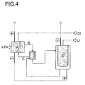
- Fig. 4:
- Schematische Darstellung des erfindungsgemäßen Verfahrens.
Claims (8)
- Verfahren zur Herstellung von metallischem Lithium ausgehend von einer wäßrigen Lösung mindestens eines Lithiumsalzes, das die folgenden Stufen umfaßt:(I) Herstellung eines Lithiumamalgams aus einer wäßrigen Lösung mindestens eines Lithiumsalzes; und(II) Elektrolyse mit einer das Lithiumamalgam enthaltenden Anode, einem heliumdichten Lithiumionen-leitenden Festelektrolyt und flüssigem Lithium als Kathode, dadurch gekennzeichnet, daß Lithiumamalgam als Anode bewegt wird.
- Verfahren nach Anspruch 1, dadurch gekennzeichnet, daß das Lithiumamalgam als Anode durch Rühren und/oder mit einer Pumpe unter Atmosphärendruck oder leichtem Überdruck bewegt wird.
- Verfahren nach Anspruch 1 oder 2, dadurch gekennzeichnet, daß es bei einer Temperatur im Bereich von 250 bis 400 °C durchgeführt wird.
- Verfahren nach einem der Ansprüche 1 bis 3, dadurch gekennzeichnet, daß es bei Stromdichten oberhalb von 250 A/m2 durchgeführt wird.
- Verfahren nach einem der Ansprüche 1 bis 4, dadurch gekennzeichnet, daß das Lithiumamalgam aus der Chloralkali-Elektrolyse stammt.
- Verfahren nach einem der Ansprüche 1 bis 5, dadurch gekennzeichnet, daß der Festelektrolyt ausgewählt wird aus der Gruppe bestehend aus Lithium-β"-AIuminiumoxid, Lithium-β-Aluminiumoxid, Lithium-β/β"-Aluminiumoxid und Lithiumanaloga von NASICON-Keramiken.
- Verfahren nach einem der Ansprüche 1 bis 6, dadurch gekennzeichnet, daß der Festelektrolyt vor der Durchführung des Verfahrens konditioniert wird.
- Verfahren nach einem der Ansprüche 1 bis 7, dadurch gekennzeichnet, daß die wäßrige Lösung des mindestens einen Lithiumsalzes ausgehend von Lithiumabfällen erhalten wird.
Applications Claiming Priority (2)
| Application Number | Priority Date | Filing Date | Title |
|---|---|---|---|
| DE19914221A DE19914221A1 (de) | 1999-03-29 | 1999-03-29 | Verbessertes Verfahren zur elektrochemischen Herstellung von Lithium |
| DE19914221 | 1999-03-29 |
Publications (2)
| Publication Number | Publication Date |
|---|---|
| EP1041177A1 EP1041177A1 (de) | 2000-10-04 |
| EP1041177B1 true EP1041177B1 (de) | 2004-06-16 |
Family
ID=7902823
Family Applications (1)
| Application Number | Title | Priority Date | Filing Date |
|---|---|---|---|
| EP00106014A Expired - Lifetime EP1041177B1 (de) | 1999-03-29 | 2000-03-28 | Verfahren zur elektrochemischen Herstellung von Lithium |
Country Status (8)
| Country | Link |
|---|---|
| US (1) | US6287448B1 (de) |
| EP (1) | EP1041177B1 (de) |
| JP (1) | JP2000290791A (de) |
| CN (1) | CN1198970C (de) |
| AT (1) | ATE269432T1 (de) |
| DE (2) | DE19914221A1 (de) |
| ES (1) | ES2220280T3 (de) |
| RU (1) | RU2250274C2 (de) |
Families Citing this family (20)
| Publication number | Priority date | Publication date | Assignee | Title |
|---|---|---|---|---|
| JP2003270372A (ja) * | 2002-03-12 | 2003-09-25 | Hidetsugu Ikegami | 無反跳非熱核融合反応生成方法及び無反跳非熱核融合エネルギー発生装置 |
| EP1431422B1 (de) * | 2002-12-16 | 2006-12-13 | Basf Aktiengesellschaft | Verfahren zur Gewinnung von Lithium |
| EP1431423A1 (de) * | 2002-12-16 | 2004-06-23 | Basf Aktiengesellschaft | Verfahren zur Herstellung eines Lithiumionenleiters |
| DE102004044404A1 (de) * | 2004-09-14 | 2006-03-30 | Basf Ag | Elektrolysevorrichtung zur Herstellung von Alkalimetall |
| CN103097587B (zh) * | 2010-06-30 | 2017-10-24 | 史蒂文·C·阿门多拉 | 锂金属的电解产物 |
| EP2603620A4 (de) | 2010-08-12 | 2016-10-12 | Res Inst Ind Science & Tech | Verfahren zur extraktion von lithium von hoher reinheit aus einer lithiumhaltigen lösung durch elektrolyse |
| CN102002730A (zh) * | 2010-12-08 | 2011-04-06 | 华东理工大学 | 一种去除锂电解质KCl-LiCl中杂质MgCl2的方法 |
| CN103031567B (zh) * | 2011-10-08 | 2016-04-20 | 中国科学院青岛生物能源与过程研究所 | 一种电解制取金属钠的方法 |
| CN103031568B (zh) * | 2011-10-08 | 2016-04-20 | 中国科学院青岛生物能源与过程研究所 | 一种电解制备金属锂的方法 |
| WO2016073434A1 (en) * | 2014-11-04 | 2016-05-12 | Savannah River Nuclear Solutions, Llc | Recovery of tritium from molten lithium blanket |
| CN104404574B (zh) * | 2014-11-28 | 2016-09-07 | 陈小磊 | 快速上料锂电解槽的上料装置及使用其的锂电解槽 |
| CN104372383B (zh) * | 2014-11-28 | 2017-02-22 | 陈小磊 | 一种锂电解槽上料装置及使用其的锂电解槽 |
| CN104562092B (zh) * | 2015-02-03 | 2017-05-10 | 奉新赣锋锂业有限公司 | 一种多阳极金属锂电解槽 |
| CN104805469B (zh) * | 2015-05-11 | 2017-04-05 | 中国东方电气集团有限公司 | 一种电解制备金属钠装置的阴极电解槽 |
| US11289700B2 (en) | 2016-06-28 | 2022-03-29 | The Research Foundation For The State University Of New York | KVOPO4 cathode for sodium ion batteries |
| US11769906B2 (en) | 2017-09-14 | 2023-09-26 | Ampcera Inc. | Systems and methods for selectively extracting alkaline metals from metal-rich solutions using solid state ionic conductive electrolyte membrane |
| EP3902941A4 (de) * | 2018-12-28 | 2022-11-23 | Yi Cui | Elektrolytische herstellung von hochreinem lithium aus quellen mit niedriger reinheit |
| CN110106526B (zh) * | 2019-05-07 | 2021-05-14 | 清华大学 | 基于固态电解质制备金属锂的方法 |
| RU2742097C1 (ru) * | 2020-07-09 | 2021-02-02 | Акционерное общество "ИНФОТЭК ГРУП" | Способ получения лития путем электролиза из водных растворов, содержащих ионы лития |
| CN113174614B (zh) * | 2021-03-15 | 2023-03-17 | 浙江工业大学 | 一种汞电极电解法回收废旧锂电池锂的方法 |
Family Cites Families (6)
| Publication number | Priority date | Publication date | Assignee | Title |
|---|---|---|---|---|
| GB1155927A (en) | 1967-02-20 | 1969-06-25 | Ici Ltd | Electrolytic manufacture of alkali metals. |
| US4042482A (en) * | 1976-01-22 | 1977-08-16 | E. I. Du Pont De Nemours And Company | Substituted lithium orthosilicates and solid electrolytes therefrom |
| US4089770A (en) * | 1977-07-11 | 1978-05-16 | E. I. Du Pont De Nemours And Company | Electrolytic cell |
| US4156635A (en) * | 1978-03-29 | 1979-05-29 | The United States Of America As Represented By The United States Department Of Energy | Electrolytic method for the production of lithium using a lithium-amalgam electrode |
| BE1005251A3 (nl) | 1991-01-29 | 1993-06-08 | Studiecentrum Kernenergi | Werkwijze voor het langs elektrochemische weg wijzigen van de concentratie van een chemisch element in vloeibaar metaal. |
| EP0835951B1 (de) * | 1996-09-26 | 2002-05-08 | Ngk Spark Plug Co., Ltd. | Verfahren und Vorrichtung zur Gewinnung von Lithium durch Anlegen eines Spannung über einem Lithion-Ionen leitenden Festelektrolyt |
-
1999
- 1999-03-29 DE DE19914221A patent/DE19914221A1/de not_active Withdrawn
-
2000
- 2000-03-20 US US09/531,471 patent/US6287448B1/en not_active Expired - Fee Related
- 2000-03-23 JP JP2000081115A patent/JP2000290791A/ja not_active Withdrawn
- 2000-03-28 EP EP00106014A patent/EP1041177B1/de not_active Expired - Lifetime
- 2000-03-28 DE DE50006784T patent/DE50006784D1/de not_active Expired - Fee Related
- 2000-03-28 ES ES00106014T patent/ES2220280T3/es not_active Expired - Lifetime
- 2000-03-28 AT AT00106014T patent/ATE269432T1/de not_active IP Right Cessation
- 2000-03-28 RU RU2000107367/02A patent/RU2250274C2/ru not_active IP Right Cessation
- 2000-03-29 CN CNB001047965A patent/CN1198970C/zh not_active Expired - Fee Related
Also Published As
| Publication number | Publication date |
|---|---|
| CN1269430A (zh) | 2000-10-11 |
| RU2250274C2 (ru) | 2005-04-20 |
| DE50006784D1 (de) | 2004-07-22 |
| JP2000290791A (ja) | 2000-10-17 |
| EP1041177A1 (de) | 2000-10-04 |
| ATE269432T1 (de) | 2004-07-15 |
| US6287448B1 (en) | 2001-09-11 |
| DE19914221A1 (de) | 2000-10-05 |
| CN1198970C (zh) | 2005-04-27 |
| ES2220280T3 (es) | 2004-12-16 |
Similar Documents
| Publication | Publication Date | Title |
|---|---|---|
| EP1041177B1 (de) | Verfahren zur elektrochemischen Herstellung von Lithium | |
| DE19940069A1 (de) | Verfahren zur elektrochemischen Herstellung eines Alkalimetalls aus wäßriger Lösung | |
| DE975587C (de) | Verfahren und Anordnung zur Herstellung von Titan in einer Elektrolysezelle | |
| EP1794352B1 (de) | Elektrolysezelle zur herstellung von alkalimetall | |
| DE2145504B2 (de) | Verfahren zur Gewinnung von sei tenen Erdmetallen aus ihren Oxyden durch Elektrolyse einer Salzschmelze, und elektroiytische Zelle zur Durch fuhrung dieses Verfahrens | |
| EP1114883B1 (de) | Verfahren und Zelle zur elektrochemischen Herstellung von Alkalimetall aus Alkalimetallamalgam | |
| DE2818971A1 (de) | Verbesserte vorrichtung und verbessertes verfahren zur abtrennung eines metalles aus einem salz | |
| EP1059366B1 (de) | Elektrolysezelle zur Herstellung eines Alkalimetalls | |
| DE2251262C2 (de) | Verfahren zur kontinuierlichen Aluminiumherstellung durch Elektrolyse von Aluminiumchlorid | |
| EP0848764B1 (de) | Verfahren zur elektrochemischen herstellung von natrium und aluminiumchlorid | |
| EP2877614A1 (de) | Verfahren zur herstellung eines alkalimetalls | |
| DE102004044404A1 (de) | Elektrolysevorrichtung zur Herstellung von Alkalimetall | |
| DE2620780A1 (de) | Verfahren zur herstellung von metallischem zink durch schmelzelektrolyse aus zinkchlorid | |
| CH493637A (de) | Verfahren zur Herstellung von Aluminium oder Aluminium-Legierungen | |
| DE2403446C2 (de) | Verfahren zur Herstellung hydrierter Indole | |
| DE2721038C3 (de) | Verfahren zur elektrolytischen Herstellung von Aluminium | |
| Lee et al. | Electrorefining of Indium Metal From Impure In-Sn Alloy in Fluoride Molten Salt | |
| Udupa et al. | Large-scale preparation of perchlorates directly from sodium chloride | |
| DE3811472A1 (de) | Verfahren zur aufarbeitung von metallchloridloesungen | |
| DE1643042B2 (de) | Elektrolyseur zur gewinnung von peroxodischwefelsaeure und deren salze insbesondere solche zur herstellung von wasserstoffperoxid | |
| DE3432684C2 (de) | ||
| WO2024056401A1 (de) | Herstellen von wasserstoff und festem lithiumhydroxid | |
| AT213078B (de) | Verfahren zur kontinuierlichen Erzeugung von Reintantal | |
| WO2019057431A1 (de) | Co2-freie elektrochemische herstellung von metallen und legierungen davon | |
| DE4004575A1 (de) | Verfahren und vorrichtung zur hersellung von hochreinem titan und eines titan-targets fuer die kathodenzerstaeubung |
Legal Events
| Date | Code | Title | Description |
|---|---|---|---|
| PUAI | Public reference made under article 153(3) epc to a published international application that has entered the european phase |
Free format text: ORIGINAL CODE: 0009012 |
|
| AK | Designated contracting states |
Kind code of ref document: A1 Designated state(s): AT BE CH CY DE DK ES FI FR GB GR IE IT LI LU MC NL PT SE |
|
| AX | Request for extension of the european patent |
Free format text: AL;LT;LV;MK;RO;SI |
|
| 17P | Request for examination filed |
Effective date: 20010322 |
|
| AKX | Designation fees paid |
Free format text: AT BE CH CY DE DK ES FI FR GB GR IE IT LI LU MC NL PT SE |
|
| 17Q | First examination report despatched |
Effective date: 20030325 |
|
| GRAP | Despatch of communication of intention to grant a patent |
Free format text: ORIGINAL CODE: EPIDOSNIGR1 |
|
| GRAS | Grant fee paid |
Free format text: ORIGINAL CODE: EPIDOSNIGR3 |
|
| GRAA | (expected) grant |
Free format text: ORIGINAL CODE: 0009210 |
|
| AK | Designated contracting states |
Kind code of ref document: B1 Designated state(s): AT BE CH CY DE DK ES FI FR GB GR IE IT LI LU MC NL PT SE |
|
| PG25 | Lapsed in a contracting state [announced via postgrant information from national office to epo] |
Ref country code: IT Free format text: LAPSE BECAUSE OF FAILURE TO SUBMIT A TRANSLATION OF THE DESCRIPTION OR TO PAY THE FEE WITHIN THE PRESCRIBED TIME-LIMIT;WARNING: LAPSES OF ITALIAN PATENTS WITH EFFECTIVE DATE BEFORE 2007 MAY HAVE OCCURRED AT ANY TIME BEFORE 2007. THE CORRECT EFFECTIVE DATE MAY BE DIFFERENT FROM THE ONE RECORDED. Effective date: 20040616 Ref country code: IE Free format text: LAPSE BECAUSE OF FAILURE TO SUBMIT A TRANSLATION OF THE DESCRIPTION OR TO PAY THE FEE WITHIN THE PRESCRIBED TIME-LIMIT Effective date: 20040616 Ref country code: FI Free format text: LAPSE BECAUSE OF FAILURE TO SUBMIT A TRANSLATION OF THE DESCRIPTION OR TO PAY THE FEE WITHIN THE PRESCRIBED TIME-LIMIT Effective date: 20040616 |
|
| REG | Reference to a national code |
Ref country code: GB Ref legal event code: FG4D Free format text: NOT ENGLISH |
|
| REG | Reference to a national code |
Ref country code: CH Ref legal event code: EP |
|
| REF | Corresponds to: |
Ref document number: 50006784 Country of ref document: DE Date of ref document: 20040722 Kind code of ref document: P |
|
| REG | Reference to a national code |
Ref country code: IE Ref legal event code: FG4D Free format text: GERMAN |
|
| GBT | Gb: translation of ep patent filed (gb section 77(6)(a)/1977) |
Effective date: 20040719 |
|
| PG25 | Lapsed in a contracting state [announced via postgrant information from national office to epo] |
Ref country code: SE Free format text: LAPSE BECAUSE OF FAILURE TO SUBMIT A TRANSLATION OF THE DESCRIPTION OR TO PAY THE FEE WITHIN THE PRESCRIBED TIME-LIMIT Effective date: 20040916 Ref country code: DK Free format text: LAPSE BECAUSE OF FAILURE TO SUBMIT A TRANSLATION OF THE DESCRIPTION OR TO PAY THE FEE WITHIN THE PRESCRIBED TIME-LIMIT Effective date: 20040916 Ref country code: GR Free format text: LAPSE BECAUSE OF FAILURE TO SUBMIT A TRANSLATION OF THE DESCRIPTION OR TO PAY THE FEE WITHIN THE PRESCRIBED TIME-LIMIT Effective date: 20040916 |
|
| REG | Reference to a national code |
Ref country code: ES Ref legal event code: FG2A Ref document number: 2220280 Country of ref document: ES Kind code of ref document: T3 |
|
| REG | Reference to a national code |
Ref country code: IE Ref legal event code: FD4D |
|
| ET | Fr: translation filed | ||
| PG25 | Lapsed in a contracting state [announced via postgrant information from national office to epo] |
Ref country code: LU Free format text: LAPSE BECAUSE OF NON-PAYMENT OF DUE FEES Effective date: 20050328 Ref country code: AT Free format text: LAPSE BECAUSE OF NON-PAYMENT OF DUE FEES Effective date: 20050328 Ref country code: CY Free format text: LAPSE BECAUSE OF FAILURE TO SUBMIT A TRANSLATION OF THE DESCRIPTION OR TO PAY THE FEE WITHIN THE PRESCRIBED TIME-LIMIT Effective date: 20050328 |
|
| PG25 | Lapsed in a contracting state [announced via postgrant information from national office to epo] |
Ref country code: MC Free format text: LAPSE BECAUSE OF NON-PAYMENT OF DUE FEES Effective date: 20050331 |
|
| PLBE | No opposition filed within time limit |
Free format text: ORIGINAL CODE: 0009261 |
|
| STAA | Information on the status of an ep patent application or granted ep patent |
Free format text: STATUS: NO OPPOSITION FILED WITHIN TIME LIMIT |
|
| 26N | No opposition filed |
Effective date: 20050317 |
|
| PGFP | Annual fee paid to national office [announced via postgrant information from national office to epo] |
Ref country code: NL Payment date: 20070304 Year of fee payment: 8 |
|
| PGFP | Annual fee paid to national office [announced via postgrant information from national office to epo] |
Ref country code: DE Payment date: 20070322 Year of fee payment: 8 |
|
| PGFP | Annual fee paid to national office [announced via postgrant information from national office to epo] |
Ref country code: CH Payment date: 20070328 Year of fee payment: 8 Ref country code: GB Payment date: 20070328 Year of fee payment: 8 |
|
| PGFP | Annual fee paid to national office [announced via postgrant information from national office to epo] |
Ref country code: ES Payment date: 20070417 Year of fee payment: 8 |
|
| PGFP | Annual fee paid to national office [announced via postgrant information from national office to epo] |
Ref country code: BE Payment date: 20070514 Year of fee payment: 8 |
|
| PG25 | Lapsed in a contracting state [announced via postgrant information from national office to epo] |
Ref country code: PT Free format text: LAPSE BECAUSE OF NON-PAYMENT OF DUE FEES Effective date: 20041116 |
|
| PGFP | Annual fee paid to national office [announced via postgrant information from national office to epo] |
Ref country code: FR Payment date: 20070308 Year of fee payment: 8 |
|
| BERE | Be: lapsed |
Owner name: *BASF A.G. Effective date: 20080331 |
|
| REG | Reference to a national code |
Ref country code: CH Ref legal event code: PL |
|
| GBPC | Gb: european patent ceased through non-payment of renewal fee |
Effective date: 20080328 |
|
| PG25 | Lapsed in a contracting state [announced via postgrant information from national office to epo] |
Ref country code: NL Free format text: LAPSE BECAUSE OF NON-PAYMENT OF DUE FEES Effective date: 20081001 |
|
| NLV4 | Nl: lapsed or anulled due to non-payment of the annual fee |
Effective date: 20081001 |
|
| REG | Reference to a national code |
Ref country code: FR Ref legal event code: ST Effective date: 20081125 |
|
| PG25 | Lapsed in a contracting state [announced via postgrant information from national office to epo] |
Ref country code: CH Free format text: LAPSE BECAUSE OF NON-PAYMENT OF DUE FEES Effective date: 20080331 Ref country code: LI Free format text: LAPSE BECAUSE OF NON-PAYMENT OF DUE FEES Effective date: 20080331 Ref country code: DE Free format text: LAPSE BECAUSE OF NON-PAYMENT OF DUE FEES Effective date: 20081001 |
|
| PG25 | Lapsed in a contracting state [announced via postgrant information from national office to epo] |
Ref country code: BE Free format text: LAPSE BECAUSE OF NON-PAYMENT OF DUE FEES Effective date: 20080331 |
|
| PG25 | Lapsed in a contracting state [announced via postgrant information from national office to epo] |
Ref country code: FR Free format text: LAPSE BECAUSE OF NON-PAYMENT OF DUE FEES Effective date: 20080331 |
|
| REG | Reference to a national code |
Ref country code: ES Ref legal event code: FD2A Effective date: 20080329 |
|
| PG25 | Lapsed in a contracting state [announced via postgrant information from national office to epo] |
Ref country code: GB Free format text: LAPSE BECAUSE OF NON-PAYMENT OF DUE FEES Effective date: 20080328 |
|
| PG25 | Lapsed in a contracting state [announced via postgrant information from national office to epo] |
Ref country code: ES Free format text: LAPSE BECAUSE OF NON-PAYMENT OF DUE FEES Effective date: 20080329 |