EP1027591B1 - Systeme de mosaique optique et lecteur pour microplaques de titration - Google Patents
Systeme de mosaique optique et lecteur pour microplaques de titration Download PDFInfo
- Publication number
- EP1027591B1 EP1027591B1 EP98951515A EP98951515A EP1027591B1 EP 1027591 B1 EP1027591 B1 EP 1027591B1 EP 98951515 A EP98951515 A EP 98951515A EP 98951515 A EP98951515 A EP 98951515A EP 1027591 B1 EP1027591 B1 EP 1027591B1
- Authority
- EP
- European Patent Office
- Prior art keywords
- array
- lens
- reader according
- detector array
- reader
- Prior art date
- Legal status (The legal status is an assumption and is not a legal conclusion. Google has not performed a legal analysis and makes no representation as to the accuracy of the status listed.)
- Expired - Lifetime
Links
Images
Classifications
-
- G—PHYSICS
- G01—MEASURING; TESTING
- G01N—INVESTIGATING OR ANALYSING MATERIALS BY DETERMINING THEIR CHEMICAL OR PHYSICAL PROPERTIES
- G01N21/00—Investigating or analysing materials by the use of optical means, i.e. using sub-millimetre waves, infrared, visible or ultraviolet light
- G01N21/62—Systems in which the material investigated is excited whereby it emits light or causes a change in wavelength of the incident light
- G01N21/63—Systems in which the material investigated is excited whereby it emits light or causes a change in wavelength of the incident light optically excited
- G01N21/64—Fluorescence; Phosphorescence
- G01N21/645—Specially adapted constructive features of fluorimeters
- G01N21/6452—Individual samples arranged in a regular 2D-array, e.g. multiwell plates
-
- B—PERFORMING OPERATIONS; TRANSPORTING
- B01—PHYSICAL OR CHEMICAL PROCESSES OR APPARATUS IN GENERAL
- B01L—CHEMICAL OR PHYSICAL LABORATORY APPARATUS FOR GENERAL USE
- B01L3/00—Containers or dishes for laboratory use, e.g. laboratory glassware; Droppers
- B01L3/50—Containers for the purpose of retaining a material to be analysed, e.g. test tubes
- B01L3/508—Containers for the purpose of retaining a material to be analysed, e.g. test tubes rigid containers not provided for above
- B01L3/5085—Containers for the purpose of retaining a material to be analysed, e.g. test tubes rigid containers not provided for above for multiple samples, e.g. microtitration plates
-
- G—PHYSICS
- G01—MEASURING; TESTING
- G01N—INVESTIGATING OR ANALYSING MATERIALS BY DETERMINING THEIR CHEMICAL OR PHYSICAL PROPERTIES
- G01N21/00—Investigating or analysing materials by the use of optical means, i.e. using sub-millimetre waves, infrared, visible or ultraviolet light
- G01N21/17—Systems in which incident light is modified in accordance with the properties of the material investigated
- G01N21/25—Colour; Spectral properties, i.e. comparison of effect of material on the light at two or more different wavelengths or wavelength bands
- G01N21/251—Colorimeters; Construction thereof
- G01N21/253—Colorimeters; Construction thereof for batch operation, i.e. multisample apparatus
-
- G—PHYSICS
- G01—MEASURING; TESTING
- G01N—INVESTIGATING OR ANALYSING MATERIALS BY DETERMINING THEIR CHEMICAL OR PHYSICAL PROPERTIES
- G01N21/00—Investigating or analysing materials by the use of optical means, i.e. using sub-millimetre waves, infrared, visible or ultraviolet light
- G01N21/62—Systems in which the material investigated is excited whereby it emits light or causes a change in wavelength of the incident light
- G01N21/63—Systems in which the material investigated is excited whereby it emits light or causes a change in wavelength of the incident light optically excited
- G01N21/64—Fluorescence; Phosphorescence
- G01N21/645—Specially adapted constructive features of fluorimeters
- G01N21/6456—Spatial resolved fluorescence measurements; Imaging
-
- B—PERFORMING OPERATIONS; TRANSPORTING
- B01—PHYSICAL OR CHEMICAL PROCESSES OR APPARATUS IN GENERAL
- B01L—CHEMICAL OR PHYSICAL LABORATORY APPARATUS FOR GENERAL USE
- B01L2300/00—Additional constructional details
- B01L2300/08—Geometry, shape and general structure
- B01L2300/0809—Geometry, shape and general structure rectangular shaped
- B01L2300/0829—Multi-well plates; Microtitration plates
-
- G—PHYSICS
- G01—MEASURING; TESTING
- G01N—INVESTIGATING OR ANALYSING MATERIALS BY DETERMINING THEIR CHEMICAL OR PHYSICAL PROPERTIES
- G01N2201/00—Features of devices classified in G01N21/00
- G01N2201/02—Mechanical
- G01N2201/024—Modular construction
Definitions
- the invention relates to a reader for microtiter plates or Substance chips.
- Microtiter plates are also provided to provide the samples Small sample containers arranged in a grid in standard designs with e.g. 96 or a multiple thereof, e.g. 384 or 1536, sample containers (multi-well microplates) for Available. Alternatively, so-called substance chips are also available Sample holder in use.
- Such a reader is used, for example, by the company Molecular Devices Corp. USA under the name SPECTRAmax (R) PLUS offered.
- SPECTRAmax R
- WO 95/01559 describes an array-shaped sample carrier with a A large number of small sample volumes are described simultaneously for optical measurements one or two microlenses for each Has sample volume. With these microlenses, that's supposed to be the case the individual sample volumes emitted light on a CCD sensor be projected. Whether or how to adapt the Dimensions of the sample carrier to the dimensions of the CCD sensor done, but remains open.
- WO 97/34171 describes a scanning system for the Microlithography and / or confocal microscopy known that a microlens array and between the microlens array and a detector array Wafer has a telescopic system. A special one Adjustment of the grid size of the microlens array to that There is no grid dimension of a sample array.
- the object of the invention is to provide a reader for Specify microtiter plates or substance chips, one of which is massive enables parallel measurement and so does the sample throughput massively increased in kinematic measurements.
- a high one should Efficiency of the light paths and a more compact, if possible simple structure can be achieved. Of course there is to ensure high measuring sensitivity.
- An optical system according to claim 1 solves this problem.
- a detector array is provided for detection, e.g. is available as a CCD array.
- Classic look with Classic lenses across the entire cross section are made with lens arrays combined. This is both a true to scale Image of the entire object area covered (Microtiter plate) on the CCD array reached as well appropriate mapping of areas of the individual wells Microtiter plate on the CCD array (two different Standards), with strict channel separation between the different wells.
- the telescope is single lens over the cross section.
- a microlens array can be arranged in front of the detector array.
- a pinhole array can further suppress interference can be achieved.
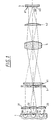
- FIG. 1 shows all array elements only three copies each to make the principle clear to be able to represent.
- An object array 11, 12, 13 is removed from the microtiter plate 1 with wells and substance samples stored therein 110, 120, 130 formed.
- a pinhole 3 arranged which crosstalk between prevents the individual array elements.
- the following telescope from lenses 41 and 42 reduces the Bundle diameter from 130 mm to 15 mm in adaptation to the Dimensions of the CCD array.
- the one in between Field lens 5 ensures the image of the intermediate image and thus of the object array 11, 12, 13 on the elements of the CCD array 6th
- the entire "collective" optics 41, 5, 42 are in theirs Diameter only by the size of the microtiter plate 1 or Item arrays 11, 12, 13 determined.
- one should normal CCD camera with the same numerical aperture of 0.6 have much larger lenses. This is made possible by the fact that the numerical aperture of the optical system according to the invention determined by the elements 21, 22, 23 of the mini lens grid becomes.
- each sample 110, 120, 130 exactly one image zone on the CCD array equivalent.
- FIG. 1 The arrangement of FIG. 1 is already for luminescence measurements immediately suitable, but it will be about ten times as much Focal length of the lens array 21, 22, 23 is preferred, with which recorded sample volume increases.
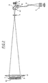
- FIG. 2 is designed as a fluorescence reader. First of all, it has the same elements as FIG. 1, namely Microtiter plate 1 with wells 11i, mini lens array 2i with 96 Lenses, large (41) and small (42) telescopic lenses, in between the field lens 5 and the CCD array 6. Collimated differently but the mini lens array 2i, there is no grid plate, however, a micro lens array 7 immediately in front of the CCD array 6 with 96 microlenses, which are collectively in microstructure technology are produced and the image in the detector cells of the CCD arrays 6 effect.
- the grid size on the CCD array is approximately forty Detector cells with a diameter of about one spot of twenty detector cells in diameter of each Sample element is illuminated.
- a coupling mirror 8 (dichroic mirror) is arranged.
- An illuminating device 9 emits optical fibers 91 and Condenser 92 illuminating light on the mirror 8, which over the already described optical system exactly at the points on the Microtiter plate 1 is directed to the CCD detector 6 be mapped.
- the light of the lighting device 9 is therefore optimally used for the measurement. Interference from Illumination of the structure of the microtiter plate 1 and the like omitted.
- the lighting device can be from a white light source, e.g. a xenon gas discharge lamp, exist, also combined with a monochromator to form a Spectrophotometer.
- a white light source e.g. a xenon gas discharge lamp
- a monochromator e.g. a Spectrophotometer
- a line source e.g. a laser is an option.
- the entire optical arrangement can e.g. a 384-well microtiter plate complete with four positions in a row be read out.
- the beam splitter 8 is not designed and is dichroic A mirror is arranged above the microtiter plate 1, so simply an arrangement for absorption measurement analogous to that device described by Molecular Dynamics become.
- the arrangement is confocal in the sense that one is in the sample spatially limited lighting spot with a spatially limited detection area is superimposed.
- the aperture in Illumination beam path can be the fiber end or a Represent the light field diaphragm, the diaphragm in the Detection beam path can be selected by selectively reading the CCD pixels in the area of the individual lighting spots, by a Pinhole array in front of the CCD camera or through a field diaphragm generated in the field lens.
- Transmitted-light lighting can also use this confocality be realized if an appropriate lens array like that Lens array 2i is provided.
- the focus diameter is better than that Potty diameter (diameter of a well) from 3 to 4 mm adapted for 384 microtiter plates.
- Fluorescence Correlation Spectroscopy can be performed with the parallelized the same optical concept and thus for high-throughput applications become fit.
- FCS Fluorescence Correlation Spectroscopy
Landscapes
- Health & Medical Sciences (AREA)
- Chemical & Material Sciences (AREA)
- Analytical Chemistry (AREA)
- Physics & Mathematics (AREA)
- General Health & Medical Sciences (AREA)
- Pathology (AREA)
- Biochemistry (AREA)
- Life Sciences & Earth Sciences (AREA)
- General Physics & Mathematics (AREA)
- Immunology (AREA)
- Nuclear Medicine, Radiotherapy & Molecular Imaging (AREA)
- Spectroscopy & Molecular Physics (AREA)
- Clinical Laboratory Science (AREA)
- Chemical Kinetics & Catalysis (AREA)
- Hematology (AREA)
- Investigating, Analyzing Materials By Fluorescence Or Luminescence (AREA)
- Spectrometry And Color Measurement (AREA)
- Optical Measuring Cells (AREA)
- Investigating Or Analysing Materials By Optical Means (AREA)
- Microscoopes, Condenser (AREA)
- Devices For Use In Laboratory Experiments (AREA)
- Facsimile Heads (AREA)
Abstract
Claims (8)
- Lecteur pour microplaques de titration ou microplaquettes de substance avec une mosaïque de lentille (21-23) dont la dimension de trame correspond à la dimension de trame d'une microplaque de titration ou d'une microplaquette de substance, un dispositif d'éclairage et une mosaïque de détecteur (61-63), pour lequel une séparation de canal stricte entre les signaux de mesure provenant des volumes d'échantillons individuels de la microplaque de titration ou de la microplaquette de substance est garantie sur la mosaïque de détecteur, caractérisé en ce qu'un télescope est prévu entre la mosaïque de lentille et la mosaïque de détecteur, lequel réduit le diamètre de faisceau défini par la mosaïque de lentille pour l'adapter aux dimensions de la mosaïque de détecteur, en ce qu'une lentille de champ (5) est prévue, en ce que la microplaque de titration ou la microplaquette de substance est représentée de manière réduite sur la mosaïque de détecteur via le système de mosaïque de lentille, télescope et lentille de champ, en ce que le dispositif d'éclairage éclaire exactement ceux des volumes d'échantillons qui sont représentés par la mosaïque de lentille et le télescope sur la mosaïque de détecteur, et en ce que la mosaïque de lentille est achromatisée en ce que chaque lentille individuelle se compose d'un groupe de lentilles à effet achromatique.
- Lecteur selon la revendication 1, caractérisé en ce qu'entre la mosaïque de lentille (21-23) et la lentille de champ (5), et celle-ci et la mosaïque de détecteur (61-63), est aménagée respectivement une lentille (41, 42) du télescope.
- Lecteur selon l'une quelconque des revendications 1-2, caractérisé en ce qu'une mosaïque de microlentille (7) est aménagée devant la mosaïque de détecteur (6).
- Lecteur selon au moins l'une quelconque des revendications 1-3, caractérisé en ce qu'une mosaïque de diaphragme à trou est aménagée entre la mosaïque de lentille (21-23) et la lentille de champ (5).
- Lecteur selon au moins l'une quelconque des revendications 1-4, caractérisé en ce que la mosaïque de détecteur (6) est une mosaïque CCD ou une mosaïque de photodiode.
- Lecteur selon au moins l'une quelconque des revendications 1-5, caractérisé par une construction modulaire avec une mosaïque de lentille (21-23) interchangeable.
- Lecteur selon l'une quelconque des revendications 1-6, caractérisé en ce que la mosaïque de lentille est construite à partir d'un ensemble de petites lentilles conventionnelles aménagées au format 8 * 12 les une par rapport aux autres.
- Lecteur selon l'une quelconque des revendications 1-7, caractérisé en ce qu'un miroir dichroïque (8) est prévu pour la liaison avec le dispositif d'éclairage (9).
Priority Applications (1)
| Application Number | Priority Date | Filing Date | Title |
|---|---|---|---|
| EP03021981A EP1384987A3 (fr) | 1997-10-31 | 1998-10-12 | Lecteur pour microplaques de titration ou chips de substance |
Applications Claiming Priority (3)
| Application Number | Priority Date | Filing Date | Title |
|---|---|---|---|
| DE19748211A DE19748211A1 (de) | 1997-10-31 | 1997-10-31 | Optisches Array-System und Reader für Mikrotiterplatten |
| DE19748211 | 1997-10-31 | ||
| PCT/EP1998/006468 WO1999023474A1 (fr) | 1997-10-31 | 1998-10-12 | Systeme de mosaique optique et lecteur pour microplaques de titration |
Related Child Applications (1)
| Application Number | Title | Priority Date | Filing Date |
|---|---|---|---|
| EP03021981A Division EP1384987A3 (fr) | 1997-10-31 | 1998-10-12 | Lecteur pour microplaques de titration ou chips de substance |
Publications (2)
| Publication Number | Publication Date |
|---|---|
| EP1027591A1 EP1027591A1 (fr) | 2000-08-16 |
| EP1027591B1 true EP1027591B1 (fr) | 2003-12-10 |
Family
ID=7847261
Family Applications (2)
| Application Number | Title | Priority Date | Filing Date |
|---|---|---|---|
| EP98951515A Expired - Lifetime EP1027591B1 (fr) | 1997-10-31 | 1998-10-12 | Systeme de mosaique optique et lecteur pour microplaques de titration |
| EP03021981A Withdrawn EP1384987A3 (fr) | 1997-10-31 | 1998-10-12 | Lecteur pour microplaques de titration ou chips de substance |
Family Applications After (1)
| Application Number | Title | Priority Date | Filing Date |
|---|---|---|---|
| EP03021981A Withdrawn EP1384987A3 (fr) | 1997-10-31 | 1998-10-12 | Lecteur pour microplaques de titration ou chips de substance |
Country Status (7)
| Country | Link |
|---|---|
| US (1) | US6686582B1 (fr) |
| EP (2) | EP1027591B1 (fr) |
| JP (1) | JP4227730B2 (fr) |
| AU (1) | AU9749898A (fr) |
| CA (1) | CA2307837C (fr) |
| DE (2) | DE19748211A1 (fr) |
| WO (1) | WO1999023474A1 (fr) |
Cited By (2)
| Publication number | Priority date | Publication date | Assignee | Title |
|---|---|---|---|---|
| DE102014115564A1 (de) | 2014-10-27 | 2016-04-28 | Christian-Albrechts-Universität Zu Kiel | Mobile photometrische Messvorrichtung und Verfahren zur mobilen photometrischen Messung von Mikrotitierplatten |
| DE102020108432A1 (de) | 2020-03-25 | 2021-09-30 | Jenoptik Optical Systems Gmbh | Vorrichtung und Verfahren zur Lumineszenzanalyse mehrerer Proben |
Families Citing this family (117)
| Publication number | Priority date | Publication date | Assignee | Title |
|---|---|---|---|---|
| CN1664562A (zh) * | 1998-05-16 | 2005-09-07 | 阿普尔拉公司 | 用于监测dna聚合酶链反应的仪器 |
| US7498164B2 (en) | 1998-05-16 | 2009-03-03 | Applied Biosystems, Llc | Instrument for monitoring nucleic acid sequence amplification reaction |
| US6818437B1 (en) | 1998-05-16 | 2004-11-16 | Applera Corporation | Instrument for monitoring polymerase chain reaction of DNA |
| DE19825716A1 (de) | 1998-06-09 | 1999-12-16 | Zeiss Carl Fa | Baugruppe aus optischem Element und Fassung |
| DE19846928A1 (de) | 1998-10-12 | 2000-04-13 | Zeiss Carl Fa | Abbildungssystem mit einem Zylinderlinsenarray |
| EP1131618B1 (fr) * | 1998-11-20 | 2005-10-12 | Graffinity Pharmaceutical Design GmbH | Systeme de mesure et methode pour lecture parallele de detecteurs a resonance plasmonique de surface (spr) |
| GB9906929D0 (en) * | 1999-03-26 | 1999-05-19 | Univ Glasgow | Assay system |
| DE19919092A1 (de) | 1999-04-27 | 2000-11-02 | Zeiss Carl Jena Gmbh | Anordnung zur optischen Auswertung eines Gegenstandsarrays |
| US20050279949A1 (en) * | 1999-05-17 | 2005-12-22 | Applera Corporation | Temperature control for light-emitting diode stabilization |
| US7387891B2 (en) * | 1999-05-17 | 2008-06-17 | Applera Corporation | Optical instrument including excitation source |
| DE19924259C2 (de) * | 1999-05-27 | 2002-11-21 | Fraunhofer Ges Forschung | Vorrichtung und Verfahren zur Erfassung des Füllstandes eines Flüssigkeitsbehälters |
| EP1055925B1 (fr) * | 1999-05-28 | 2010-09-08 | Yokogawa Electric Corporation | Dispositif de lecture de biopuce |
| GB2395267B (en) * | 1999-06-26 | 2004-06-30 | Packard Instrument Co Inc | Improved assay analysis |
| WO2001001112A1 (fr) * | 1999-06-26 | 2001-01-04 | Packard Instrument Company, Inc. | Lecteur pour microplaques |
| DE19930607C2 (de) * | 1999-07-02 | 2002-08-01 | Max Planck Gesellschaft | Verfahren zur Gewinnung von Daten, die Aufschluß geben über die Kinetik der Reaktionen von Reaktanten in einer Vielzahl von Proben und Vorrichtung zur Durchführung des Verfahrens |
| EP1617207A3 (fr) * | 1999-07-21 | 2006-05-31 | Applera Corporation | Station de travail de détection de luminescence |
| EP1221038A4 (fr) * | 1999-07-21 | 2004-09-08 | Applera Corp | Poste de detection de luminescence |
| DE19936999C2 (de) | 1999-08-02 | 2002-03-14 | Jena Optronik Gmbh | Anordnung zum Erfassen der Fluoreszenzstrahlung von matrixförmigen Probenträgern |
| US7217573B1 (en) * | 1999-10-05 | 2007-05-15 | Hitachi, Ltd. | Method of inspecting a DNA chip |
| JP3729043B2 (ja) * | 2000-08-09 | 2005-12-21 | 株式会社日立製作所 | 蛍光画像検出方法並びにdna検査方法及びその装置 |
| US6272939B1 (en) * | 1999-10-15 | 2001-08-14 | Applera Corporation | System and method for filling a substrate with a liquid sample |
| EP1369699A1 (fr) * | 1999-10-15 | 2003-12-10 | PE Corporation (NY) | Système et procédé de remplissage d'un substrat avec un échantillon liquide |
| US6320174B1 (en) * | 1999-11-16 | 2001-11-20 | Ikonisys Inc. | Composing microscope |
| DE10003789C1 (de) * | 2000-01-28 | 2001-08-02 | Werner Freber | Mikroskop |
| US6597522B2 (en) | 2000-01-28 | 2003-07-22 | Werner Freber | Optical system |
| DE10017824B4 (de) * | 2000-04-10 | 2004-03-18 | Till I.D. Gmbh | Vorrichtung zur parallelen photometrischen Fluoreszenz- oder Lumineszenzanalyse mehrerer voneinander getrennter Probenbereiche auf einem Objekt |
| EP1311824A4 (fr) * | 2000-06-25 | 2010-12-08 | Affymetrix Inc | Substrats optiquement actifs |
| US6563581B1 (en) | 2000-07-14 | 2003-05-13 | Applera Corporation | Scanning system and method for scanning a plurality of samples |
| DE10038185C2 (de) | 2000-08-04 | 2003-05-28 | Siemens Ag | Einrichtung zum Erfassen von unterschiedlichen Fluoreszenzsignalen eines mit verschiedenen Anregungswellenlängen ganzflächig beleuchteten Probenträgers |
| DE10153663B4 (de) * | 2000-11-03 | 2005-05-25 | Agilent Technologies, Inc. (n.d.Ges.d.Staates Delaware), Palo Alto | Mikroanalytische Vorrichtung zum Erfassen von Nahe-Infrarot-Strahlung emittierenden Molekülen |
| JP3824135B2 (ja) * | 2001-01-10 | 2006-09-20 | 横河電機株式会社 | バイオチップ読取り装置 |
| WO2002073172A2 (fr) * | 2001-03-09 | 2002-09-19 | Gnothis Holding Sa | Determination d'analytes par spectroscopie de correlation par fluorescence |
| DE10111420A1 (de) * | 2001-03-09 | 2002-09-12 | Gnothis Holding Sa Ecublens | Bestimmung von Analyten durch Fluoreszenz-Korrelationsspektroskopie |
| US20050088735A1 (en) * | 2003-10-22 | 2005-04-28 | Olszak Artur G. | Multi-axis imaging system with single-axis relay |
| US20040004759A1 (en) * | 2002-07-08 | 2004-01-08 | Olszak Artur G. | Microscope array for simultaneously imaging multiple objects |
| US20060291048A1 (en) * | 2001-03-19 | 2006-12-28 | Dmetrix, Inc. | Multi-axis imaging system with single-axis relay |
| WO2002082064A1 (fr) * | 2001-04-06 | 2002-10-17 | Kla-Tencor Corporation | Systeme de detection de defauts ameliore |
| DE10121064A1 (de) * | 2001-04-28 | 2002-10-31 | Evotec Ag | Vorrichtung und Verfahren zur optischen Messung von chemischen und/oder biologischen Proben |
| DE10126083A1 (de) * | 2001-05-29 | 2002-12-05 | Gnothis Holding Sa Ecublens | Verwendung von optischen Diffraktionselementen in Nachweisverfahren |
| US7348587B2 (en) | 2001-06-28 | 2008-03-25 | Fujifilm Corporation | Method for producing biochemical analysis data and apparatus used therefor |
| JP2003057557A (ja) * | 2001-08-09 | 2003-02-26 | Yokogawa Electric Corp | バイオチップ読取装置 |
| DE10145221A1 (de) * | 2001-09-13 | 2003-04-10 | Lavision Biotec Gmbh | Verfahren zur Anregung und Detektion von Fluoreszenzen von Mikroarrays |
| DE10200499A1 (de) * | 2002-01-03 | 2003-07-10 | Zeiss Carl Jena Gmbh | Verfahren und/oder Anordnung zur Identifikation von fluoreszierenden, lumineszierenden und/oder absorbierenden Substanzen auf und/oder in Probenträgern |
| US6982166B2 (en) | 2002-05-16 | 2006-01-03 | Applera Corporation | Lens assembly for biological testing |
| US9157860B2 (en) | 2002-05-16 | 2015-10-13 | Applied Biosystems, Llc | Achromatic lens array |
| US7312432B2 (en) * | 2002-07-08 | 2007-12-25 | Dmetrix, Inc. | Single axis illumination for multi-axis imaging system |
| JP3747890B2 (ja) * | 2002-07-08 | 2006-02-22 | オムロン株式会社 | 光学部品ならびに当該光学部品を用いた光検出装置、光検出方法および分析方法 |
| US20040051030A1 (en) * | 2002-09-17 | 2004-03-18 | Artur Olszak | Method and apparatus for acquiring images from a multiple axis imaging system |
| JP4495083B2 (ja) | 2003-02-13 | 2010-06-30 | 浜松ホトニクス株式会社 | 蛍光相関分光解析装置 |
| US7057720B2 (en) * | 2003-06-24 | 2006-06-06 | Corning Incorporated | Optical interrogation system and method for using same |
| US7292333B2 (en) * | 2003-06-24 | 2007-11-06 | Corning Incorporated | Optical interrogation system and method for 2-D sensor arrays |
| JP2005167824A (ja) * | 2003-12-04 | 2005-06-23 | Canon Inc | 光検出装置及び光空間伝送装置 |
| EP1568986A1 (fr) * | 2004-02-27 | 2005-08-31 | DR. Chip Biotechnology Incorporation | Appareil pour la détection et la reconnaissence d'images des micromatrices |
| US7177023B2 (en) * | 2004-03-19 | 2007-02-13 | Applera Corporation | Fluorescent light detection |
| JP2006058044A (ja) * | 2004-08-18 | 2006-03-02 | Yokogawa Electric Corp | バイオチップ用カートリッジおよびバイオチップ読取装置 |
| WO2006059727A1 (fr) * | 2004-12-03 | 2006-06-08 | National Institute Of Advanced Industrial Science And Technology | Procédé de détection et d’analyse pour matrice de protéine |
| US20060133080A1 (en) * | 2004-12-17 | 2006-06-22 | Bio-Rad Laboratories, Inc., A Corporation Of The State Of Delaware | Multiple light source orientation system for multi-well reaction plate |
| ES2284087T3 (es) | 2005-01-18 | 2007-11-01 | F. Hoffmann-La Roche Ag | Generacion de imagenes de señales de fluorescencia mediante opticas telecentricas de excitacion y de generacion de imagenes. |
| EP1681556B1 (fr) | 2005-01-18 | 2007-04-11 | Roche Diagnostics GmbH | Imagerie de signaux fluorescents en utilisant la télécentricité |
| FI20055043A0 (fi) * | 2005-01-31 | 2005-01-31 | Wallac Oy | Sovitelma mikrotiterkaivojen kuvausjärjestelmässä |
| US20070132831A1 (en) * | 2005-12-13 | 2007-06-14 | Bio-Rad Laboratories, Inc. | Masking to prevent overexposure and light spillage in microarray scanning |
| CA3241457A1 (fr) | 2005-12-21 | 2008-05-15 | Meso Scale Technologies, Llc | Appareils, procedes et reactifs de dosage |
| CN105115949B (zh) * | 2005-12-21 | 2018-06-22 | 梅索斯卡莱科技公司 | 分析装置、方法和试剂 |
| US7995202B2 (en) | 2006-02-13 | 2011-08-09 | Pacific Biosciences Of California, Inc. | Methods and systems for simultaneous real-time monitoring of optical signals from multiple sources |
| US7715001B2 (en) * | 2006-02-13 | 2010-05-11 | Pacific Biosciences Of California, Inc. | Methods and systems for simultaneous real-time monitoring of optical signals from multiple sources |
| US9550185B2 (en) * | 2006-11-09 | 2017-01-24 | Asmag-Holding Gmbh | Titer plate with thin-film-light sensor |
| JP2008175712A (ja) * | 2007-01-19 | 2008-07-31 | Casio Comput Co Ltd | 生体高分子分析チップ |
| DE102007011877A1 (de) * | 2007-03-13 | 2008-09-18 | Eppendorf Ag | Optisches Sensorsystem an einer Vorrichtung zur Behandlung von Flüssigkeiten |
| US20100167413A1 (en) * | 2007-05-10 | 2010-07-01 | Paul Lundquist | Methods and systems for analyzing fluorescent materials with reduced autofluorescence |
| US20080277595A1 (en) * | 2007-05-10 | 2008-11-13 | Pacific Biosciences Of California, Inc. | Highly multiplexed confocal detection systems and methods of using same |
| FI20085062A0 (fi) * | 2008-01-25 | 2008-01-25 | Wallac Oy | Parannettu mittausjärjestelmä ja -menetelmä |
| US20090262332A1 (en) * | 2008-04-18 | 2009-10-22 | Microvast, Inc. | High-throughput spectral imaging and spectroscopy apparatus and methods |
| EP2291643B1 (fr) * | 2008-06-24 | 2016-11-23 | Koninklijke Philips N.V. | Système et procédé de caractérisation de microréseau |
| EP2163885A1 (fr) * | 2008-06-24 | 2010-03-17 | Koninklijke Philips Electronics N.V. | Système et procédé de caractérisation de microréseau |
| EP2148187A1 (fr) * | 2008-07-25 | 2010-01-27 | Roche Diagnostics GmbH | Optique d'excitation et de représentation pour la détection de fluorescence |
| WO2010110096A1 (fr) * | 2009-03-26 | 2010-09-30 | ユニバーサル・バイオ・リサーチ株式会社 | Dispositif réactionnel de mesure optique et son procédé de mesure |
| US8530243B2 (en) | 2009-04-20 | 2013-09-10 | Bio-Rad Laboratories Inc. | Non-scanning SPR system |
| CN101581829B (zh) * | 2009-06-19 | 2011-11-09 | 宁波永新光学股份有限公司 | 一种基于微透镜阵列的cmos传感器的显微镜成像方法及系统 |
| JP2011158419A (ja) * | 2010-02-03 | 2011-08-18 | Sony Corp | 光学検出装置 |
| DE102010001714A1 (de) | 2010-02-09 | 2011-08-11 | Robert Bosch GmbH, 70469 | Vorrichtung und Verfahren zur optischen Parallelanalyse einer Probenanordnung und entsprechendes Herstellungsverfahren |
| JP5609611B2 (ja) * | 2010-03-11 | 2014-10-22 | 株式会社リコー | 分光特性取得装置、画像評価装置、及び画像形成装置 |
| DE102010016382B4 (de) * | 2010-04-09 | 2022-06-02 | Leica Microsystems Cms Gmbh | Fluoreszenzmikroskop und Verfahren zur Durchführung von Multipositionierungen in einer Screening-Applikation |
| US8611004B2 (en) | 2010-06-10 | 2013-12-17 | Spaario Inc. | Optical system providing magnification |
| DE102010023486A1 (de) * | 2010-06-11 | 2011-12-15 | B. Braun Avitum Ag | Nachweisvorrichtung und -verfahren |
| JP5644296B2 (ja) * | 2010-09-13 | 2014-12-24 | 株式会社リコー | 分光特性取得装置、画像評価装置、及び画像形成装置 |
| DE102010049212A1 (de) * | 2010-10-21 | 2012-04-26 | Rudolf Grosskopf | Simultane Fluoreszenzkorrelationsspektroskopie (sFCS) |
| CN103782155B (zh) * | 2011-09-06 | 2016-11-16 | 皇家飞利浦有限公司 | 具有多个传感器区域的光学生物传感器 |
| DE202012104237U1 (de) * | 2011-11-04 | 2013-05-22 | Dynex Technologies Inc. | Multiplex-Optikanordnung |
| WO2013186780A1 (fr) | 2012-06-13 | 2013-12-19 | Hadasit Medical Research Services And Development Ltd. | Dispositifs et procédés de détection de saignement interne et d'hématome |
| TW201400607A (en) * | 2012-06-22 | 2014-01-01 | Maestrogen Inc | Assistant pipetting device for microtiter plate |
| US20150018642A1 (en) * | 2013-07-12 | 2015-01-15 | Sandeep Gulati | Tissue pathlength resolved noninvasive analyzer apparatus and method of use thereof |
| US9506865B2 (en) * | 2012-08-02 | 2016-11-29 | Roche Molecular Systems, Inc. | Array optics |
| US8790599B2 (en) | 2012-08-13 | 2014-07-29 | David Childs | Microtiter plate system and method |
| CN102818886A (zh) * | 2012-08-28 | 2012-12-12 | 天津市先石光学技术有限公司 | 一种小剂量均相激发光免疫检测仪 |
| DE102012018303A1 (de) * | 2012-09-14 | 2014-03-20 | Fraunhofer-Gesellschaft zur Förderung der angewandten Forschung e.V. | Messgerät zur Lumineszenzmessung |
| US10036877B2 (en) | 2013-02-05 | 2018-07-31 | Vanderbilt University | Microlens array for enhanced imaging of multiregion targets |
| KR101568573B1 (ko) * | 2013-03-13 | 2015-11-20 | 고려대학교 산학협력단 | 혈중 희소 세포의 검출 및 계수 장치와 방법 |
| KR102452571B1 (ko) | 2014-08-08 | 2022-10-07 | 퀀텀-에스아이 인코포레이티드 | 수신된 광자들의 시간 비닝을 위한 집적 디바이스 |
| CA2988822C (fr) * | 2015-01-30 | 2022-06-28 | Japan Science And Technology Agency | Appareil de mesure spectrometrique multifocal et systeme optique destine a un appareil de mesure spectrometrique multifocal |
| US9475149B1 (en) | 2015-04-24 | 2016-10-25 | Testrake Aviation, Inc. | Optical device and method of making same |
| WO2017018014A1 (fr) * | 2015-07-28 | 2017-02-02 | 株式会社ダナフォーム | Kit d'analyse et procédé d'analyse l'utilisant |
| JP6345169B2 (ja) * | 2015-12-24 | 2018-06-20 | 株式会社Screenホールディングス | レンズユニット、ウエルプレート、画像取得装置 |
| CA3012705A1 (fr) | 2016-02-17 | 2017-08-24 | Tesseract Health, Inc. | Capteur et dispositif pour applications d'imagerie et de detection de duree de vie |
| CN118099177A (zh) | 2016-12-22 | 2024-05-28 | 宽腾矽公司 | 具有直接合并像素的整合式光电侦测器 |
| JP2020509391A (ja) | 2017-01-10 | 2020-03-26 | フォトスイッチ・バイオサイエンシズ・インコーポレイテッド | 検出のためのシステムおよび方法 |
| JP6439810B2 (ja) * | 2017-02-06 | 2018-12-19 | 横河電機株式会社 | バイオチップ、バイオチップユニット、バイオチップ読取装置、及びバイオチップ製造方法 |
| JP6731901B2 (ja) * | 2017-09-29 | 2020-07-29 | 株式会社日立ハイテク | 分析装置 |
| JP7460555B2 (ja) | 2018-06-22 | 2024-04-02 | クアンタム-エスアイ インコーポレイテッド | 様々な検出時間の電荷貯蔵ビンを有する集積光検出器 |
| US20200072752A1 (en) * | 2018-08-29 | 2020-03-05 | Quantum-Si Incorporated | System and methods for detecting lifetime using photon counting photodetectors |
| US11333748B2 (en) | 2018-09-17 | 2022-05-17 | Waymo Llc | Array of light detectors with corresponding array of optical elements |
| KR102292599B1 (ko) * | 2019-11-06 | 2021-08-23 | 주식회사 뷰웍스 | 광학 분석 장치 및 광학 분석 방법 |
| AU2021208557A1 (en) | 2020-01-14 | 2022-09-01 | Quantum-Si Incorporated | Sensor for lifetime plus spectral characterization |
| TW202143465A (zh) | 2020-01-14 | 2021-11-16 | 美商寬騰矽公司 | 用於壽命特性分析之整合感應器 |
| KR20220148273A (ko) | 2020-03-02 | 2022-11-04 | 퀀텀-에스아이 인코포레이티드 | 다차원 신호 분석을 위한 통합 센서 |
| WO2021207400A2 (fr) | 2020-04-08 | 2021-10-14 | Quantum-Si Incorporated | Capteur intégré à inclinaison réduite |
| US11619588B2 (en) * | 2020-10-26 | 2023-04-04 | K2R2 Llc | Portable analyzer |
| US20240027655A1 (en) * | 2022-07-19 | 2024-01-25 | Trustees Of Boston University | High throughput screening system for engineered cardiac tissues |
Family Cites Families (14)
| Publication number | Priority date | Publication date | Assignee | Title |
|---|---|---|---|---|
| DE2718896C3 (de) * | 1977-04-28 | 1988-09-29 | Fa. Carl Zeiss, 7920 Heidenheim | Achromatisches Mikroskopobjektiv aus drei Linsengliedern |
| US4710031A (en) * | 1985-07-31 | 1987-12-01 | Lancraft, Inc. | Microtiter plate reader |
| US5355215A (en) * | 1992-09-30 | 1994-10-11 | Environmental Research Institute Of Michigan | Method and apparatus for quantitative fluorescence measurements |
| WO1995001599A1 (fr) * | 1993-07-01 | 1995-01-12 | Legent Corporation | Systeme et procede de gestion de memoire repartie sur des systemes informatiques en reseau |
| WO1995001559A2 (fr) * | 1993-07-02 | 1995-01-12 | Evotec Biosystems Gmbh | Porte-echantillons et son utilisation |
| CA2129787A1 (fr) * | 1993-08-27 | 1995-02-28 | Russell G. Higuchi | Surveillance de plusieurs reactions d'amplification simultanement et analyse de ces reactions simultanement |
| JP3404607B2 (ja) * | 1993-09-30 | 2003-05-12 | 株式会社小松製作所 | 共焦点光学装置 |
| US5659420A (en) * | 1993-09-30 | 1997-08-19 | Kabushiki Kaisha Komatsu Seisakusho | Confocal optical apparatus |
| FI98765C (fi) * | 1995-01-16 | 1997-08-11 | Erkki Soini | Virtaussytometrinen menetelmä ja laite |
| DE19624421B4 (de) * | 1995-06-30 | 2008-07-10 | Carl Zeiss Ag | Vorrichtung und Verfahren zur ortsaufgelösten Vermessung von Wellenfrontdeformationen |
| JP3350918B2 (ja) * | 1996-03-26 | 2002-11-25 | 株式会社高岳製作所 | 2次元配列型共焦点光学装置 |
| JP3152140B2 (ja) * | 1995-12-18 | 2001-04-03 | 横河電機株式会社 | 共焦点用光スキャナ |
| JP2001500628A (ja) * | 1996-02-28 | 2001-01-16 | ケニス シー ジョンソン | マイクロリトグラフィ用マイクロレンズスキャナ及び広フィールド共焦顕微鏡 |
| DE19651667C2 (de) * | 1996-12-12 | 2003-07-03 | Rudolf Groskopf | Vorrichtung zur dreidimensionalen Untersuchung eines Objektes |
-
1997
- 1997-10-31 DE DE19748211A patent/DE19748211A1/de not_active Withdrawn
-
1998
- 1998-10-12 EP EP98951515A patent/EP1027591B1/fr not_active Expired - Lifetime
- 1998-10-12 DE DE59810420T patent/DE59810420D1/de not_active Expired - Lifetime
- 1998-10-12 WO PCT/EP1998/006468 patent/WO1999023474A1/fr active IP Right Grant
- 1998-10-12 JP JP2000519289A patent/JP4227730B2/ja not_active Expired - Fee Related
- 1998-10-12 AU AU97498/98A patent/AU9749898A/en not_active Abandoned
- 1998-10-12 CA CA2307837A patent/CA2307837C/fr not_active Expired - Fee Related
- 1998-10-12 EP EP03021981A patent/EP1384987A3/fr not_active Withdrawn
- 1998-10-12 US US09/530,612 patent/US6686582B1/en not_active Expired - Fee Related
Cited By (4)
| Publication number | Priority date | Publication date | Assignee | Title |
|---|---|---|---|---|
| DE102014115564A1 (de) | 2014-10-27 | 2016-04-28 | Christian-Albrechts-Universität Zu Kiel | Mobile photometrische Messvorrichtung und Verfahren zur mobilen photometrischen Messung von Mikrotitierplatten |
| WO2016066156A2 (fr) | 2014-10-27 | 2016-05-06 | Christian-Albrechts-Universität Zu Kiel | Dispositif de mesure photométrique mobile et procédé de mesure photométrique mobile sur des plaques de microtitrage |
| DE102020108432A1 (de) | 2020-03-25 | 2021-09-30 | Jenoptik Optical Systems Gmbh | Vorrichtung und Verfahren zur Lumineszenzanalyse mehrerer Proben |
| WO2021190991A1 (fr) | 2020-03-25 | 2021-09-30 | Jenoptik Optical Systems Gmbh | Dispositif et procédé d'analyse de luminescence de multiples échantillons |
Also Published As
| Publication number | Publication date |
|---|---|
| CA2307837C (fr) | 2010-04-13 |
| WO1999023474A1 (fr) | 1999-05-14 |
| EP1027591A1 (fr) | 2000-08-16 |
| CA2307837A1 (fr) | 1999-05-14 |
| EP1384987A2 (fr) | 2004-01-28 |
| US6686582B1 (en) | 2004-02-03 |
| DE59810420D1 (de) | 2004-01-22 |
| JP2002514739A (ja) | 2002-05-21 |
| EP1384987A3 (fr) | 2012-10-03 |
| AU9749898A (en) | 1999-05-24 |
| DE19748211A1 (de) | 1999-05-06 |
| JP4227730B2 (ja) | 2009-02-18 |
Similar Documents
| Publication | Publication Date | Title |
|---|---|---|
| EP1027591B1 (fr) | Systeme de mosaique optique et lecteur pour microplaques de titration | |
| EP1121581B1 (fr) | Systeme d'imagerie comportant un ensemble de lentilles cylindriques | |
| DE10004191B4 (de) | Fluoreszenz-Scanmikroskop | |
| DE602005000877T2 (de) | Fluoreszenzabbildung mittels Telezentrizität | |
| EP3526634B1 (fr) | Groupe optique pour une lumière de détection pour un microscope, procédé de microscopie et microscope | |
| DE19914279C1 (de) | Anordnung zum optischen Auslesen der Information von einem matrixförmigen Substrat mit einer Vielzahl von Einzelproben | |
| EP2860567B1 (fr) | Microscopie à balayage haute résolution | |
| EP0762114A2 (fr) | Appareil de spectroscopie de corrélation à deux photons pour mesurer en parallèle plusieurs échantillons et son application au screening d'une substance active | |
| EP0898783A2 (fr) | Microscope a balayage dans lequel un echantillon est excite optiquement simultanement en plusieurs points | |
| WO2000065325A2 (fr) | Dispositif pour l'evaluation optique d'un ensemble d'objets | |
| EP0736767A1 (fr) | Dispositif de détection optique pour des mesures analytiques de substances chimiques | |
| EP1128200A2 (fr) | Structure de microscope | |
| EP1678547B1 (fr) | Dispositif et procede de mesure des proprietes optiques d'un objet | |
| DE19936999C2 (de) | Anordnung zum Erfassen der Fluoreszenzstrahlung von matrixförmigen Probenträgern | |
| WO1999039191A1 (fr) | Dispositif et procede d'electrophorese capillaire | |
| DE60117703T2 (de) | Lumineszenz-abbildungsvorrichtung | |
| DE102020212029A1 (de) | Vorrichtung und Verfahren zur simultanen Abbildung zweier Objektebenen | |
| DE10017824B4 (de) | Vorrichtung zur parallelen photometrischen Fluoreszenz- oder Lumineszenzanalyse mehrerer voneinander getrennter Probenbereiche auf einem Objekt | |
| EP0961930B1 (fr) | Dispositif de balayage lumineux | |
| DE10024132B4 (de) | Anordnung zur Detektion von Fluoreszenzlicht mehrerer Probenpunkte | |
| DE10206004A1 (de) | Vorrichtung zur konfokalen optischen Mikroanalyse | |
| WO2003042671A1 (fr) | Systeme d'imagerie en fond noir destine a l'imagerie en fond noir a resolution spatiale d'un echantillon et methode d'examen | |
| DE102019110869A1 (de) | Mikroskop | |
| DE10131684C1 (de) | Vorrichtung und Verfahren zur ortsaufgelösten Messung einer Schichtdicke | |
| DE3635684A1 (de) | Multispektrallampenanordnung |
Legal Events
| Date | Code | Title | Description |
|---|---|---|---|
| PUAI | Public reference made under article 153(3) epc to a published international application that has entered the european phase |
Free format text: ORIGINAL CODE: 0009012 |
|
| 17P | Request for examination filed |
Effective date: 20000405 |
|
| AK | Designated contracting states |
Kind code of ref document: A1 Designated state(s): CH DE FR GB LI SE |
|
| 17Q | First examination report despatched |
Effective date: 20020502 |
|
| GRAH | Despatch of communication of intention to grant a patent |
Free format text: ORIGINAL CODE: EPIDOS IGRA |
|
| GRAS | Grant fee paid |
Free format text: ORIGINAL CODE: EPIDOSNIGR3 |
|
| GRAA | (expected) grant |
Free format text: ORIGINAL CODE: 0009210 |
|
| AK | Designated contracting states |
Kind code of ref document: B1 Designated state(s): CH DE FR GB LI SE |
|
| REG | Reference to a national code |
Ref country code: GB Ref legal event code: FG4D Free format text: NOT ENGLISH |
|
| REG | Reference to a national code |
Ref country code: CH Ref legal event code: EP |
|
| REF | Corresponds to: |
Ref document number: 59810420 Country of ref document: DE Date of ref document: 20040122 Kind code of ref document: P |
|
| PG25 | Lapsed in a contracting state [announced via postgrant information from national office to epo] |
Ref country code: SE Free format text: LAPSE BECAUSE OF FAILURE TO SUBMIT A TRANSLATION OF THE DESCRIPTION OR TO PAY THE FEE WITHIN THE PRESCRIBED TIME-LIMIT Effective date: 20040310 |
|
| GBT | Gb: translation of ep patent filed (gb section 77(6)(a)/1977) |
Effective date: 20040303 |
|
| RAP2 | Party data changed (patent owner data changed or rights of a patent transferred) |
Owner name: CARL-ZEISS-STIFTUNG TRADING AS CARL ZEISS Owner name: CARL ZEISS |
|
| ET | Fr: translation filed | ||
| PLBE | No opposition filed within time limit |
Free format text: ORIGINAL CODE: 0009261 |
|
| STAA | Information on the status of an ep patent application or granted ep patent |
Free format text: STATUS: NO OPPOSITION FILED WITHIN TIME LIMIT |
|
| 26N | No opposition filed |
Effective date: 20040913 |
|
| PGFP | Annual fee paid to national office [announced via postgrant information from national office to epo] |
Ref country code: DE Payment date: 20121023 Year of fee payment: 15 Ref country code: CH Payment date: 20121023 Year of fee payment: 15 Ref country code: FR Payment date: 20121031 Year of fee payment: 15 |
|
| PGFP | Annual fee paid to national office [announced via postgrant information from national office to epo] |
Ref country code: GB Payment date: 20121019 Year of fee payment: 15 |
|
| REG | Reference to a national code |
Ref country code: DE Ref legal event code: R081 Ref document number: 59810420 Country of ref document: DE Owner name: CARL ZEISS MICROSCOPY GMBH, DE Free format text: FORMER OWNER: CARL ZEISS, 89518 HEIDENHEIM, DE Effective date: 20130108 |
|
| REG | Reference to a national code |
Ref country code: CH Ref legal event code: PL |
|
| GBPC | Gb: european patent ceased through non-payment of renewal fee |
Effective date: 20131012 |
|
| REG | Reference to a national code |
Ref country code: DE Ref legal event code: R119 Ref document number: 59810420 Country of ref document: DE Effective date: 20140501 |
|
| PG25 | Lapsed in a contracting state [announced via postgrant information from national office to epo] |
Ref country code: CH Free format text: LAPSE BECAUSE OF NON-PAYMENT OF DUE FEES Effective date: 20131031 Ref country code: LI Free format text: LAPSE BECAUSE OF NON-PAYMENT OF DUE FEES Effective date: 20131031 Ref country code: GB Free format text: LAPSE BECAUSE OF NON-PAYMENT OF DUE FEES Effective date: 20131012 |
|
| REG | Reference to a national code |
Ref country code: FR Ref legal event code: ST Effective date: 20140630 |
|
| PG25 | Lapsed in a contracting state [announced via postgrant information from national office to epo] |
Ref country code: FR Free format text: LAPSE BECAUSE OF NON-PAYMENT OF DUE FEES Effective date: 20131031 Ref country code: DE Free format text: LAPSE BECAUSE OF NON-PAYMENT OF DUE FEES Effective date: 20140501 |