EP1022244A2 - Anlegetisch - Google Patents
Anlegetisch Download PDFInfo
- Publication number
- EP1022244A2 EP1022244A2 EP00100387A EP00100387A EP1022244A2 EP 1022244 A2 EP1022244 A2 EP 1022244A2 EP 00100387 A EP00100387 A EP 00100387A EP 00100387 A EP00100387 A EP 00100387A EP 1022244 A2 EP1022244 A2 EP 1022244A2
- Authority
- EP
- European Patent Office
- Prior art keywords
- feed
- feed table
- plane
- sheets
- deflection
- Prior art date
- Legal status (The legal status is an assumption and is not a legal conclusion. Google has not performed a legal analysis and makes no representation as to the accuracy of the status listed.)
- Granted
Links
Images
Classifications
-
- B—PERFORMING OPERATIONS; TRANSPORTING
- B65—CONVEYING; PACKING; STORING; HANDLING THIN OR FILAMENTARY MATERIAL
- B65H—HANDLING THIN OR FILAMENTARY MATERIAL, e.g. SHEETS, WEBS, CABLES
- B65H11/00—Feed tables
- B65H11/002—Feed tables incorporating transport belts
-
- B—PERFORMING OPERATIONS; TRANSPORTING
- B65—CONVEYING; PACKING; STORING; HANDLING THIN OR FILAMENTARY MATERIAL
- B65H—HANDLING THIN OR FILAMENTARY MATERIAL, e.g. SHEETS, WEBS, CABLES
- B65H5/00—Feeding articles separated from piles; Feeding articles to machines
- B65H5/36—Article guides or smoothers, e.g. movable in operation
- B65H5/38—Article guides or smoothers, e.g. movable in operation immovable in operation
-
- B—PERFORMING OPERATIONS; TRANSPORTING
- B65—CONVEYING; PACKING; STORING; HANDLING THIN OR FILAMENTARY MATERIAL
- B65H—HANDLING THIN OR FILAMENTARY MATERIAL, e.g. SHEETS, WEBS, CABLES
- B65H2301/00—Handling processes for sheets or webs
- B65H2301/40—Type of handling process
- B65H2301/44—Moving, forwarding, guiding material
- B65H2301/443—Moving, forwarding, guiding material by acting on surface of handled material
- B65H2301/4431—Moving, forwarding, guiding material by acting on surface of handled material by means with operating surfaces contacting opposite faces of material
- B65H2301/44312—Moving, forwarding, guiding material by acting on surface of handled material by means with operating surfaces contacting opposite faces of material between belts and rollers
Definitions
- the innovation concerns a feed table for the application of sheets to one sheet processing machine, especially a printing machine, the sheet can be fed from a sheet feeder in an approximately horizontal feed plane and which is inclined with respect to the feed plane, being approximately over the area a deflection roller at the kink between the feed level and the feed table is arranged through the sheet from the feed plane into the plane of the Feed tables are deflectable.
- the task of the innovation is therefore a feed table of the type mentioned
- a wide variety of arches, especially for arches with high rigidity is suitable and safely deflects all bends as well as the feed table to exact further transport.
- this object is achieved in that several deflection rollers are provided.
- the deflection rollers are spaced perpendicularly to the plane of the feed table and are adjustable, and are arranged in the form of a curve that runs approximately tangentially against the plane of the feed table.
- the deflection rollers used in the arrangement are freely rotatable, so that there are no grinding marks on the sheet due to a deflection roller.
- a simple design is achieved in that the deflecting roller is designed as a relatively narrow deflecting wheel and is arranged on the free end of a height-adjustable holder.
- a guiding of the sheets over a longer section is achieved and a rocking of the rear end of the sheet is largely avoided if the deflection wheels are arranged one behind the other in the conveying direction, with preferably all deflection wheels being freely rotatable. If the deflection wheels are arranged at a distance from one another and are mutually rotatably mounted on the holder as a common support, the contours of the deflection wheels overlapping one another, a secure contact of each sheet on all deflection wheels can thus be ensured, so that each sheet is securely placed on the feed table or on a conveyor belt guided over the feed table. For safe deflection of the sheets, it is used if several holders with deflection wheels are arranged next to one another transversely to the conveying direction.
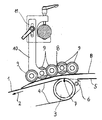
- the feed table shown in the figure has a table surface 1, at the ends of which are arranged in the conveying direction 2, belt rollers 3, over which endless conveyor belts 4 are guided.
- the conveyor belts 4 can be driven by one of the belt rollers 3 and transport sheets in the conveying direction 2 to a printing press.
- the sheets B at the higher end of the inclined feed table are fed approximately horizontally above the surface forming a feed plane 5 from a sheet stack of a sheet feeder.
- Tiltable stops 6 can be provided on the feed side, which are only indicated here. These stops 6 release the sheet path from the sheet stack to the belt roll 3.
- the forward movement of the sheet to the feed table is brought about by conveyor rollers (not shown here) which can be adjusted cyclically on the belt roller.
- the sheet B is clamped between the belt roller 3 and the conveyor rollers and moved forward by the rotation of the belt roller 3.
- the conveyor rollers only act selectively on the belt roller 3.
- an additional conveyor roller can Belt roller 3 can be arranged. Then the conveyor rollers work with this Conveyor roller together. The sheets B are then at the higher end of the inclined feed table from the sheet feeder over a Bridging level of the belt roll 3 fed. The bridging level then forms the feed plane 5, which is important in the invention.
- the transfer rollers 8 consist of a common carrier 10 which is attached to a height-adjustable holder 11 is attached.
- the transfer rollers 8 also have a number of deflection wheels 9 on which are mutually attached to the carrier 10.
- the center distance of the Deflection wheels 9 is selected so that the contours of the deflection wheels 9 somewhat cover up. This creates a quasi on the underside of the transfer rollers 8 continuous guiding surface.
- the deflection wheels 9 are on the carrier 10 in the direction the connection of their axes of rotation arranged approximately in an arc.
- the conductivity of the transfer rollers 8 can be seen from the drawing. It is recognizable that the sheet B from the transfer rollers 8 from the horizontal to a oblique conveying direction is curved.
- the sheet B lies on the Conveyor belts 4. In a preferred embodiment, these are with their Suction tapes on the underside, which hold the sheet in contact capture and hold on with a small area.
- the representation of the position of the sheet to be guided from the figure can also for the embodiment described above with an upstream conveyor roller be accepted. Stiffer bends are also deflected safely and so directed to the suction tapes that they can grasp the sheets.
- Conveyor rollers are the transfer rollers 8 closer to the surface of the Feed table set. Then the conductivity of the transfer rollers 8 sets in essentially immediately after the sheet B emerges between the conveyor rollers and the belt roller 3.
Landscapes
- Engineering & Computer Science (AREA)
- Mechanical Engineering (AREA)
- Delivering By Means Of Belts And Rollers (AREA)
- Sheets, Magazines, And Separation Thereof (AREA)
- Registering Or Overturning Sheets (AREA)
- Electrical Discharge Machining, Electrochemical Machining, And Combined Machining (AREA)
- Valve Device For Special Equipments (AREA)
- Feeding Of Articles By Means Other Than Belts Or Rollers (AREA)
Abstract
Description
Vorzugsweise sind die in der Anordnung verwendeten Umlenkrollen frei drehbar gelagert, so daß es durch eine Umlenkrolle nicht zu Schleifspuren auf den Bogen kommen kann.
Eine einfache Ausbildung wird dadurch erreicht, daß die Umlenkrolle als relativ schmale Umlenkräder ausgebildet sind und an dem freien Ende eines in der Höhe einstellbaren Halters angeordnet ist.
Sind die Umlenkräder in einem Abstand zueinander angeordnet und wechselseitig an dem Halter als gemeinsamen Träger drehbar gelagert, wobei die Konturen der Umlenkräder einander überlappen, kann damit eine sichere Anlage jedes Bogens an allen Umlenkrädern gewährleistet werden, so daß jeder Bogen sicher auf dem Anlegetisch bzw. auf ein über den Anlegetisch geführtes Förderband geführt wird. Zum sicheren Umlenken der Bogen dient es, wenn quer zur Förderrichtung im Abstand nebeneinander mehrere Halter mit Umlenkrädern angeordnet sind.
Die Bogen B am höher liegenden Ende des geneigt angeordneten Anlegetischs werden etwa horizontal oberhalb der eine Zuführebene 5 bildenden Oberfläche von einem Bogenstapel eines Bogenanlegers zugeführt. An der Zufuhrseite können kippbare Anschläge 6 vorgesehen sein, die hier nur angedeutet sind. Diese Anschläge 6 geben den Bogenweg vom Bogenstapel zur Bänderwalze 3 frei. Die Vorwärtsbewegung des Bogens zum Anlegetisch wird durch hier nicht gezeigte, auf die Bänderwalze taktweise anstellbare Förderrollen bewirkt bewirkt. Der Bogen B wird zwischen der Bänderwalze 3 und den Förderrollen eingeklemmt und durch die Drehung der Bänderwalze 3 vorwärts bewegt. Die Förderrollen wirken aber nur punktuell an der Bänderwalze 3.
- 1
- Tischoberfläche
- 2
- Förderrichtung
- 3
- Bänderwalze
- 4
- Förderband
- 5
- Zuführebene
- 6
- Förderwalze
- 7
- Knickstelle
- 8
- Überleitrollen
- 9
- Umlenkrad
- 10
- Träger
- 11
- Halterung
Claims (7)
- Anlegetisch zum Anlegen von Bogen an eine bogenverarbeitende Maschine, insbesondere eine Druckmaschine, dem Bogen von einem Bogenanleger in einer etwa horizontalen Zuführebene zuführbar sind und der gegenüber der Zuführebene geneigt ist, wobei etwa über dem Bereich der Knickstelle zwischen Zuführebene und Anlegetisch wenigstens eine Umlenkrolle angeordnet ist, durch die die Bogen aus der Zuführebene in die Ebene des Anlegetischs umlenkbar sind,
dadurch gekennzeichnet,
daß mehrere Umlenkrollen derart angeordnet sind, daß sie eine im wesentlichen gekrümmte Leitebene bilden, die mit einem von der Dicke der Bogen (B) abhängigen Mindestabstand jeweils etwa tangential zur horizontalen Zuführebene (5) und zu einer Tischoberfläche (1) des Anlegetisches ausläuft. - Anlegetisch nach Anspruch 1,
dadurch gekennzeichnet,
daß die Umlenkrollen frei drehbar gelagert sind. - Anlegetisch nach einem der vorhergehenden Ansprüche,
dadurch gekennzeichnet,
daß die Umlenkrollen als Umlenkräder (9) ausgebildet sind und daß die Umlenkräder (9) in Förderrichtung (2) der Bogen (B) hintereinander an einem Ende eines Halters (8, 10) angeordnet sind. - Anlegetisch nach Anspruch 3,
dadurch gekennzeichnet,
daß die Umlenkräder (9) wechselseitig an dem Halter (8, 10) befestigt und derart angeordnet sind, daß die Konturen jeweils zweier gegenüberliegender Umlenkräder (9) sich überschneiden. - Anlegetisch nach einem der vorhergehenden Ansprüche,
dadurch gekennzeichnet,
daß der Halter (8, 10) als starres Element ausgebildet und so angeordnet ist, daß eine tangential zu den Umlenkrädern (9) gegenüber der Tischoberfläche (1) bzw. der Zuführebene (5) verlaufende Leitebene in ihrer Ausrichtung zur Förderebene der Bogen (B) einstellbar sind. - Anlegetisch nach Anspruch 5,
dadurch gekennzeichnet,
daß der Halter (8, 10) als starres Element ausgebildet und so angeordnet ist, daß die Umlenkräder (9) in ihrem Abstand zur Förderebene der Bogen (B) einstellbar sind. - Anlegetisch nach einem der vorhergehenden Ansprüche,
dadurch gekennzeichnet,
daß quer zur Förderrichtung (2) im Abstand nebeneinander mehrere Halter (8, 10) mit Umlenkrädern (9) angeordnet sind.
Applications Claiming Priority (2)
| Application Number | Priority Date | Filing Date | Title |
|---|---|---|---|
| DE29900995U DE29900995U1 (de) | 1999-01-21 | 1999-01-21 | Anlegetisch |
| DE29900995U | 1999-01-21 |
Publications (3)
| Publication Number | Publication Date |
|---|---|
| EP1022244A2 true EP1022244A2 (de) | 2000-07-26 |
| EP1022244A3 EP1022244A3 (de) | 2001-05-23 |
| EP1022244B1 EP1022244B1 (de) | 2003-08-06 |
Family
ID=8068280
Family Applications (1)
| Application Number | Title | Priority Date | Filing Date |
|---|---|---|---|
| EP00100387A Expired - Lifetime EP1022244B1 (de) | 1999-01-21 | 2000-01-08 | Anlegetisch |
Country Status (6)
| Country | Link |
|---|---|
| US (1) | US6290222B1 (de) |
| EP (1) | EP1022244B1 (de) |
| JP (1) | JP2000219349A (de) |
| AT (1) | ATE246656T1 (de) |
| DE (2) | DE29900995U1 (de) |
| ES (1) | ES2204364T3 (de) |
Cited By (2)
| Publication number | Priority date | Publication date | Assignee | Title |
|---|---|---|---|---|
| EP1256448A3 (de) * | 2001-05-07 | 2004-03-31 | LTG Mailänder GmbH | Bogenführung für eine Bogen verarbeitende Maschine sowie Verfahren zur Führung eines Bogens |
| DE102010005189A1 (de) | 2010-01-21 | 2011-07-28 | Dr. Ing. h.c. F. Porsche Aktiengesellschaft, 70435 | Kraftfahrzeug mit einer Radhausverkleidung |
Families Citing this family (6)
| Publication number | Priority date | Publication date | Assignee | Title |
|---|---|---|---|---|
| DE20008412U1 (de) | 2000-05-10 | 2000-08-17 | MAN Roland Druckmaschinen AG, 63075 Offenbach | Anlegetisch |
| DE10129007C1 (de) * | 2001-06-15 | 2002-10-17 | Roland Man Druckmasch | Vorrichtung zum unterschuppten Zuführen von Bogen |
| US20040094360A1 (en) * | 2002-11-06 | 2004-05-20 | Calsonic Kansei Corporation | Acoustic dumper for exhaust system |
| JP4595928B2 (ja) * | 2006-11-27 | 2010-12-08 | パナソニック株式会社 | 印刷用記録プレート供給装置 |
| JP5958097B2 (ja) * | 2012-06-05 | 2016-07-27 | 富士ゼロックス株式会社 | シート搬送装置、画像形成装置 |
| JP5627759B2 (ja) * | 2013-12-16 | 2014-11-19 | キヤノン株式会社 | シート搬送装置、画像形成装置及び画像読取装置 |
Family Cites Families (8)
| Publication number | Priority date | Publication date | Assignee | Title |
|---|---|---|---|---|
| DE196460C (de) * | ||||
| US843709A (en) * | 1906-02-05 | 1907-02-12 | American Laundry Mach Co | Feeding attachment for mangles. |
| DE2261416C3 (de) * | 1972-12-15 | 1975-12-18 | Jagenberg-Werke Ag, 4000 Duesseldorf | Vorrichtung zum Einbringen von Faltschachtelzuschnitten od. dgl. in Versandkartons |
| DE2552998C2 (de) * | 1975-11-26 | 1983-11-10 | Heidelberger Druckmaschinen Ag, 6900 Heidelberg | Bogenausleger für Rotationsdruckmaschinen |
| NL9000309A (nl) * | 1990-02-09 | 1991-09-02 | Hadewe Bv | Werkwijze en inrichting voor het vanaf een stapel stuksgewijs afgeven van platte voorwerpen. |
| GB9306009D0 (en) * | 1993-03-23 | 1993-05-12 | Ncr Int Inc | Sheet handing apparatus |
| DE29710296U1 (de) | 1997-06-12 | 1998-10-15 | Hagestedt, Veronika, 27777 Ganderkesee | Schablone zur Herstellung von dekorativen, aufliegenden Ornamenten, insbesondere auf Wand- und Deckenflächen |
| EP0893383A3 (de) * | 1997-07-16 | 1999-05-19 | Grapha-Holding Ag | Vorrichtung zum Transport von Druckereiprodukten |
-
1999
- 1999-01-21 DE DE29900995U patent/DE29900995U1/de not_active Expired - Lifetime
-
2000
- 2000-01-08 ES ES00100387T patent/ES2204364T3/es not_active Expired - Lifetime
- 2000-01-08 AT AT00100387T patent/ATE246656T1/de active
- 2000-01-08 DE DE50003152T patent/DE50003152D1/de not_active Expired - Lifetime
- 2000-01-08 EP EP00100387A patent/EP1022244B1/de not_active Expired - Lifetime
- 2000-01-21 US US09/489,323 patent/US6290222B1/en not_active Expired - Fee Related
- 2000-01-21 JP JP2000013116A patent/JP2000219349A/ja active Pending
Cited By (2)
| Publication number | Priority date | Publication date | Assignee | Title |
|---|---|---|---|---|
| EP1256448A3 (de) * | 2001-05-07 | 2004-03-31 | LTG Mailänder GmbH | Bogenführung für eine Bogen verarbeitende Maschine sowie Verfahren zur Führung eines Bogens |
| DE102010005189A1 (de) | 2010-01-21 | 2011-07-28 | Dr. Ing. h.c. F. Porsche Aktiengesellschaft, 70435 | Kraftfahrzeug mit einer Radhausverkleidung |
Also Published As
| Publication number | Publication date |
|---|---|
| ATE246656T1 (de) | 2003-08-15 |
| JP2000219349A (ja) | 2000-08-08 |
| DE50003152D1 (de) | 2003-09-11 |
| ES2204364T3 (es) | 2004-05-01 |
| EP1022244A3 (de) | 2001-05-23 |
| DE29900995U1 (de) | 1999-04-01 |
| US6290222B1 (en) | 2001-09-18 |
| EP1022244B1 (de) | 2003-08-06 |
Similar Documents
| Publication | Publication Date | Title |
|---|---|---|
| DE9110473U1 (de) | Blattstapel-Voranleger | |
| EP1022244B1 (de) | Anlegetisch | |
| DE1786232A1 (de) | Bogenanleger fuer bogenverarbeitende Maschinen | |
| DE2058606A1 (de) | Verfahren und Vorrichtung zum seitlichen Ausrichten von Blaettern,insbesondere bei einer Druckpresse | |
| DE2941151C2 (de) | Vorrichtung zum Fördern von von einer Schlauchmaschine ausgestoßenen Schlauchabschnitten zu einer Bodenbildemaschine bei der Sackherstellung | |
| CH634530A5 (de) | Einrichtung zum foerdern und trennen von gefalteten druckprodukten. | |
| EP1010525B1 (de) | Bogenführungseinrichtung für eine Druckmaschine | |
| CH616619A5 (de) | ||
| DE3513353A1 (de) | Stapelauslage fuer hochkant gestapelte falzbogen | |
| DE2457069C2 (de) | Vorrichtung zum passergerechten Anlegen von Bogen in Bogenrotationsdruckmaschinen | |
| DE4023234A1 (de) | Einrichtung zur stapelbildung stehender falzbogen | |
| EP0864516B1 (de) | Anlegetisch | |
| EP0171753B1 (de) | Vorrichtung zum Verpacken von flächigen Gegenständen in einen Umschlag | |
| EP0418456B1 (de) | Vorrichtung zum Führen von bewegten Bogen sowie deren Verwendung | |
| DE10011186A1 (de) | Einrichtung zum Führen von Bogen | |
| DE102010025224B4 (de) | Vorrichtung und Verfahren zum Transportieren von flächigen Produkten | |
| DE19802085C2 (de) | Anlegetisch | |
| DE10207198C5 (de) | Bändertisch | |
| EP1414728A2 (de) | Vorrichtung und ein verfahren zur ausrichtung von in einer lage übereinander angeordneten bogen | |
| DE10129007C1 (de) | Vorrichtung zum unterschuppten Zuführen von Bogen | |
| DE1180378B (de) | Vorrichtung zur Seitensteuerung von Bogen oder Schlaeuchen aus Papier oder Plastikfolie, die einer Verarbeitungsmaschine zugefuehrt werden muessen | |
| EP1930262B1 (de) | Vorrichtung zum Aufbrechen und Belüften eines aus Blättern gebildeten Materialstapels | |
| CH681801A5 (de) | ||
| DE551430C (de) | Sammelvorrichtung | |
| DE199953C (de) |
Legal Events
| Date | Code | Title | Description |
|---|---|---|---|
| PUAI | Public reference made under article 153(3) epc to a published international application that has entered the european phase |
Free format text: ORIGINAL CODE: 0009012 |
|
| AK | Designated contracting states |
Kind code of ref document: A2 Designated state(s): AT BE CH CY DE DK ES FI FR GB GR IE IT LI LU MC NL PT SE |
|
| AX | Request for extension of the european patent |
Free format text: AL;LT;LV;MK;RO;SI |
|
| PUAL | Search report despatched |
Free format text: ORIGINAL CODE: 0009013 |
|
| AK | Designated contracting states |
Kind code of ref document: A3 Designated state(s): AT BE CH CY DE DK ES FI FR GB GR IE IT LI LU MC NL PT SE |
|
| AX | Request for extension of the european patent |
Free format text: AL;LT;LV;MK;RO;SI |
|
| 17P | Request for examination filed |
Effective date: 20010414 |
|
| AKX | Designation fees paid |
Free format text: AT BE CH CY DE DK ES FI FR GB GR IE IT LI LU MC NL PT SE |
|
| GRAH | Despatch of communication of intention to grant a patent |
Free format text: ORIGINAL CODE: EPIDOS IGRA |
|
| GRAH | Despatch of communication of intention to grant a patent |
Free format text: ORIGINAL CODE: EPIDOS IGRA |
|
| GRAA | (expected) grant |
Free format text: ORIGINAL CODE: 0009210 |
|
| AK | Designated contracting states |
Designated state(s): AT BE CH CY DE DK ES FI FR GB GR IE IT LI LU MC NL PT SE |
|
| PG25 | Lapsed in a contracting state [announced via postgrant information from national office to epo] |
Ref country code: IE Free format text: LAPSE BECAUSE OF FAILURE TO SUBMIT A TRANSLATION OF THE DESCRIPTION OR TO PAY THE FEE WITHIN THE PRESCRIBED TIME-LIMIT Effective date: 20030806 Ref country code: FI Free format text: LAPSE BECAUSE OF FAILURE TO SUBMIT A TRANSLATION OF THE DESCRIPTION OR TO PAY THE FEE WITHIN THE PRESCRIBED TIME-LIMIT Effective date: 20030806 Ref country code: NL Free format text: LAPSE BECAUSE OF FAILURE TO SUBMIT A TRANSLATION OF THE DESCRIPTION OR TO PAY THE FEE WITHIN THE PRESCRIBED TIME-LIMIT Effective date: 20030806 Ref country code: CY Free format text: LAPSE BECAUSE OF FAILURE TO SUBMIT A TRANSLATION OF THE DESCRIPTION OR TO PAY THE FEE WITHIN THE PRESCRIBED TIME-LIMIT Effective date: 20030806 |
|
| REG | Reference to a national code |
Ref country code: GB Ref legal event code: FG4D Free format text: NOT ENGLISH |
|
| REG | Reference to a national code |
Ref country code: CH Ref legal event code: EP |
|
| GBT | Gb: translation of ep patent filed (gb section 77(6)(a)/1977) |
Effective date: 20030806 |
|
| REG | Reference to a national code |
Ref country code: IE Ref legal event code: FG4D Free format text: GERMAN |
|
| REF | Corresponds to: |
Ref document number: 50003152 Country of ref document: DE Date of ref document: 20030911 Kind code of ref document: P |
|
| PG25 | Lapsed in a contracting state [announced via postgrant information from national office to epo] |
Ref country code: DK Free format text: LAPSE BECAUSE OF FAILURE TO SUBMIT A TRANSLATION OF THE DESCRIPTION OR TO PAY THE FEE WITHIN THE PRESCRIBED TIME-LIMIT Effective date: 20031106 Ref country code: SE Free format text: LAPSE BECAUSE OF FAILURE TO SUBMIT A TRANSLATION OF THE DESCRIPTION OR TO PAY THE FEE WITHIN THE PRESCRIBED TIME-LIMIT Effective date: 20031106 Ref country code: GR Free format text: LAPSE BECAUSE OF FAILURE TO SUBMIT A TRANSLATION OF THE DESCRIPTION OR TO PAY THE FEE WITHIN THE PRESCRIBED TIME-LIMIT Effective date: 20031106 |
|
| NLV1 | Nl: lapsed or annulled due to failure to fulfill the requirements of art. 29p and 29m of the patents act | ||
| PG25 | Lapsed in a contracting state [announced via postgrant information from national office to epo] |
Ref country code: PT Free format text: LAPSE BECAUSE OF FAILURE TO SUBMIT A TRANSLATION OF THE DESCRIPTION OR TO PAY THE FEE WITHIN THE PRESCRIBED TIME-LIMIT Effective date: 20040106 |
|
| PG25 | Lapsed in a contracting state [announced via postgrant information from national office to epo] |
Ref country code: GB Free format text: LAPSE BECAUSE OF NON-PAYMENT OF DUE FEES Effective date: 20040108 Ref country code: LU Free format text: LAPSE BECAUSE OF NON-PAYMENT OF DUE FEES Effective date: 20040108 |
|
| PG25 | Lapsed in a contracting state [announced via postgrant information from national office to epo] |
Ref country code: BE Free format text: LAPSE BECAUSE OF NON-PAYMENT OF DUE FEES Effective date: 20040131 Ref country code: CH Free format text: LAPSE BECAUSE OF NON-PAYMENT OF DUE FEES Effective date: 20040131 Ref country code: LI Free format text: LAPSE BECAUSE OF NON-PAYMENT OF DUE FEES Effective date: 20040131 Ref country code: MC Free format text: LAPSE BECAUSE OF NON-PAYMENT OF DUE FEES Effective date: 20040131 |
|
| ET | Fr: translation filed | ||
| REG | Reference to a national code |
Ref country code: IE Ref legal event code: FD4D |
|
| REG | Reference to a national code |
Ref country code: ES Ref legal event code: FG2A Ref document number: 2204364 Country of ref document: ES Kind code of ref document: T3 |
|
| PLBE | No opposition filed within time limit |
Free format text: ORIGINAL CODE: 0009261 |
|
| STAA | Information on the status of an ep patent application or granted ep patent |
Free format text: STATUS: NO OPPOSITION FILED WITHIN TIME LIMIT |
|
| 26N | No opposition filed |
Effective date: 20040507 |
|
| BERE | Be: lapsed |
Owner name: *MAN ROLAND DRUCKMASCHINEN A.G. Effective date: 20040131 |
|
| GBPC | Gb: european patent ceased through non-payment of renewal fee |
Effective date: 20040108 |
|
| REG | Reference to a national code |
Ref country code: CH Ref legal event code: PL |
|
| PGFP | Annual fee paid to national office [announced via postgrant information from national office to epo] |
Ref country code: FR Payment date: 20050111 Year of fee payment: 6 |
|
| PGFP | Annual fee paid to national office [announced via postgrant information from national office to epo] |
Ref country code: ES Payment date: 20050120 Year of fee payment: 6 |
|
| PG25 | Lapsed in a contracting state [announced via postgrant information from national office to epo] |
Ref country code: ES Free format text: LAPSE BECAUSE OF NON-PAYMENT OF DUE FEES Effective date: 20060109 |
|
| PG25 | Lapsed in a contracting state [announced via postgrant information from national office to epo] |
Ref country code: FR Free format text: LAPSE BECAUSE OF NON-PAYMENT OF DUE FEES Effective date: 20060131 |
|
| PGFP | Annual fee paid to national office [announced via postgrant information from national office to epo] |
Ref country code: IT Payment date: 20060131 Year of fee payment: 7 |
|
| REG | Reference to a national code |
Ref country code: FR Ref legal event code: ST Effective date: 20060929 |
|
| REG | Reference to a national code |
Ref country code: ES Ref legal event code: FD2A Effective date: 20060109 |
|
| PG25 | Lapsed in a contracting state [announced via postgrant information from national office to epo] |
Ref country code: IT Free format text: LAPSE BECAUSE OF NON-PAYMENT OF DUE FEES Effective date: 20070108 |
|
| REG | Reference to a national code |
Ref country code: DE Ref legal event code: R081 Ref document number: 50003152 Country of ref document: DE Owner name: MANROLAND SHEETFED GMBH, DE Free format text: FORMER OWNER: MANROLAND AG, 63075 OFFENBACH, DE Effective date: 20120509 |
|
| REG | Reference to a national code |
Ref country code: AT Ref legal event code: PC Ref document number: 246656 Country of ref document: AT Kind code of ref document: T Owner name: MANROLAND SHEETFED GMBH, DE Effective date: 20130906 |
|
| PGFP | Annual fee paid to national office [announced via postgrant information from national office to epo] |
Ref country code: AT Payment date: 20140113 Year of fee payment: 15 |
|
| PGFP | Annual fee paid to national office [announced via postgrant information from national office to epo] |
Ref country code: DE Payment date: 20150121 Year of fee payment: 16 |
|
| REG | Reference to a national code |
Ref country code: AT Ref legal event code: MM01 Ref document number: 246656 Country of ref document: AT Kind code of ref document: T Effective date: 20150108 |
|
| PG25 | Lapsed in a contracting state [announced via postgrant information from national office to epo] |
Ref country code: AT Free format text: LAPSE BECAUSE OF NON-PAYMENT OF DUE FEES Effective date: 20150108 |
|
| REG | Reference to a national code |
Ref country code: DE Ref legal event code: R119 Ref document number: 50003152 Country of ref document: DE |
|
| PG25 | Lapsed in a contracting state [announced via postgrant information from national office to epo] |
Ref country code: DE Free format text: LAPSE BECAUSE OF NON-PAYMENT OF DUE FEES Effective date: 20160802 |