EP1013554B1 - Verfahren zum Automatisierten Bündeln von Kabelsträngen - Google Patents
Verfahren zum Automatisierten Bündeln von Kabelsträngen Download PDFInfo
- Publication number
- EP1013554B1 EP1013554B1 EP99125061A EP99125061A EP1013554B1 EP 1013554 B1 EP1013554 B1 EP 1013554B1 EP 99125061 A EP99125061 A EP 99125061A EP 99125061 A EP99125061 A EP 99125061A EP 1013554 B1 EP1013554 B1 EP 1013554B1
- Authority
- EP
- European Patent Office
- Prior art keywords
- cable tie
- cable
- drive motor
- channel
- lock
- Prior art date
- Legal status (The legal status is an assumption and is not a legal conclusion. Google has not performed a legal analysis and makes no representation as to the accuracy of the status listed.)
- Expired - Lifetime
Links
Images
Classifications
-
- B—PERFORMING OPERATIONS; TRANSPORTING
- B65—CONVEYING; PACKING; STORING; HANDLING THIN OR FILAMENTARY MATERIAL
- B65B—MACHINES, APPARATUS OR DEVICES FOR, OR METHODS OF, PACKAGING ARTICLES OR MATERIALS; UNPACKING
- B65B13/00—Bundling articles
- B65B13/02—Applying and securing binding material around articles or groups of articles, e.g. using strings, wires, strips, bands or tapes
-
- B—PERFORMING OPERATIONS; TRANSPORTING
- B65—CONVEYING; PACKING; STORING; HANDLING THIN OR FILAMENTARY MATERIAL
- B65B—MACHINES, APPARATUS OR DEVICES FOR, OR METHODS OF, PACKAGING ARTICLES OR MATERIALS; UNPACKING
- B65B13/00—Bundling articles
- B65B13/18—Details of, or auxiliary devices used in, bundling machines or bundling tools
- B65B13/24—Securing ends of binding material
- B65B13/34—Securing ends of binding material by applying separate securing members, e.g. deformable clips
- B65B13/345—Hand tools
Definitions
- the invention relates to a method for the automated bundling of Cable strands, after which a continuously feedable, on its one Cable strip with a toothing or corrugation on the surface, driven by an engine that is advanced and with its front end by a can be engaged in the toothing or corrugation of the cable band Locking means provided locking lock inserted through to Cable bundle is looped and returned to the locking lock, after which the cable band by reversing the direction of rotation of its drive motor stretched against its original feed direction and behind the Locking lock is cut off.
- the object of the invention is to provide a method of the type mentioned create a reliable with the minimum consumption of cable tape Engagement of the locking means of the locking lock in the corrugation or Toothing of the cable band is guaranteed, which after cutting off Do not loosen or even loosen the cable band behind the locking lock can.
- the drive motor is reversed for tensioning the cable strap depending on the measured power consumption or on the measured Torque of the drive motor and / or depending on the measured Feed length of the cable tape; the interruption of the drive of the Cable band depends on the measured power consumption or on measured torque of the drive motor.
- the measured feed length can also be used for control purposes. It will be so achieved that the locking means of the locking lock securely in the Intervene the corrugation of the cable tie and this will not loosen or can even solve. In addition, it is achieved that the cable strap is always on one defined point is cut off and the newly created end at next feed is securely gripped in the lock and the Locking teeth and the corrugation of the cable band never "tooth on tooth" too come to stand.
- the measured values for reversing the drive motor are preferred obtained by applying a locking lock known per se comes, which has a push-through channel and, offset by 90 °, one-sided open insertion channel with locking tongues for the Has engagement on the teeth or corrugation of the cable band.
- the Insert channel is through a partition opposite the push-through channel limited and the cable tape fed from a supply roll is with his front end first through the push-through channel to the bundling the cable harness around and then into the insertion channel until it bumps introduced on the partition.
- the when the front end of the Cable tie on the partition changed power consumption of the Drive motor serves as a signal value for reversing the drive motor. Starting from a certain starting position, it can be used until the feed length required at the front end of the cable tie on the partition of the cable band as a control or signal value for reversing the Serve drive motor.
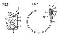
- a locking lock 1 which can advantageously be used for the new method is shown in FIGS. 1 and 2. It essentially consists of a cuboid housing, in which a push-through channel 3 and a push-in channel 4 are provided, which run at right angles to one another, the push-in channel 4 being separated from the push-through channel 3 by a wall 5 .
- This wall 5 offers, as will become clear below, a stop for the front end of a cable band 2.
- flexible locking tongues 6, 7 are provided, which have engagement teeth 8, 9 on one , can come with a sawtooth or a corrugation 10 provided surface of the cable band 2 into engagement.
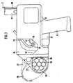
- a device suitable for carrying out the method is shown in a side view in FIG. 3.
- Its housing 13 has the shape of a pistol with a handle part 11, on which a trigger 12 is provided, by actuating which a processing cycle of the device can be initiated.
- a gear and a brake (not shown) are provided for driving the cable band 2 , which is fed to the device through a feed line 68 from a supply roll (not shown).
- the drive can take place via a flexible shaft 17 by an external electric motor. But it is also possible to integrate the electric motor into the housing.
- a carriage 19 In the housing 13, a carriage 19 is guided to move back and forth in the longitudinal direction. Lateral holding jaws 25 are provided at the front end of the slide 19 . Above them, a feed tube 23 for the locking locks 1 according to FIG. 1 enters the housing 13 from above. Through the feed tube 23 , the locking locks 1 can be fed from a loosely poured supply. The individual locking lock 1 falls into the space between the holding jaws 25 and is held by them in a provisional position.
- guide jaws 26, 27 are provided, which can be opened and closed like pliers, whereby in the closed state they form an approximately circular, closed, inner guide groove 29 .
- both positions of the pivotable guide jaw 27 are shown with different line widths.
- an outlet opening in the housing 13 of the device which opens into the space enclosed by the guide jaws 26, 27 or into the guide channel 29 .
- the outlet opening is shaped so that it can receive the holding jaws 25 of the slide 19 together with a locking lock 1 held therein.
- a cutting device (not shown) is provided on the housing 13 . It is arranged so that at the end of a working cycle, its knife can be moved horizontally and perpendicular to the plane of FIG. 3 immediately behind the outlet opening or the locking lock 1 placed therein, in order to be able to cut off the cable strip 2 just behind the locking lock 1 .
- the consumption of cable tape 2 is thus limited to what is really necessary and there is no waste.
- the new procedure is carried out in the following way.
- the device is brought into the predetermined position on a cable harness 59 to be bundled and fastened to a carrier part.
- a sensor on the device identifies this position via a coding system and the signal received is compared with a predetermined signal. If the two signals match, the feed of the locking locks 1 is automatically initiated through the feed tube 23 .
- the locking lock 1 is fed in such a way that its push-through channel 3 is in the line of alignment of an insertion tongue (not shown) which can be moved along the slide 19 and its push-in channel 4 points with the opening facing downward.
- the slide 19 is first moved forward , for example via a Bowden cable, taking the locking lock 1 held by its holding jaws 25 with it.
- the carriage 19 moves forward until the locking lock 1 is placed in the outlet opening of the device in the mounting position, where it is gripped and held by the lateral spring clips.
- a guide channel running through it at an angle inside the device also coincides with the outlet opening of the insertion channel for the cable band 2.
- the above-mentioned insertion tongue is moved forward along the slide 19 ; so that it slides under the first tooth 8 of the locking tongue 6 in the push-through channel 3 of the locking lock 1 .
- the cable band 2 is driven and advanced by an external electric motor via the flexible shaft 17 .
- the stop of the cable band 2 in the insertion channel 4 can be determined by continuously measuring the power consumption of the drive motor.
- a distance measurement can also be carried out on the cable strip 2 and the extent to which it has been conveyed can be determined.
- a light barrier can be provided on the side of the housing, preferably at the starting position of the cable end. The path that the cable band 2 has to travel from this point along the slide 19, through the guide groove 29 of the guide jaws 26, 27 back into the locking lock 1 , is constant.
- a signal can be derived from both measurements, which indicates when the end of the cable band 2 is engaged in the insertion channel 4 of the locking lock 1 and cannot be conveyed further.
- the engine is then reversed in its direction of rotation and thus from thrust to train.
- the cable band 2 is pulled back through the push-through channel 3 of the locking lock 1 and in the direction of the engagement teeth 8 until it tightly encompasses the cable bundle 59 .
- This point is also determined by measuring the power consumption of the engine.
- the assignment of the desired tightening force to the required motor power can be determined experimentally and incorporated into the program control. After reaching the tightening force determined in this way, the drive of the cable band 2 is stopped so that it is no longer under tension. Only then, when the cable band 2 is relieved, is the cutting process triggered on the cutting device (not shown) and the cable band 2 is cut off just behind the locking lock 1 .
- this ensures that the cable band 2 is always cut off at a defined point at a distance from the end face of the locking tongue 6 , which in turn ensures that the feed end of the cable band 2 is defined in the insertion channel 4 of the next locking lock 1 on the wall in each subsequent bundling process 5 abuts and comes with both teeth 9 of the locking tongue 7 in secure engagement and thus the optimal effect of the closure is achieved each time.
- the cable band 2 After the cable band 2 has been cut off, it is pulled back to its starting or zero position inside the device and the carriage 19 is moved back to its starting position.
- the guide jaws 26, 27 are opened manually and the device is guided to the next bundling point.
Landscapes
- Engineering & Computer Science (AREA)
- Mechanical Engineering (AREA)
- Basic Packing Technique (AREA)
- Weight Measurement For Supplying Or Discharging Of Specified Amounts Of Material (AREA)
- Installation Of Indoor Wiring (AREA)
- Insulated Conductors (AREA)
- Supports For Pipes And Cables (AREA)
- Electric Cable Installation (AREA)
- Processing Of Terminals (AREA)
Description
- Fig. 1
- einen Längsschnitt durch ein Verriegelungsschloß, wie es bei dem erfindungsgemäßen Gerät vorzugsweise zur Anwendung kommen soll,
- Fig. 2
- einen Längschnitt durch das Verriegelungsschloß gemäß Fig. 1 mit eingeschobenem Kabelband und
- Fig. 3
- die Seitenansicht eines Gerätes, mit dem das erfindungsgemäße Verfahren durch geführt werden kann.
Claims (4)
- Verfahren zum automatisierten Bündeln von Kabelsträngen, nach dem ein fortlaufend zuführbares, auf seiner einen Oberfläche eine Zahnung oder Riffelung (10) aufweisendes Kabelband, (2), angetrieben von einem Motor, vorgeschoben wird und mit seinem vorderen Ende durch ein mit in die Zahnung oder Riffelung (10) des Kabelbandes eingreifbaren Verriegelungsmitteln (6, 7) versehenes Verriegelungsschloß (1) hindurchgesteckt, um ein Kabelbündel geschlungen und in das Verriegelungschloß (1) zurückgeführt wird, wonach das Kabelband (2) durch Umsteuern der Drehrichtung seines Antriebsmotors entgegen seiner ursprünglichen Vorschubrichtung gespannt und hinter dem Verriegelungsschloß (2) abgeschnitten wird, dadurch gekennzeichnet, daß vor dem Abschneiden des Kabelbandes (2) der Antrieb des Kabelbandes (2) gestoppt wird und so das Kabelband (2) hinter dem Verriegelungsschloß (1) spannungslos gemacht wird.
- Verfahren nach Anspruch 1, dadurch gekennzeichnet, daß die Umsteuerung des Antriebsmotors zum Spannen des Kabelbandes (2) abhängig von der gemessenen Leistungsaufnahme oder vom gemessenen Drehmoment des Antriebsmotors und/oder abhängig von der gemessenen Vorschublänge des Kabelbandes (2) erfolgt und die Unterbrechung des Antriebs des Kabelbandes (2) abhängig von der gemessenen Leistungsaufnahme oder vom gemessenen Drehmoment des Antriebsmotors erfolgt.
- Verfahren nach Anspruch 1 oder 2, dadurch gekennzeichnet, daß ein Verriegelungsschloß (1) zur Anwendung kommt, welches, wie an sich bekannt, einen Durchsteckkanal (3) und, dazu um 90° versetzt, einen einseitig offenen Einsteckkanal (4) mit jeweils darin befindlichen Verriegelungszungen (6, 7) für den Eingriff an der Zahnung oder Riffelung (10) des Kabelbandes (2) aufweist, wobei der Einsteckkanal (4) durch eine Trennwand (5) gegenüber dem Durchsteckkanal (3) begrenzt ist, daß das von einer Vorratsrolle zugeführte Kabelband (2) mit seinem vorderen Ende zunächst durch den Durchsteckkanal (3) hindurch, um den zu bündelnden Kabelstrang (59) herum und dann in den Einsteckkanal (4) bis zum Anstoßen an der Trennwand (5) eingeführt wird und daß die beim Anstoßen des vorderen Endes des Kabelbandes (2) an der Trennwand (5) veränderte Leistungsaufnahme des Antriebsmotors als Signalwert für das Umsteuern des Antriebsmotors dient und/oder daß die ausgehend von einer bestimmten Startposition bis zum Anstoßen des vorderen Endes des Kabelbandes (2) an der Trennwand (5) benötigte Vorschublänge des Kabelbandes (2) als Kontroll- oder Signalwert für das Umsteuern des Antriebsmotors dient.
- Verfahren nach einem der Ansprüche 1 bis 3, dadurch gekennzeichnet, daß nach dem Umsteuern des Antriebsmotors die einer bestimmten Zugkraft am Kabelband (2) entsprechende Leistungsaufnahme des Antriebsmotors als Signalwert für die Unterbrechung des Antriebs für das Kabelband (2) dient.
Priority Applications (1)
| Application Number | Priority Date | Filing Date | Title |
|---|---|---|---|
| EP02027177A EP1295793B1 (de) | 1998-12-23 | 1999-12-16 | Automatisch arbeitendes Gerät zum Bündeln von Kabelsträngen |
Applications Claiming Priority (2)
| Application Number | Priority Date | Filing Date | Title |
|---|---|---|---|
| DE19859672A DE19859672C2 (de) | 1998-12-23 | 1998-12-23 | Verfahren zum automatisierten Bündeln von Kabelsträngen und automatisch arbeitendes Gerät zur Durchführung des Verfahrens |
| DE19859672 | 1998-12-23 |
Related Child Applications (1)
| Application Number | Title | Priority Date | Filing Date |
|---|---|---|---|
| EP02027177A Division EP1295793B1 (de) | 1998-12-23 | 1999-12-16 | Automatisch arbeitendes Gerät zum Bündeln von Kabelsträngen |
Publications (2)
| Publication Number | Publication Date |
|---|---|
| EP1013554A1 EP1013554A1 (de) | 2000-06-28 |
| EP1013554B1 true EP1013554B1 (de) | 2004-06-30 |
Family
ID=7892393
Family Applications (2)
| Application Number | Title | Priority Date | Filing Date |
|---|---|---|---|
| EP02027177A Expired - Lifetime EP1295793B1 (de) | 1998-12-23 | 1999-12-16 | Automatisch arbeitendes Gerät zum Bündeln von Kabelsträngen |
| EP99125061A Expired - Lifetime EP1013554B1 (de) | 1998-12-23 | 1999-12-16 | Verfahren zum Automatisierten Bündeln von Kabelsträngen |
Family Applications Before (1)
| Application Number | Title | Priority Date | Filing Date |
|---|---|---|---|
| EP02027177A Expired - Lifetime EP1295793B1 (de) | 1998-12-23 | 1999-12-16 | Automatisch arbeitendes Gerät zum Bündeln von Kabelsträngen |
Country Status (18)
| Country | Link |
|---|---|
| US (1) | US6513555B1 (de) |
| EP (2) | EP1295793B1 (de) |
| JP (2) | JP2002533273A (de) |
| KR (1) | KR100490482B1 (de) |
| CN (1) | CN1111488C (de) |
| AT (2) | ATE270221T1 (de) |
| AU (1) | AU744000B2 (de) |
| BR (1) | BR9916570A (de) |
| CA (1) | CA2355329A1 (de) |
| CZ (1) | CZ297616B6 (de) |
| DE (3) | DE19859672C2 (de) |
| ES (1) | ES2263728T3 (de) |
| HU (1) | HUP0200147A2 (de) |
| PL (1) | PL200519B1 (de) |
| PT (1) | PT1295793E (de) |
| RU (1) | RU2001119991A (de) |
| SK (1) | SK284876B6 (de) |
| WO (1) | WO2000038991A1 (de) |
Cited By (1)
| Publication number | Priority date | Publication date | Assignee | Title |
|---|---|---|---|---|
| TWI461332B (zh) * | 2012-01-31 | 2014-11-21 | Tang Yi Huang | 紮束帶 |
Families Citing this family (46)
| Publication number | Priority date | Publication date | Assignee | Title |
|---|---|---|---|---|
| DE50100795D1 (de) * | 2001-02-12 | 2003-11-20 | Hellermann Tyton Gmbh | Werkzeuganordnung zum Binden eines Gegenstands, insbesondere eines Kabelbaums |
| US7086426B2 (en) * | 2003-07-07 | 2006-08-08 | Thomas & Betts International, Inc. | Ergonomic cable tie installation tool |
| US7262385B2 (en) * | 2004-01-28 | 2007-08-28 | The Boeing Company | Material processing device |
| JP4624124B2 (ja) * | 2004-02-13 | 2011-02-02 | トーマス・アンド・ベッツ・インターナショナル・インコーポレーテッド | ケーブル・タイ・ツールのための張力と抗反跳の機構 |
| DE602005015370D1 (de) * | 2004-02-13 | 2009-08-27 | Thomas & Betts Internat Inc A | Kabelbindewerkzeug mit modularem Werkzeugkopf |
| SE527816C8 (sv) * | 2004-03-19 | 2006-09-12 | Mekanism med varabel transmission | |
| US7334610B2 (en) * | 2004-10-13 | 2008-02-26 | Panduit Corp. | Harness board fixture |
| US7908723B1 (en) * | 2005-06-01 | 2011-03-22 | Kodi Klip Corporation | Bar clip applicator |
| US20060248844A1 (en) * | 2005-05-03 | 2006-11-09 | Kodi Jon R | Bar clip with flared legs |
| USD587564S1 (en) | 2005-05-03 | 2009-03-03 | Kodi Klip Corporation | Bar clip with flared legs |
| US7764377B2 (en) | 2005-08-22 | 2010-07-27 | Applied Materials, Inc. | Spectrum based endpointing for chemical mechanical polishing |
| JP4820634B2 (ja) * | 2005-12-05 | 2011-11-24 | ヘラマンタイトン株式会社 | 外部駆動型結束工具及び人力駆動式定置型結束装置 |
| US7963392B2 (en) * | 2006-11-21 | 2011-06-21 | Kodi Klip Corporation | Bar connecting apparatus |
| US7891074B2 (en) * | 2006-11-21 | 2011-02-22 | Kodi Klip Corporation | Bar connecting apparatus |
| US7587872B2 (en) | 2007-02-05 | 2009-09-15 | Kodi Klip Corporation | Telescoping chair for supporting bars |
| US20090301025A1 (en) * | 2007-02-05 | 2009-12-10 | Kodi Klip Corporation | Telescoping Chair For Supporting Bars |
| TWI443047B (zh) * | 2008-03-27 | 2014-07-01 | Max Co Ltd | Bundle device |
| AU2009270321B2 (en) * | 2008-07-16 | 2013-06-27 | Robert Baird Watson | Improved cable tie |
| GB2463499A (en) * | 2008-09-16 | 2010-03-17 | Anthony John Schellens | Two piece cable tie |
| US8322006B1 (en) | 2009-04-20 | 2012-12-04 | Kodi Klip Corporation | Clip gun with pneumatic feed |
| US8776328B2 (en) | 2010-06-18 | 2014-07-15 | Kodi Klip Corporation | Rebar clip for joining different size bars |
| US8622440B2 (en) * | 2010-10-05 | 2014-01-07 | Ideal Industries, Inc. | Knot tying device and cartridge system for providing tying filament thereto |
| ES2581487T3 (es) | 2011-06-30 | 2016-09-06 | Hellermanntyton Corporation | Herramienta de tensado y corte de bridas para cables |
| USD692738S1 (en) | 2011-06-30 | 2013-11-05 | Hellermanntyton Corporation | Cable tie tensioning and cut-off tool |
| DE102013222924A1 (de) * | 2013-11-11 | 2015-05-28 | Hellermann Tyton Gmbh | Portables Kabelbindewerkzeug |
| KR101425340B1 (ko) * | 2014-02-19 | 2014-08-04 | 현대건설주식회사 | 현수교용 육각단면 와이어 스트랜드 제작장치에 이용되는 캐터필러, 클램프, 및 이를 이용한 현수교용 육각단면 와이어 스트랜드 제작장치 |
| US9797148B2 (en) | 2014-09-05 | 2017-10-24 | Kodi Klip, Llc | Clip applying apparatus |
| CN110406715B (zh) | 2014-12-12 | 2022-03-29 | 海尔曼太通股份有限公司 | 用于扎线带张紧和切断工具的复合的张力和校准机构 |
| JP2016188095A (ja) * | 2015-03-30 | 2016-11-04 | 住友電装株式会社 | 電線結束部材 |
| CN107416247B (zh) * | 2016-05-24 | 2019-08-09 | 桂林电子科技大学 | 一种线束自动绑扎设备的塑料扎带导向装置 |
| US10457429B1 (en) | 2016-09-03 | 2019-10-29 | Johnson International Corporation | Pair of jaws for a twist-tying machine |
| JP6932925B2 (ja) | 2016-12-29 | 2021-09-08 | マックス株式会社 | 結束機 |
| US11697515B2 (en) * | 2018-02-02 | 2023-07-11 | Shenzhen Swift Automation Technology Co., Ltd. | Slide block-based positioning mechanism and automatic tie tool having the same |
| CN108438296B (zh) * | 2018-04-12 | 2024-03-12 | 李昕宇 | 一种扎带自动扎紧切断装置及方法 |
| DE102018110184A1 (de) * | 2018-04-27 | 2019-10-31 | A. Raymond Et Cie Scs | Bindegerät und Verfahren zum automatisierten Bündeln von Kabelsträngen |
| CN112171568B (zh) | 2019-07-04 | 2024-08-09 | 伊利诺斯工具制品有限公司 | 手持式捆扎工具 |
| CN112706971B (zh) * | 2019-10-25 | 2023-05-26 | 泰科电子(上海)有限公司 | 线束绑胶带装置 |
| CN112622585B (zh) * | 2020-12-31 | 2022-08-02 | 东莞市凯菲特精密制造有限公司 | 一种半自动天窗水管的管卡安装设备 |
| CN113386992B (zh) * | 2021-06-22 | 2022-09-02 | 长春工程学院 | 一种汽车线束波纹管自动捆扎机 |
| DE202022102045U1 (de) | 2022-04-14 | 2023-07-19 | Hellermanntyton Gmbh | Automatische Bündelwerkzeugeinrichtung, ABT, für das Bündeln eines Bündelgutes mit einem Einteil-Binder mit Qualitätsüberwachung |
| DE202022106860U1 (de) | 2022-12-08 | 2024-03-12 | Hellermanntyton Gmbh | Zuführvorrichtung zum Führen und Bereitstellen von Einteil-Bindern |
| CN116054070B (zh) * | 2023-01-28 | 2023-06-27 | 湖南三湘银行股份有限公司 | 一种大量线缆集中连接装置 |
| EP4488185A1 (de) * | 2023-07-07 | 2025-01-08 | Illinois Tool Works Inc. | Bindewerkzeug |
| CN117108831B (zh) * | 2023-10-23 | 2023-12-19 | 潍坊炜桦冷弯机械制造有限公司 | 一种机电设备管线固定装置 |
| CN117485647B (zh) * | 2023-12-29 | 2024-04-02 | 太仓戴尔塔医疗科技有限公司 | 一种扎带机自动穿孔装置 |
| CN118494955B (zh) * | 2024-07-19 | 2024-09-13 | 江苏巨弘捆带制造有限公司 | 一种自锁式自动打包扣装置 |
Family Cites Families (11)
| Publication number | Priority date | Publication date | Assignee | Title |
|---|---|---|---|---|
| US3391440A (en) * | 1966-03-21 | 1968-07-09 | Gardner Denver Co | Mechanical tying tool |
| JPS5136680B2 (de) * | 1973-03-26 | 1976-10-09 | ||
| US3865156A (en) * | 1973-09-17 | 1975-02-11 | Panduit Corp | Powered strap tensioning and severing tool |
| US4571920A (en) * | 1983-11-29 | 1986-02-25 | Apv Burnett & Rolfe, Inc. | Beer keg capping machine |
| JPS6121316A (ja) * | 1984-07-10 | 1986-01-30 | 株式会社 ニフコ | 結束工具 |
| IT1227770B (it) * | 1987-07-01 | 1991-05-06 | Rta Italiana Spa | Procedimento e attrezzatura per la legatura automatica di fasci di conduttori, per mezzo di una banda continua. |
| US4862561A (en) * | 1988-12-21 | 1989-09-05 | Designs By Master Markets, Inc. | Irreversible tie strap with specialized clasp |
| JPH0754647Y2 (ja) * | 1990-11-27 | 1995-12-18 | 仁礼工業株式会社 | 電線等の結束具 |
| DE4212789C1 (de) * | 1992-04-16 | 1993-09-09 | A. Raymond Gmbh & Co. Kg, 7850 Loerrach, De | |
| IT1286370B1 (it) * | 1996-10-31 | 1998-07-08 | Thomas & Betts Corp | Utensile automatico per la installazione di fascette serracavi |
| US5769133A (en) * | 1997-04-08 | 1998-06-23 | Tyton-Hellermann Corp. | Power actuated handheld tensioning and cutoff tool |
-
1998
- 1998-12-23 DE DE19859672A patent/DE19859672C2/de not_active Expired - Fee Related
-
1999
- 1999-12-08 CZ CZ20012050A patent/CZ297616B6/cs not_active IP Right Cessation
- 1999-12-08 CA CA002355329A patent/CA2355329A1/en not_active Abandoned
- 1999-12-08 HU HU0200147A patent/HUP0200147A2/hu unknown
- 1999-12-08 PL PL349386A patent/PL200519B1/pl unknown
- 1999-12-08 JP JP2000590913A patent/JP2002533273A/ja active Pending
- 1999-12-08 KR KR10-2001-7006333A patent/KR100490482B1/ko not_active Expired - Fee Related
- 1999-12-08 SK SK840-2001A patent/SK284876B6/sk not_active IP Right Cessation
- 1999-12-08 BR BR9916570-8A patent/BR9916570A/pt not_active IP Right Cessation
- 1999-12-08 US US09/868,357 patent/US6513555B1/en not_active Expired - Lifetime
- 1999-12-08 RU RU2001119991/12A patent/RU2001119991A/ru not_active Application Discontinuation
- 1999-12-08 CN CN99814922A patent/CN1111488C/zh not_active Expired - Fee Related
- 1999-12-08 WO PCT/EP1999/009642 patent/WO2000038991A1/de not_active Ceased
- 1999-12-08 AU AU18637/00A patent/AU744000B2/en not_active Ceased
- 1999-12-16 DE DE59913398T patent/DE59913398D1/de not_active Expired - Lifetime
- 1999-12-16 EP EP02027177A patent/EP1295793B1/de not_active Expired - Lifetime
- 1999-12-16 EP EP99125061A patent/EP1013554B1/de not_active Expired - Lifetime
- 1999-12-16 DE DE59909850T patent/DE59909850D1/de not_active Expired - Fee Related
- 1999-12-16 PT PT02027177T patent/PT1295793E/pt unknown
- 1999-12-16 ES ES02027177T patent/ES2263728T3/es not_active Expired - Lifetime
- 1999-12-16 AT AT99125061T patent/ATE270221T1/de not_active IP Right Cessation
- 1999-12-16 AT AT02027177T patent/ATE325039T1/de not_active IP Right Cessation
-
2005
- 2005-07-07 JP JP2005199286A patent/JP2005330012A/ja active Pending
Cited By (1)
| Publication number | Priority date | Publication date | Assignee | Title |
|---|---|---|---|---|
| TWI461332B (zh) * | 2012-01-31 | 2014-11-21 | Tang Yi Huang | 紮束帶 |
Also Published As
| Publication number | Publication date |
|---|---|
| CZ20012050A3 (cs) | 2001-09-12 |
| DE59909850D1 (de) | 2004-08-05 |
| DE59913398D1 (de) | 2006-06-08 |
| AU744000B2 (en) | 2002-02-14 |
| PT1295793E (pt) | 2006-09-29 |
| CZ297616B6 (cs) | 2007-02-14 |
| HUP0200147A2 (en) | 2002-05-29 |
| DE19859672A1 (de) | 2000-06-29 |
| AU1863700A (en) | 2000-07-31 |
| ES2263728T3 (es) | 2006-12-16 |
| WO2000038991A1 (de) | 2000-07-06 |
| ATE325039T1 (de) | 2006-06-15 |
| PL349386A1 (en) | 2002-07-15 |
| PL200519B1 (pl) | 2009-01-30 |
| US6513555B1 (en) | 2003-02-04 |
| SK8402001A3 (en) | 2001-11-06 |
| CA2355329A1 (en) | 2000-07-06 |
| JP2005330012A (ja) | 2005-12-02 |
| SK284876B6 (sk) | 2006-01-05 |
| EP1295793B1 (de) | 2006-05-03 |
| ATE270221T1 (de) | 2004-07-15 |
| DE19859672C2 (de) | 2001-04-12 |
| KR20010093092A (ko) | 2001-10-27 |
| EP1295793A1 (de) | 2003-03-26 |
| JP2002533273A (ja) | 2002-10-08 |
| CN1331645A (zh) | 2002-01-16 |
| RU2001119991A (ru) | 2003-11-10 |
| CN1111488C (zh) | 2003-06-18 |
| BR9916570A (pt) | 2001-10-02 |
| KR100490482B1 (ko) | 2005-05-17 |
| EP1013554A1 (de) | 2000-06-28 |
Similar Documents
| Publication | Publication Date | Title |
|---|---|---|
| DE19859672C2 (de) | Verfahren zum automatisierten Bündeln von Kabelsträngen und automatisch arbeitendes Gerät zur Durchführung des Verfahrens | |
| DE3382610T2 (de) | Werkzeug zum anlegen von streifen von kabelbindeelementen und streifen dafuer. | |
| DE3873645T2 (de) | Verfahren und werkzeug zum automatischen binden von kabeln mit einem endlosen bindestreifen. | |
| DE3413099C2 (de) | Automatisch arbeitendes Werkzeug zum Umwickeln von Drahtbündeln od. dgl. | |
| DE69505767T2 (de) | Verfahren und Vorrichtung für eine Umschnürungsmaschine | |
| DE2700533C3 (de) | Vorrichtung zur Bildung einer gespannten Bandschlaufe um eine Verpackung | |
| DE3243906A1 (de) | Riemenfoerderer fuer den transport von drahtstuecken | |
| DE2720027B2 (de) | Bindewerkzeug zum Verdrillen der freien Enden eines Bindedrahtes | |
| DE69718555T2 (de) | Vorrichtung zum Stapeln von Blättern, insbesondere Geldscheinen, und zum Übertragen der Stapel | |
| EP0178518B1 (de) | Verfahren und Vorrichtung zum Umschnüren eines Ballens od. dgl. | |
| DE69110017T2 (de) | Vorrichtung und Verfahren zum Binden von elektrischen Kabeln. | |
| EP0142001B1 (de) | Vorrichtung zum Binden eines Bündels elektrischer Leitungen | |
| WO2019206748A1 (de) | Bindegerät und verfahren zum automatisierten bündeln von kabelsträngen | |
| DE19538987A1 (de) | Pakettiermaschine | |
| DE3426251A1 (de) | Umreifungsvorrichtung | |
| EP0583325B1 (de) | Anordnung zum ordnen und binden eines langgestreckten gegenstandes, insbesondere eines kabelbaums | |
| DE4408568A1 (de) | Automatische Maschine zum Binden von Rohrbündeln oder ähnlichem | |
| EP0800476B1 (de) | Verfahren zum binden von gebündelten gegenständen, insbesondere kabelstücken, sowie dazugehörige vorrichtung und ein bindematerial | |
| EP1050462B1 (de) | Spanneinheit für eine Umreifungsmaschine | |
| EP0499042B1 (de) | Verfahren zum Herstellen eines Kabelbaumes und Vorrichtung dazu | |
| DE3819764C2 (de) | ||
| EP0596370A1 (de) | Anordnung zum Binden | |
| DE102010016774A1 (de) | Vorrichtung zum Umreifen von Packstücken mit Umreifungsband | |
| DE69827743T2 (de) | Verbessertes mit ultraschall arbeitendes bindewerkzeug | |
| DE2819585A1 (de) | Verfahren zum entfernen von verschlussgliedern aus den laengsstraengen von reissverschluessen und vorrichtung zum durchfuehren dieses verfahrens |
Legal Events
| Date | Code | Title | Description |
|---|---|---|---|
| PUAI | Public reference made under article 153(3) epc to a published international application that has entered the european phase |
Free format text: ORIGINAL CODE: 0009012 |
|
| AK | Designated contracting states |
Kind code of ref document: A1 Designated state(s): AT BE CH CY DE DK ES FI FR GB GR IE IT LI LU MC NL PT SE |
|
| AX | Request for extension of the european patent |
Free format text: AL;LT;LV;MK;RO;SI |
|
| 17P | Request for examination filed |
Effective date: 20001228 |
|
| AKX | Designation fees paid |
Free format text: AT BE CH CY DE DK ES FI FR GB GR IE IT LI LU MC NL PT SE |
|
| 17Q | First examination report despatched |
Effective date: 20020801 |
|
| RTI1 | Title (correction) |
Free format text: METHOD FOR THE AUTOMATIC BUNDLING OF CABLE STRANDS |
|
| GRAP | Despatch of communication of intention to grant a patent |
Free format text: ORIGINAL CODE: EPIDOSNIGR1 |
|
| GRAS | Grant fee paid |
Free format text: ORIGINAL CODE: EPIDOSNIGR3 |
|
| GRAA | (expected) grant |
Free format text: ORIGINAL CODE: 0009210 |
|
| AK | Designated contracting states |
Kind code of ref document: B1 Designated state(s): AT BE CH CY DE DK ES FI FR GB GR IE IT LI LU MC NL PT SE |
|
| PG25 | Lapsed in a contracting state [announced via postgrant information from national office to epo] |
Ref country code: NL Free format text: LAPSE BECAUSE OF FAILURE TO SUBMIT A TRANSLATION OF THE DESCRIPTION OR TO PAY THE FEE WITHIN THE PRESCRIBED TIME-LIMIT Effective date: 20040630 Ref country code: IT Free format text: LAPSE BECAUSE OF FAILURE TO SUBMIT A TRANSLATION OF THE DESCRIPTION OR TO PAY THE FEE WITHIN THE PRESCRIBED TIME-LIMIT;WARNING: LAPSES OF ITALIAN PATENTS WITH EFFECTIVE DATE BEFORE 2007 MAY HAVE OCCURRED AT ANY TIME BEFORE 2007. THE CORRECT EFFECTIVE DATE MAY BE DIFFERENT FROM THE ONE RECORDED. Effective date: 20040630 Ref country code: IE Free format text: LAPSE BECAUSE OF FAILURE TO SUBMIT A TRANSLATION OF THE DESCRIPTION OR TO PAY THE FEE WITHIN THE PRESCRIBED TIME-LIMIT Effective date: 20040630 Ref country code: FR Free format text: LAPSE BECAUSE OF FAILURE TO SUBMIT A TRANSLATION OF THE DESCRIPTION OR TO PAY THE FEE WITHIN THE PRESCRIBED TIME-LIMIT Effective date: 20040630 Ref country code: FI Free format text: LAPSE BECAUSE OF FAILURE TO SUBMIT A TRANSLATION OF THE DESCRIPTION OR TO PAY THE FEE WITHIN THE PRESCRIBED TIME-LIMIT Effective date: 20040630 Ref country code: CY Free format text: LAPSE BECAUSE OF FAILURE TO SUBMIT A TRANSLATION OF THE DESCRIPTION OR TO PAY THE FEE WITHIN THE PRESCRIBED TIME-LIMIT Effective date: 20040630 |
|
| REG | Reference to a national code |
Ref country code: GB Ref legal event code: FG4D Free format text: NOT ENGLISH Ref country code: CH Ref legal event code: EP |
|
| REG | Reference to a national code |
Ref country code: IE Ref legal event code: FG4D Free format text: GERMAN |
|
| REF | Corresponds to: |
Ref document number: 59909850 Country of ref document: DE Date of ref document: 20040805 Kind code of ref document: P |
|
| PG25 | Lapsed in a contracting state [announced via postgrant information from national office to epo] |
Ref country code: SE Free format text: LAPSE BECAUSE OF FAILURE TO SUBMIT A TRANSLATION OF THE DESCRIPTION OR TO PAY THE FEE WITHIN THE PRESCRIBED TIME-LIMIT Effective date: 20040930 Ref country code: GR Free format text: LAPSE BECAUSE OF FAILURE TO SUBMIT A TRANSLATION OF THE DESCRIPTION OR TO PAY THE FEE WITHIN THE PRESCRIBED TIME-LIMIT Effective date: 20040930 Ref country code: DK Free format text: LAPSE BECAUSE OF FAILURE TO SUBMIT A TRANSLATION OF THE DESCRIPTION OR TO PAY THE FEE WITHIN THE PRESCRIBED TIME-LIMIT Effective date: 20040930 |
|
| PG25 | Lapsed in a contracting state [announced via postgrant information from national office to epo] |
Ref country code: ES Free format text: LAPSE BECAUSE OF FAILURE TO SUBMIT A TRANSLATION OF THE DESCRIPTION OR TO PAY THE FEE WITHIN THE PRESCRIBED TIME-LIMIT Effective date: 20041011 |
|
| GBT | Gb: translation of ep patent filed (gb section 77(6)(a)/1977) | ||
| PG25 | Lapsed in a contracting state [announced via postgrant information from national office to epo] |
Ref country code: LU Free format text: LAPSE BECAUSE OF NON-PAYMENT OF DUE FEES Effective date: 20041216 Ref country code: AT Free format text: LAPSE BECAUSE OF NON-PAYMENT OF DUE FEES Effective date: 20041216 |
|
| PG25 | Lapsed in a contracting state [announced via postgrant information from national office to epo] |
Ref country code: MC Free format text: LAPSE BECAUSE OF NON-PAYMENT OF DUE FEES Effective date: 20041231 Ref country code: LI Free format text: LAPSE BECAUSE OF NON-PAYMENT OF DUE FEES Effective date: 20041231 Ref country code: CH Free format text: LAPSE BECAUSE OF NON-PAYMENT OF DUE FEES Effective date: 20041231 Ref country code: BE Free format text: LAPSE BECAUSE OF NON-PAYMENT OF DUE FEES Effective date: 20041231 |
|
| NLV1 | Nl: lapsed or annulled due to failure to fulfill the requirements of art. 29p and 29m of the patents act | ||
| REG | Reference to a national code |
Ref country code: IE Ref legal event code: FD4D |
|
| PLBE | No opposition filed within time limit |
Free format text: ORIGINAL CODE: 0009261 |
|
| 26N | No opposition filed |
Effective date: 20050331 |
|
| EN | Fr: translation not filed | ||
| BERE | Be: lapsed |
Owner name: A. *RAYMOND & CIE Effective date: 20041231 |
|
| REG | Reference to a national code |
Ref country code: CH Ref legal event code: PL |
|
| BERE | Be: lapsed |
Owner name: A. *RAYMOND & CIE Effective date: 20041231 |
|
| PG25 | Lapsed in a contracting state [announced via postgrant information from national office to epo] |
Ref country code: PT Free format text: LAPSE BECAUSE OF NON-PAYMENT OF DUE FEES Effective date: 20041130 |
|
| PGFP | Annual fee paid to national office [announced via postgrant information from national office to epo] |
Ref country code: DE Payment date: 20081203 Year of fee payment: 10 |
|
| PGFP | Annual fee paid to national office [announced via postgrant information from national office to epo] |
Ref country code: GB Payment date: 20081210 Year of fee payment: 10 |
|
| GBPC | Gb: european patent ceased through non-payment of renewal fee |
Effective date: 20091216 |
|
| PG25 | Lapsed in a contracting state [announced via postgrant information from national office to epo] |
Ref country code: DE Free format text: LAPSE BECAUSE OF NON-PAYMENT OF DUE FEES Effective date: 20100701 |
|
| PG25 | Lapsed in a contracting state [announced via postgrant information from national office to epo] |
Ref country code: GB Free format text: LAPSE BECAUSE OF NON-PAYMENT OF DUE FEES Effective date: 20091216 |