EP1011908B1 - Vorrichtung zur herstellung von bandsägeblättern - Google Patents
Vorrichtung zur herstellung von bandsägeblättern Download PDFInfo
- Publication number
- EP1011908B1 EP1011908B1 EP98951371A EP98951371A EP1011908B1 EP 1011908 B1 EP1011908 B1 EP 1011908B1 EP 98951371 A EP98951371 A EP 98951371A EP 98951371 A EP98951371 A EP 98951371A EP 1011908 B1 EP1011908 B1 EP 1011908B1
- Authority
- EP
- European Patent Office
- Prior art keywords
- division
- punch
- tooth
- punching
- spacing
- Prior art date
- Legal status (The legal status is an assumption and is not a legal conclusion. Google has not performed a legal analysis and makes no representation as to the accuracy of the status listed.)
- Expired - Lifetime
Links
- 239000000463 material Substances 0.000 claims abstract description 60
- 238000004080 punching Methods 0.000 claims abstract description 27
- 239000002184 metal Substances 0.000 claims abstract 2
- 230000033001 locomotion Effects 0.000 claims description 11
- 238000000034 method Methods 0.000 abstract description 9
- 238000004519 manufacturing process Methods 0.000 description 14
- 230000005641 tunneling Effects 0.000 description 7
- 238000007654 immersion Methods 0.000 description 3
- 230000018109 developmental process Effects 0.000 description 2
- 230000001154 acute effect Effects 0.000 description 1
- 230000001419 dependent effect Effects 0.000 description 1
- 238000005096 rolling process Methods 0.000 description 1
- 238000010079 rubber tapping Methods 0.000 description 1
- 238000007789 sealing Methods 0.000 description 1
- 230000036346 tooth eruption Effects 0.000 description 1
- 238000004804 winding Methods 0.000 description 1
Images


Classifications
-
- B—PERFORMING OPERATIONS; TRANSPORTING
- B23—MACHINE TOOLS; METAL-WORKING NOT OTHERWISE PROVIDED FOR
- B23D—PLANING; SLOTTING; SHEARING; BROACHING; SAWING; FILING; SCRAPING; LIKE OPERATIONS FOR WORKING METAL BY REMOVING MATERIAL, NOT OTHERWISE PROVIDED FOR
- B23D65/00—Making tools for sawing machines or sawing devices for use in cutting any kind of material
- B23D65/02—Making saw teeth by punching, cutting, or planing
Definitions
- the present invention relates to a device according to Preamble of claim 1.
- Such devices are used for the production of band saw blades.
- recesses are made laterally from the Band material punched out. In this way arise in Band material the sharpened teeth, which then only still need to be restricted.
- the object of the present invention is the known Develop the device so that the speed at the production of the recesses while maintaining the precise geometric relationships can be multiplied.
- the invention solves this problem with the features of Main claim.
- the advantage of the invention is that multiplication the tooth production speed for band saw blades is possible without the desired tooth tip sharpness, which results only from punching out the teeth, is affected.
- the invention can also be used in general Use production of recesses from tape material. A Limitation of the invention to the manufacture of saw teeth is therefore not necessary.
- the basis of the invention is a change in the stride lengths of the individual advance steps. To a predetermined number a so-called overtaking step follows from individual steps.
- each of the individual steps has the step length of the division, In this case, n-1 advance steps are required.
- the small advance steps make it even more so non-punched tape material between the punches gradually filled with recesses.
- the overtaking step has the step length of the punch spacing plus once the step length of the division.
- the punching speed can be achieved with the invention to produce the recesses without changing the Multiply the number of strokes per second.
- the level of multiplication ultimately depends on the number of stamps used.
- the stamps can be connected in one piece.
- a further training provides two stamps, in which the punch spacing is twice the division.
- This development of the invention is carried out alternately a short advance, a long advance (Overtaking step), a short advance step etc.
- the sequence of steps is therefore alternately short - long - short - long etc.
- suitable selection of the punch spacing and the short or long stride length can be so saws can be easily produced with teeth.
- the teeth are moved back with their tooth tips Cutting teeth lie on the outer edge of the strip material.
- the system's dynamic vibrations remain within narrowest limits.
- the invention is of particular importance for the production of saw teeth. These become one side Band saw blade punched out. Here it comes in particular exactly to punch the tips of the teeth sharply. For this So far, it was assumed that each tooth was for itself must be punched.
- a punching tool for the immediate production of two Adjacent teeth in one punching step can meet this requirement not meet.
- the one between the punches Tooth would not get the required sharpness. This is because the space between the tooth punches technically always have a fillet. The result of this resulting tooth shape would follow this fillet. This could possibly be eliminated by subsequent grinding become.
- a further development of the invention provides punch stamps and tape material relative to each other across or perpendicular to to make the longitudinal edges of the strip material movable.
- stamps that have a distance of twice the division from each other of particular importance that between two transverse positions and between a long and a short advance can be changed in each case.
- the long advance step corresponds to the overtaking step, with which two tooth recesses are skipped.
- the short propulsion step is shifted to the outside Transverse position between two deep tooth recesses The tape position is approached so that it is on the right and left two new sharp tooth tips are created from the punch, however, the associated depth of the tooth recess is less.
- the figures show a punching machine 100 for punching out of recesses with predetermined and each equally large distances from each other from a metallic Strip material 2.
- the distances that the recesses from each other ingest are called division 45. The distances repeat themselves regularly.
- the advance steps have a length that depends on the pitch 45 is. Between the advance steps there are so-called Propulsion rest periods.
- the strip material 2 is taken from a supply reel 3 withdrawn, passed under a punching die 14 and wound on a take-up spool 4.
- the unwind spool 3 is here via an electronically controlled unwind drive 5 driven in the unwinding direction.
- the take-up spool 4 is here also one electronically controlled take-up drive 6 driven.
- Abwickelantrieb 5 and take-up drive 6 are set so that between the unwind spool 3 and the punch die 14 a leading sealing zone 7 and between the punch die 14 and the take-up reel 4 a trailing creasing zone 8 arises.
- the belt conveyor 9 has an input-side conveyor roller pair 10 and an output-side Pair of conveyor rollers 11.
- the conveyor roller pairs 10 and 11 are via traction drives 12 and 13 with the belt conveyor motor 22 coupled, which is also electronically controlled is.
- a belt path measuring device 15 is provided, which with a measuring wheel 16 on the lower broad side 17 of the strip material 2 is present.
- a measuring wheel 16 On the lower broad side 17 of the strip material 2 is present.
- the conveyed strip material can are promoted forward by predetermined stride lengths.
- the path actually traveled serves this Measuring wheel 16. Since the strip material between the pair of conveyor rollers on the input side 10 and pair of output rollers 11 on the output side is kept taut, errors are excluded.
- the belt conveyor motor 22 is a servo motor, which is controlled by a servo amplifier 23.
- the punch 27a and 27b are seated a common toothed slide 24 which is perpendicular to the Tape material 2 is driven so clocked that in the Driving idle times the punch 27a, 27b with their punch ends dip into the strip material 2 underneath.
- the toothed slide 24 is vertical Rolling bearing guide 26 is slidably mounted in the machine housing 25.
- a toothed slide eccentric is used to move up and down 29, via an electronically controlled punch motor 30 is always set in motion for one revolution, when the belt conveyor motor is stopped. This is done after a certain regularity, which will be discussed later.
- this regularity is a timed one Drive of the punch die, which always starts if the tape material is not advanced.
- toothed slide eccentric 29 connected encoder 31 and a fixed slave 32, which is initialized by the encoder 31.
- the signal of the The controller 32 is abandoned and used for the control device 21 the coordination between the successive belt conveyor steps and the stroke movements 58 of the toothed slide 24.
- a base plate is used 33, which crosses the toothed slide 24 via an adjusting wheel 39 can be adjusted.
- the base plate 33 there is a band back stop 34, formed by two fixed bearings.
- the roller bearing 35,36 is the strip material 2 with the smooth Back side while the opposite parallel edge with teeth.
- the tape material 2 with the straight tape back is guided on the strap back stop 34. This enables one precise adherence to the tooth tip line in the range of 1 / 500ste1 millimeters and less because the straight Outer edge of the strip material 2 constantly and continuously the band back stop 34 is guided.
- stamping stamps 27a, 27b and the strip material 2 serve an adjusting wheel 39, which has a movement via an adjusting spindle 38 of the base plate 33 in the adjustment direction 37.
- the adjusting spindle 38 is in a spindle bearing 40 stationary and grips with its spindle thread 41 into a counter thread of the base plate 33.
- the base plate 33 is on the side on a longitudinal guide 42 performed in parallel. Via the respective rotary position of the adjustment spindle 38 thus results in the basic position of the base plate 33rd
- punch distance 49 This distance is referred to as punch distance 49. Both punch 27a, 27b have an identical profile.
- the strip conveyor 9 controlled such that after a predetermined number of small advance steps 56 with the respective step length the division an overtaking step 57 is carried out, the Stride length is equal to a predetermined other multiple the split.
- the punch spacing is decisive for this. Is the distance between the punch 27a, 27b than an n-fold the division, the belt conveyor must 9 first perform n-1 tunneling steps, each of the Advancing steps with the step length of the division. In order to becomes the band area between the stamps gradually filled with recesses. Then follows the overtaking step.
- the overtaking step then has a stride length that is equal to (n + 1) times the division.
- the respective Division 45 is also impressed on the control device 21 as the desired value become.
- punch spacing 49 it is also necessary to use the so-called punch spacing 49 to give up the control device 21, so that from there the individual short tunneling steps are generated can.
- control device 21 is provided to enter a further setpoint, which is analogous to the respective Transverse position 53 exists. This makes the immersion depth practical meant, which of the tips of the tooth stamp 27a, 27b is realized in the strip material 2.
- this size is also the control device 21 to give up.
- FIGS. 1 to 6 there are 2 punch stamps 27a, 27b each arranged in a single die. 1 and 2 show the punch spacing 49 can be adjustable.
- the punch spacing 49 can be adjustable.
- 51 are provided as an example, which in the Toothed slide 24 are embedded.
- For attaching the punch 27a, 27b serve hammer screws 52, which the elongated holes 50 reach behind.
- the variation of the transverse position can vary from punching to Punching process. In this case, for each of the following To move to a different transverse position his.
- the different transverse positions can, however can also be approached according to other laws.
- the punches 27a and 27b have one Distance from each other, which corresponds to n times the division.
- the division t here is the length of the line between two successive teeth, designated 45 is.
- the punching tool preceding in the conveying direction 46 27b is accordingly at a distance from the one lagging in the conveying direction Punching tool 27a of n-1 times division.
- the strip material 2 must have a total of n-1 advance steps experienced, each of which is the length of the stride the division has t.
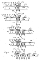
- 3b shows a case for the special training, in which the punch 27a, 27b the distance of the Have double the division.
- FIGS. 4 a to e This case is shown again in FIGS. 4 a to e.
- the Fig.4a and b correspond to what was said to Fig.3b.
- a transverse drive can 54 with which the relative position in Transverse direction between the strip material and the stamping punch, motor-driven can be changed.
- a change calls the transverse position between punch and tape material different deep recesses from the band material.
- the Band material kept at rest. Then there is a jacking step the length 59, here as a short advance referred to as.
- the length of the advance step is measured by the distance the tooth tips with the not so deep interdental space ingest t from each other.
- the depth of the interdental space is by the transverse position 55 of the toothed slide 24 set.
- the tips of the punching tools 27a, 27b are inserted Slipped out of the strip material 2, to the extent that the Except the interdental space at the required depth t becomes.
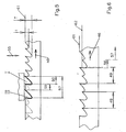
- This process creates teeth, the tips of their teeth all lie on the matching tooth tip line 61.
- the method according to FIG. 6 differs from this.
- the tape material is in the same small size Propulsion steps 56 followed by an overtaking step 57 promoted.
- the transverse position of the punch can also be used be changed.
- the tooth tip lines 61, 62 lie on different ones Levels. With each deeply retracted Stamping tool 27a, 27b or in the short advance steps tooth tips 62 are shifted back Punching tool 27a, 27b or during the long advance steps tooth tips arise on the outer tooth tip line 61 lie.
- the transverse drive 54 should accordingly be clocked.
- a connection line from the central serves this purpose Control device 21 to the motor of the transverse drive 54, the in turn geared with a transversely to the strip material 2 movable carriage is coupled.
- the timing is essential for the invention between the advance steps and the intermediate steps Propulsion rest periods. This takes place during the tunneling rest periods Stroke movement 58 of the punching slide 24. Before or after is the respective transverse position of the punch carriage 24 set by the transverse drive 54.
- the encoder is used to coordinate the timing 31, the slave 32 so after each rotational movement activated that the control device 21 a corresponding Signal can be impressed.
- the punches can also be connected to one another in one piece be and so an unchangeable stamp spacing exhibit.
Landscapes
- Engineering & Computer Science (AREA)
- Mechanical Engineering (AREA)
- Punching Or Piercing (AREA)
- Perforating, Stamping-Out Or Severing By Means Other Than Cutting (AREA)
- Control And Other Processes For Unpacking Of Materials (AREA)
Description
- Fig.1
- ein Ausführungsbeispiel der Erfindung in Ansicht von vorn,
- Fig.2
- ein Ausführungsbeispiel der Erfindung aus Sicht II-II gemäß Fig.1,
- Fig.3a
- ein Ausführungsbeispiel der Erfindung in allgemeiner Form,
- Fig.3b
- ein Ausführungsbeispiel der Erfindung mit Stanzstempelabstand gleich zweimal Teilung,
- Fig.4a bis 4e
- eine Folge aus Arbeitszyklen mit Darstellung des Wechsels zwischen Vortriebsschritt gleich Schrittlänge der Teilung und Überholschritt,
- Fig.5
- ein Ausführungsbeispiel für Vortriebsschritte unterschiedlicher Länge für unterschiedliche Querpositionen, und
- Fig.6
- ein Ausführungsbeispiel für Vortriebsschritte konstanter Länge bei unterschiedlichen Querpositionen.
- 100
- Stanzmaschine
- 2
- Bandmaterial
- 3
- Abwickelspule
- 4
- Aufwickelspule
- 5
- Aufwickelantrieb
- 6
- Abwickelantrieb
- 7
- vorauslaufende Verschlappungszone
- 8
- nachlaufende Verschlappungszone
- 9
- Bandfördereinrichtung
- 10
- eingangsseitiges Förderrollenpaar
- 11
- ausgangsseitiges Förderrollenpaar
- 12
- Zugmittelantrieb für 10
- 13
- Zugmittelantrieb für 11
- 14
- Stanzmatrize
- 15
- Bandwegmeßeinrichtung
- 16
- Meßrad
- 17
- Breitseite
- 18
- gegenüberliegende Breitseite
- 19
- Anpreßrolle
- 20
- Wegsignalleitung
- 21
- Steuereinrichtung
- 22
- Bandfördermötor
- 23
- Servoverstärker
- 24
- Zahnschlitten
- 25
- Maschinengehäuse
- 26
- Wälzlagerführung
- 27a
- Stanzstempel
- 27b
- Stanzstempel
- 28
- Gegenplatte
- 29
- Zahnschlittenexenter
- 30
- Stanzmotor
- 31
- Geber
- 32
- Nehmer
- 33
- Basisplatte
- 34
- Bandrückenanschlag
- 35
- Wälzlager.
- 36
- Wälzlager
- 37
- Verstellrichtung
- 38
- Verstellspindel
- 39
- Verstellrad
- 40
- Spindellagerung
- 41
- Spindelgewinde
- 42
- Längsführung
- 43
- Drehachse der Förderrolle
- 44
- Neigungswinkel
- 45
- Teilung
- 46
- Förderrichtung
- 47
- Förderkraft
- 48
- Anpreßkraft
- 49
- Stanzstempelabstand
- 50
- Langloch
- 51
- Langloch
- 52
- Hammerschraube
- 53
- Querposition
- 54
- Querantrieb
- 55
- Querbewegung
- 56
- Vortriebsschritt mit Teilungslänge
- 57
- Überholschritt
- 58
- Hubbewegung des Zahnschlittens
- 59
- Zahnspitzenabstand, kurz
- 60
- Zahnspitzenabstand, lang
- 61
- Zahnspitzenlinie, außenliegende
- 62
- Zahnspitzenlinie, innenliegende
- T, t
- Tiefe des jeweiligen Zahnzwischenraums
- I - IV
- Zahnzwischenraum eines Überholschritts
- I' - IV'
- Zahnzwischenraum des nächsten Überholschritts
- I" - IV''
- Zahnzwischenraum des übernächsten Überholschritts
Claims (9)
- Vorrichtung zur Herstellung von Bandsägeblättern durch Ausstanzen einzelner angeschärfter Sägezähne vorgegebener Breite mit vorbestimmten und sich jeweils wiederholenden Abständen voneinander aus einem metallischen Bandmaterial (2), welches mittels Bandfördereinrichtung (9) diskontinuierlich in Vortriebsschritten von vorgegebenen und von der Teilung (45) abhängenden Längen gefördert und ausschließlich in den Vortriebsruhezeiten mittels Stanzstempel einer zum Bandmaterial (2) querbeweglichen und getaktet angetriebenen Stanzmatrize (14) mit angeschärften Sägezähnen versehen wird wobei das Anschärfen durch den Stanzschritt für den folgenden Zahn geschieht, dadurch gekennzeichnet, daß1.0 zwei Stanzstempel (27a,27b) an der Stanzmatrize vorgesehen sind, welche parallel zu den Längskanten des Bandmaterials (2) liegen und welche1.1 voneinander den Abstand (49) eines ganzzahligen Vielfachen (n≥2) der Teilung (45) haben, und daß1.2 die Bandfördereinrichtung (9) nach einer Anzahl von (n-1) kleinen Vortriebsschritten, von denen jeder die Schrittlänge der Teilung (45) hat,1.2.1 einen Überholschritt ausführt, dessen Schrittlänge gleich ist dem (n+1)-fachen der Teilung (45).
- Vorrichtung nach Anspruch 1, dadurch gekennzeichnet, daß die zwei Stanzstempel (27a,27b) an einer einzigen Stanzmatrize (14) sitzen.
- Vorrichtung nach Anspruch 2, dadurch gekennzeichnet, daß die zwei Stanzstempel (27a,27b) einstückig miteinander verbunden sind.
- Vorrichtung nach Anspruch 2, dadurch gekennzeichnet, daß der Stanzstempelabstand (49) einstellbar ist.
- Vorrichtung nach einem der Ansprüche 1 bis 4, dadurch gekennzeichnet, daß Stanzstempel (27a,27b) und Bandmaterial (2) zur Erzielung unterschiedlicher Querpositionen (53) der Ausnehmungen relativ zueinander quer, vorzugsweise senkrecht zu den Längskanten des Bandmaterials (2) verfahrbar sind.
- Vorrichtung nach Anspruch 5, dadurch gekennzeichnet, daß die Schrittlänge (45) der Vortriebsschritte in Abhängigkeit von den unterschiedlichen Querpositionen (T, t) der Ausnehmungen variierbar ist.
- Vorrichtung nach Anspruch 5, dadurch gekennzeichnet, daß die Schrittlänge (45) der Vortriebsschritte unabhängig von den unterschiedlichen Querpositionen (T,t) der Ausnehmungen konstant bleibt.
- Vorrichtung nach Anspruch 6, dadurch gekennzeichnet, daß der Stanzstempelabstand (49) das Zweifache der Teilung (45) ist und daß zwischen zwei Querpositionen (T,t) und zwischen einem langen (60) und einem kurzen (59) Vortriebsschritt jeweils gewechselt wird, worauf ein Überholschritt (57) durchgeführt wird.
- Vorrichtung nach einem der Ansprüche 1 bis 8, dadurch gekennzeichnet, daß die Schrittlänge der Vortriebsschritte so variiert wird, daß ohne Veränderung der Querposition der Stanzwerkzeuge die entstehenden Zahnspitzen auf unterschiedlichen Zahnspitzenlinien (61, 62) liegen.
Applications Claiming Priority (3)
| Application Number | Priority Date | Filing Date | Title |
|---|---|---|---|
| DE19739605 | 1997-09-09 | ||
| DE19739605A DE19739605A1 (de) | 1997-09-09 | 1997-09-09 | Vorrichtung zum Herausstanzen von Ausnehmungen |
| PCT/EP1998/005740 WO1999012687A1 (de) | 1997-09-09 | 1998-09-09 | Vorrichtung zur herstellung von bandsägeblättern |
Publications (2)
| Publication Number | Publication Date |
|---|---|
| EP1011908A1 EP1011908A1 (de) | 2000-06-28 |
| EP1011908B1 true EP1011908B1 (de) | 2002-01-30 |
Family
ID=7841793
Family Applications (1)
| Application Number | Title | Priority Date | Filing Date |
|---|---|---|---|
| EP98951371A Expired - Lifetime EP1011908B1 (de) | 1997-09-09 | 1998-09-09 | Vorrichtung zur herstellung von bandsägeblättern |
Country Status (4)
| Country | Link |
|---|---|
| EP (1) | EP1011908B1 (de) |
| AT (1) | ATE212579T1 (de) |
| DE (2) | DE19739605A1 (de) |
| WO (1) | WO1999012687A1 (de) |
Families Citing this family (7)
| Publication number | Priority date | Publication date | Assignee | Title |
|---|---|---|---|---|
| RU2312744C2 (ru) * | 2005-09-13 | 2007-12-20 | Закрытое акционерное общество "Инструмент" (ЗАО "Инструмент") | Способ и штамп для изготовления зубьев пилы (варианты) |
| CN103042273B (zh) * | 2013-01-28 | 2015-04-29 | 东莞市萨浦刀锯有限公司 | 精密全自动带锯开齿机组 |
| CN108213319A (zh) * | 2018-01-19 | 2018-06-29 | 湖州众诚链传动制造厂 | 一种链条内链板安全冲孔设备 |
| JP7368295B2 (ja) * | 2020-03-31 | 2023-10-24 | 本田技研工業株式会社 | 燃料電池用セパレータの製造方法、および燃料電池用セパレータの製造装置 |
| SE544496C2 (en) * | 2020-07-15 | 2022-06-21 | Swealand Hus & Fasadteknik Ab | Method and apparatus for refurbishing an oscillating multi-tool blade |
| CN112170960B (zh) * | 2020-09-04 | 2022-06-21 | 南京灵雀智能制造有限公司 | 一种锯条制作装置 |
| CN112475460A (zh) * | 2020-11-17 | 2021-03-12 | 东台艺新科技有限公司 | 一种连续式的锯条压齿机 |
Family Cites Families (5)
| Publication number | Priority date | Publication date | Assignee | Title |
|---|---|---|---|---|
| US3540317A (en) * | 1967-12-12 | 1970-11-17 | Capewell Mfg Co | Method of making saw blades |
| SE452564B (sv) * | 1983-02-07 | 1987-12-07 | Santrade Ltd | Sag och sett att framstella densamma |
| DE4010875A1 (de) * | 1989-07-24 | 1991-10-02 | Jakob Spiegeler | Verfahren zum herstellen von saegeblaettern und vorrichtung zur durchfuehrung des verfahrens |
| SE500675C2 (sv) * | 1992-10-28 | 1994-08-08 | Jan Lundh | Förfarande för framställning av sågblad, varvid ämnet alternativt verktyget vinklas mellan varje operation, samt sågblad framställt enligt förfarandet |
| DE19614537A1 (de) * | 1996-04-12 | 1997-10-16 | Hans Robert Haas | Vorrichtung zum Herausstanzen von Sägezähnen aus einem Bandmaterial |
-
1997
- 1997-09-09 DE DE19739605A patent/DE19739605A1/de not_active Withdrawn
-
1998
- 1998-09-09 AT AT98951371T patent/ATE212579T1/de not_active IP Right Cessation
- 1998-09-09 DE DE59802976T patent/DE59802976D1/de not_active Expired - Lifetime
- 1998-09-09 WO PCT/EP1998/005740 patent/WO1999012687A1/de not_active Ceased
- 1998-09-09 EP EP98951371A patent/EP1011908B1/de not_active Expired - Lifetime
Also Published As
| Publication number | Publication date |
|---|---|
| WO1999012687A1 (de) | 1999-03-18 |
| EP1011908A1 (de) | 2000-06-28 |
| ATE212579T1 (de) | 2002-02-15 |
| DE59802976D1 (de) | 2002-03-14 |
| DE19739605A1 (de) | 1999-03-18 |
Similar Documents
| Publication | Publication Date | Title |
|---|---|---|
| DE69916850T2 (de) | Verfahren und vorrichtung zum schneiden von diskreten komponenten von einem mehrkomponenten-werkstück und deren registergerechten anbringen auf eine laufende materialbahn | |
| DE102005062860A1 (de) | Verfahren und Vorrichtung zum Herstellen gebogener Federelemente | |
| DE2411980C2 (de) | Schneidvorrichtung | |
| EP3673570B1 (de) | Fertigungsanlage zum herstellen eines wicklungsstabes für einen elektromotor, sowie verfahren zum herstellen des wicklungsstabes | |
| EP1286794B1 (de) | Kaltwalzmaschine | |
| CH701519B1 (de) | Verfahren und Vorrichtung zur Herstellung von Bandsägeblättern. | |
| EP1011908B1 (de) | Vorrichtung zur herstellung von bandsägeblättern | |
| DE19549387C2 (de) | Verfahren und Vorrichtung zur Herstellung einer Zahnschiene | |
| EP2042279A1 (de) | Stanzwalzgerüst und Rotationsstanzverfahren | |
| DE69103033T2 (de) | Verfahren und Vorrichtung zum Schneiden von Rohren. | |
| DE3243625C2 (de) | Stanzvorrichtung zum Herstellen von Lochreihen auf dem Umfang eines Rohres | |
| DE2315171A1 (de) | Rollenstanze | |
| DE2215075C2 (de) | Einrichtung zur Herstellung von Eck- und Kantenbeschlägen für Kästen | |
| EP0800885B1 (de) | Vorrichtung zum Herausstanzen von Sägezähnen aus einem Bandmaterial | |
| DE3115506C2 (de) | ||
| DE2553059C3 (de) | Verfahren und Vorrichtung zum Schleifen von Schalenkernhälften aus Ferrit | |
| DE2539157B2 (de) | Stanzpresse o.dgl. Werkzeugmaschine | |
| DE3201401C2 (de) | ||
| EP1105266A1 (de) | Stegkantenaggregat | |
| DE19518166C2 (de) | Stanzvorrichtung mit wenigstens zwei Stanzwerkzeugen | |
| DE1527922B2 (de) | Zufuehreinrichtung an einem stanz- und biegeautomaten | |
| DE2823737C2 (de) | Vorrichtung zum fortlaufenden Lochen der Wandung dünnwandiger gewellter Rohre, insbesondere Dränrohre | |
| DE19620597C2 (de) | Vorrichtung zur Bearbeitung von Lagenmaterial | |
| DE926424C (de) | Verfahren und Vorrichtung zur Herstellung von Ausschnitten in Metallstreifen oder -baendern | |
| DE2649554A1 (de) | Vorrichtung zur herstellung von gegenstaenden aus einem plattenmaterial, insbesondere von gegenstaenden, welche ueber ihre gesamtlaenge hin ein konstantes profil aufweisen |
Legal Events
| Date | Code | Title | Description |
|---|---|---|---|
| PUAI | Public reference made under article 153(3) epc to a published international application that has entered the european phase |
Free format text: ORIGINAL CODE: 0009012 |
|
| 17P | Request for examination filed |
Effective date: 20000309 |
|
| AK | Designated contracting states |
Kind code of ref document: A1 Designated state(s): AT CH DE FR GB LI NL SE |
|
| GRAG | Despatch of communication of intention to grant |
Free format text: ORIGINAL CODE: EPIDOS AGRA |
|
| 17Q | First examination report despatched |
Effective date: 20010504 |
|
| GRAG | Despatch of communication of intention to grant |
Free format text: ORIGINAL CODE: EPIDOS AGRA |
|
| GRAH | Despatch of communication of intention to grant a patent |
Free format text: ORIGINAL CODE: EPIDOS IGRA |
|
| GRAH | Despatch of communication of intention to grant a patent |
Free format text: ORIGINAL CODE: EPIDOS IGRA |
|
| GRAA | (expected) grant |
Free format text: ORIGINAL CODE: 0009210 |
|
| REG | Reference to a national code |
Ref country code: GB Ref legal event code: IF02 |
|
| AK | Designated contracting states |
Kind code of ref document: B1 Designated state(s): AT CH DE FR GB LI NL SE |
|
| REF | Corresponds to: |
Ref document number: 212579 Country of ref document: AT Date of ref document: 20020215 Kind code of ref document: T |
|
| REG | Reference to a national code |
Ref country code: CH Ref legal event code: EP |
|
| REG | Reference to a national code |
Ref country code: CH Ref legal event code: NV Representative=s name: E. BLUM & CO. PATENTANWAELTE |
|
| REF | Corresponds to: |
Ref document number: 59802976 Country of ref document: DE Date of ref document: 20020314 |
|
| GBT | Gb: translation of ep patent filed (gb section 77(6)(a)/1977) |
Effective date: 20020407 |
|
| ET | Fr: translation filed | ||
| PLBE | No opposition filed within time limit |
Free format text: ORIGINAL CODE: 0009261 |
|
| STAA | Information on the status of an ep patent application or granted ep patent |
Free format text: STATUS: NO OPPOSITION FILED WITHIN TIME LIMIT |
|
| 26N | No opposition filed | ||
| REG | Reference to a national code |
Ref country code: CH Ref legal event code: PFA Owner name: HAAS, HANS ROBERT Free format text: HAAS, HANS ROBERT#EMILIENSTRASSE 56#42853 REMSCHEID (DE) -TRANSFER TO- HAAS, HANS ROBERT#EMILIENSTRASSE 56#42853 REMSCHEID (DE) |
|
| PGFP | Annual fee paid to national office [announced via postgrant information from national office to epo] |
Ref country code: CH Payment date: 20080908 Year of fee payment: 11 |
|
| PGFP | Annual fee paid to national office [announced via postgrant information from national office to epo] |
Ref country code: NL Payment date: 20080917 Year of fee payment: 11 Ref country code: AT Payment date: 20080912 Year of fee payment: 11 |
|
| PGFP | Annual fee paid to national office [announced via postgrant information from national office to epo] |
Ref country code: GB Payment date: 20080910 Year of fee payment: 11 |
|
| PGFP | Annual fee paid to national office [announced via postgrant information from national office to epo] |
Ref country code: SE Payment date: 20080908 Year of fee payment: 11 |
|
| PGFP | Annual fee paid to national office [announced via postgrant information from national office to epo] |
Ref country code: FR Payment date: 20080930 Year of fee payment: 11 |
|
| REG | Reference to a national code |
Ref country code: NL Ref legal event code: V1 Effective date: 20100401 |
|
| REG | Reference to a national code |
Ref country code: CH Ref legal event code: PL |
|
| EUG | Se: european patent has lapsed | ||
| GBPC | Gb: european patent ceased through non-payment of renewal fee |
Effective date: 20090909 |
|
| REG | Reference to a national code |
Ref country code: FR Ref legal event code: ST Effective date: 20100531 |
|
| PG25 | Lapsed in a contracting state [announced via postgrant information from national office to epo] |
Ref country code: AT Free format text: LAPSE BECAUSE OF NON-PAYMENT OF DUE FEES Effective date: 20090909 |
|
| PG25 | Lapsed in a contracting state [announced via postgrant information from national office to epo] |
Ref country code: NL Free format text: LAPSE BECAUSE OF NON-PAYMENT OF DUE FEES Effective date: 20100401 Ref country code: FR Free format text: LAPSE BECAUSE OF NON-PAYMENT OF DUE FEES Effective date: 20090930 |
|
| PG25 | Lapsed in a contracting state [announced via postgrant information from national office to epo] |
Ref country code: LI Free format text: LAPSE BECAUSE OF NON-PAYMENT OF DUE FEES Effective date: 20090930 Ref country code: CH Free format text: LAPSE BECAUSE OF NON-PAYMENT OF DUE FEES Effective date: 20090930 |
|
| PG25 | Lapsed in a contracting state [announced via postgrant information from national office to epo] |
Ref country code: GB Free format text: LAPSE BECAUSE OF NON-PAYMENT OF DUE FEES Effective date: 20090909 |
|
| PG25 | Lapsed in a contracting state [announced via postgrant information from national office to epo] |
Ref country code: SE Free format text: LAPSE BECAUSE OF NON-PAYMENT OF DUE FEES Effective date: 20090910 |
|
| PGFP | Annual fee paid to national office [announced via postgrant information from national office to epo] |
Ref country code: DE Payment date: 20121130 Year of fee payment: 15 |
|
| REG | Reference to a national code |
Ref country code: DE Ref legal event code: R119 Ref document number: 59802976 Country of ref document: DE Effective date: 20130403 |
|
| PG25 | Lapsed in a contracting state [announced via postgrant information from national office to epo] |
Ref country code: DE Free format text: LAPSE BECAUSE OF NON-PAYMENT OF DUE FEES Effective date: 20130403 |