EP1011908B1 - Device for producing band saw blades - Google Patents
Device for producing band saw blades Download PDFInfo
- Publication number
- EP1011908B1 EP1011908B1 EP98951371A EP98951371A EP1011908B1 EP 1011908 B1 EP1011908 B1 EP 1011908B1 EP 98951371 A EP98951371 A EP 98951371A EP 98951371 A EP98951371 A EP 98951371A EP 1011908 B1 EP1011908 B1 EP 1011908B1
- Authority
- EP
- European Patent Office
- Prior art keywords
- division
- punch
- tooth
- punching
- spacing
- Prior art date
- Legal status (The legal status is an assumption and is not a legal conclusion. Google has not performed a legal analysis and makes no representation as to the accuracy of the status listed.)
- Expired - Lifetime
Links
- 239000000463 material Substances 0.000 claims abstract description 60
- 238000004080 punching Methods 0.000 claims abstract description 27
- 239000002184 metal Substances 0.000 claims abstract 2
- 230000033001 locomotion Effects 0.000 claims description 11
- 238000000034 method Methods 0.000 abstract description 9
- 238000004519 manufacturing process Methods 0.000 description 14
- 230000005641 tunneling Effects 0.000 description 7
- 238000007654 immersion Methods 0.000 description 3
- 230000018109 developmental process Effects 0.000 description 2
- 230000001154 acute effect Effects 0.000 description 1
- 230000001419 dependent effect Effects 0.000 description 1
- 238000005096 rolling process Methods 0.000 description 1
- 238000010079 rubber tapping Methods 0.000 description 1
- 238000007789 sealing Methods 0.000 description 1
- 230000036346 tooth eruption Effects 0.000 description 1
- 238000004804 winding Methods 0.000 description 1
Images


Classifications
-
- B—PERFORMING OPERATIONS; TRANSPORTING
- B23—MACHINE TOOLS; METAL-WORKING NOT OTHERWISE PROVIDED FOR
- B23D—PLANING; SLOTTING; SHEARING; BROACHING; SAWING; FILING; SCRAPING; LIKE OPERATIONS FOR WORKING METAL BY REMOVING MATERIAL, NOT OTHERWISE PROVIDED FOR
- B23D65/00—Making tools for sawing machines or sawing devices for use in cutting any kind of material
- B23D65/02—Making saw teeth by punching, cutting, or planing
Definitions
- the present invention relates to a device according to Preamble of claim 1.
- Such devices are used for the production of band saw blades.
- recesses are made laterally from the Band material punched out. In this way arise in Band material the sharpened teeth, which then only still need to be restricted.
- the object of the present invention is the known Develop the device so that the speed at the production of the recesses while maintaining the precise geometric relationships can be multiplied.
- the invention solves this problem with the features of Main claim.
- the advantage of the invention is that multiplication the tooth production speed for band saw blades is possible without the desired tooth tip sharpness, which results only from punching out the teeth, is affected.
- the invention can also be used in general Use production of recesses from tape material. A Limitation of the invention to the manufacture of saw teeth is therefore not necessary.
- the basis of the invention is a change in the stride lengths of the individual advance steps. To a predetermined number a so-called overtaking step follows from individual steps.
- each of the individual steps has the step length of the division, In this case, n-1 advance steps are required.
- the small advance steps make it even more so non-punched tape material between the punches gradually filled with recesses.
- the overtaking step has the step length of the punch spacing plus once the step length of the division.
- the punching speed can be achieved with the invention to produce the recesses without changing the Multiply the number of strokes per second.
- the level of multiplication ultimately depends on the number of stamps used.
- the stamps can be connected in one piece.
- a further training provides two stamps, in which the punch spacing is twice the division.
- This development of the invention is carried out alternately a short advance, a long advance (Overtaking step), a short advance step etc.
- the sequence of steps is therefore alternately short - long - short - long etc.
- suitable selection of the punch spacing and the short or long stride length can be so saws can be easily produced with teeth.
- the teeth are moved back with their tooth tips Cutting teeth lie on the outer edge of the strip material.
- the system's dynamic vibrations remain within narrowest limits.
- the invention is of particular importance for the production of saw teeth. These become one side Band saw blade punched out. Here it comes in particular exactly to punch the tips of the teeth sharply. For this So far, it was assumed that each tooth was for itself must be punched.
- a punching tool for the immediate production of two Adjacent teeth in one punching step can meet this requirement not meet.
- the one between the punches Tooth would not get the required sharpness. This is because the space between the tooth punches technically always have a fillet. The result of this resulting tooth shape would follow this fillet. This could possibly be eliminated by subsequent grinding become.
- a further development of the invention provides punch stamps and tape material relative to each other across or perpendicular to to make the longitudinal edges of the strip material movable.
- stamps that have a distance of twice the division from each other of particular importance that between two transverse positions and between a long and a short advance can be changed in each case.
- the long advance step corresponds to the overtaking step, with which two tooth recesses are skipped.
- the short propulsion step is shifted to the outside Transverse position between two deep tooth recesses The tape position is approached so that it is on the right and left two new sharp tooth tips are created from the punch, however, the associated depth of the tooth recess is less.
- the figures show a punching machine 100 for punching out of recesses with predetermined and each equally large distances from each other from a metallic Strip material 2.
- the distances that the recesses from each other ingest are called division 45. The distances repeat themselves regularly.
- the advance steps have a length that depends on the pitch 45 is. Between the advance steps there are so-called Propulsion rest periods.
- the strip material 2 is taken from a supply reel 3 withdrawn, passed under a punching die 14 and wound on a take-up spool 4.
- the unwind spool 3 is here via an electronically controlled unwind drive 5 driven in the unwinding direction.
- the take-up spool 4 is here also one electronically controlled take-up drive 6 driven.
- Abwickelantrieb 5 and take-up drive 6 are set so that between the unwind spool 3 and the punch die 14 a leading sealing zone 7 and between the punch die 14 and the take-up reel 4 a trailing creasing zone 8 arises.
- the belt conveyor 9 has an input-side conveyor roller pair 10 and an output-side Pair of conveyor rollers 11.
- the conveyor roller pairs 10 and 11 are via traction drives 12 and 13 with the belt conveyor motor 22 coupled, which is also electronically controlled is.
- a belt path measuring device 15 is provided, which with a measuring wheel 16 on the lower broad side 17 of the strip material 2 is present.
- a measuring wheel 16 On the lower broad side 17 of the strip material 2 is present.
- the conveyed strip material can are promoted forward by predetermined stride lengths.
- the path actually traveled serves this Measuring wheel 16. Since the strip material between the pair of conveyor rollers on the input side 10 and pair of output rollers 11 on the output side is kept taut, errors are excluded.
- the belt conveyor motor 22 is a servo motor, which is controlled by a servo amplifier 23.
- the punch 27a and 27b are seated a common toothed slide 24 which is perpendicular to the Tape material 2 is driven so clocked that in the Driving idle times the punch 27a, 27b with their punch ends dip into the strip material 2 underneath.
- the toothed slide 24 is vertical Rolling bearing guide 26 is slidably mounted in the machine housing 25.
- a toothed slide eccentric is used to move up and down 29, via an electronically controlled punch motor 30 is always set in motion for one revolution, when the belt conveyor motor is stopped. This is done after a certain regularity, which will be discussed later.
- this regularity is a timed one Drive of the punch die, which always starts if the tape material is not advanced.
- toothed slide eccentric 29 connected encoder 31 and a fixed slave 32, which is initialized by the encoder 31.
- the signal of the The controller 32 is abandoned and used for the control device 21 the coordination between the successive belt conveyor steps and the stroke movements 58 of the toothed slide 24.
- a base plate is used 33, which crosses the toothed slide 24 via an adjusting wheel 39 can be adjusted.
- the base plate 33 there is a band back stop 34, formed by two fixed bearings.
- the roller bearing 35,36 is the strip material 2 with the smooth Back side while the opposite parallel edge with teeth.
- the tape material 2 with the straight tape back is guided on the strap back stop 34. This enables one precise adherence to the tooth tip line in the range of 1 / 500ste1 millimeters and less because the straight Outer edge of the strip material 2 constantly and continuously the band back stop 34 is guided.
- stamping stamps 27a, 27b and the strip material 2 serve an adjusting wheel 39, which has a movement via an adjusting spindle 38 of the base plate 33 in the adjustment direction 37.
- the adjusting spindle 38 is in a spindle bearing 40 stationary and grips with its spindle thread 41 into a counter thread of the base plate 33.
- the base plate 33 is on the side on a longitudinal guide 42 performed in parallel. Via the respective rotary position of the adjustment spindle 38 thus results in the basic position of the base plate 33rd
- punch distance 49 This distance is referred to as punch distance 49. Both punch 27a, 27b have an identical profile.
- the strip conveyor 9 controlled such that after a predetermined number of small advance steps 56 with the respective step length the division an overtaking step 57 is carried out, the Stride length is equal to a predetermined other multiple the split.
- the punch spacing is decisive for this. Is the distance between the punch 27a, 27b than an n-fold the division, the belt conveyor must 9 first perform n-1 tunneling steps, each of the Advancing steps with the step length of the division. In order to becomes the band area between the stamps gradually filled with recesses. Then follows the overtaking step.
- the overtaking step then has a stride length that is equal to (n + 1) times the division.
- the respective Division 45 is also impressed on the control device 21 as the desired value become.
- punch spacing 49 it is also necessary to use the so-called punch spacing 49 to give up the control device 21, so that from there the individual short tunneling steps are generated can.
- control device 21 is provided to enter a further setpoint, which is analogous to the respective Transverse position 53 exists. This makes the immersion depth practical meant, which of the tips of the tooth stamp 27a, 27b is realized in the strip material 2.
- this size is also the control device 21 to give up.
- FIGS. 1 to 6 there are 2 punch stamps 27a, 27b each arranged in a single die. 1 and 2 show the punch spacing 49 can be adjustable.
- the punch spacing 49 can be adjustable.
- 51 are provided as an example, which in the Toothed slide 24 are embedded.
- For attaching the punch 27a, 27b serve hammer screws 52, which the elongated holes 50 reach behind.
- the variation of the transverse position can vary from punching to Punching process. In this case, for each of the following To move to a different transverse position his.
- the different transverse positions can, however can also be approached according to other laws.
- the punches 27a and 27b have one Distance from each other, which corresponds to n times the division.
- the division t here is the length of the line between two successive teeth, designated 45 is.
- the punching tool preceding in the conveying direction 46 27b is accordingly at a distance from the one lagging in the conveying direction Punching tool 27a of n-1 times division.
- the strip material 2 must have a total of n-1 advance steps experienced, each of which is the length of the stride the division has t.
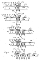
- 3b shows a case for the special training, in which the punch 27a, 27b the distance of the Have double the division.
- FIGS. 4 a to e This case is shown again in FIGS. 4 a to e.
- the Fig.4a and b correspond to what was said to Fig.3b.
- a transverse drive can 54 with which the relative position in Transverse direction between the strip material and the stamping punch, motor-driven can be changed.
- a change calls the transverse position between punch and tape material different deep recesses from the band material.
- the Band material kept at rest. Then there is a jacking step the length 59, here as a short advance referred to as.
- the length of the advance step is measured by the distance the tooth tips with the not so deep interdental space ingest t from each other.
- the depth of the interdental space is by the transverse position 55 of the toothed slide 24 set.
- the tips of the punching tools 27a, 27b are inserted Slipped out of the strip material 2, to the extent that the Except the interdental space at the required depth t becomes.
- This process creates teeth, the tips of their teeth all lie on the matching tooth tip line 61.
- the method according to FIG. 6 differs from this.
- the tape material is in the same small size Propulsion steps 56 followed by an overtaking step 57 promoted.
- the transverse position of the punch can also be used be changed.
- the tooth tip lines 61, 62 lie on different ones Levels. With each deeply retracted Stamping tool 27a, 27b or in the short advance steps tooth tips 62 are shifted back Punching tool 27a, 27b or during the long advance steps tooth tips arise on the outer tooth tip line 61 lie.
- the transverse drive 54 should accordingly be clocked.
- a connection line from the central serves this purpose Control device 21 to the motor of the transverse drive 54, the in turn geared with a transversely to the strip material 2 movable carriage is coupled.
- the timing is essential for the invention between the advance steps and the intermediate steps Propulsion rest periods. This takes place during the tunneling rest periods Stroke movement 58 of the punching slide 24. Before or after is the respective transverse position of the punch carriage 24 set by the transverse drive 54.
- the encoder is used to coordinate the timing 31, the slave 32 so after each rotational movement activated that the control device 21 a corresponding Signal can be impressed.
- the punches can also be connected to one another in one piece be and so an unchangeable stamp spacing exhibit.
Landscapes
- Engineering & Computer Science (AREA)
- Mechanical Engineering (AREA)
- Punching Or Piercing (AREA)
- Perforating, Stamping-Out Or Severing By Means Other Than Cutting (AREA)
- Control And Other Processes For Unpacking Of Materials (AREA)
Abstract
Description
Die vorliegende Erfindung betrifft eine Vorrichtung nach
Oberbegriff von Anspruch 1.The present invention relates to a device according to
Preamble of
Derartige Vorrichtungen dienen zur Herstellung von Bandsägeblättern. Hierzu werden Ausnehmungen seitlich aus dem Bandmaterial herausgestanzt. Auf diese Weise entstehen im Bandmaterial die angeschärften Zähne, welche anschließend nur noch geschränkt werden müssen.Such devices are used for the production of band saw blades. For this purpose, recesses are made laterally from the Band material punched out. In this way arise in Band material the sharpened teeth, which then only still need to be restricted.
Für die Erfindung kommt es wesentlich auf die Herstellung hochpräziser Ausnehmungen mit scharfen Kanten an, wie dies für Sägezähne erforderlich ist. Die angeschärften Sägezähne sollen in einem Arbeitsschritt allein durch Ausstanzen entstehen. Deshalb sollen im Rahmen der vorliegenden Erfindung lediglich diejenigen Vorrichtungen betrachtet werden, bei denen das Bandmaterial zum Herstellen der Ausnehmungen stillsteht. Diese Stillstandszeiten werden als Vortriebsruhezeiten bezeichnet. Das Band wird deshalb stationär gehalten, während die Ausnehmungen angebracht werden. Es erfolgt während der Vortriebsruhezeiten keine Relativbewegung zwischen dem Stanzstempel der Stanzmatrize und dem Bandmaterial in Bandlängsrichtung. Dies ist die Voraussetzung für möglichst winkelgenaue und winkelkonstante Zahnkanten bzw. Kanten der Ausnehmungen.For the invention, it depends on the production high-precision recesses with sharp edges, such as this is required for saw teeth. The sharpened saw teeth are to be cut in one step arise. Therefore, within the scope of the present invention only those devices are considered where the tape material for making the recesses stationary. These downtimes are called tunneling rest periods designated. The belt is therefore kept stationary, while the recesses are being made. It takes place during no relative movement between the tunneling rest periods the punch of the die and the tape material in Band longitudinal direction. This is the prerequisite for if possible Angular and constant tooth edges or edges of the Recesses.
Unter diesen Voraussetzungen ist aus der nicht vorveröffentlichten DE 196 14 537 eine Vorrichtung zur Herstellung von Sägezähnen an Bandmaterial bekannt, mit welcher die Ausnehmungen einzeln aus dem Bandmaterial herausgestanzt werden. Durch das einzelne Ausstanzen jedes Zahnes wird erreicht, daß jede einzelne Zahnspitze durch den nachfolgenden Stanzschritt angeschärft wird, weil der Stanzstempel die in Förderrichtung des Bandmaterials hinten liegende Zahnflanke des zuvor ausgestanzten Zahnes unter spitzem Winkel quer durchkreuzt.Under these conditions, the unpublished DE 196 14 537 a device for the production of saw teeth on strip material known with which the recesses individually from the Tape material are punched out. By punching them out individually every tooth is achieved that every single tooth tip is sharpened by the subsequent stamping step, because the punch die is in the direction of conveyance of the strip material back tooth flank of the previously punched tooth under crossed at an acute angle.
Aufgabe der vorliegenden Erfindung ist es, die bekannte Vorrichtung so weiterzubilden, daß die Geschwindigkeit bei der Herstellung der Ausnehmungen unter Beibehaltung der präzisen geometrischen Verhältnisse vervielfacht werden kann.The object of the present invention is the known Develop the device so that the speed at the production of the recesses while maintaining the precise geometric relationships can be multiplied.
Diese Aufgabe löst die Erfindung mit den Merkmalen des Hauptanspruchs.The invention solves this problem with the features of Main claim.
Aus der Erfindung ergibt sich der Vorteil, daß eine Vervielfachung der Zahnherstellungsgeschwindigkeit für Bandsägeblätter möglich wird, ohne daß die angestrebte Zahnspitzenschärfe, die sich allein durch Ausstanzen der Zähne ergibt, beeinträchtigt wird.The advantage of the invention is that multiplication the tooth production speed for band saw blades is possible without the desired tooth tip sharpness, which results only from punching out the teeth, is affected.
Gleichwohl läßt sich die Erfindung auch allgemein zur Herstellung von Ausnehmungen aus Bandmaterial verwenden. Eine Beschränkung der Erfindung auf die Herstellung von Sägezähnen ist daher nicht erforderlich.Nevertheless, the invention can also be used in general Use production of recesses from tape material. A Limitation of the invention to the manufacture of saw teeth is therefore not necessary.
Basis der Erfindung ist ein Wechsel der Schrittlängen der einzelnen Vortriebsschritte. Auf eine vorbestimmte Anzahl von Einzelschritten folgt ein sogenannter Überholschritt.The basis of the invention is a change in the stride lengths of the individual advance steps. To a predetermined number a so-called overtaking step follows from individual steps.
Die notwendige Anzahl der Einzelschritte ergibt sich aus dem Abstand, welchen die Stanzstempel voneinander einnehmen.The necessary number of individual steps results from the distance that the punches take from each other.
Da dieser sogenannte Stanzstempelabstand durch die Ausführung der Einzelschritte überwunden werden muß, wobei z.B. jeder der Einzelschritte die Schrittlänge der Teilung hat, werden in diesem Fall hierzu n-1 Vortriebsschritte benötigt. Allgemein wird durch die kleinen Vortriebsschritte das noch nicht gestanzte Bandmaterial zwischen den Stanzstempeln schrittweise mit Ausnehmungen aufgefüllt.Because this so-called punch spacing by the execution the individual steps have to be overcome, e.g. each of the individual steps has the step length of the division, In this case, n-1 advance steps are required. In general, the small advance steps make it even more so non-punched tape material between the punches gradually filled with recesses.
Zugleich jedoch wird der in Bandförderrichtung hinten liegende Stanzstempel eine identische Anzahl von Einzelschritten ausführen und dabei jeweils einen Sägezahn/eine Ausnehmung herausstanzen.At the same time, however, it is at the rear in the direction of belt conveyance lying stamps an identical number of individual steps execute and thereby one sawtooth / one Punch out the recess.
Nachdem der in Bandförderrichtung vorn liegende Stanzstempel dort angekommen ist, wo er beim nächsten Einzelschritt in einen bereits von dem in Bandförderrichtung hinten liegenden Stanzstempel herausgestanzten Zahn einfallen würde, muß der Überholschritt einsetzen.After the punch located at the front in the belt conveying direction has arrived where it is in the next step in one from the back in the direction of the belt a stamped tooth would come out, the overtaking step must begin.
Der Überholschritt hat die Schrittlänge des Stanzstempelabstands plus einmal die Schrittlänge der Teilung. In dem Überholschritt wird das Bandmaterial soweit vorangefördert, daß von dem in Bandförderrichtung vorn liegende Stanzstempel nach hinten gesehen nur noch neues, noch nicht gestanztes Bandmaterial folgt. Gleichzeitig wird auch der in Bandförderrichtung hinten liegende Stanzstempel an vorgegebener Stelle am Bandmaterial angesetzt. Es erfolgt dann die Bearbeitung eines neuen Abschnitts des Bandmaterials, nachdem der Überholschritt ausgeführt worden ist. Der gesamte Abschnitt wird jedoch an jeweils zwei Stellen gleichzeitig bearbeitet.The overtaking step has the step length of the punch spacing plus once the step length of the division. By doing Overtaking step, the belt material is advanced so far that of the punch located at the front in the belt conveying direction seen from behind only new, not yet punched Tape material follows. At the same time, that in the direction of belt conveyance punch stamps at the back at a predetermined position attached to the tape material. Processing then takes place a new section of the strip material after the overtaking step has been carried out. The entire section will but processed in two places at the same time.
Hierzu wird in einer vorbestimmten Anzahl von Einzelschritten der zwischen den Stanzstempeln befindliche Bereich des Bandmaterials durch den in Bandförderrichtung vorn liegenden Stanzstempel und den Förderweg des Bandes mit jeweils einer Schrittlänge der Teilung gestanzt. Zugleich wird jedoch auch der in Bandförderrichtung hinten liegende Stempel eine identische Anzahl von Ausnehmungen herstellen, worauf wieder ein Überholschritt erfolgen muß.This is done in a predetermined number of individual steps the area between the punches of the belt material by the one lying in front in the belt conveying direction Stamping stamp and the conveyor path of each with punched a step length of the division. At the same time, however also the stamp located at the back in the belt conveying direction create identical number of recesses, then again an overtaking step must take place.
Mit der Erfindung läßt sich folglich die Stanzgeschwindigkeit zur Herstellung der Ausnehmungen ohne Veränderung der Hubzahl pro Sekunde vervielfachen. Die Höhe der Vervielfachung hängt letztlich ab von der Anzahl der verwendeten Stempel. Die Stanzstempel können einstückig zusammenhängen. Consequently, the punching speed can be achieved with the invention to produce the recesses without changing the Multiply the number of strokes per second. The level of multiplication ultimately depends on the number of stamps used. The stamps can be connected in one piece.
Eine Weiterbildung sieht zwei Stanzstempel vor, bei denen der Stanzstempelabstand das Zweifache der Teilung ist.A further training provides two stamps, in which the punch spacing is twice the division.
Bei dieser Weiterbildung der Erfindung erfolgt wechselweise ein kurzer Vortriebsschritt, ein langer Vortriebsschritt (Überholschritt), ein kurzer Vortriebsschritt usw..This development of the invention is carried out alternately a short advance, a long advance (Overtaking step), a short advance step etc.
Die Schrittfolge ist daher abwechselnd kurz - lang - kurz - lang usw.. Durch geeignete Auswahl des Stanzstempelabstands und die kurze bzw. lange Schrittlänge können so auf einfache Weise Sägen mit Räumzähnen hergestellt werden. Die Räumzähne liegen mit ihren Zahnspitzen zurückverlegt, die Schneidzähne liegen auf der Außenkante des Bandmaterials.The sequence of steps is therefore alternately short - long - short - long etc. By suitable selection of the punch spacing and the short or long stride length can be so saws can be easily produced with teeth. The The teeth are moved back with their tooth tips Cutting teeth lie on the outer edge of the strip material.
Da bei dieser Weiterbildung periodisch praktisch abwechselnd die gleichen kinematischen Verhältnisse vorliegen, sind hiermit sehr hohe Hubzahlen von > 600 pro Minute möglich.Since in this training periodically practically alternating have the same kinematic relationships very high stroke rates of> 600 per minute are possible.
Die dynamischen Schwingungen des Systems bleiben innerhalb engster Grenzen.The system's dynamic vibrations remain within narrowest limits.
Von besonderer Bedeutung ist die Erfindung für die Herstellung von Sägezähnen. Diese werden seitlich aus einem Bandsägenblatt herausgestanzt. Hier kommt es insbesondere exakt darauf an, die Zahnspitzen scharf zu stanzen. Aus diesem Grunde ging man bisher davon aus, daß jeder Zahn für sich gestanzt werden muß.The invention is of particular importance for the production of saw teeth. These become one side Band saw blade punched out. Here it comes in particular exactly to punch the tips of the teeth sharply. For this So far, it was assumed that each tooth was for itself must be punched.
Ein Stanzwerkzeug zur unmittelbaren Herstellung zweier benachbarter Zähne in einem Stanzschritt kann diese Anforderung nicht erfüllen. Der zwischen den Stanzstempeln liegende Zahn würde nicht die erforderliche Zahnschärfe erhalten. Dies liegt daran, daß der Zwischenraum zwischen den Zahnstempeln technisch gesehen stets eine Ausrundung hätte. Die sich hieraus ergebende Zahnform würde dieser Ausrundung folgen. Dies könnte allenfalls durch anschließendes Schleifen beseitigt werden. A punching tool for the immediate production of two Adjacent teeth in one punching step can meet this requirement not meet. The one between the punches Tooth would not get the required sharpness. This is because the space between the tooth punches technically always have a fillet. The result of this resulting tooth shape would follow this fillet. This could possibly be eliminated by subsequent grinding become.
Zwar wird durch die Erfindung das bisherige Herstellverfahren, wonach die Zähne einzeln aus dem Bandmaterial herausgestanzt werden müssen, nicht verlassen. Dennoch läßt sich durch die Erfindung eine erhebliche Steigerung der Effektivität herbeiführen. Zumindest ist eine Verdopplung bei unveränderter Hubzahl des bisherigen bekannten Verfahrens möglich.Although the previous manufacturing process is after which the teeth are individually punched out of the band material must not be left. Still can by the invention a significant increase in effectiveness cause. At least a doubling is unchanged Strokes of the known method possible.
Dieser Vorteil wird durch die zwei Stanzstempel erzielt, welche einen Abstand voneinander einnehmen, der ein Vielfaches z.B. das Zweifache oder - in besonderer Ausführung - ein mehr als das Zweifache der Teilung ist.This advantage is achieved by the two stamps, which are at a distance from each other, which is a multiple e.g. twice or - in a special version - one is more than twice the division.
Damit bleiben die angestrebten Zahnspitzengeometrien bisheriger Sägezähne erhalten, während zugleich die Herstellgeschwindigkeit verdoppelt oder noch weiter vervielfacht wird.In this way, the desired tooth tip geometries remain previous saw teeth while maintaining the manufacturing speed doubled or multiplied even further becomes.
Die Verwendung lediglich zweier Stanzstempel bietet allerdings den zusätzlichen Vorteil, daß Fehlabstände und Einstelltoleranzen benachbarter Stanzstempel praktisch vermeidbar sind. Toleranzen wie bei der Verwendung von mehr als zwei Stanzstempeln treten nicht auf.However, the use of only two stamps offers the additional advantage that gaps and adjustment tolerances Adjacent punch stamp practically avoidable are. Tolerances like when using more than two Die stamps do not occur.
Eine Weiterbildung der Erfindung sieht vor, Stanzstempel und Bandmaterial relativ zueinander quer bzw. senkrecht zu den Längskanten des Bandmaterials verfahrbar zu machen.A further development of the invention provides punch stamps and tape material relative to each other across or perpendicular to to make the longitudinal edges of the strip material movable.
Im Hinblick auf die Herstellung von Bandsägen lassen sich unterschiedliche Zahnkonfigurationen damit erzielen.With regard to the production of band saws different tooth configurations can be achieved.
Sollen dann die Zahnspitzen auf einer einzigen Zahnspitzenlinie liegen, muß zusätzlich zu den unterschiedlichen Querpositionen auch der jeweilige Vortriebsschritt variiert werden.Then the tooth tips should be on a single tooth tip line must be in addition to the different Transverse positions also the respective advance step varies become.
Will man hingegen die Zahnspitzen auf voneinander unabhängige Zahnspitzenlinien legen, bedarf es nicht unbedingt einer Anpassung der Schrittlänge der Vortriebsschritte an die unterschiedlichen Querpositionen zwischen den Stanzstempeln und dem Bandmaterial. Bei konstanter Querposition kann durch unterschiedliche Schrittlängen ebenfalls erreicht werden, daß die Zahnspitzen auf unterschiedlichen Zahnspitzenlinien liegen. Ist z.B. ein Vortriebsschritt kürzer als ein Zahnabstand, wird die Spitze des soeben hergestellten vorauslaufenden Zahnes gekappt.However, if you want the tooth tips to be independent of each other Laying tooth tip lines is not absolutely necessary an adjustment of the stride length of the advance steps to the different transverse positions between the punches and the tape material. With constant transverse position can by different stride lengths can also be achieved that the tooth tips lie on different tooth tip lines. Is e.g. one advance less than one tooth gap, becomes the tip of the leading one just made Tooth capped.
Im Hinblick auf die Verwendung von Stanzstempeln, die voneinander den Abstand des Zweifachen der Teilung haben, ist von besonderer Bedeutung, daß zwischen zwei Querpositionen und zwischen einem langen und einem kurzen Vortriebsschritt jeweils gewechselt werden kann.With regard to the use of stamps that have a distance of twice the division from each other of particular importance that between two transverse positions and between a long and a short advance can be changed in each case.
Dabei entspricht der lange Vortriebsschritt dem Überholschritt, mit welchem zwei Zahnausnehmungen übersprungen werden. Mit dem kurzen Vortriebsschritt wird bei nach außen verlagerter Querposition die zwischen zwei tiefen Zahnausnehmungen liegende Bandstelle so angefahren, daß rechts und links des Stanzstempels zwei neue scharfe Zahnspitzen entstehen, die zugehörige Tiefe der Zahnausnehmung jedoch geringer ist.The long advance step corresponds to the overtaking step, with which two tooth recesses are skipped. With the short propulsion step, is shifted to the outside Transverse position between two deep tooth recesses The tape position is approached so that it is on the right and left two new sharp tooth tips are created from the punch, however, the associated depth of the tooth recess is less.
Im folgenden wird die Erfindung anhand von Ausführungsbeispielen näher erläutert. Es zeigen:
- Fig.1
- ein Ausführungsbeispiel der Erfindung in Ansicht von vorn,
- Fig.2
- ein Ausführungsbeispiel der Erfindung aus Sicht II-II gemäß Fig.1,
- Fig.3a
- ein Ausführungsbeispiel der Erfindung in allgemeiner Form,
- Fig.3b
- ein Ausführungsbeispiel der Erfindung mit Stanzstempelabstand gleich zweimal Teilung,
- Fig.4a bis 4e
- eine Folge aus Arbeitszyklen mit Darstellung des Wechsels zwischen Vortriebsschritt gleich Schrittlänge der Teilung und Überholschritt,
- Fig.5
- ein Ausführungsbeispiel für Vortriebsschritte unterschiedlicher Länge für unterschiedliche Querpositionen, und
- Fig.6
- ein Ausführungsbeispiel für Vortriebsschritte konstanter Länge bei unterschiedlichen Querpositionen.
- Fig.1
- an embodiment of the invention in front view,
- Fig.2
- an embodiment of the invention from view II-II of Figure 1,
- 3a
- an embodiment of the invention in general form,
- 3b
- an embodiment of the invention with punch spacing twice division,
- Fig.4a to 4e
- a sequence of work cycles showing the change between the advance step equal to the step length of the division and the overtaking step,
- Figure 5
- an embodiment for advance steps of different lengths for different transverse positions, and
- Figure 6
- an embodiment for tunneling steps of constant length with different transverse positions.
Sofern im folgenden nichts anderes gesagt wird, gilt die folgende Beschreibung stets für alle Figuren.Unless otherwise stated below, the following description always for all figures.
Die Figuren zeigen eine Stanzmaschine 100 zum Herausstanzen
von Ausnehmungen mit vorbestimmten und jeweils
gleichgroßen Abständen voneinander aus einem metallischen
Bandmaterial 2. Die Abstände, welche die Ausnehmungen voneinander
einnehmen, werden als Teilung 45 bezeichnet. Die Abstände
wiederholen sich regelmäßig.The figures show a punching
Wesentlich ist, daß das metallische Bandmaterial mittels
einer Bandfördereinrichtung 9 diskontinuierlich in Vortriebsschritten
vorgegebener Länge gefördert wird. Die Vortriebsschritte
haben eine Länge, die von der Teilung 45 abhängig
ist. Zwischen den Vortriebsschritten liegen jeweils sogenannte
Vortriebsruhezeiten.It is essential that the metallic strip material by means of
a belt conveyor 9 discontinuously in advance steps
given length is promoted. The advance steps
have a length that depends on the
Hierzu wird das Bandmaterial 2 von einer Abwickelspule 3
abgezogen, unter einer Stanzmatrize 14 hindurch geführt und
auf eine Aufwickelspule 4 aufgewickelt. Die Abwickelspule 3
ist hier über einen elektronisch gesteuerten Abwickelantrieb
5 in Abwickelrichtung angetrieben.For this purpose, the
Die Aufwickelspule 4 wird hier über einen ebenfalls
elektronisch geregelten Aufwickelantrieb 6 angetrieben. Abwickelantrieb
5 und Aufwickelantrieb 6 sind so eingestellt,
daß zwischen der Abwickelspule 3 und der Stanzmatrize 14 eine
vorauslaufende Verschlappungszone 7 und zwischen der Stanzmatrize
14 und der Aufwickelspule 4 eine nachlaufende Verschlappungszone
8 entsteht. Die Bandfördereinrichtung 9 weist
ein eingangsseitiges Förderrollenpaar 10 und ein ausgangsseitiges
Förderrollenpaar 11 auf. Die Förderrollenpaare 10 und
11 sind über Zugmittelantriebe 12 und 13 mit dem Bandfördermotor
22 gekoppelt, welcher ebenfalls elektronisch gesteuert
ist. The take-up
Um bei dieser Vorrichtung Vortriebsschritte vorgegebener
Länge zu realisieren, ist eine Bandwegmeßeinrichtung 15 vorgesehen,
welche mit einem Meßrad 16 auf der unteren Breitseite
17 des Bandmaterials 2 anliegt. Zur Verhinderung eines
Schlupfes zwischen Meßrad 16 und Bandmaterial 2 dient eine
dem Meßrad 16 gegenüberliegende Anpreßrolle 19, welche auf
der gegenüberliegenden Breitseite 18 anliegt. Von dem Meßrad
16 geht eine Wegsignalleitung 20 aus, welche einer Steuereinrichtung
21 zugeführt wird.In order to specify advance steps in this device
To realize length, a belt
Auf diese Weise kann das geförderte Bandmaterial jeweils
um vorbestimmte Schrittlängen vorwärts gefördert werden. Zum
Abgreifen des tatsächlich zurück gelegten Weges dient das
Meßrad 16. Da das Bandmaterial zwischen eingangsseitigem Förderrollenpaar
10 und ausgangsseitigem Förderrollenpaar 11
straff gehalten wird, sind Fehler ausgeschlossen.In this way, the conveyed strip material can
are promoted forward by predetermined stride lengths. To the
Tapping the path actually traveled serves this
Bei dem Bandfördermotor 22 handelt es sich um einen Servomotor,
der über einen Servoverstärker 23 angesteuert wird.The
Zwischen den Vortriebsschritten liegt wie gesagt jeweils
eine Vortriebsruhezeit. In den Vortriebsruhezeiten, und ausschließlich
in diesen, wenn in Bandlängsrichtung keine Relativbewegung
zwischen Stanzstempeln und Band erfolgt, werden
mittels Stanzstempel 27a bzw. 27b die Ausnehmungen in das
Bandmaterial eingebracht.As mentioned, there is always a difference between the advance steps
a jacking rest period. During tunneling rest periods, and exclusively
in these if there is no relative movement in the longitudinal direction of the strip
between stamps and tape
by means of
Zu diesem Zweck sitzen die Stanzstempel 27a und 27b an
einem gemeinsamen Zahnschlitten 24, der senkrecht zu dem
Bandmaterial 2 derart getaktet angetrieben ist, daß in den
Vortriebsruhezeiten die Stanzstempel 27a,27b mit ihren Stanzenden
in das darunter liegende Bandmaterial 2 eintauchen.For this purpose the
Hierzu ist der Zahnschlitten 24 über eine vertikale
Wälzlagerführung 26 im Maschinengehäuse 25 verschieblich gelagert.
Zur Auf- und Abbewegung dient ein Zahnschlittenexenter
29, der über einen elektronisch angesteuerten Stanzmotor
30 immer dann für eine Umdrehung in Bewegung gesetzt wird,
wenn der Bandfördermotor still steht. Dies erfolgt nach einer
bestimmten Gesetzmäßigkeit, auf die noch eingegangen wird. To this end, the
In jedem Fall liegt dieser Gesetzmäßigkeit ein getakteter Antrieb der Stanzmatrize zugrunde, der immer dann einsetzt, wenn das Bandmaterial nicht voran gefördert wird.In any case, this regularity is a timed one Drive of the punch die, which always starts if the tape material is not advanced.
Ferner sind noch von Bedeutung ein mit dem Zahnschlittenexenter
29 verbundener Geber 31 und ein ortsfester Nehmer
32, der von dem Geber 31 initialisiert wird. Das Signal des
Nehmers 32 wird der Steuereinrichtung 21 aufgegeben und dient
der Koordination zwischen den aufeinander folgenden Bandförderschritten
und den Hubbewegungen 58 des Zahnschlittens 24.Also important are those with the toothed slide eccentric
29
Um die prinzipielle Querposition zwischen dem Bandmaterial
und dem Zahnschlitten vorzugeben, dient eine Basisplatte
33, die über ein Verstellrad 39 quer zum Zahnschlitten 24
verstellt werden kann.The basic transverse position between the strip material
and to specify the toothed slide, a base plate is used
33, which crosses the
Auf der Basisplatte 33 sitzt ein Bandrückenanschlag 34,
gebildet durch zwei ortsfeste Wälzlager. An den Außenringen
der Wälzlager 35,36 liegt das Bandmaterial 2 mit der glatten
Rückenseite an, während die gegenüberliegende Parallelkante
mit den Zähnen versehen wird.On the
Es ist auch ein wesentliches Merkmal dieser Erfindung,
daß das Bandmaterial 2 mit dem gerad verlaufenden Bandrücken
am Bandrückenanschlag 34 geführt wird. Dies ermöglicht eine
präzise Einhaltung der Zahnspitzenlinie im Bereich von
1/500ste1 Millimeter und weniger, weil die gerad verlaufende
Außenkante des Bandmaterials 2 ständig und ununterbrochen an
dem Bandrückenanschlag 34 geführt wird.It is also an essential feature of this invention,
that the
Um dies zu gewährleisten, sind die eingangsseitigen und
ausgangsseitigen Förderrollenpaare 10 bzw. 11 um einen bestimmten
Neigungswinkel 44 zur Längsmittellinie des Bandmaterials
2 so geneigt, daß sich außer der Förderkraft 47 auch
eine in Richtung zum Bandrückenanschlag weisende Anpreßkraft
48 ergibt.To ensure this, the input and
output conveyor roller pairs 10 and 11 around a certain
Inclination angle 44 to the longitudinal center line of the
Zur genauen Einstellung der Querposition zwischen den
Stanzstempeln 27a,27b und dem Bandmaterial 2 dient ein Verstellrad
39, welches über eine Verstellspindel 38 eine Bewegung
der Basisplatte 33 in Verstellrichtung 37 ermöglicht. Zu
diesem Zweck ist die Verstellspindel 38 in einer Spindellagerung
40 ortsfest gelagert und greift mit ihrem Spindelgewinde
41 in ein Gegengewinde der Basisplatte 33 ein.For precise adjustment of the transverse position between the
Stamping
Seitlich ist die Basisplatte 33 an einer Längsführung 42
parallel geführt. Über die jeweilige Drehstellung der Verstellspindel
38 ergibt sich somit die Grundposition der Basisplatte
33.The
Wesentlich ist nun, daß zwei Stanzstempel 27a,27b vorgesehen
sind, welche parallel zu den Längskanten des Bandmaterials
2 liegen und welche voneinander den Abstand eines hier:
ganzzahligen Vielfachen der Teilung haben.It is now essential that two
Dieser Abstand wird als Stanzstempelabstand 49 bezeichnet.
Beide Stanzstempel 27a,27b haben identisches Profil.This distance is referred to as
Um mit einer derartigen Konfiguration die Ausnehmungen
aus dem Bandmaterial herzustellen, ist die Bandfördereinrichtung
9 derart gesteuert, daß nach einer vorbestimmten Anzahl
von kleinen Vortriebsschritten 56 mit der jeweiligen Schrittlänge
der Teilung ein Überholschritt 57 ausgeführt wird, dessen
Schrittlänge gleich ist einem vorbestimmten anderen Vielfachen
der Teilung. Hierzu ist maßgeblich der Stanzstempelabstand.
Bezeichnet man den Abstand der Stanzstempel 27a,27b
als ein n-faches der Teilung, so muß die Bandfördereinrichtung
9 zunächst n-1 Vortriebsschritte ausführen, jeden der
Vortriebsschritte mit der Schrittlänge der Teilung. Damit
wird der zwischen den Stanzstempeln liegende Bandbereich
schrittweise mit Ausnehmungen aufgefüllt. Anschließend erfolgt
der Überholschritt.To the recesses with such a configuration
To manufacture from the strip material is the strip conveyor
9 controlled such that after a predetermined number
of small advance steps 56 with the respective step length
the division an overtaking
Der Überholschritt hat dann eine Schrittlänge, die gleich ist dem (n+1)-fachen der Teilung.The overtaking step then has a stride length that is equal to (n + 1) times the division.
Es erfolgt daher ein stetiger Wechsel zwischen einer vorbestimmten Anzahl kurzer Vortriebsschritte mit einem einzigen Überholschritt großer Schrittlänge. Hierauf wird noch eingegangen.There is therefore a constant change between one predetermined number of short advance steps with a single Overtaking stride of large stride length. This will still be received.
Wie ferner die Fig.1 und 2 zeigen, muß die jeweilige
Teilung 45 auch der Steuereinrichtung 21 als Sollwert aufgeprägt
werden.As further shown in Fig.1 and 2, the
Ferner ist es erforderlich, den sogenannten Stanzstempelabstand
49 der Steuereinrichtung 21 aufzugeben, damit hieraus
die einzelnen kurzen Vortriebsschritte generiert werden
können.It is also necessary to use the so-called
Darüber hinaus ist vorgesehen, der Steuereinrichtung 21
einen weiteren Sollwert aufzugeben, der analog zur jeweiligen
Querposition 53 besteht. Hiermit ist praktisch die Eintauchtiefe
gemeint, welche von den Spitzen der Zahnstempel 27a,27b
in das Bandmaterial 2 realisiert wird.In addition, the
Da die Eintauchtiefe - synonym die Querposition 53 - und
die Geometrie der Stanzstempel 27a,27b über die Schrittlänge
der jeweiligen Vortriebsschritte miteinander in funktionalem
Zusammenhang stehen, ist diese Größe ebenfalls der Steuereinrichtung
21 aufzugeben.Since the immersion depth - synonymously the transverse position 53 - and
the geometry of the
Gemäß Fig.1 bis 6 sind jeweils 2 Stanzstempel 27a,27b an
einer einzigen Stanzmatrize angeordnet. Wie Fig.1 und 2 zeigen,
kann der Stanzstempelabstand 49 einstellbar sein. Hierzu
sind exemplarisch Langlöcher 50,51 vorgesehen, die in den
Zahnschlitten 24 eingelassen sind. Zur Befestigung der Stanzstempel
27a,27b dienen Hammerschrauben 52, welche die Langlöcher
50 hintergreifen.According to FIGS. 1 to 6, there are 2
Darüber hinaus zeigt Fig.2, daß der Zahnschlitten 24
über einen Querantrieb 54 quer zum Bandmaterial 2 verfahrbar
ist. Es ist demnach die Querposition 53 über eine Querbewegung
55, welche dem Zahnschlitten 24 vom Querantrieb 54 aufgeprägt
wird, variierbar.2 shows that the toothed slide 24th
Movable across a
Die Variation der Querposition kann von Stanzvorgang zu Stanzvorgang erfolgen. In diesem Falle würde für jede folgende Hubbewegung eine unterschiedliche Querposition anzufahren sein.The variation of the transverse position can vary from punching to Punching process. In this case, for each of the following To move to a different transverse position his.
Die unterschiedlichen Querpositionen können allerdings auch nach anderen Gesetzmäßigkeiten angefahren werden.The different transverse positions can, however can also be approached according to other laws.
Anhand von Fig.3a soll das allgemeine Prinzip der Erfindung noch einmal verdeutlicht werden.The general principle of the invention is to be explained with reference to FIG. 3a be clarified again.
In diesem Fall haben die Stanzstempel 27a und 27b einen
Abstand voneinander, welcher dem n-fachen der Teilung entspricht.
Die Teilung t ist hier die Länge der Strecke zwischen
zwei aufeinander folgenden Zähnen, die mit 45 bezeichnet
ist. Das in Förderrichtung 46 vorausgehende Stanzwerkzeug
27b hat demnach einen Abstand von dem in Förderrichtung nacheilenden
Stanzwerkzeug 27a von n-1 mal Teilung. Aus diesem
Grunde muß das Bandmaterial 2 insgesamt n-1 Vortriebsschritte
erfahren, von denen jeder Vortriebsschritt die Schrittlänge
der Teilung t aufweist. Ist dann das in Bandförderrichtung 46
vorauslaufende Stanzwerkzeug 27b an derjenigen Stelle angelangt,
wo in der gezeigten Darstellung die Vorderkante des in
Bandförderrichtung nacheilenden Stanzwerkzeugs 27a liegt, muß
das Bandmaterial 2 um insgesamt n+1 mal der Schrittlänge der
Teilung vorangefördert werden, damit das in Bandförderrichtung
vorn liegende Stanzwerkzeug 27b wieder mit einem neuen
Arbeitszyklus beginnen kann. Werden kürzere Vortriebsschritte
ausgeführt, so kann erreicht werden, daß die Zahnspitzen der
dazwischen liegenden Zähne zurückspringen, weil jeweils von
dem eintauchenden Zahnstempel gekappt.In this case, the
In Fig.3b ist ein Fall für die spezielle Ausbildung gezeigt,
in welcher die Stanzstempel 27a,27b den Abstand des
Zweifachen der Teilung haben.3b shows a case for the special training,
in which the
Wie hierzu näher aufgeführt ist, werden mit einem Stanzvorgang
die Zahnzwischenräume I und III zugleich hergestellt.
Hierauf muß ein kurzer Vortriebsschritt erfolgen, dessen
Schrittlänge die Teilung 45 ist. Dann würden die jetzt mit II
und IV bezeichneten Stellen unter den Stanzstempeln 27a,27b
liegen und im nächsten Stanzvorgang herausgestanzt. As detailed in this, are with a punching process
the interdental spaces I and III are produced at the same time.
This must be followed by a short advance step
Stride the division is 45. Then they would now with II
and IV designated positions under the
Hernach müßte die jetzt mit III' bezeichnete Stelle unter
den vorauslaufenden Stanzstempel 27b verbracht werden, wo
sich der Vorgang wiederholt.After that, the position now marked III 'should be under
the leading
Dieser Fall ist in Fig.4a bis e erneut dargestellt. Die Fig.4a und b entsprechen dem zu Fig.3b Gesagten.This case is shown again in FIGS. 4 a to e. The Fig.4a and b correspond to what was said to Fig.3b.
Zwischen den Fig.4a und 4b ist ein Vortriebsschritt 56
erfolgt, dessen Schrittlänge der Teilungslänge 45 entspricht.
Danach erfolgt ein Überholschritt 57, um den Beginn des noch
nicht gestanzten Bandmaterials unter den vorauslaufenden
Stanzstempel 27b zu bringen.There is a
Nachdem die Ausnehmungen I' und III' erstellt worden
sind, muß erneut ein Vortriebsschritt 56 kurzer Länge erfolgen
um die Ausnehmungen II' und IV' herzustellen.After the recesses I 'and III' have been created
are again a short-
Danach muß wieder ein Überholschritt 57 ausgeführt werden,
um das nächste Paar von Ausnehmungen herzustellen.An overtaking
Wie bereits anhand von Fig.2 erläutert, kann ein Querantrieb 54 vorgesehen sein, mit welchem die Relativposition in Querrichtung zwischen Bandmaterial und Stanzstempel motorisch-getrieblich verändert werden kann.As already explained with reference to FIG. 2, a transverse drive can 54 with which the relative position in Transverse direction between the strip material and the stamping punch, motor-driven can be changed.
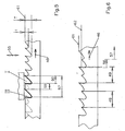
Wie anhand von Fig.5 ersichtlich, ruft eine Veränderung der Querposition zwischen Stanzstempeln und Bandmaterial unterschiedlich tiefe Ausnehmungen aus dem Bandmaterial hervor.As can be seen from Fig. 5, a change calls the transverse position between punch and tape material different deep recesses from the band material.
Es entstehen daher im Falle von Bandsägeblättern Zahnungen unterschiedlicher Zahntiefen. Dies kann Sinn machen bei sogenannten Gruppenverzahnungen.Therefore, in the case of band saw blades, serrations occur different tooth depths. This can make sense at so-called group gears.
Da infolge der unterschiedlichen Eintauchtiefe jedoch trotzdem für exakt spitze Ausbildung der Zahnspitze zu sorgen ist, müssen die Vortriebsschritte unterschiedlich lang sein bzw. so angepaßt werden, daß ausgeprägte scharfe Zahnspitzen entstehen. However, due to the different immersion depth to ensure that the tip of the tooth is precisely pointed the advance steps must be of different lengths or adjusted so that pronounced sharp tooth tips arise.
Für die Herstellung der Ausnehmungen I und III wird das
Bandmaterial in Ruhe gehalten. Danach erfolgt ein Vortriebsschritt
der Länge 59, der hier als kurzer Vortriebsschritt
bezeichnet wird.For the production of the recesses I and III, the
Band material kept at rest. Then there is a jacking step
the
Die Länge des Vortriebsschritts bemißt sich an dem Abstand,
den die Zahnspitzen mit dem nicht so tiefen Zahnzwischenraum
t voneinander einnehmen. Die Tiefe des Zahnzwischenraumes
wird durch die Querposition 55 des Zahnschlittens
24 eingestellt.The length of the advance step is measured by the distance
the tooth tips with the not so deep interdental space
ingest t from each other. The depth of the interdental space
is by the
Hierzu werden die Spitzen der Stanzwerkzeuge 27a,27b ein
Stück aus dem Bandmaterial 2 herausgefahren, soweit, daß der
Zahnzwischenraum in der erforderlichen Tiefe t ausgenommen
wird.For this purpose, the tips of the
Anschließend muß wieder ein Vortriebsschritt größerer Länge erfolgen, damit erneut ein Zahnzwischenraum großer Tiefe T entsteht.Subsequently, a further advance must be made Length so that there is again a space between the teeth of great depth T arises.
Hierzu setzt der Überholschritt 57 ein, dessen Länge der
Summe aus kurzem Zahnabstand 59 und langem Zahnabstand 60 sowie
einem zusätzlich langen Zahnabstand 60 entspricht, womit
insgesamt 3-mal (=n+1) eine zugehörige Zahnbreite überfahren
wird.For this purpose, the overtaking
In der Zwischenzeit wird der Zahnschlitten 24 erneut um
das Maß T-t in das Bandmaterial 2 hineingefahren, so daß erneut
ein Zahnzwischenraum von großer Tiefe T herausgestanzt
werden kann.In the meantime, the
Bei diesem Verfahren entstehen Zähne, deren Zahnspitzen
alle auf übereinstimmender Zahnspitzenlinie 61 liegen.This process creates teeth, the tips of their teeth
all lie on the matching
Hiervon unterscheidet sich das Verfahren gemäß Fig.6. In
diesem Fall wird das Bandmaterial in jeweils gleichen kleinen
Vortriebsschritten 56 gefolgt von einem Überholschritt 57 gefördert.
Dabei kann zusätzlich die Querposition der Stanzstempel
geändert werden. The method according to FIG. 6 differs from this. In
In this case, the tape material is in the same small size
Propulsion steps 56 followed by an overtaking
In jedem Fall liegen die Zahnspitzenlinien 61,62 auf unterschiedlichen
Niveaus. Bei jeweils tief eingefahrenem
Stanzwerkzeug 27a,27b bzw. bei den kurzen Vortriebsschritten
entstehen zurückverlagerte Zahnspitzen 62. Bei jeweils ausgefahrenem
Stanzwerkzeug 27a,27b bzw. bei den langen Vortriebsschritten
entstehen Zahnspitzen, die auf der äußeren Zahnspitzenlinie
61 liegen.In any case, the
Zur Automatisierung dieses Vorgangs kann es deshalb Sinn machen, daß die Schrittlängen der Vortriebsschritte in Abhängigkeit von den unterschiedlichen Querpositionen (T,t) der Ausnehmungen variierbar sind. Im Falle der Fig.6 ist die Schrittlänge aller Vortriebsschritte unabhängig von den unterschiedlichen Querpositionen (T,t) der Ausnehmungen.It can therefore make sense to automate this process make the stride lengths of the advance steps dependent of the different transverse positions (T, t) of the Recesses are variable. In the case of Fig.6 is the Stride length of all advance steps regardless of the different Transverse positions (T, t) of the recesses.
Ist der Zahnstempelabstand 49 - wie in den Fig.5 und 6 -, das Zweifache der Teilung, wird zwischen jeweils zwei Querpositionen T,t lediglich im Falle der Fig.5 zwischen einem langen und einem kurzen Vortriebsschritt gewechselt.Is the tooth punch distance 49 - as in Figures 5 and 6 -, twice the division, is between two Transverse positions T, t only in the case of Figure 5 between one long and a short advance step.
Darauf folgt ein Überholschritt, der so bemessen ist,
daß der Anfang noch nicht gestanzten Bandes unter den in Förderrichtung
46 vorauslaufenden Stanzstempel zu liegen kommt.This is followed by an overtaking step sized
that the beginning of the not yet punched tape under the in the conveying
Insbesondere um Zahnzwischenräume unterschiedlicher
Querpositionen T,t herzustellen, soll der Querantrieb 54 entsprechend
getaktet sein.In particular, different between tooth spaces
To produce transverse positions T, t, the
Hierzu dient eine Verbindungsleitung von der zentralen
Steuereinrichtung 21 an den Motor des Querantriebs 54, der
seinerseits getrieblich mit einem quer zum Bandmaterial 2
verfahrbaren Schlitten gekoppelt ist.A connection line from the central serves this
Wesentlich für die Erfindung ist die zeitliche Taktung
zwischen den Vortriebsschritten und den dazwischen liegenden
Vortriebsruhezeiten. In den Vortriebsruhezeiten erfolgt die
Hubbewegung 58 des Stanzschlittens 24. Vorher bzw. nachher
wird gegebenenfalls die jeweilige Querposition des Stanzschlittens
24 vom Querantrieb 54 eingestellt. The timing is essential for the invention
between the advance steps and the intermediate steps
Propulsion rest periods. This takes place during the tunneling rest
Um die Steuerung zeitlich zu koordinieren, dient der Geber
31, der nach jeweils einer Drehbewegung den Nehmer 32 so
aktiviert, daß der Steuereinrichtung 21 ein entsprechendes
Signal aufgeprägt werden kann.The encoder is used to coordinate the
Die Stanzstempel können auch einstückig miteinander verbunden sein und so einen unveränderbaren Stanzstempelabstand aufweisen. The punches can also be connected to one another in one piece be and so an unchangeable stamp spacing exhibit.
- 100100
- Stanzmaschinepunching machine
- 22
- Bandmaterialband material
- 33
- Abwickelspulereel
- 44
- Aufwickelspuleup reel
- 55
- Aufwickelantriebwinding drive
- 66
- AbwickelantriebAbwickelantrieb
- 77
- vorauslaufende Verschlappungszoneleading dumping zone
- 88th
- nachlaufende Verschlappungszonetrailing dumping zone
- 99
- BandfördereinrichtungBelt conveyor
- 1010
- eingangsseitiges Förderrollenpaarpair of feed rollers on the input side
- 1111
- ausgangsseitiges Förderrollenpaarpair of output rollers
- 1212
- Zugmittelantrieb für 10Traction drive for 10
- 1313
- Zugmittelantrieb für 11Traction drive for 11
- 1414
- Stanzmatrizepunch die
- 1515
- Bandwegmeßeinrichtungstrip path
- 1616
- Meßradmeasuring wheel
- 1717
- Breitseitebroadside
- 1818
- gegenüberliegende Breitseiteopposite broadside
- 1919
- Anpreßrollepressure roller
- 2020
- WegsignalleitungWegsignalleitung
- 2121
- Steuereinrichtungcontrol device
- 2222
- BandfördermötorBandfördermötor
- 2323
- Servoverstärkerservo
- 2424
- Zahnschlittentooth slides
- 2525
- Maschinengehäusemachine housing
- 2626
- Wälzlagerführungroller bearing guide
- 27a27a
- Stanzstempelpunch
- 27b27b
- Stanzstempelpunch
- 2828
- Gegenplattecounterplate
- 2929
- ZahnschlittenexenterZahnschlittenexenter
- 3030
- Stanzmotorpunching motor
- 3131
- Gebergiver
- 3232
- Nehmertaker
- 3333
- Basisplatte baseplate
- 3434
- BandrückenanschlagBand back stop
- 3535
- Wälzlager.Roller bearing.
- 3636
- Wälzlagerroller bearing
- 3737
- Verstellrichtungadjustment
- 3838
- Verstellspindeladjusting spindle
- 3939
- Verstellradadjustment wheel
- 4040
- Spindellagerungspindle bearing
- 4141
- Spindelgewindespindle thread
- 4242
- Längsführunglongitudinal guide
- 4343
- Drehachse der FörderrolleAxis of rotation of the conveyor roller
- 4444
- Neigungswinkeltilt angle
- 4545
- Teilungdivision
- 4646
- Förderrichtungconveying direction
- 4747
- Förderkraftconveying force
- 4848
- Anpreßkraftcontact pressure
- 4949
- StanzstempelabstandPunch distance
- 5050
- LanglochLong hole
- 5151
- LanglochLong hole
- 5252
- Hammerschraubehammer screw
- 5353
- Querpositiontransverse position
- 5454
- Querantriebtransverse drive
- 5555
- Querbewegungtransverse movement
- 5656
- Vortriebsschritt mit TeilungslängePropulsion step with pitch length
- 5757
- ÜberholschrittÜberholschritt
- 5858
- Hubbewegung des ZahnschlittensStroke movement of the tooth slide
- 5959
- Zahnspitzenabstand, kurzTooth tip distance, short
- 6060
- Zahnspitzenabstand, langTooth tip distance, long
- 6161
- Zahnspitzenlinie, außenliegendeTooth tip line, external
- 6262
- Zahnspitzenlinie, innenliegendeTooth tip line, internal
- T, tT, t
- Tiefe des jeweiligen ZahnzwischenraumsDepth of the respective interdental space
- I - IVI - IV
- Zahnzwischenraum eines ÜberholschrittsInterdental space of an overtaking step
- I' - IV'I '- IV'
- Zahnzwischenraum des nächsten ÜberholschrittsInterdental space of the next overtaking step
- I" - IV''I "- IV ''
- Zahnzwischenraum des übernächsten ÜberholschrittsInterdental space of the next but one overtaking step
Claims (9)
- Apparatus for producing endless saw blades by punching out individual, scarfed saw teeth, which are of a predetermined width and are disposed in each case at repeating intervals from each other, from a metal sheet material (2), which material is advanced by means of a sheet conveying device (9) intermittently in forward steps of predetermined lengths which depend upon the division (45) and is provided with scarfed saw teeth exclusively in the forwards movement idle times by means of a stamping punch of a punch die (14) which is driven in cycles and moves transversely with respect to the sheet material (2), wherein the scarfing is achieved by virtue of the step of punching out the following tooth, characterised in that1.0 two stamping punches (27a, 27b) which are provided on the punch die lie in parallel with the longitudinal edges of the sheet material (2) and1.1 have a spaced disposition (49) with respect to each other which is an integral multiple (n≥2) of the division (45), and that1.2 the sheet conveying device (9) after performing a number (n-1) of small forward steps, of which each is equal to the step length of the division (45),1.2.1 performs an overtaking step, the step length of which is equal to (n+1) times the division (45).
- Apparatus according to claim 1, characterised in that the two stamping punches (27a, 27b) sit on a single punch die (14).
- Apparatus according to claim 2, characterised in that the two stamping punches (27a, 27b) are connected to each other to form one piece.
- Apparatus according to claim 2, characterised in that the spacing (49) between the stamping punches can be adjusted.
- Apparatus according to any one of claims 1 to 4, characterised in that the stamping punches (27a, 27b) and sheet material (2) can be moved, for the purpose of achieving different transverse positions (53) of the cutouts, in a transverse manner relative to each other, preferably perpendicularly with respect to the longitudinal edges of the sheet material (2).
- Apparatus according to claim 5, characterised in that the step length (45) of the forward steps can be varied in dependence upon the different transverse positions (T, t) of the cutouts.
- Apparatus according to claim 5, characterised in that the step length (45) of the forward steps remains constant irrespective of the different transverse positions (T, t) of the cutouts.
- Apparatus according to claim 6, characterised in that the stamping punch spacing (49) is twice the length of the division (45) and that a change is made in each case between two transverse positions (T, t) and between a long (60) and a short (59) forward step, following which an overtaking step (57) is performed.
- Apparatus according to any one of claims 1 to 8, characterised in that the step length of the forward step is varied such that without changing the transverse position of the punching tool the tooth peaks produced lie on different tooth peak lines (61, 62).
Applications Claiming Priority (3)
| Application Number | Priority Date | Filing Date | Title |
|---|---|---|---|
| DE19739605A DE19739605A1 (en) | 1997-09-09 | 1997-09-09 | Device for punching out recesses |
| DE19739605 | 1997-09-09 | ||
| PCT/EP1998/005740 WO1999012687A1 (en) | 1997-09-09 | 1998-09-09 | Device for producing band saw blades |
Publications (2)
| Publication Number | Publication Date |
|---|---|
| EP1011908A1 EP1011908A1 (en) | 2000-06-28 |
| EP1011908B1 true EP1011908B1 (en) | 2002-01-30 |
Family
ID=7841793
Family Applications (1)
| Application Number | Title | Priority Date | Filing Date |
|---|---|---|---|
| EP98951371A Expired - Lifetime EP1011908B1 (en) | 1997-09-09 | 1998-09-09 | Device for producing band saw blades |
Country Status (4)
| Country | Link |
|---|---|
| EP (1) | EP1011908B1 (en) |
| AT (1) | ATE212579T1 (en) |
| DE (2) | DE19739605A1 (en) |
| WO (1) | WO1999012687A1 (en) |
Families Citing this family (7)
| Publication number | Priority date | Publication date | Assignee | Title |
|---|---|---|---|---|
| RU2312744C2 (en) * | 2005-09-13 | 2007-12-20 | Закрытое акционерное общество "Инструмент" (ЗАО "Инструмент") | Method and die set for forming saw teeth (variants) |
| CN103042273B (en) * | 2013-01-28 | 2015-04-29 | 东莞市萨浦刀锯有限公司 | Precise full-automatic band saw tooth punching unit |
| CN108213319A (en) * | 2018-01-19 | 2018-06-29 | 湖州众诚链传动制造厂 | A kind of safe punching apparatus of inside plank of chain |
| JP7368295B2 (en) * | 2020-03-31 | 2023-10-24 | 本田技研工業株式会社 | Method for manufacturing a fuel cell separator and apparatus for manufacturing a fuel cell separator |
| SE544496C2 (en) * | 2020-07-15 | 2022-06-21 | Swealand Hus & Fasadteknik Ab | Method and apparatus for refurbishing an oscillating multi-tool blade |
| CN112170960B (en) * | 2020-09-04 | 2022-06-21 | 南京灵雀智能制造有限公司 | Saw blade manufacturing device |
| CN112475460A (en) * | 2020-11-17 | 2021-03-12 | 东台艺新科技有限公司 | Continuous saw blade tooth pressing machine |
Family Cites Families (5)
| Publication number | Priority date | Publication date | Assignee | Title |
|---|---|---|---|---|
| US3540317A (en) * | 1967-12-12 | 1970-11-17 | Capewell Mfg Co | Method of making saw blades |
| SE452564B (en) * | 1983-02-07 | 1987-12-07 | Santrade Ltd | CASE AND WAY TO MAKE IT SAME |
| DE4010875A1 (en) * | 1989-07-24 | 1991-10-02 | Jakob Spiegeler | Process for prodn. of saw blades - has alternate teeth blanked out in two steps of strip through tool to reduce cutting force |
| SE500675C2 (en) * | 1992-10-28 | 1994-08-08 | Jan Lundh | Process for producing saw blades, wherein the blank or tool is angled between each operation, and saw blades produced according to the method |
| DE19614537A1 (en) * | 1996-04-12 | 1997-10-16 | Hans Robert Haas | Device for punching saw teeth out of a strip material |
-
1997
- 1997-09-09 DE DE19739605A patent/DE19739605A1/en not_active Withdrawn
-
1998
- 1998-09-09 DE DE59802976T patent/DE59802976D1/en not_active Expired - Lifetime
- 1998-09-09 WO PCT/EP1998/005740 patent/WO1999012687A1/en not_active Ceased
- 1998-09-09 AT AT98951371T patent/ATE212579T1/en not_active IP Right Cessation
- 1998-09-09 EP EP98951371A patent/EP1011908B1/en not_active Expired - Lifetime
Also Published As
| Publication number | Publication date |
|---|---|
| DE59802976D1 (en) | 2002-03-14 |
| EP1011908A1 (en) | 2000-06-28 |
| DE19739605A1 (en) | 1999-03-18 |
| ATE212579T1 (en) | 2002-02-15 |
| WO1999012687A1 (en) | 1999-03-18 |
Similar Documents
| Publication | Publication Date | Title |
|---|---|---|
| DE69916850T2 (en) | METHOD AND DEVICE FOR CUTTING DISCRETE COMPONENTS FROM A MULTI-COMPONENT WORKPIECE AND THEIR REGISTER-RELATED ATTACHMENT ON A CONTINUOUS MATERIAL | |
| DE102005062860A1 (en) | Method and device for producing bent spring elements | |
| DE2411980C2 (en) | Cutting device | |
| EP3673570B1 (en) | Manufacturing installation for producing a winding bar for an electric motor, and method for producing the winding bar | |
| EP1286794B1 (en) | Cold rolling machine | |
| CH701519B1 (en) | Method and apparatus for the manufacture of band saw blades. | |
| EP1011908B1 (en) | Device for producing band saw blades | |
| DE19549387C2 (en) | Rotary to linear motion conversion mechanism | |
| DE69103033T2 (en) | Method and device for cutting pipes. | |
| DE3243625C2 (en) | Punching device for producing rows of holes on the circumference of a pipe | |
| DE2315171A1 (en) | Continuous roller stamp for strip - has longitudinal and transverse cutting rolls with common back pressure roll | |
| DE2215075C2 (en) | Equipment for the production of corner and edge fittings for boxes | |
| EP0800885B1 (en) | Device for punching of saw teeth in band material | |
| DE3115506C2 (en) | ||
| DE2553059C3 (en) | Method and device for grinding cup core halves made of ferrite | |
| DE2539157B2 (en) | Punch press or the like. Machine tool | |
| DE3201401C2 (en) | ||
| DE19837036A1 (en) | Edge-banding machine to apply edging material with integral fastener rib has quick-change connector for spindle drive, adhesive applicator with guide for rib, pressure, transporter, and counter pressure rollers | |
| DE19518166C2 (en) | Punching device with at least two punching tools | |
| DE1527922B2 (en) | FEED DEVICE ON AN AUTOMATIC PUNCHING AND BENDING MACHINE | |
| DE2823737C2 (en) | Device for continuously perforating the wall of thin-walled corrugated pipes, in particular drainage pipes | |
| DE19620597C2 (en) | Device for processing sheet material | |
| DE926424C (en) | Method and device for the production of cutouts in metal strips or bands | |
| DE3924788A1 (en) | Mfr. method for saw-blades - involves cutting steel strip along zigzag longitudinal line to make two blades | |
| DE2649554A1 (en) | DEVICE FOR THE MANUFACTURING OF OBJECTS FROM A PLATE MATERIAL, IN PARTICULAR OBJECTS THAT HAVE A CONSTANT PROFILE OVER THEIR OVERALL LENGTH |
Legal Events
| Date | Code | Title | Description |
|---|---|---|---|
| PUAI | Public reference made under article 153(3) epc to a published international application that has entered the european phase |
Free format text: ORIGINAL CODE: 0009012 |
|
| 17P | Request for examination filed |
Effective date: 20000309 |
|
| AK | Designated contracting states |
Kind code of ref document: A1 Designated state(s): AT CH DE FR GB LI NL SE |
|
| GRAG | Despatch of communication of intention to grant |
Free format text: ORIGINAL CODE: EPIDOS AGRA |
|
| 17Q | First examination report despatched |
Effective date: 20010504 |
|
| GRAG | Despatch of communication of intention to grant |
Free format text: ORIGINAL CODE: EPIDOS AGRA |
|
| GRAH | Despatch of communication of intention to grant a patent |
Free format text: ORIGINAL CODE: EPIDOS IGRA |
|
| GRAH | Despatch of communication of intention to grant a patent |
Free format text: ORIGINAL CODE: EPIDOS IGRA |
|
| GRAA | (expected) grant |
Free format text: ORIGINAL CODE: 0009210 |
|
| REG | Reference to a national code |
Ref country code: GB Ref legal event code: IF02 |
|
| AK | Designated contracting states |
Kind code of ref document: B1 Designated state(s): AT CH DE FR GB LI NL SE |
|
| REF | Corresponds to: |
Ref document number: 212579 Country of ref document: AT Date of ref document: 20020215 Kind code of ref document: T |
|
| REG | Reference to a national code |
Ref country code: CH Ref legal event code: EP |
|
| REG | Reference to a national code |
Ref country code: CH Ref legal event code: NV Representative=s name: E. BLUM & CO. PATENTANWAELTE |
|
| REF | Corresponds to: |
Ref document number: 59802976 Country of ref document: DE Date of ref document: 20020314 |
|
| GBT | Gb: translation of ep patent filed (gb section 77(6)(a)/1977) |
Effective date: 20020407 |
|
| ET | Fr: translation filed | ||
| PLBE | No opposition filed within time limit |
Free format text: ORIGINAL CODE: 0009261 |
|
| STAA | Information on the status of an ep patent application or granted ep patent |
Free format text: STATUS: NO OPPOSITION FILED WITHIN TIME LIMIT |
|
| 26N | No opposition filed | ||
| REG | Reference to a national code |
Ref country code: CH Ref legal event code: PFA Owner name: HAAS, HANS ROBERT Free format text: HAAS, HANS ROBERT#EMILIENSTRASSE 56#42853 REMSCHEID (DE) -TRANSFER TO- HAAS, HANS ROBERT#EMILIENSTRASSE 56#42853 REMSCHEID (DE) |
|
| PGFP | Annual fee paid to national office [announced via postgrant information from national office to epo] |
Ref country code: CH Payment date: 20080908 Year of fee payment: 11 |
|
| PGFP | Annual fee paid to national office [announced via postgrant information from national office to epo] |
Ref country code: NL Payment date: 20080917 Year of fee payment: 11 Ref country code: AT Payment date: 20080912 Year of fee payment: 11 |
|
| PGFP | Annual fee paid to national office [announced via postgrant information from national office to epo] |
Ref country code: GB Payment date: 20080910 Year of fee payment: 11 |
|
| PGFP | Annual fee paid to national office [announced via postgrant information from national office to epo] |
Ref country code: SE Payment date: 20080908 Year of fee payment: 11 |
|
| PGFP | Annual fee paid to national office [announced via postgrant information from national office to epo] |
Ref country code: FR Payment date: 20080930 Year of fee payment: 11 |
|
| REG | Reference to a national code |
Ref country code: NL Ref legal event code: V1 Effective date: 20100401 |
|
| REG | Reference to a national code |
Ref country code: CH Ref legal event code: PL |
|
| EUG | Se: european patent has lapsed | ||
| GBPC | Gb: european patent ceased through non-payment of renewal fee |
Effective date: 20090909 |
|
| REG | Reference to a national code |
Ref country code: FR Ref legal event code: ST Effective date: 20100531 |
|
| PG25 | Lapsed in a contracting state [announced via postgrant information from national office to epo] |
Ref country code: AT Free format text: LAPSE BECAUSE OF NON-PAYMENT OF DUE FEES Effective date: 20090909 |
|
| PG25 | Lapsed in a contracting state [announced via postgrant information from national office to epo] |
Ref country code: NL Free format text: LAPSE BECAUSE OF NON-PAYMENT OF DUE FEES Effective date: 20100401 Ref country code: FR Free format text: LAPSE BECAUSE OF NON-PAYMENT OF DUE FEES Effective date: 20090930 |
|
| PG25 | Lapsed in a contracting state [announced via postgrant information from national office to epo] |
Ref country code: LI Free format text: LAPSE BECAUSE OF NON-PAYMENT OF DUE FEES Effective date: 20090930 Ref country code: CH Free format text: LAPSE BECAUSE OF NON-PAYMENT OF DUE FEES Effective date: 20090930 |
|
| PG25 | Lapsed in a contracting state [announced via postgrant information from national office to epo] |
Ref country code: GB Free format text: LAPSE BECAUSE OF NON-PAYMENT OF DUE FEES Effective date: 20090909 |
|
| PG25 | Lapsed in a contracting state [announced via postgrant information from national office to epo] |
Ref country code: SE Free format text: LAPSE BECAUSE OF NON-PAYMENT OF DUE FEES Effective date: 20090910 |
|
| PGFP | Annual fee paid to national office [announced via postgrant information from national office to epo] |
Ref country code: DE Payment date: 20121130 Year of fee payment: 15 |
|
| REG | Reference to a national code |
Ref country code: DE Ref legal event code: R119 Ref document number: 59802976 Country of ref document: DE Effective date: 20130403 |
|
| PG25 | Lapsed in a contracting state [announced via postgrant information from national office to epo] |
Ref country code: DE Free format text: LAPSE BECAUSE OF NON-PAYMENT OF DUE FEES Effective date: 20130403 |