EP0985573B1 - Öffnungs- und Schliessvorrichtung für den Ladedeckel eines elektrischen Fahrzeugs - Google Patents
Öffnungs- und Schliessvorrichtung für den Ladedeckel eines elektrischen Fahrzeugs Download PDFInfo
- Publication number
- EP0985573B1 EP0985573B1 EP99117672A EP99117672A EP0985573B1 EP 0985573 B1 EP0985573 B1 EP 0985573B1 EP 99117672 A EP99117672 A EP 99117672A EP 99117672 A EP99117672 A EP 99117672A EP 0985573 B1 EP0985573 B1 EP 0985573B1
- Authority
- EP
- European Patent Office
- Prior art keywords
- rotary member
- charging lid
- charging
- electric vehicle
- coupler
- Prior art date
- Legal status (The legal status is an assumption and is not a legal conclusion. Google has not performed a legal analysis and makes no representation as to the accuracy of the status listed.)
- Expired - Lifetime
Links
Images


Classifications
-
- B—PERFORMING OPERATIONS; TRANSPORTING
- B60—VEHICLES IN GENERAL
- B60L—PROPULSION OF ELECTRICALLY-PROPELLED VEHICLES; SUPPLYING ELECTRIC POWER FOR AUXILIARY EQUIPMENT OF ELECTRICALLY-PROPELLED VEHICLES; ELECTRODYNAMIC BRAKE SYSTEMS FOR VEHICLES IN GENERAL; MAGNETIC SUSPENSION OR LEVITATION FOR VEHICLES; MONITORING OPERATING VARIABLES OF ELECTRICALLY-PROPELLED VEHICLES; ELECTRIC SAFETY DEVICES FOR ELECTRICALLY-PROPELLED VEHICLES
- B60L53/00—Methods of charging batteries, specially adapted for electric vehicles; Charging stations or on-board charging equipment therefor; Exchange of energy storage elements in electric vehicles
- B60L53/30—Constructional details of charging stations
- B60L53/305—Communication interfaces
-
- B—PERFORMING OPERATIONS; TRANSPORTING
- B60—VEHICLES IN GENERAL
- B60L—PROPULSION OF ELECTRICALLY-PROPELLED VEHICLES; SUPPLYING ELECTRIC POWER FOR AUXILIARY EQUIPMENT OF ELECTRICALLY-PROPELLED VEHICLES; ELECTRODYNAMIC BRAKE SYSTEMS FOR VEHICLES IN GENERAL; MAGNETIC SUSPENSION OR LEVITATION FOR VEHICLES; MONITORING OPERATING VARIABLES OF ELECTRICALLY-PROPELLED VEHICLES; ELECTRIC SAFETY DEVICES FOR ELECTRICALLY-PROPELLED VEHICLES
- B60L53/00—Methods of charging batteries, specially adapted for electric vehicles; Charging stations or on-board charging equipment therefor; Exchange of energy storage elements in electric vehicles
- B60L53/30—Constructional details of charging stations
- B60L53/35—Means for automatic or assisted adjustment of the relative position of charging devices and vehicles
- B60L53/38—Means for automatic or assisted adjustment of the relative position of charging devices and vehicles specially adapted for charging by inductive energy transfer
-
- B—PERFORMING OPERATIONS; TRANSPORTING
- B60—VEHICLES IN GENERAL
- B60L—PROPULSION OF ELECTRICALLY-PROPELLED VEHICLES; SUPPLYING ELECTRIC POWER FOR AUXILIARY EQUIPMENT OF ELECTRICALLY-PROPELLED VEHICLES; ELECTRODYNAMIC BRAKE SYSTEMS FOR VEHICLES IN GENERAL; MAGNETIC SUSPENSION OR LEVITATION FOR VEHICLES; MONITORING OPERATING VARIABLES OF ELECTRICALLY-PROPELLED VEHICLES; ELECTRIC SAFETY DEVICES FOR ELECTRICALLY-PROPELLED VEHICLES
- B60L53/00—Methods of charging batteries, specially adapted for electric vehicles; Charging stations or on-board charging equipment therefor; Exchange of energy storage elements in electric vehicles
- B60L53/60—Monitoring or controlling charging stations
- B60L53/67—Controlling two or more charging stations
-
- Y—GENERAL TAGGING OF NEW TECHNOLOGICAL DEVELOPMENTS; GENERAL TAGGING OF CROSS-SECTIONAL TECHNOLOGIES SPANNING OVER SEVERAL SECTIONS OF THE IPC; TECHNICAL SUBJECTS COVERED BY FORMER USPC CROSS-REFERENCE ART COLLECTIONS [XRACs] AND DIGESTS
- Y02—TECHNOLOGIES OR APPLICATIONS FOR MITIGATION OR ADAPTATION AGAINST CLIMATE CHANGE
- Y02T—CLIMATE CHANGE MITIGATION TECHNOLOGIES RELATED TO TRANSPORTATION
- Y02T10/00—Road transport of goods or passengers
- Y02T10/60—Other road transportation technologies with climate change mitigation effect
- Y02T10/70—Energy storage systems for electromobility, e.g. batteries
-
- Y—GENERAL TAGGING OF NEW TECHNOLOGICAL DEVELOPMENTS; GENERAL TAGGING OF CROSS-SECTIONAL TECHNOLOGIES SPANNING OVER SEVERAL SECTIONS OF THE IPC; TECHNICAL SUBJECTS COVERED BY FORMER USPC CROSS-REFERENCE ART COLLECTIONS [XRACs] AND DIGESTS
- Y02—TECHNOLOGIES OR APPLICATIONS FOR MITIGATION OR ADAPTATION AGAINST CLIMATE CHANGE
- Y02T—CLIMATE CHANGE MITIGATION TECHNOLOGIES RELATED TO TRANSPORTATION
- Y02T10/00—Road transport of goods or passengers
- Y02T10/60—Other road transportation technologies with climate change mitigation effect
- Y02T10/7072—Electromobility specific charging systems or methods for batteries, ultracapacitors, supercapacitors or double-layer capacitors
-
- Y—GENERAL TAGGING OF NEW TECHNOLOGICAL DEVELOPMENTS; GENERAL TAGGING OF CROSS-SECTIONAL TECHNOLOGIES SPANNING OVER SEVERAL SECTIONS OF THE IPC; TECHNICAL SUBJECTS COVERED BY FORMER USPC CROSS-REFERENCE ART COLLECTIONS [XRACs] AND DIGESTS
- Y02—TECHNOLOGIES OR APPLICATIONS FOR MITIGATION OR ADAPTATION AGAINST CLIMATE CHANGE
- Y02T—CLIMATE CHANGE MITIGATION TECHNOLOGIES RELATED TO TRANSPORTATION
- Y02T90/00—Enabling technologies or technologies with a potential or indirect contribution to GHG emissions mitigation
- Y02T90/10—Technologies relating to charging of electric vehicles
- Y02T90/12—Electric charging stations
-
- Y—GENERAL TAGGING OF NEW TECHNOLOGICAL DEVELOPMENTS; GENERAL TAGGING OF CROSS-SECTIONAL TECHNOLOGIES SPANNING OVER SEVERAL SECTIONS OF THE IPC; TECHNICAL SUBJECTS COVERED BY FORMER USPC CROSS-REFERENCE ART COLLECTIONS [XRACs] AND DIGESTS
- Y02—TECHNOLOGIES OR APPLICATIONS FOR MITIGATION OR ADAPTATION AGAINST CLIMATE CHANGE
- Y02T—CLIMATE CHANGE MITIGATION TECHNOLOGIES RELATED TO TRANSPORTATION
- Y02T90/00—Enabling technologies or technologies with a potential or indirect contribution to GHG emissions mitigation
- Y02T90/10—Technologies relating to charging of electric vehicles
- Y02T90/14—Plug-in electric vehicles
-
- Y—GENERAL TAGGING OF NEW TECHNOLOGICAL DEVELOPMENTS; GENERAL TAGGING OF CROSS-SECTIONAL TECHNOLOGIES SPANNING OVER SEVERAL SECTIONS OF THE IPC; TECHNICAL SUBJECTS COVERED BY FORMER USPC CROSS-REFERENCE ART COLLECTIONS [XRACs] AND DIGESTS
- Y02—TECHNOLOGIES OR APPLICATIONS FOR MITIGATION OR ADAPTATION AGAINST CLIMATE CHANGE
- Y02T—CLIMATE CHANGE MITIGATION TECHNOLOGIES RELATED TO TRANSPORTATION
- Y02T90/00—Enabling technologies or technologies with a potential or indirect contribution to GHG emissions mitigation
- Y02T90/10—Technologies relating to charging of electric vehicles
- Y02T90/16—Information or communication technologies improving the operation of electric vehicles
Definitions
- the present invention relates to a charging lid opening and closing device for protecting a receiving coupler on an electric vehicle which is powered by electric energy supplied from a battery.
- Electric vehicles are powered by electric energy stored in and supplied from batteries mounted thereon.
- the battery on an electric vehicle needs to be charged with electric energy from an external source from time to time.
- the electric vehicle has a receiving coupler that can be fitted over an energy supplying coupler of an electric energy supply station.
- the energy supplying coupler can automatically engage the receiving coupler and start automatically charging the battery through the receiving coupler, then the burden on attendants at the electric energy supply station can be minimized.
- the receiving coupler of the electric vehicle needs to be protected against dirt and dust, and requires an openable and closable lid for giving the electric vehicle a neat appearance. If the battery is to be automatically charged through the receiving coupler, then it is desirable that the openable and closable lid should automatically be opened and closed.
- gasoline-powered vehicles have a fuel inlet lid that is manually openable and closable for supplying gas oline to the gasoline tank. Users of electric vehicles are usually accustomed to such a manually openable and closable fuel inlet lid, and hence possibly tend to manually open and close the openable and closable lid for the receiving coupler.
- an automatically openable and closable lid for the receiving coupler is manually opened and closed, then an excessive load is liable to be imposed on a mechanism for automatically opening and closing the lid.
- a feeding coupler may not normally be fitted into the receiving coupler, and if the lid is not fully closed, then the lid may wobble as it is partially open, and possibly adversely affect the way in which the electric vehicle runs.
- JP 10 152071 A discloses a pivotable lid of a motor vehicle covering a socket, in which a plug can be plugged.
- US-A-5,443,292 discloses a lock mechanism for finally closing and initially opening a trunk lid of a vehicle.
- the lid has to be closed manually until only a little a gap is left between an edge of the lid and an edge of the trunk opening.
- a vehicle mounted striker of a lid drawing mechanism catches the lock mechanism of the lid and draws the trunk lid into a fully closed position by electric power.
- the catching and drawing of the trunk lid is achieved by a rotatably driven excentric cam guided in a long arcuate cam slot of the striker base plate.
- a major object of the present invention is to provide a charging lid opening and closing device which allows a charging lid to automatically switch from a manually opening and closing mode to an automatically opening and closing mode.
- Another object of the present invention is to provide a charging lid opening and closing device which can shorten a motor idling time when a charging lid switches from a manually opening and closing mode to an automatically opening and closing mode.
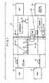
- FIG. 1 schematically shows an electric vehicle sharing system which incorporates the principles of the present invention.
- the electric vehicle sharing system shown in FIG. 1 is a system for allowing a plurality of users to share a plurality of electric vehicles 10.
- the electric vehicle sharing system covers an area 12 where the users can drive the available electric vehicles 10.
- the area 12 is combined with a plurality of ports 13 where a plurality of electric vehicles 10 can be parked.
- a user i.e., a driver, rents an electric vehicle 10 from a port 13 near the driver's house or company, drives the electric vehicle 10 from the port 13 to a nearby station or supermarket, for example, accomplishes whatever the purpose may be, and thereafter returns the electric vehicle 10 to a nearby port 13.
- the area 12 contains a plurality of communication means 14 for transmitting and receiving information relative to the status of usage of the electric vehicles 10 by way of suitable communications. The received information is sent from the communication means 14 to a central facility 16 of the electric vehicle sharing system.
- FIG. 2 schematically shows in plan structural details of each of the ports 13.
- the port 13 comprises a platform 18 where users rent and return electric vehicles 10, and a plurality of parking areas 19 for pooling a plurality of electric vehicles 10.
- the platform 18 has a port terminal control unit 20 for performing vehicle renting and returning processes. Specifically, a user rents a desired electric vehicle 10 or returns a used electric vehicle 10, using an IC (Integrated Circuit) card storing usage information, etc., at the port terminal control unit 20.
- IC Integrated Circuit
- Induction cables 22 and magnetic nails 24 are embedded in each of the ports 13 along routes between the platform 18 and the parking areas 19, for automatically driving the electric vehicles 10.
- One of the parking areas 19 is associated with a battery charging apparatus 26 for charging the battery on an electric vehicle 10 that is parked in the parking area 19.
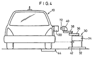
- FIGS. 3 and 4 show the battery charging apparatus 26 and an electric vehicle 10 parked in the parking area 19 which is equipped with the battery charging apparatus 26.
- the battery charging apparatus 26 comprises a charger 28 for supplying electric energy based on a charging command signal from the electric vehicle 10 and stopping the supply of electric energy based on a charging completion signal from the electric vehicle 10, and a battery charging robot 30 connected to the charger 28 for automatically charging the battery on the electric vehicle 10.
- the battery charging robot 30 comprises a robot body 34 mounted on a base 32, a first arm 36 having an end pivotally supported on the robot body 34, a second arm 38 having an end pivotally supported on the other end of the first arm 36, and a feeding coupler 40 angularly movably supported on the other end of the second arm 38.
- the robot body 34 is vertically movable along a Y-axis, which is perpendicular to other horizontal X- and Z-axes, and the first arm 36 and the second arm 38 are swingable about respective axes on the robot body 34 and the first arm 36. Therefore, the feeding coupler 40 angularly movably supported on the end of the second arm 38 can be displaced three-dimensionally along X-, Y-, and Z-axes.
- An ultrasonic sensor 42 for detecting a distance from a receiving coupler 118 of the electric vehicle 10 along the Z-axis is mounted on the base 32 of the battery charging robot 30.
- the parking area 19 also has a tire tread force sensor 44 for detecting the position of the electric vehicle 10 along the X- and Z-axes based on the placement of a rear wheel of the electric vehicle 10 on the tire tread force sensor 44.
- the tire tread force sensor 44 may be replaced with a CCD camera or the like for detecting the positions of the electric vehicle 10 along the X- and Z-axes.
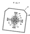
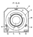
- FIGS. 5 through 8 show structural details of the feeding coupler 40 of the battery charging robot 30.
- the feeding coupler 40 is mounted on the end of the second arm 38 by a first bracket 46.
- a second bracket 52 To the first bracket 46, there is coupled a second bracket 52 by two pins 48, 50 for displacement along the X-axis, i.e., directions normal to the sheets of FIGS. 5 and 6.
- the second bracket 52 has an integral sleeve 53 extending horizontally and including an intermediate portion which has a prismatic outer shape.
- a shaft 54 is axially slidably inserted in the sleeve 53.
- the sleeve 53 has an open end positioned remotely from the first bracket 46 and shaped into a skirt 56 having a circular outer contour.
- a stop pin 60 is coupled by a plate 58 to an end of the shaft 54 which passes through the second bracket 52.
- the stop pin 60 engages in a hole 62 defined in the first bracket 46, the feeding coupler 40 is prevented from being displaced along the X-axis.
- a limit switch 63 for detecting axial displacement of the shaft 54 is disposed near the end of the shaft 54 which is close to the first bracket 46.
- a ball 64 is mounted on the other end of the shaft 54, with a collar 66 mounted on the shaft 54 against the ball 64.
- a helical spring 68 is disposed around the shaft 54 between the skirt 56 and the collar 66.
- the feeding coupler 40 has a coupler body 72 angularly movably supported on the ball 64 on the end of the shaft 54 by a bearing 70.
- the coupler body 72 comprises a bracket 73 supporting the bearing 70, a core 74 joined to the bracket 73, and a feeding coil 76 wound around a block of the core 74 which projects toward the electric vehicle 10.
- the bracket 73 has a hollow cylindrical central member which holds therein a doughnut-shaped stop ring 78 engaging the skirt 56 of the second bracket 52.
- To the bracket 73 there is connected a holder 75 which holds therein four springs 80, 82, 84, 86 extending radially and angularly positioned at equal angular intervals.
- the springs 80, 82, 84, 86 have respective radially inner ends held against respective outer surfaces of the intermediate portion of the sleeve 53 which has the prismatic outer shape.
- the feeding coupler 40 also has a casing 88 surrounding the components thereof.
- Three locking hooks 92 are angularly movably mounted by shafts 90 on an inner surface of the casing 88 near the electric vehicle 10.
- the locking hooks 92 are held in locking engagement with the electric vehicle 10 when the battery on the electric vehicle 10 is charged by the battery charging robot 30.
- the locking hooks 92 which are angularly movable about the shafts 90, are normally urged in a direction to keep locking engagement with the electric vehicle 10 by springs 94 acting between the bracket 73 and ends of the locking hooks 92.
- the feeding coupler 40 has, on its surface facing the electric vehicle 10, a pair of light-emitting and -detecting elements 96 for confirming the position of the electric vehicle 10 with respect to the battery charging robot 30, and a pair of light-emitting and -detecting elements 98 for exchanging various signals with respect to the charging of the battery, e.g., receiving a charging command signal and a charging completion signal from the electric vehicle 10.
- FIG. 9 shows an electric system, including a control circuit, of the battery charging robot 30.
- the control circuit has a charging robot controller 99 for controlling operation of the battery charging robot 30, and a charging controller 101 for controlling the charging of the battery based on control signals from the electric vehicle 10.
- the ultrasonic sensor 42, the tire tread force sensor 44, and the light-emitting and -detecting elements 96 are connected to the charging robot controller 99 for controlling operation of the robot body 34, the first arm 36, and the second arm 38.
- the charger 28, the charging coil 76, and the light-emitting and -detecting elements 98 are connected to the charging controller 101.
- the electric vehicle 10 that can automatically be charged by the battery charging apparatus 26 is constructed as shown in FIG. 10.
- the electric vehicle 10 comprises a vehicle control ECU 100 for controlling entire operation of the electric vehicle 10 including vehicle driving operation and battery charging operation, a battery 102 for storing electric energy for propelling the electric vehicle 10, and an electric motor 104 for propelling the electric vehicle 10 based on the electric energy supplied from the battery 102.
- a communication unit 106 for performing communication with an external circuit
- a brake controller 108 and a steering controller 110 for automatically driving the electric vehicle 10
- the sensors 112, 114 serve to detect a magnetic field generated by an alternating current flowing through an induction cable 22 (see FIG. 2), and are laterally spaced along the rear axle of the electric vehicle 10. When the electric vehicle 10 runs along and over an induction cable 22, the sensors 112, 114 produce identical output signals. When the electric vehicle 10 is laterally displaced, one of the sensors 112, 114 produces an output signal greater than the output signal produced by the other of the sensors 112, 114, detecting that the electric vehicle 10 does not run properly along a desired route.
- the sensor 116 serves to detect a magnetic field generated by magnets (magnetic nails 24) embedded along a route.
- the sensor 116 generates an output signal the instant the electric vehicle 10 passes over a magnetic nail 24.
- the sensor 116 is also displaced laterally from the longitudinal central axis of the electric vehicle 10, as shown in FIG. 10.
- the induction cables 22 only have a function to detect when the electric vehicle 10 is laterally displaced off the route.
- the magnetic nails 24 have a function to accurately detect a position of the electric vehicle 10 in its direction of travel, e.g., a position where the electric vehicle 10 stops.
- the magnetic nails 24 are also used in an auxiliary manner in the case where a route defined by an induction cable 22 is abruptly curved.
- the sensors 112, 114, 116 serve to detect a magnetic field, they should preferably be installed on the electric vehicle 10 in positions away from magnetic bodies in order to avoid magnetic disturbance. For example, it is preferable to employ attachment members of synthetic resin for attaching the sensors 112, 114, 116 in position. Moreover, because the electric vehicle 10 suffers different radii of curvature of paths traced by outer wheels when it makes a turn, the sensors 112, 114, 116 are positioned along the axle of the rear wheels, rather than the steerable wheels (front wheels), and the electric vehicle 10 is controlled with the axle of the rear wheels as a target for the route, for thereby increasing the accuracy with which the electric vehicle 10 is to follow a desired trajectory when automatically driven.
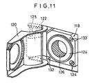
- the electric vehicle 10 has a receiving coupler 118 for charging the battery 102 with the battery charging apparatus 26, and a charging lid opening and closing device 122 for opening and closing a charging lid 120 which covers the receiving coupler 118.
- the receiving coupler 118 comprises a receiving coil 126 wound around a core 124 and connected to the battery 102 through a rectifier 127 and a contactor 129 (see FIG. 10).
- the core 124 has reflectors 132, 133 for reflecting a light signal from the light-emitting and -detecting elements 96 on the core 74 of the feeding coupler 40, and light-emitting and -detecting elements 134 for sending a light signal to and receiving a light signal from the light-emitting and -detecting elements 98.
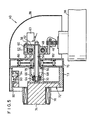
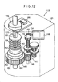
- the charging lid opening and closing device 122 is constructed as shown in FIGS. 12 and 13.
- the charging lid opening and closing device 122 has a casing 123 surrounding its components, and a rotatable shaft 125 having opposite ends projecting out of the casing 123.
- Stays 131, 135 connected to the charging lid 120 by brackets 128, 130 are joined to the respective opposite ends of the rotatable shaft 125.
- the casing 123 houses therein an electric motor 138 which rotates a drive shaft 136 based on a command signal for opening and closing the charging lid 120 which is supplied from the vehicle control ECU 100.
- a worm 140 mounted on the drive shaft 136 is held in mesh with a worm wheel 142 to which there is coupled a gear train 144 as a speed reducer comprising a plurality of intermeshing gears having different diameters.
- the gear train 144 has a final gear 146 held in mesh with outer gear teeth of a base plate 148.
- the rotatable shaft 125 connected to the charging lid 120 is rotatably inserted centrally through the base plate 148.
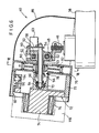
- the base plate 148 has a plurality of grooves 150 defined in one surface thereof around the central axis of the base plate 148, with balls 152 engaging in the respective grooves 150.
- a slide collar 154 is fitted over the rotatable shaft 125 in axially confronting relation to the base plate 148. The slide collar 154 engages an engagement surface 156 of the rotatable shaft 125 and is displaceable in the axial direction of the rotatable shaft 125.
- a collar 157 is fixedly mounted on the rotatable shaft 125 in axially spaced relation to the slide collar 154.
- a helical spring 159 is disposed around the rotatable shaft 125 between the collar 157 and the slide collar 154 for normally biasing the slide collar 154 away from the collar 157.
- the slide collar 154 has a plurality of engagement recesses 158 defined in a surface thereof facing the base plate 148, the engagement recesses 158 being positioned in regions corresponding to the grooves 150 and regions between the grooves 150.
- the balls 152 are engageable in the engagement recesses 158.
- Each of the engagement recesses 158 is of a conical shape for allowing one of the balls 152 to engage therein and disengage therefrom.
- a dog 164 is fixedly mounted on the rotatable shaft 125.
- a charging lid opening and closing sensor 166 is housed in and fixed to the casing 123 for detecting an angular displacement of the dog 164 caused by the rotatable shaft 125.
- the electric vehicle 10, the battery charging apparatus 26, and the charging lid opening and closing device 122 are basically constructed as described above. Operation of the electric vehicle 10, the battery charging apparatus 26, and the charging lid opening and closing device 122 will be described below.
- a user checks ID information based on an IC card, for example, with the port terminal control unit 20 at the platform 18 of any arbitrary port 13, and selects an electric vehicle 10.
- the selected electric vehicle 10 is automatically driven to the platform 18 by being guided by the induction cable 22 and the magnetic nails 24 in the parking area 19.
- the electric vehicle 10 has the sensors 112, 114 that are symmetrically positioned along the rear wheel axle.
- the vehicle control ECU 100 controls the steering controller 110 in order to equalize the intensities, detected by the sensors 112, 114, of a magnetic field that is generated by a current flowing through the induction cable 22, for thereby guiding the electric vehicle 10 along the induction cable 22 to the platform 18.
- the vehicle control ECU 100 Based on the intensities of magnetic fields generated by the magnetic nails 24 detected by the sensor 116, the vehicle control ECU 100 detects the position of the electric vehicle 10 in the direction of travel. When the electric vehicle 10 arrives at the platform 18, the vehicle control ECU 100 controls the brake controller 108 to stop the electric vehicle 10.
- the automatic driving mode of the electric vehicle 10 is canceled. Thereafter, the user gets on the electric vehicle 10 and manually drives the electric vehicle 10 to a destination.
- the user gets off the electric vehicle 10 at the platform 18 of any arbitrary port 13, and then operates the port terminal control unit 20 to return the electric vehicle 10 in step S1.
- the electric vehicle 10 is automatically driven to a position (charging port) where the battery charging apparatus 26 is located in the parking area 19 in step S2.
- the electric vehicle 10 is controlled using the induction cable 22 and the magnetic nails 24 in the parking area 19, in the same manner as when the electric vehicle 10 is rented.
- the charging port has the battery charging apparatus 26 and the tire tread force sensor 44 for detecting the position of the electric vehicle 10.
- the tire tread force sensor 44 detects whether the rear wheels of the electric vehicle 10 are positioned within predetermined ranges along the X- and Z-axes with respect to the battery charging apparatus 26, in step S3.
- the battery charging apparatus 26 decides whether the electric vehicle 10 is in a fitting position where the feeding coupler 40 of the battery charging apparatus 26 can be fitted in the receiving coupler 118 of the electric vehicle 10 in step S4. If the electric vehicle 10 is not in the fitting position, then the position where the electric vehicle 10 is stopped with respect to the charging port is adjusted in step S5. Thereafter, the processing in steps S3, S4 is repeated.
- step S4 If the electric vehicle 10 is in the fitting position in step S4, then the charging lid 120 of the electric vehicle 10 is automatically opened in step S6. A control process for opening and closing the charging lid 120 will be described below with reference to FIG. 17.
- the vehicle control ECU 100 When the vehicle control ECU 100 receives a lid opening command signal from the battery charging apparatus 26 in step S6a, the vehicle control ECU 100 energizes the motor 138 of the charging lid opening and closing device 122 to rotate its drive shaft 136 in a direction to open the charging lid 120 in step S6b.
- the worm 140 coupled to the drive shaft 136 is rotated to cause the gear train 144, which serves as the speed reducer including the worm wheel 142 meshing with the worm 140, to rotate the base plate 148.
- the slide collar 154 is coaxially connected to the base plate 148 by the balls 152. As the slide collar 154 is rotated, the rotatable shaft 125 is rotated.
- the charging lid 120 which is connected to the rotatable shaft 125 by the brackets 128, 130 and the stays 131, 135 is opened.
- the vehicle control ECU 100 detects a drive current of the motor 138 in step S6c. If the detected drive current is greater than a predetermined value in step S6d, i.e., if the motor 138 is subjected to a load greater than a predetermined load, then the vehicle control ECU 100 determines that the charging lid 120 is fully opened, and de-energizes the motor 138 in step S6e.
- the battery charging robot 30 of the battery charging apparatus 26 is actuated to bring the feeding coupler 40 into fitting engagement with the receiving coupler 118 of the electric vehicle 10 in step S7 (see FIG. 16).
- a control process for fitting the feeding coupler 40 with the receiving coupler 118 will be described below with reference to FIG. 18.
- the ultrasonic sensor 42 on the base 32 of the battery charging robot 30 detects a distance from the battery charging robot 30 to the receiving coupler 118 in step S7a. Based on the detected distance to the receiving coupler 118, the battery charging robot 30 actuates the first arm 36 and the second arm 38 to move the feeding coupler 40 along the Z-axis toward the receiving coupler 118 in step S7b.
- the battery charging robot 30 holds the feeding coupler 40 in its position along the Z-axis, and moves the feeding coupler 40 along the X- and Y-axes in step S7c.
- the battery charging robot 30 detects reflected light beams from the reflectors 132, 133 on the receiving coupler 138 in step S7d.
- the light-emitting element 96 on the feeding coupler 40 emits a light beam toward the receiving coupler 118, and the battery charging robot 30 detects a position where a reflected light beam from the reflector 132 on the receiving coupler 118 can be detected by the light-detecting element 96.
- the battery charging robot 30 stores in memory the position of the feeding coupler 40 when the reflected light beam from the reflector 132 is detected by the light-detecting element 96 in step S7e.
- the battery charging robot 30 detects a position where a reflected light beam from the reflector 133 on the receiving coupler 118 can be detected by the light-detecting element 96.
- the battery charging robot 30 stores in memory the position of the feeding coupler 40 when the reflected light beam from the reflector 133 is detected by the light-detecting element 96 in steps S7c through S7f.
- the battery charging robot 30 calculates the position of the receiving coupler 118 in step S7g. Since the receiving coupler 118 is thus positionally detected, the feeding coupler 40 can be fitted in the receiving coupler 118 with high accuracy.
- the battery charging robot 30 Based on the position of the receiving coupler 118 calculated in step S7g, the battery charging robot 30 displaces the feeding coupler 40 along the X- and Y-axes to correct the position of the feeding coupler 40 in step S7h. Thereafter, the battery charging robot 30 actuates the first arm 36 and the second arm 38 to move the feeding coupler 40 toward the receiving coupler 118 of the electric vehicle 10 in step S7i.
- the battery charging apparatus 26 monitors whether there is a reflected light beam from the reflector 132 of the receiving coupler 118 or not at all times in step S7j.
- the battery charging robot 30 continuously moves the feeding coupler 40 until there is a reflected light beam from the reflector 132 and the feeding coupler 40 is brought into fitting engagement with the receiving coupler 118 in step S7k.
- the feeding coupler 40 is fitted into the receiving coupler 118 as follows:
- the end of the shaft 54 engages the limit switch 63, which detects the full fitting engagement of the feeding coupler 40 with the receiving coupler 118.
- the battery charging apparatus 26 Upon detection of the full fitting engagement of the feeding coupler 40 with the receiving coupler 118, the battery charging apparatus 26 stops the movement of the feeding coupler 40 in step S7m. The fitting engagement of the feeding coupler 40 with the receiving coupler 118 is now completed.
- step S7j If a reflected light beam from the reflector 132 is not detected in step S7j, then the battery charging apparatus 26 determines that an unexpected situation has occurred, e.g., a foreign object has entered between the feeding coupler 40 and the receiving coupler 118, blocking the reflected light beam, or the charging lid 120 is accidentally closed.
- the battery charging apparatus 26 returns the feeding coupler 40 to its origin, i.e., the standby position, and stops moving the feeding coupler 40 in step S7n. If a reflected light beam from the reflector 132 is not detected in step S7j, then the battery charging apparatus 26 may not return the feeding coupler 40 to its origin and stop moving the feeding coupler 40.
- the battery charging apparatus 26 may stop moving the feeding coupler 40 and then start coupling the feeding coupler 40 to the receiving coupler 118 again, or may return the feeding coupler 40 to its origin and then start coupling the feeding coupler 40 to the receiving coupler 118 again.
- step S8 a battery charging process is carried out by the battery charging robot in step S8 (FIG. 16). The battery charging process will be described below with reference to FIG. 19.
- the vehicle control ECU 100 checks a charged state of the battery 102.
- the vehicle control ECU 100 sends a charging command signal from the light-emitting element 134 on the receiving coupler 118 to the light-emitting element 98 on the feeding coupler 40 in step S8a.
- the battery charging apparatus 26 supplies a current to the feeding coil 76 of the feeding coupler 40.
- the current supplied to the feeding coil 76 generates a magnetic field which generates a current in the receiving coil 126 of the receiving coupler 118.
- the generated current is rectified by the rectifier 127 into a direct current, which is supplied via the contactor 129 made conductive by the vehicle control ECU 100 to the battery 102 for thereby charging the battery 102 in step S8b.
- the vehicle control ECU 100 checks the charged state of the battery 102 at all times. If the vehicle control ECU 100 determines that the battery 102 is fully charged, the vehicle control ECU 100 sends a charging completion signal via the light-emitting element 134 to the battery charging apparatus 26, and turns off the contactor 129 in step S8c. In response to the charging completion signal, the battery charging apparatus 26 stops supplying the current to the feeding coil 76, and the charging of the battery 102 is completed in step S8d.
- the battery charging robot 30 releases the feeding coupler 40 from the receiving coupler 118 in step S9 (see FIG. 14). A process for releasing the feeding coupler 40 from the receiving coupler 118 will be described below with reference to FIG. 20.
- the battery charging apparatus 26 detects the position of the feeding coupler 40 along the X- and Y-axes based on signals from sensors (not shown) attached to the robot body 34, the first arm 36, and the second arm 38 of the battery charging robot 30 in step S9a. While keeping the detected position of the feeding coupler 40 along the X- and Y-axes, the battery charging apparatus 26 actuates the first arm 36 and the second arm 38 to move the feeding coupler 40 along the Z-axis in step S9b. In this manner, the feeding coupler 40 can be released from the receiving coupler 118 without causing damage to the receiving coupler 118.
- the battery charging apparatus 26 moves the robot body 34, the first arm 36, and the second arm 38 to origins along the X-, Y-, and Z-axes for thereby returning the battery charging robot 30 to its origin in step S9d.
- step S10 a process for closing the charging lid 120 is carried out in step S10 (see FIG. 14).
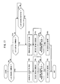
- the process for closing the charging lid 120 will be described below with reference to FIG. 17.
- the vehicle control ECU 100 If the feeding coupler 40 is sufficiently spaced from the electric vehicle 10 and the vehicle control ECU 100 supplies a lid closing command signal for closing the charging lid 120 in step S10a, then the vehicle control ECU 100 energizes the motor 138 of the charging lid opening and closing device 122 to rotate its drive shaft 136 in a direction to close the charging lid 120 in step S10b.
- the worm 140 coupled to the drive shaft 136 is rotated to cause the gear train 144 to rotate the base plate 148.
- the rotation of the base plate 148 causes the balls 152 to rotate the slide collar 154, thus rotating the rotatable shaft 125.
- the charging lid 120 is now closed.
- the vehicle control ECU 100 detects a drive current of the motor 138 in step S10c. If the detected drive current is greater than a predetermined value in step S10d, then the vehicle control ECU 100 determines that the charging lid 120 is fully closed, and de-energizes the motor 138 in step S10e.
- the charging lid 120 is opened in response to a lid opening command signal from the battery charging apparatus 26 and closed in response to a lid closing command signal from the vehicle control ECU 100.
- the charging lid 120 may be opened and closed when the user of the electric vehicle 10 operates a lid opening and closing switch.
- the charging lid 120 which is open can manually be closed forcibly. Specifically, when the user, for example, of the electric vehicle 10 displaces the charging lid 120 in a direction to close the same, the rotatable shaft 125 is rotated, rotating the slide collar 154.
- the base plate 148 operatively coupled to the slide collar 154 by the balls 152 is connected to the worm 140 by the gear train 144, the base plate 148 is locked against rotation.
- the rotatable shaft 125 causes the slide collar 154 to rotate therewith over the balls 152 and hence to move axially along the rotatable shaft 125 against the bias of the spring 159.
- the balls 152 are released out of engagement in the engagement recesses 158. Therefore, whereas the base plate 148 is held against rotation, the rotatable shaft 125 and the slide collar 154 are rotated thereby to displace the charging lid 120 in the closing direction.
- the dog 164 rotating with the rotatable shaft 125 is detected by the charging lid opening and closing sensor 166, which enables the vehicle control ECU 100 to recognize that the charging lid 120 is being closed in step S10f.
- the vehicle control ECU 100 now energizes the motor 138 to rotate its drive shaft 136 in the direction to close the charging lid 120 in step S10b.
- the base plate 148 initially rotates independently of the slide collar 154 because the balls 152 are not received in the engagement recesses 158 in the slide collar 154.
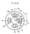
- the base plate 148 is angularly moved a certain angle ⁇ 2 (see FIG. 15)
- the balls 152 engage back into the engagement recesses 158, thus coupling the base plate 148 and the slide collar 154 to each other. Therefore, the charging lid 120 is forcibly displaced in the closing direction by the motor 138.
- the slide collar 154 has the plurality of engagement recesses 158.
- the slide collar 154 has other engagement recesses 158 at angular positions where ⁇ 2 > ⁇ 3, then after the base plate 148 is angularly moved the angle ⁇ 3, the slide collar 154 is coupled to the base plate 148. Accordingly, the charging lid 120 can be closed in a shorter idling time of the motor 138.
- the vehicle control ECU 100 detects a drive current of the motor 138 in step S10c. If the detected drive current is greater than a predetermined value in step S10d, then the vehicle control ECU 100 determines that the charging lid 120 is fully closed, and de-energizes the motor 138 in step S10e.
- the charging lid 120 can manually be closed. If the charging lid 120 is not manually closed to its fully closed position, then the motor 138 is energized to fully close the charging lid 120.
- the charging lid 120 when the charging lid 120 is closed, it automatically switches from a manually closing mode to an automatically closing mode. However, when the charging lid 120 is opened, it may automatically switch from a manually opening mode to an automatically opening mode. Specifically, when the charging lid 120 is manually opened, the charging lid opening and closing sensor 166 detects when the charging lid has been opened a predetermined angle, and then the motor 138 is energized to rotate the drive shaft 136 in a direction to open the charging lid 120. Consequently, the charging lid 120 can fully be opened after it has started to be manually closed. As a result, when the feeding coupler 40 is fitted into the receiving coupler 118, the feeding coupler 40 is prevented from physically interfering with the charging lid 120 which would otherwise be left partly open.
- the electric vehicle 10 with the charging lid 120 closed is then moved to a rental standby position in the parking area 19 in step S11.
- a charging lid (120) When a charging lid (120) is manually opened or closed, a rotatable shaft (125) is rotated thereby. At this time, a second rotary member (154) rotates about the rotatable shaft (125) and moves axially along the rotatable shaft (125). Balls (159) are released from engagement recesses (158) defined in the second rotary member (154), disengaging a first rotary member (148) from the second rotary member (154).
- the charging lid (120) can thus easily manually be opened or closed.
- a sensor (166) detects the angular displacement of the rotatable shaft (125) and outputs a detected signal. In response to the detected signal, a motor (138) is energized to rotate the rotatable shaft (125) to forcibly open or close the charging lid (120).
Landscapes
- Engineering & Computer Science (AREA)
- Power Engineering (AREA)
- Transportation (AREA)
- Mechanical Engineering (AREA)
- Electric Propulsion And Braking For Vehicles (AREA)
- Charge And Discharge Circuits For Batteries Or The Like (AREA)
- Arrangement Or Mounting Of Propulsion Units For Vehicles (AREA)
Claims (6)
- Ladedeckelöffnungs- und -schließvorrichtung (122) zum Öffnen und Schließen eines Ladedeckels (120), welcher eine Aufnahme-Kopplungseinrichtung (118) an einem elektrischen Fahrzeug (10) schützt, das durch von einer Batterie zugeführte elektrische Energie mit Energie versorgt wird, wobei der Ladedeckel (120) mit einer drehbaren Welle (125) zur gemeinsamen Drehung verbunden ist, wobei die Ladedeckelöffnungs- und -schließvorrichtung (122) umfasst:einen Motor (138), welcher in Antwort auf ein Deckelöffnungs/Schließbefehlssignal bestrombar ist, wobei der Motor (138) über eine Antriebswelle (136) eine Drehbewegung ausgibt,einen Überlastkupplungsmechanismus (148, 152, 154, 159), welcher betriebsmäßig zwischen der drehbaren Welle (125) des Ladedeckels (120) und der Antriebswelle (136) des Motors (138) angeschlossen ist und welcher dazu ausgebildet ist, eine vom Motor (138) induzierte Drehung der Antriebswelle (136) in einem normalen Betriebszustand zu der drehbaren Welle (125) zu übertragen, wobei der Überlastkupplungsmechanismus (148, 152, 154, 159) dazu ausgebildet ist, die Antriebswelle (136) und die drehbare Welle voneinander zu trennen und dadurch in einem Überlastzustand eine Drehung lediglich der drehbaren Welle (125) zu gestatten, wenn eine äußere Kraft, welche größer als ein vorbestimmtes Niveau ist, auf den Ladedeckel (120) ausgeübt wird, um den Ladedeckel (120) zu öffnen oder zu schließen;Erfassungsmittel (164, 166) zum Erfassen, wann der Ladedeckel (120) einen vorbestimmten Winkel geöffnet oder geschlossen ist, und zum Ausgeben eines Erfassungssignals; sowieSteuer/Regelmittel (100) zum Bestromen des Motors (138), um die Antriebswelle (135) in einer Richtung zum Öffnen oder Schließen des Ladedeckels (120) in Antwort auf das Erfassungssignal von den Erfassungsmitteln (164, 166) zu drehen.
- Ladedeckelöffnungs- und -schließvorrichtung nach Anspruch 1,
wobei der Kupplungsmechanismus umfasst:wobei wenigstens ein Element aus dem ersten Drehelement und dem zweiten Drehelement auf das andere Element aus dem ersten Drehelement und dem zweiten Drehelement zu und von diesem weg verlagerbar ist, wobei die Anordnung derart ist, dass die Kugeln aus einem Eingriff mit dem einen Element aus dem ersten Drehelement und dem zweiten Drehelement gelöst werden können, wenn die äußere Kraft, welche größer als das vorbestimmte Niveau ist, auf den Ladedeckel ausgeübt wird, um den Ladedeckel zu öffnen oder zu schließen.ein erstes Drehelement (148);ein zweites Drehelement (154);ein Druckelement (159), um das erste Drehelement und das zweite Drehelement gegeneinander zu drücken; sowieeine Mehrzahl von Kugeln (152), welche zwischen dem ersten Drehelement und dem zweiten Drehelement angeordnet und mit diesen in Eingriff bringbar sind, um eine Drehung des ersten Drehelements zu dem zweiten Drehelement zu übertragen; - Ladedeckelöffnungs- und -schließvorrichtung nach Anspruch 2,
wobei die drehbare Welle eine Eingriffsfläche (156) aufweist, welche durch das zweite Drehelement in Eingriff genommen ist, wobei das zweite Drehelement in axialen Richtungen der drehbaren Welle verlagerbar ist. - Ladedeckelöffnungs- und -schließvorrichtung nach Anspruch 2,
wobei wenigstens ein Element aus dem ersten Drehelement und dem zweiten Drehelement eine Mehrzahl von Eingriffsausnehmungen (158) aufweist,
wobei die Kugeln lösbar mit den Eingriffsausnehmungen in Eingriff bringbar sind, wobei die Anordnung derart ist, dass die Kugeln aus den Eingriffsausnehmungen gelöst werden können, wenn die äußere Kraft, welche größer als das vorbestimmte Niveau ist, auf den Ladedeckel ausgeübt wird, um den Ladedeckel zu öffnen oder zu schließen, und wobei die Kugeln in Eingriff mit den nächstgelegenen der Eingriffsausnehmungen gelangen können, wenn der Motor bestromt wird. - Ladedeckelöffnungs- und -schließvorrichtung nach Anspruch 4,
wobei die Eingriffsausnehmungen bei Abständen definiert sind, welche kleiner als Abstände zwischen den Kugeln sind, welche um eine Mittelachse des ersten Drehelements oder des zweiten Drehelements herum angeordnet sind. - Ladedeckelöffnungs- und -schließvorrichtung nach Anspruch 1,
wobei die Erfassungsmittel umfassen:eine Klaue (164), welche gemeinsam mit der drehbaren Welle drehbar ist; sowieeinen Sensor (166), um zu erfassen, wenn die Klaue (164) einen vorbestimmten Winkel in Winkelrichtung bewegt wurde.
Applications Claiming Priority (2)
| Application Number | Priority Date | Filing Date | Title |
|---|---|---|---|
| JP10255710A JP2000092617A (ja) | 1998-09-09 | 1998-09-09 | 電動車両における充電用リッド開閉装置 |
| JP25571098 | 1998-09-09 |
Publications (3)
| Publication Number | Publication Date |
|---|---|
| EP0985573A2 EP0985573A2 (de) | 2000-03-15 |
| EP0985573A3 EP0985573A3 (de) | 2002-03-20 |
| EP0985573B1 true EP0985573B1 (de) | 2004-09-29 |
Family
ID=17282572
Family Applications (1)
| Application Number | Title | Priority Date | Filing Date |
|---|---|---|---|
| EP99117672A Expired - Lifetime EP0985573B1 (de) | 1998-09-09 | 1999-09-07 | Öffnungs- und Schliessvorrichtung für den Ladedeckel eines elektrischen Fahrzeugs |
Country Status (4)
| Country | Link |
|---|---|
| US (1) | US6194854B1 (de) |
| EP (1) | EP0985573B1 (de) |
| JP (1) | JP2000092617A (de) |
| DE (1) | DE69920610T2 (de) |
Cited By (2)
| Publication number | Priority date | Publication date | Assignee | Title |
|---|---|---|---|---|
| CN108422876A (zh) * | 2018-02-07 | 2018-08-21 | 重庆交通职业学院 | 一种新能源汽车用充电桩 |
| CN108891292A (zh) * | 2018-07-17 | 2018-11-27 | 王志强 | 一种新能源汽车充电方法 |
Families Citing this family (39)
| Publication number | Priority date | Publication date | Assignee | Title |
|---|---|---|---|---|
| US7267015B2 (en) | 2004-09-20 | 2007-09-11 | Quantum Corporation | System and method for testing media device doors |
| US7999506B1 (en) * | 2008-04-09 | 2011-08-16 | SeventhDigit Corporation | System to automatically recharge vehicles with batteries |
| DE102008039955A1 (de) * | 2008-08-27 | 2010-03-04 | Bayerische Motoren Werke Aktiengesellschaft | Ladevorrichtung für ein Elektrofahrzeug |
| DE102009033236A1 (de) | 2009-07-14 | 2011-01-20 | Conductix-Wampfler Ag | Vorrichtung zur induktiven Übertragung elektrischer Energie |
| US10002198B2 (en) * | 2009-10-28 | 2018-06-19 | Verizon Patent And Licensing Inc. | Mobile taxi dispatch system |
| JP2011101459A (ja) * | 2009-11-04 | 2011-05-19 | Toyota Motor Corp | 移動体の電力補給用開閉扉 |
| CN103038975B (zh) | 2010-04-26 | 2016-09-14 | 普罗特拉公司 | 用于电动车在充电站自动连接和充电的系统与方法 |
| US8841881B2 (en) | 2010-06-02 | 2014-09-23 | Bryan Marc Failing | Energy transfer with vehicles |
| DE102010038570B4 (de) | 2010-07-28 | 2022-10-06 | Kiekert Aktiengesellschaft | Ladeeinrichtung für ein Elektrfahrzeug und Verfahren |
| DE102010048384A1 (de) * | 2010-10-13 | 2012-04-19 | Audi Ag | Kraftfahrzeug |
| US9308825B2 (en) * | 2011-01-19 | 2016-04-12 | Aerovironment, Inc. | Electric vehicle docking connector with embedded EVSE controller |
| DE102011005386B4 (de) * | 2011-03-10 | 2023-03-09 | Compleo Charging Solutions Ag | Lademodul und Verfahren zum Betrieb desselben |
| JP5629616B2 (ja) * | 2011-03-18 | 2014-11-26 | 株式会社東海理化電機製作所 | 給電プラグロック装置 |
| JP5635437B2 (ja) * | 2011-03-18 | 2014-12-03 | 株式会社東海理化電機製作所 | 給電プラグロック装置 |
| DE102011078386A1 (de) * | 2011-06-30 | 2013-01-03 | Robert Bosch Gmbh | Versorgesystem und Verfahren zum Versorgen eines elektrischen Verbrauchers |
| DE102011083819A1 (de) * | 2011-09-30 | 2013-04-04 | Kiekert Ag | Verriegelungseinrichtung für ein Kraftfahrzeug |
| US9327607B2 (en) * | 2013-05-10 | 2016-05-03 | GM Global Technology Operations LLC | Automated recharging system and method for an electric vehicle using RFID tags |
| GB2518128B (en) * | 2013-06-20 | 2021-02-10 | Nokia Technologies Oy | Charging rechargeable apparatus |
| JP6299659B2 (ja) * | 2014-11-13 | 2018-03-28 | トヨタ自動車株式会社 | 燃料電池を搭載した車両及びその制御方法 |
| CN106740161A (zh) * | 2015-11-20 | 2017-05-31 | 梁策初 | 电动汽车安全自动充电设备 |
| US10071645B2 (en) | 2016-02-05 | 2018-09-11 | Faraday&Future Inc. | Autonomous vehicle charging station connection |
| US10286793B2 (en) * | 2016-02-05 | 2019-05-14 | Faraday & Future Inc. | Autonomous vehicle charging station connection |
| CN106956612B (zh) * | 2017-04-04 | 2018-11-30 | 新乡市合众鑫辉车业有限公司 | 一种自控插接的新能源汽车充电桩装置 |
| DE102017109988B4 (de) * | 2017-05-09 | 2019-08-01 | Conductix-Wampfler Gmbh | Energieversorgungssystem und Verfahren zum Verbinden eines Leitungskabels mit einer Verbindungvorrichtung |
| CN107627873A (zh) * | 2017-08-30 | 2018-01-26 | 享奕自动化科技(上海)有限公司 | 电动汽车的充电盖自动翻盖装置及方法、自动充电系统及充电方法 |
| CN107776421A (zh) * | 2017-09-14 | 2018-03-09 | 胡春秀 | 一种电动汽车自动充电设备 |
| CN107839505B (zh) * | 2017-09-14 | 2019-05-10 | 台州市酷乐客车业有限公司 | 一种自动充电臂及电动汽车 |
| CN107813297A (zh) * | 2017-11-23 | 2018-03-20 | 深圳市海梁科技有限公司 | 机器人手臂及电动车充电装置 |
| SE542310C2 (en) * | 2018-01-18 | 2020-04-07 | No Picnic Ab | Charging arrangement for the charging of electrical vehicles |
| DE102018104762B4 (de) * | 2018-03-02 | 2021-08-12 | Avateramedical Digital Solutions Gmbh | Vorrichtung und Verfahren zum selbsttätigen Verbinden/Trennen eines Aufladeanschlusses mit einer Aufladeanschlussaufnahme eines Fahrzeugs |
| CN109398127B (zh) * | 2018-10-24 | 2020-07-07 | 台州狼鹰电容器制造有限公司 | 一种新能源汽车用便于自动的充电器 |
| CN109910647B (zh) * | 2019-04-18 | 2024-03-08 | 合肥有感科技有限责任公司 | 汽车无线充电地锁、汽车无线充电系统及方法 |
| CN111262294B (zh) * | 2020-02-27 | 2021-06-25 | 江苏工程职业技术学院 | 一种智能机器人充电装置及使用方法 |
| KR102421477B1 (ko) * | 2020-06-24 | 2022-07-15 | 하오 용 오토모티브 컨트롤즈 리미티드 | 자동차 충전포트도어용 액추에이터 |
| JP2022079312A (ja) * | 2020-11-16 | 2022-05-26 | トヨタ自動車株式会社 | 自動走行カート |
| CN113561814B (zh) * | 2021-08-31 | 2023-06-20 | 岚图汽车科技有限公司 | 一种汽车电动充电口盒装置 |
| CN113864403A (zh) * | 2021-10-19 | 2021-12-31 | 东莞皓永汽车配件有限公司 | 汽车的盖板驱动装置 |
| CN113954673B (zh) * | 2021-12-08 | 2024-03-15 | 深圳市卓永杭电子有限公司 | 一种便于调节的可移动式新能源充电桩及其使用方法 |
| KR20230157044A (ko) * | 2022-05-09 | 2023-11-16 | 하오 용 오토모티브 컨트롤즈 리미티드 | 서클립을 구비하는 클러치 및 이를 포함하는 차량용 커버플레이트 구동장치 |
Family Cites Families (18)
| Publication number | Priority date | Publication date | Assignee | Title |
|---|---|---|---|---|
| US5341083A (en) * | 1991-09-27 | 1994-08-23 | Electric Power Research Institute, Inc. | Contactless battery charging system |
| JPH0614408A (ja) | 1992-06-19 | 1994-01-21 | Toyota Autom Loom Works Ltd | 電気自動車用充電装置 |
| DE4322689C2 (de) * | 1992-07-08 | 1999-07-08 | Ohi Seisakusho Co Ltd | Verriegelungsvorrichtung |
| CA2141852A1 (en) * | 1992-08-07 | 1994-02-17 | Thomas Yatsko | Needleless access stopper |
| US5306999A (en) * | 1993-01-15 | 1994-04-26 | Hubbell Incorporated | Electric vehicle charging station |
| US5344331A (en) * | 1993-01-15 | 1994-09-06 | Hubbell Incorporated | Electrical connector system, especially for electric vehicles |
| US5461298A (en) * | 1993-01-15 | 1995-10-24 | Hughes Aircraft Company | Automatic electric vehicle charging system |
| JP3469276B2 (ja) * | 1993-08-30 | 2003-11-25 | アスモ株式会社 | 逆転防止軸受装置 |
| JP3252035B2 (ja) * | 1993-09-14 | 2002-01-28 | 本田技研工業株式会社 | 電気自動車の充電表示装置 |
| DE4344563C1 (de) * | 1993-12-24 | 1994-12-08 | Daimler Benz Ag | Batterieladevorrichtung für ein Elektrofahrzeug |
| US5498948A (en) * | 1994-10-14 | 1996-03-12 | Delco Electornics | Self-aligning inductive charger |
| JPH08301396A (ja) * | 1995-04-28 | 1996-11-19 | Funai Electric Co Ltd | ガソリンスタンドにおける自動課金システム |
| JPH09182212A (ja) | 1995-12-25 | 1997-07-11 | Toyota Autom Loom Works Ltd | 自動充電装置 |
| JPH09285022A (ja) * | 1996-04-10 | 1997-10-31 | Honda Motor Co Ltd | 電気自動車の充電表示装置 |
| US5847537A (en) * | 1996-10-19 | 1998-12-08 | Parmley, Sr.; Daniel W. | Electric vehicle charging station system |
| JP3266015B2 (ja) * | 1996-11-26 | 2002-03-18 | 日産自動車株式会社 | 電気自動車の充電ポートユニット取付構造 |
| US5881497A (en) * | 1997-03-10 | 1999-03-16 | Borgardt; Ronald | Automatic door opener adaptable for manual doors |
| JPH11332024A (ja) * | 1998-05-12 | 1999-11-30 | Nissan Motor Co Ltd | 電気自動車の充電リッド構造 |
-
1998
- 1998-09-09 JP JP10255710A patent/JP2000092617A/ja active Pending
-
1999
- 1999-09-07 DE DE69920610T patent/DE69920610T2/de not_active Expired - Fee Related
- 1999-09-07 EP EP99117672A patent/EP0985573B1/de not_active Expired - Lifetime
- 1999-09-08 US US09/391,512 patent/US6194854B1/en not_active Expired - Fee Related
Cited By (3)
| Publication number | Priority date | Publication date | Assignee | Title |
|---|---|---|---|---|
| CN108422876A (zh) * | 2018-02-07 | 2018-08-21 | 重庆交通职业学院 | 一种新能源汽车用充电桩 |
| CN108891292A (zh) * | 2018-07-17 | 2018-11-27 | 王志强 | 一种新能源汽车充电方法 |
| CN108891292B (zh) * | 2018-07-17 | 2021-09-17 | 杭州翔毅科技有限公司 | 一种新能源汽车充电方法 |
Also Published As
| Publication number | Publication date |
|---|---|
| EP0985573A2 (de) | 2000-03-15 |
| DE69920610D1 (de) | 2004-11-04 |
| EP0985573A3 (de) | 2002-03-20 |
| JP2000092617A (ja) | 2000-03-31 |
| DE69920610T2 (de) | 2005-02-10 |
| US6194854B1 (en) | 2001-02-27 |
Similar Documents
| Publication | Publication Date | Title |
|---|---|---|
| EP0985573B1 (de) | Öffnungs- und Schliessvorrichtung für den Ladedeckel eines elektrischen Fahrzeugs | |
| US6157162A (en) | Battery charging apparatus for electric vehicles | |
| US10604021B2 (en) | Method and apparatus for automatic charging of an electrically powered vehicle | |
| JP2000092622A (ja) | 電動車両用充電装置 | |
| US8890475B1 (en) | Automobile charging and communications station | |
| JP5377119B2 (ja) | 駐車支援システムおよび駐車支援システムの制御方法 | |
| JP4353197B2 (ja) | 車両および電気機器 | |
| EP0788212B1 (de) | Verbindungssystem und -verfahren für ein elektrisch betriebenes Fahrzeug | |
| US20110066515A1 (en) | Automated electric plug-in station for charging electric and hybrid vehicles | |
| JP5950028B2 (ja) | 非接触給電システム | |
| CN110997400A (zh) | 可交换电池系统 | |
| KR20180046600A (ko) | 전기자동차용 충전장치 및 전기자동차 충전 제어방법 | |
| JP2019165544A (ja) | 外部補給装置及び車両管理システム | |
| CN101277838A (zh) | 用于车辆与地上设备间电力发送与接收的方法以及停车辅助装置 | |
| US20190217715A1 (en) | Ev charging projector | |
| US20220258630A1 (en) | Electric Vehicle Automatic Charging Station | |
| CN113320410B (zh) | 一种用于为电动车辆提供应急充电的充电车及其工作方法 | |
| CN113997891A (zh) | 用于车辆的便携式电力系统 | |
| WO2021039778A1 (ja) | バッテリ充電モジュール、バッテリ交換装置、およびバッテリ装置 | |
| JPH1028332A (ja) | 電気自動車用充電装置 | |
| JPH09172743A (ja) | 充電装置のカプラ結合装置 | |
| WO2021039773A1 (ja) | バッテリ充電モジュール、バッテリ交換装置、およびバッテリ装置 | |
| US11660241B2 (en) | Exchangeable universal wheelchair power assist | |
| EP3533310B1 (de) | Rasenflächenmanagementsystem | |
| JP2000092619A (ja) | 電動車両用充電システム |
Legal Events
| Date | Code | Title | Description |
|---|---|---|---|
| PUAI | Public reference made under article 153(3) epc to a published international application that has entered the european phase |
Free format text: ORIGINAL CODE: 0009012 |
|
| AK | Designated contracting states |
Kind code of ref document: A2 Designated state(s): AT BE CH CY DE DK ES FI FR GB GR IE IT LI LU MC NL PT SE Kind code of ref document: A2 Designated state(s): DE FR GB IT |
|
| AX | Request for extension of the european patent |
Free format text: AL;LT;LV;MK;RO;SI |
|
| RIN1 | Information on inventor provided before grant (corrected) |
Inventor name: SHIMADA, MICHIO, C/O K.K. HONDA GIJYUTSU KENKYUSH Inventor name: SONE, TOSHIHIRO, C/O K.K. HONDA GIJYUTSU KENKYUSH Inventor name: OZAWA, AKIRA, C/O K.K. HONDA GIJYUTSU KENKYUSHO Inventor name: UCHIBORI, KENJI, C/O K.K. HONDA GIJYUTSU KENKYUSHO |
|
| PUAL | Search report despatched |
Free format text: ORIGINAL CODE: 0009013 |
|
| AK | Designated contracting states |
Kind code of ref document: A3 Designated state(s): AT BE CH CY DE DK ES FI FR GB GR IE IT LI LU MC NL PT SE |
|
| AX | Request for extension of the european patent |
Free format text: AL;LT;LV;MK;RO;SI |
|
| RIC1 | Information provided on ipc code assigned before grant |
Free format text: 7B 60L 11/18 A, 7E 05F 15/00 B |
|
| 17P | Request for examination filed |
Effective date: 20020621 |
|
| 17Q | First examination report despatched |
Effective date: 20020919 |
|
| AKX | Designation fees paid |
Free format text: DE FR GB IT |
|
| GRAP | Despatch of communication of intention to grant a patent |
Free format text: ORIGINAL CODE: EPIDOSNIGR1 |
|
| GRAS | Grant fee paid |
Free format text: ORIGINAL CODE: EPIDOSNIGR3 |
|
| GRAA | (expected) grant |
Free format text: ORIGINAL CODE: 0009210 |
|
| AK | Designated contracting states |
Kind code of ref document: B1 Designated state(s): DE FR GB IT |
|
| REG | Reference to a national code |
Ref country code: GB Ref legal event code: FG4D |
|
| REG | Reference to a national code |
Ref country code: IE Ref legal event code: FG4D |
|
| REF | Corresponds to: |
Ref document number: 69920610 Country of ref document: DE Date of ref document: 20041104 Kind code of ref document: P |
|
| ET | Fr: translation filed | ||
| PLBE | No opposition filed within time limit |
Free format text: ORIGINAL CODE: 0009261 |
|
| STAA | Information on the status of an ep patent application or granted ep patent |
Free format text: STATUS: NO OPPOSITION FILED WITHIN TIME LIMIT |
|
| PGFP | Annual fee paid to national office [announced via postgrant information from national office to epo] |
Ref country code: GB Payment date: 20050830 Year of fee payment: 7 |
|
| 26N | No opposition filed |
Effective date: 20050630 |
|
| PGFP | Annual fee paid to national office [announced via postgrant information from national office to epo] |
Ref country code: FR Payment date: 20050927 Year of fee payment: 7 |
|
| PGFP | Annual fee paid to national office [announced via postgrant information from national office to epo] |
Ref country code: IT Payment date: 20060930 Year of fee payment: 8 |
|
| GBPC | Gb: european patent ceased through non-payment of renewal fee |
Effective date: 20060907 |
|
| REG | Reference to a national code |
Ref country code: FR Ref legal event code: ST Effective date: 20070531 |
|
| PGFP | Annual fee paid to national office [announced via postgrant information from national office to epo] |
Ref country code: DE Payment date: 20070830 Year of fee payment: 9 |
|
| PG25 | Lapsed in a contracting state [announced via postgrant information from national office to epo] |
Ref country code: GB Free format text: LAPSE BECAUSE OF NON-PAYMENT OF DUE FEES Effective date: 20060907 |
|
| PG25 | Lapsed in a contracting state [announced via postgrant information from national office to epo] |
Ref country code: FR Free format text: LAPSE BECAUSE OF NON-PAYMENT OF DUE FEES Effective date: 20061002 |
|
| PG25 | Lapsed in a contracting state [announced via postgrant information from national office to epo] |
Ref country code: IT Free format text: LAPSE BECAUSE OF NON-PAYMENT OF DUE FEES Effective date: 20070907 Ref country code: DE Free format text: LAPSE BECAUSE OF NON-PAYMENT OF DUE FEES Effective date: 20090401 |