EP0984506B1 - Glass antenna device for an automobile - Google Patents
Glass antenna device for an automobile Download PDFInfo
- Publication number
- EP0984506B1 EP0984506B1 EP99116827A EP99116827A EP0984506B1 EP 0984506 B1 EP0984506 B1 EP 0984506B1 EP 99116827 A EP99116827 A EP 99116827A EP 99116827 A EP99116827 A EP 99116827A EP 0984506 B1 EP0984506 B1 EP 0984506B1
- Authority
- EP
- European Patent Office
- Prior art keywords
- resonance
- defogger
- inductance
- coil
- antenna device
- Prior art date
- Legal status (The legal status is an assumption and is not a legal conclusion. Google has not performed a legal analysis and makes no representation as to the accuracy of the status listed.)
- Expired - Lifetime
Links
Images


Classifications
-
- H—ELECTRICITY
- H01—ELECTRIC ELEMENTS
- H01Q—ANTENNAS, i.e. RADIO AERIALS
- H01Q1/00—Details of, or arrangements associated with, antennas
- H01Q1/12—Supports; Mounting means
- H01Q1/1271—Supports; Mounting means for mounting on windscreens
- H01Q1/1278—Supports; Mounting means for mounting on windscreens in association with heating wires or layers
-
- B—PERFORMING OPERATIONS; TRANSPORTING
- B60—VEHICLES IN GENERAL
- B60R—VEHICLES, VEHICLE FITTINGS, OR VEHICLE PARTS, NOT OTHERWISE PROVIDED FOR
- B60R11/00—Arrangements for holding or mounting articles, not otherwise provided for
- B60R11/02—Arrangements for holding or mounting articles, not otherwise provided for for radio sets, television sets, telephones, or the like; Arrangement of controls thereof
Definitions
- the present invention relates to a glass antenna device for an automobile suitable for receiving signals in, for example, a long wave broadcast band (150 - 280 kHz), a middle wave broadcast band (520 - 1700 kHz), a short wave broadcast band (3 - 30 MHz), an FM broadcast band of Japan (76 - 90 MHz), an FM broadcast band of U.S.A. (88 - 108 MHz), a TV-VHF band (90 - 108 MHz, 170 - 222 MHz), a TV-UHF band (470 - 770 MHz) and so on, which is of high sensitivity and low noise and which is rich in productivity.
- a long wave broadcast band 150 - 280 kHz
- a middle wave broadcast band 520 - 1700 kHz
- a short wave broadcast band 3 - 30 MHz
- an FM broadcast band of Japan 76 - 90 MHz
- an FM broadcast band of U.S.A. 88 - 108 MHz
- a defogger 90 comprising heater strips 2 and bus bars 15a, 15b, 15c is provided on a rear window glass sheet 1 fitted to a rear window opening of an automobile.
- the bus bar 15a at a lower portion and the bus bar 15b at an upper portion on a left side of the defogger 90.
- the lower bus bar 15a is connected to the automobile body as the earth and the upper bus bar 15b is connected to an anode of a d.c. power source 10.
- a fed current flows from the upper bus bar 15b through the bus bar 15c at a right portion to the lower bus bar 15a in a channel-like form.
- the defogger shown in Figure 7 is in a so-called channel-like form.
- a choke coil 9 is connected between the bus bars 15a, 15b and the d.c. power source 10 for the defogger 90, and by increasing the impedance of the choke coil 9 in a high frequency band region, a direct current is allowed to pass from the d.c. power source 10 to the defogger 90 but a current in the high frequency band region such as a broadcast band region or the like is blocked whereby the defogger 90 is utilized as an antenna.
- stray capacitance to ground hereinbelow, referred simply as the stray capacitance
- Reference numeral 11 designates a capacitor for cutting noises.
- the stray capacitance of a cable connecting the defogger 90 to a receiver constituted a main factor to cause the parallel resonance. Further, the S/N ratio was poor and the sensitivity was insufficient because there was a parallel resonance frequency in the middle broadcast band.
- the defogger 90 when used as an antenna commonly used for the middle wave broadcast band and the FM broadcast band and if the shape of the defogger 90 was optimized for receiving middle wave broadcast signals, there were problems that the sensitivity and directivity for FM broadcasting were insufficient in a case of receiving FM broadcast signals.
- a glass antenna system for an automobile which comprises a T-shaped dynamic impedance matching circuit.
- the circuit comprises at least two varactor diodes each applied to a channel selection voltage to match the FM antenna impedance with that of the FM receiver including that of the transmission cable.
- JP 10079615 A window glass plate is described which is provided with a first antenna conductor receiving low reception frequency band and a second antenna conductor receiving a high reception frequency band.
- a first coil having a low impedance and mainly the stray capacitance or the high reception frequency band cause a first resonance.
- a second coil and the stray capacitance of the low reception frequency band cause apparently a second resonance.
- FIG. 1 is a diagram showing the basic structure of an embodiment of the glass antenna device for an automobile of the present invention wherein a rear window glass sheet 1 fitted to a rear window opening of an automobile is used.
- reference numeral 2 designates heater strips
- numeral 3 an antenna conductor
- numeral 4 a power feeding point for the antenna conductor 3
- numerals 5a, 5b designate bus bars
- numeral 6 designates a resonance circuit
- numeral 6a a first input terminal for the resonance circuit 6
- numeral 6b a second input terminal for the resonance circuit
- numeral 6c an output terminal for the resonance circuit 6
- numeral 7 a receiver numeral 7a a cable
- numeral 8 a filter circuit
- numerals 20, 21 designate damping resistors
- numeral 31 designates a first coil as a first inductance element
- numeral 32 a second coil as a second inductance element
- numeral 47 designates a resistor for reducing automobile noises such as engine noises or the like
- the first coil 31 is preferably used as a first inductance element; the second coil 32 is preferably used as a second inductance element, and the high frequency choking coil 52 is preferably used as a high frequency choking inductance element.
- the power feeding point 4 and the first input terminal 6a of the resonance circuit 6 are electrically connected by interposing the capacitor 50 therebetween, and the output terminal 6c of the resonance circuit 6 is electrically connected to the input terminal of the receiver 7 by interposing the cable 7a.
- the power feeding point 4 is electrically connected to the input terminal of the receiver 7 (in Figure 1, the former is connected to the later with respect to high frequency signals), and received signals at the power feeding point 4 are supplied to the input terminal of the receiver 7.
- a co-axial cable is preferably used from the standpoint of reducing noises, however, it is not in particular limited to use the co-axial cable as far as noises can be reduced.
- the first coil 31 and the filter circuit 8 are electrically connected between a line connecting the antenna conductor 3 to the receiver 7 and the power feeding point 91.
- the line connecting the antenna conductor 3 to the receiver 7 and the power feeding point 91 are electrically connected by a serial connection circuit of the first coil 31, the filter circuit 8 and the resistor 47. Accordingly, the first coil 31 and the filter circuit 8 are connected between the line connecting the antenna conductor 3 to the receiver 7 and the defogger 90.
- first coil 31 it is not always necessary to connect the first coil 31 to the filter circuit 8 in the manner as shown in Figure 1, and it is sufficient that the first coil 31 and the filter circuit 8 are electrically connected between the line connecting the antenna conductor 3 to the receiver 7 and the defogger 90 by interposing at least one of a line and a circuit element.
- the power feeding point 91 is provided according to requirement.
- the second input terminal 6b may be connected directly to the bus bar 5b without providing the power feeding point 91.
- the circuit element includes any element usable for a semiconductor device and a circuit such as a capacitor, a coil, a resistor, a diode, a transistor or the like.
- the line means an electrical connection with a wire or an electrical connection with a conductor pattern or a connector provided on a circuit substrate.
- the antenna conductor 3 and the defogger 90 are electrically connected which is obtainable from capacitive coupling of the antenna conductor 3 to the defogger 90 excludes the line as defined above.
- the filter circuit 8 is composed of the high frequency choking coil 52. Although it is preferable to constitute the filter circuit 8 by the high frequency choking coil 52 in order to simplify the circuit structure of the filter circuit 8, the glass antenna device of this embodiment is not limited thereto, and another circuit structure can be used as the circuit structure for the filter circuit 8.
- the second input terminal 6b of the resonance circuit 6 and the power feeding point 91 are electrically connected by interposing the capacitor 51 therebetween, and a serial connection circuit comprising the second coil 32 and the resistor 48 are electrically connected between the second input terminal 6b of the resonance circuit 6 and the automobile body as the earth.
- the second coil 32 is electrically connected between the power feeding point 91 and the automobile body as the earth (in Figure 1, they are connected with respect to high frequency signals).
- the way for connecting the second coil 32 is not in particular limited to the embodiment as shown in Figure 1, and instead, the second coil 32 may be electrically connected between the power feeding point 91 and the automobile body as the earth by interposing at least one of a line and a circuit element.
- the automobile body as the earth indicates an electric conductive portion of the automobile body, which is usually made of a conductive material such as metal.
- received signals in the defogger 90 which are to be passed through the first coil 31, and received signals in the antenna conductor 3 are synthesized and supplied to the receiver 7. Further, in Figure 1, the received signals in the antenna conductor 3 are fed through the capacitor 50 and the received signals are synthesized with the received signals from the defogger 90 before the synthesized signals are supplied to the receiver 7. However, the received signals in the antenna conductor 3 may be fed through a circuit element such as a coil, a resistor or the like, other than the capacitor, to be synthesized with the received signals from the defogger 90 before the synthesized signals are supplied to the receiver 7.
- Figure 3 shows an equivalent circuit diagram for explaining the principle of the glass antenna device shown in Figure 1 wherein the resistors 47, 48 and 49 are omitted for simplifying the explanation; the portion of resistor 49 is opened, and the portions of the resistors 47 and 48 are short-circuited.
- E1 designates a signal voltage power source for the antenna conductor 3
- E2 designates a signal voltage power source for the defogger 90
- numeral 33 designates the stray capacitance of the antenna conductor 3
- numeral 34 designates the stray capacitance of the defogger 90
- numeral 35 designates the stray capacitance of the cable 7a.
- the stray capacitance 33 is generally 10 - 100 pF and the stray capacitance 34 is generally 50 - 300 pF.
- the antenna conductor 3 is preferably used for receiving signals in a second frequency band (hereinbelow, referred to as a high frequency band) which is higher in frequency than a first frequency band (hereinbelow, referred to as a low frequency band), and it is preferable that the length and the shape of the antenna conductor 3 are determined to obtain a desired signal receiving performance in the high frequency band.
- a second frequency band hereinbelow, referred to as a high frequency band
- a first frequency band hereinbelow, referred to as a low frequency band
- the antenna conductor 3 and the defogger 90 can be used for receiving signals in a middle broadcast band, an FM broadcast band, a short wave broadcast band, a long wave broadcast band, a TV-VHF band, a TV-UHF band and telephone.
- the low frequency band is used for the middle wave broadcast band and the high frequency band is for at least one of the FM broadcast band, the TV-VHF band and the TV-UHF band.
- the sensitivity to signals can be improved by generating resonance in two portions.
- the impedance of the defogger 90 and the inductance of the first coil 31 are included as resonance elements.
- the impedance of the defogger 90 is the impedance of a side of the defogger 90 viewed from the power feeding point 91.
- the impedance of the defogger 90 is mainly the stray capacitance 34.
- the impedance of the antenna conductor 3 influences also the first resonance, and it can be a resonance element for the first resonance.
- the impedance of the antenna conductor 3 is mainly the stray capacitance 33.
- the impedance of the antenna conductor 3 is the impedance of a side of the antenna conductor 3 viewed from the power feeding point 4.
- a resonance frequency for the first resonance may be adjusted by connecting a capacitive component in parallel between the stray capacitance 34 and the automobile body as the earth.
- the capacitive component can also be a resonance element for the first resonance.
- the stray capacitance of a line located around the first coil 31, the stray capacitance of the cable connected between the glass antenna and the receiver 7 (in a case of Figure 1, the stray capacitance 35) or the like influence also, and they can be resonance elements for the first resonance.
- Impedance matching may be conducted between the defogger 90 and the receiver side by providing a new circuit element in the resonance circuit 6.
- the first coil 31 is generally about 10 ⁇ H - 1 mH. When the low frequency band is for the middle broadcast band, 50 - 500 ⁇ H is preferred, and 65 - 350 ⁇ H is more preferred to improve the sensitivity.
- the inductance of the second coil 32 and/or inductance of the choke coil 9 and the impedance of the defogger 90 are included as resonance elements.
- the second coil 32 a coil having about 10 ⁇ H - 1 mH is generally used.
- the resonance circuit 6 is preferably provided in the rear window glass sheet 1 or in the vicinity of the rear window glass sheet 1 so that the first resonance and the second resonance can be generated smoothly.
- the impedance of the antenna conductor 3 influences also the second resonance, and it can be a resonance element for the second resonance.
- the stray capacitance of a line located around the antenna conductor 3, the stray capacitance of a line around the defogger 90, the stray capacitance of a line around the second coil 32 and so on influence also the second resonance, and they can be resonance elements for the second resonance.
- the stray capacitance of the cable connected between the output terminal of the resonance circuit 6 and the receiver (in a case of Figure 1, the stray capacitance 35) or the like influences also the second resonance.
- the first resonance is a series resonance and the second resonance is a parallel resonance, which are preferably generated from the viewpoint of improving the sensitivity.
- the first resonance is not limited to a series resonance and the second resonance is not limited to a parallel resonance. Accordingly, the first resonance may be a parallel resonance and the second resonance may be a series resonance.
- the capacitor 51 is a circuit element to be provided according to requirement. If the capacitor 51 is not provided, and the location of the capacitor 51 is short-circuited, a direct current to be fed to the defogger 90 will flow into the second coil 32. Accordingly, a capacity of current for the second coil 32 should be increased, which reduces productivity. Further, since the direct current flowing to the defogger 90 flows to the automobile body as the earth through the coil 32, there is a waste of current. Accordingly, the capacitor 51 functions to block the direct current. Accordingly, it is preferable to provide the capacitor 51.
- the capacitor 51 is connected between the power feeding point 91 and the second coil 32 and the power feeding point 91 is connected to the bus bar 5b. Accordingly, the capacitor 51 is connected between the bus bar 5b and the second coil 32.
- the way of connection of the capacitor 51 is not limited to the embodiment shown in Figure 1.
- the capacitor 51 may be connected between the bus bar 5a and the second coil 32, or it may be connected between the heater strips 2 and the second coil 32. In other words, the position of the defogger 90 to which the second coil 32 is electrically connected, is not limited.
- both the inductance of the second coil 32 and the impedance of the choke coil 9 are resonance elements for the second resonance in Figure 1 will be described.
- the inductance of a parallel connection circuit of the second coil 32 and the choke coil 9 and the impedance of the defogger 90 are included as resonance elements for the second resonance.
- the inductance value L 2 of the second coil 32 and the inductance value L CH of the choke coil 9 satisfy a relation of 1.5 ⁇ L 2 ⁇ L CH , more preferably a relation of 2 ⁇ L 2 ⁇ L CH . Since a large current of several tens A (ampare) which flows into the defogger 90 is passed to the choke coil 9, the current capacity has to be increased.
- the inductance of the parallel connection circuit of the second coil 32 and the choke coil 9 is the main inductance for generating the second resonance. Accordingly, the satisfaction of the relation of 1.5 ⁇ L 2 ⁇ L CH reduces the influence of the inductance of the choke coil 9 to the second resonance, and accordingly, the scattering of the resonance frequency for the second resonance can be reduced. In the case of 1.5 ⁇ L 2 ⁇ L CH , the scattering of the inductance of the parallel connection circuit comprising the second coil 32 and the choke coil 9 can be reduced to ⁇ 15% or less even when there is a scattering of ⁇ 30% in L CH .
- the inductance of the second coil 32 and the inductance of the choke coil 9 are resonance elements for the second resonance and when the case of Figure 1 applies, the inductance of the parallel connection circuit of the second inductance element and the choke coil and the impedance of the defogger are main resonance elements for the second resonance.
- the resonance frequency of the first resonance and the resonance frequency of the second resonance are determined to be such ones to improve the sensitivity of signals in the low frequency band.
- the high frequency choking coil 52 as an inductance element generally separates in terms of high frequency the antenna conductor 3 from the defogger 90 in the high frequency band, and functions to improve the sensitivity in the high frequency band without changing the effective length of conductor of the antenna conductor 3.
- the high frequency choking coil 52 functions as a filter circuit 8 to pass signals in the low frequency band and blocks or attenuates signals in the high frequency band.
- the high frequency choking coil 52 should have an inductance value in a range of 0.1 - 100 ⁇ H.
- the inductance value of the high frequency choking coil 52 is within the range of 0.1 - 100 ⁇ H, the sensitivity in the high frequency band is improved 0.2 dB or more in comparison with a case out of the range of 0.1 - 100 ⁇ H.
- the high frequency choking coil 52 has preferably an inductance value in a range of 0.3 - 20 ⁇ H.
- the sensitivity in the FM broadcast band is improved 0.5 dB or more in comparison with a case out of the range of 0.3 - 20 ⁇ H.
- the high frequency choking coil 52 is more preferably of an inductance value in a range of 0.8 - 4.8 ⁇ H.
- the inductance value of the high frequency choking coil 52 is within the range of 0.8 - 4.8 ⁇ H, the sensitivity in the FM broadcast band is improved 2 dB or more in comparison with a case out of the range of 0.8 - 4.8 ⁇ H.
- a relation of f H /15 ⁇ f R ⁇ 3f L should be satisfied between the highest frequency f H of the high frequency band and the lowest frequency f L of the high frequency band.
- f R is within this range, the sensitivity in the high frequency band is generally improved 0.5 dB or more in comparison with a case having a range out of this range.
- the sensitivity in the high frequency band is generally improved 0.5 dB or more in comparison with a case having a range out of this range.
- f H /3 ⁇ f R ⁇ 1.85f L .
- f R is within this range, the sensitivity in the high frequency band is generally improved 0.5 dB or more in comparison with a case having a range out of this range.
- a preferred range of the self-resonance frequency f R of the high frequency choking coil 52 is 6 - 228 MHz, more preferably, 10 - 152 MHz, and particularly preferably, 30 - 140 MHz.
- a preferred range of the self-resonance frequency f R of the high frequency choking coil 52 is 7.2 - 264 MHz, more preferably, 12 - 176 MHz, and particularly preferably, 36 - 162 MHz.
- a parallel circuit of a coil and a capacitor is obtainable wherein the parallel resonance frequency of the coil and the capacitor is a self-resonance frequency.
- the antenna conductor 3 and the defogger 90 it is preferable for the antenna conductor 3 and the defogger 90 to have no capacitive coupling relation.
- received signals in the high frequency band, excited in the antenna conductor 3 are apt to leak to the automobile body as the earth through the defogger 90 and the choke coil 9.
- the shortest distance between the antenna conductor 3 and the defogger 90 should generally be 5 mm or more.
- the sensitivity in the high frequency band is generally improved 0.5 dB or more in comparison with a case that the shortest distance is less than 5 mm.
- the shortest distance should generally be 10 mm or more.
- the sensitivity in the high frequency band is generally improved 0.5 dB or more in comparison with a case that the shortest distance is less than 10 mm.
- the shortest distance should generally be 20 mm or more.
- the sensitivity in the high frequency band is generally improved 0.5 dB or more in comparison with a case that the shortest distance is less than 20 mm.
- the above-mentioned condition of the shortest distance between the antenna conductor 3 and the defogger 90 is generally applied to a case that the length of portions extending in substantially parallel in the antenna conductor 3 and the defogger 90 is 100 mm or more.
- the damping resistors 20, 21 are provided according to requirement, and these are provided to adjust the Q (quality factor) for the second resonance whereby the sensitivity of received signals is flattened.
- the resistance value of the damping resistors 20, 21 is generally 10 ⁇ - 500 k ⁇ .
- the resistance value of the damping resistors 20, 21 should be 1 - 100 k ⁇ , in particular, 2 - 50 k ⁇ .
- Figure 2 shows a modified form of the glass antenna device for an automobile shown in Figure 1 wherein it is adaptable to diversity signal reception.
- reference numeral 6d an output terminal of the resonance circuit 6
- numerical 53 designates a capacitor
- numeral 60 designates a high frequency choking coil
- symbol t 1 designates a first input terminal of the receiver 7
- symbol t 2 designates a second input terminal of the receiver 7.
- the receiver 7 is adapted to select a stronger received signal of high frequency band at either the first input terminal t 1 or the second input terminal t 2 .
- the capacitor 53 is provided according to requirement, which functions to block or attenuate received signals in the low frequency band.
- the capacitance value of the capacitor 53 is preferably within a range of 10 - 150 pF, more preferably, 20 - 70 pF.
- the capacitance value of the capacitor 53 is 10 pF or more, the sensitivity in the FM broadcast band is generally improved 1 dB or more at the second input terminal t 2 in comparison with a case that the capacitance value is less than 10 pF.
- the sensitivity in the middle wave broadcast band is generally improved 1 dB or more at the first input terminal t 1 in comparison with a case that the capacitance value exceeds 150 pF.
- the sensitivity in the FM broadcast band is generally improved 1 dB or more at the second input terminal t 2 in comparison with a case of the value being less than 20 pF.
- the capacitance value of the capacitor 53 is 70 pF or less, the sensitivity in the middle wave broadcast band is generally improved 1 dB or more at the first input terminal t 1 in comparison with a case of the capacitance value exceeding 70 pF.
- the high frequency choking coil 60 may be connected in series to the second coil 32.
- the high frequency choking coil 60 having about 0.1 - 100 ⁇ H is generally used.
- a high frequency choking coil 12a and/or a high frequency choking coil 12b between the bus bars 5a, 5b and the automobile body as the earth. Since received signal of high frequency band, which are not used in the device shown in Figure 1, excited in the defogger 90 are used at the second input terminal t 2 , the received signals of high frequency band excited in the defogger 90 are prevented from leaking to the automobile body as the earth by means of the high frequency choking coils 12a, 12b.
- the second input terminal t 2 of the receiver 7 is drawn from the inside of the resonance circuit 6 (a left end of the capacitor 53 is connected to a point in the resonance circuit 6).
- the drawing point for the second input terminal t 2 is not limited to the inside of the resonance circuit 6 but it may be drawn from any point of the defogger 90.
- an antenna conductor which is separated from the antenna conductor 3 may be provided in a space whish is lower in position than the defogger 90 so as to conduct diversity signal reception between the first input terminal t 1 and the separate antenna conductor.
- Figure 8 is a diagram showing another embodiment of the present invention which is separated from that shown in Figure 1 wherein symbol A designates a point in a line extending between the defogger 90 and the resistor 47, symbol B designates a point in a line extending between the power feeding pint 4 and the receiver 7, symbol C designates a point connected to an end of the second coil 32, the point being opposite to the side of automobile body as the earth, and symbols D and E designate points extending in a line between the point A and the point B.
- the point C is connected to the point A.
- the point C is connected to the point B.
- the glass antenna device of the present invention is not limited to the constructions as shown in Figures 1 and 8 but the point C may be connected to any point of the line between the point A and the point B.
- the second coil 32 may be electrically connected between the line connecting the defogger 90 to the receiver 7 and the automobile body as the earth by interposing at least one of a line and a circuit element.
- the point C may be connected to the point D, or the point C may be connected to the point E.
- it is preferable that the point C is connected to the point A or the point D.
- the point C is connected to a point of line which is closer to the defogger 90 rather than the high frequency choking coil 52.
- the antenna conductor 3 and the defogger 90 are not in a capacitive coupling relation. When they are brought into a capacitive coupling relation, received signals in a high frequency band excited in the antenna conductor 3 are apt to leak to the automobile body as the earth through the defogger 90 and the choke coil 9. This function is performed in the same manner as that in Figure 1.
- the point C is connected to a point of line which is closer to the receiver 7 rather than the first coil 31. Accordingly, the impedance of the cable 7a influences largely the second resonance in comparison with a case that the point C is connected to a point of line which is closer to the defogger 90 rather than the first coil 31. Namely, there causes the second resonance by a resonance element comprising the impedance of the cable 7a and the inductance of the second coil 32.
- the second resonance is a parallel resonance wherein the impedance of the cable 7a is mainly comprised of a stray capacitance 35.
- the length of the cable 7a is several meters and the capacitance value of the stray capacitance 35 is generally 50 - 300 pF since the receiver 7 is usually provided in a front portion of the automobile body.
- the first resonance is generated by a resonance element comprising the impedance of the defogger 91 and the inductance of the first coil 31.
- the first resonance is a series resonance.
- the stray capacitances 33, 35 and the close capacitance between the antenna conductor 3 and the defogger 90 influence the second resonance in comparison with the case of the glass antenna device shown in Figure 1.
- all the conditions described with reference to Figure 1, such as circuit constants, the self-resonance frequency f R of the high frequency choking coil 53, the shortest distance between the antenna conductor 3 and the defogger 90 and so on, can be applied to the embodiment shown in Figure 8 or an embodiment which will be described with reference to Figure 9.
- a third resonance may be generated in addition to the first resonance and the second resonance.
- the third resonance is caused by a resonance element which comprises mainly the inductance of the choke coil 9 and the impedance of the defogger 90.
- the third resonance should not be generated as possible.
- the third resonance can be suppressed by making the capacitor 50 smaller.
- the capacitance value of the capacitor 51 to suppress the third resonance is preferably 2,000 pF or less, in particular, 1,000 pF or less.
- the inductance of the choke coil 9 and the impedance of the defogger 90 constitute mainly resonance elements for the third resonance.
- the resonance frequency of the third resonance is preferably lower than the resonance frequency of the second resonance because influence to the sensitivity in the low frequency band due to a scattering of L CH in a large scale production can be reduced. From such reason, when the low frequency band is used for a middle wave broadcast band, the resonance frequency of the third resonance is preferably 50 - 450 kHz, more preferably, 100 - 400 kHz or lower, and in particular, 150 - 350 kHz or lower.
- Figure 9 is a diagram showing an embodiment which is a modified form of the embodiment shown in Figure 8 wherein the order of connection of the first coil 31 and the high frequency choking coil 52 is changed.
- the resistor 47, the first coil 31 and the high frequency choking coil 52 are connected in this order in view of a side of the second input terminal 6b between the second input terminal 6b and the output terminal 6c, and the point C is connected to the point E in the line between the first coil 31 and the high frequency choking coil 52.
- the resonance circuit 6 is located in the rear window glass sheet 1 or in the vicinity of the rear window glass sheet 1. However, it may be in the rear window glass sheet 1 or in the vicinity of the rear window glass sheet 1, e.g., in the vicinity of the receiver 7 or in the receiver 7.
- a low frequency band region is divided into two portions with respect to the substantially central frequency wherein the divided portions are respectively shared by the two portions of resonance so that the sensitivity is to be flattened.
- the flattening of the sensitivity means that a difference between the highest sensitivity and the lowest sensitivity in the low frequency band region is reduced.
- a resonance frequency for the first resonance and a resonance frequency for the second resonance are determined to be frequencies by which the sensitivity in the low frequency band is improved.
- a resonance frequency for the first resonance exists between a frequency of 1.5 times as much as the highest frequency f LH of the low frequency band and a substantially central frequency of the low frequency band
- a resonance frequency for the second resonance exists between a frequency of 0.6 time as much as the lowest frequency f LL of the flow frequency band and a substantially central frequency of the low frequency band.
- the resonance frequency for the first resonance is in the low frequency band region.
- the sensitivity in the entire low frequency band region is generally improved about 10 dB in comparison with a case that the resonance frequency is not.
- the resonance frequency for the first resonance should be between the before-mentioned f LH and the substantially central frequency of the low frequency band, and the resonance frequency for the second resonance between a frequency of 0.6 time as much as the before-mentioned f LL and the substantially central frequency of the low frequency band.
- the resonance frequency for the first resonance is preferably higher than the substantially central frequency of the low frequency band.
- the resonance frequency for the second resonance is preferably lower than the substantially central frequency of the low frequency band.
- a preferred range of a resonance frequency for the parallel resonance is 318 - 1,080 kHz in considering an aspect of flattening the sensitivity. Further, in the consideration for improving the S/N ratio, it is preferable that the resonance frequency for the parallel resonance is 350 - 530 kHz, more preferably, 450 - 500 kHz.
- Figure 4 is a circuit diagram showing a modified embodiment of the resonance circuit 6.
- reference numeral 41, 44, 50, 51 and 54 designate capacitors for cutting a direct current
- numeral 43 designates a coupling capacitor
- numerals 45, 46, 48 and 49 designate damping resistors
- numeral 55 designates a resistor for adjusting coupling
- numeral 56 designates a capacitor for adjusting coupling.
- received signals in the defogger 90 are transmitted to a side of the receiver through the capacitor 51, the resistor 47 and the capacitor 43.
- received signals in the defogger 90 are transmitted to the receiver side through the close capacitance.
- the capacitors 43 and 56 are to adjust the coupling between the antenna conductor 3 and the defogger 90, which are used according to requirement.
- the resistors 45, 46, 48, 49 and 55 which are to improve the flatness of the sensitivity, are provided according to requirement.
- a capacitor for adjusting the resonance frequency may be provided.
- the capacitors 41, 43, 44, 50, 51 and 54 are provided according to requirement.
- the capacitors 41, 44, 51 and 54 used are usually of 100 pF - 50 ⁇ F.
- the capacitor 50 used is usually of 1 pF - 1 ⁇ F.
- the capacitor 43 used is usually of 5 - 500 pF.
- the resistors 45, 46, 49 and 55 used are usually of 50 ⁇ - 100 k ⁇ .
- a preferred range of capacitance of the capacitor 50 is 4.0 - 220 pF.
- the sensitivity in the FM broadcast band and the TV-VHF band is generally improved 0.5 dB or more in comparison with a case that the capacitance is out of this range.
- the capacitance of the capacitor 50 is 100 pF or less
- the sensitivity in the middle wave broadcast band is generally improved several dB or more in comparison with a case of the capacitance exceeding 100 pF, which is preferable when signals in the middle wave broadcast band are to be received.
- the capacitance value of the capacitor 51 is preferably within a range of 100 pF - 10 ⁇ F. In this range, the sensitivity in the long wave broadcast band and the middle wave broadcast band is generally improved 0.5 dB or more in a case that the value is out of this range.
- a lead wire for feeding a direct current from the d.c. power source 10 to the defogger 90 may take noises of the automobile such as engine noises to invite deterioration of the S/N ratio.
- the resistor 47 is disposed according to requirement, which prevents the deterioration of the S/N ratio. In particular, it functions to prevent the deterioration of the S/N ratio in the middle wave broadcast band. Namely, the resistor 47 functions to reduce noises of the automobile such as engine noises. Further, the resistor 47 functions as a damping resistor for the first resonance and flattens the sensitivity of signals in the low frequency band.
- the resistance value of the resistor 47 is preferably 10 ⁇ - 1 k ⁇ , more preferably, 50 - 500 ⁇ .
- the S/N ratio in the middle wave broadcast band is improved 1 dB or more in comparison with a case that the range is out of 10 ⁇ - 1 k ⁇ .
- the resistance value of the resistor 47 is to be 50 - 500 ⁇
- the S/N ratio in the middle wave broadcast band is improved 1 dB or more in comparison with a case that the range is out of 50 - 500 ⁇ .
- the capacitors 41, 43, 44, 50, 51, 54 and 56 and resistors 45, 46, 47, 48, 49 and 55 in Figure 4 are provided according to requirement, or they may be omitted.
- the omission of the capacitor 56 and the omission of the resistors 45, 46, 49 and 55 imply opening
- the omission of the capacitors 41, 43, 44, 50, 51 and 54 and the omission of the resistors 47 and 48 imply short-circuiting.
- the choke coil 9 and the high frequency choking coils 12a, 12b are inserted between the bus bars 5a, 5b and the d.c. power source 10 for the defogger 90 to thereby increase the impedance of the choke coil 9 and the high frequency choking coils 12a, 12b in a broadcast frequency band region, whereby a direct current from the d.c. power source 10 to the defogger 90 is allowed to flow and a current in the broadcast frequency band region is blocked.
- the heater strips 2 and the bus bars 5a, 5b in the defogger 90 are isolated from the automobile body as the earth with respect to a high frequency signal by means of the choke coil 9 and the high frequency choking coils 12a, 12b, whereby a current of received signal of broadcast frequency band region induced in the defogger 90 is prevented from flowing into the automobile body as the earth, and the current of received signal is supplied to the receiver without any leakage.
- the choke coil 9 generally used is of about 0.1 - 10 mH.
- the high frequency choking coils 12a, 12b and the high frequency choking coil 60 provide a high impedance in a high frequency band such as an FM broadcast frequency band in a broadcast frequency band. Accordingly, a solenoid or a magnetic core is generally used. Such element exhibits an inductive type inductance in a high frequency band such as an FM broadcast frequency band or in the vicinity of such frequency band region.
- the high frequency choking coils 12a, 12b act for it.
- the high frequency choking coils 12a, 12b ones having about 0.1 - 100 ⁇ H are usually used. From the same reason as the above, when the second coil exhibits a low self-resonance frequency in a high frequency band such as an FM broadcast band and shows a capacitive property, the high frequency choking coil 60 acts for it.
- the high frequency choking coils 12a, 12b become unnecessary.
- the high frequency choking coils 12a, 12b are generally unnecessary and it is enough to provide only the choke coil 9.
- signals in only a high frequency band such as an FM broadcast band are to be received, only the high frequency choking coils 12a, 12b are required.
- any coil or coils which perform both functions of the choke coil 9 and the high frequency choking coils 12a, 12b can be provided in a case of receiving signals in a low frequency band and a high frequency band, such coil or coils may be used.
- the choke coil 9 is connected both between the bus bar 5b and the d.c. power source 10 and between the bus bar 5a and the automobile body as the earth from the viewpoint of improving the sensitivity.
- the choke coil 9 can be connected either between the bus bar 5b and the d.c. power source 10 or between the bus bar 5a and the automobile body as the earth.
- the defogger 90 shown in Figure 1 or Figure 2 is substantially in a trapezoidal form, however, the defogger 90 of the present invention is not limited thereto, and a channel-like defogger 90 as shown in Figure 7 may be utilized in the present invention.
- the antenna conductor 3 may be provided in a space of upper, lower, left or light portion with respect to the defogger 90 in the window glass sheet 1 and the position is not limited to that shown in Figure 1. Further, the number of antenna conductors to be provided is not limited. Further, the glass antenna device of the present invention may perform diversity signal reception in association with an antenna device such as a pole antenna device or another glass antenna device.
- an auxiliary antenna conductor having a substantially T-like shape or a substantially L-like shape may be connected to a suitable position of a conductor pattern or a power feeding point.
- a rear window glass sheet for an automobile was used and a glass antenna device as shown in Figure 1 was prepared.
- the damping resistors 20, 21 were not provided, and the portions corresponding to the resistors 20, 21 were opened. Further, the resistor 48 was not provided, and the portion corresponding to the resistor 48 was short-circuited.
- the circuit constants of the elements used are shown in Table 1.
- the length of conductor and the shape of conductor of the antenna conductor 3 were adjusted so that signals in a middle wave broadcast band and an FM broadcast band could be received.
- the distance between a lower portion of the antenna conductor 3 and the highest position of strip of the heater strips 2 was spaced to be 21 mm. In this case, the antenna conductor 3 and the defogger 90 had a slight capacitive relation.
- Figure 5 is a characteristic diagram of frequency vs sensitivity in a middle wave broadcast band in comparison with using a pole antenna.
- the range of arrow mark indicates a middle wave broadcast band region.
- the sensitivity of the pole antenna having a length of 910 mm is compared with that of the glass antenna device of the present invention wherein the sensitivity of the pole antenna is 0 dB.
- the same conditions of pole antenna as described above are applied to description made with reference to Figures 10 to 15.
- Figure 6 is a characteristic diagram of frequency vs sensitivity in an FM broadcast band.
- a glass antenna device was prepared in the same manner as Example 1 except that the circuit constants of the elements were determined as shown in Table 2.
- Figure 10 is a characteristic diagram of frequency vs sensitivity in comparison with a pole antenna for a middle wave broadcast band. With respect to frequency-sensitivity characteristics in an FM broadcast band, the substantially same result as Example 1 could be obtained.
- FIG. 11 is a characteristic diagram of frequency vs sensitivity in comparison with a pole antenna for a middle wave broadcast band. With respect to frequency-sensitivity characteristics in an FM broadcast band, the substantially same result as Example 1 was obtained.
- a glass antenna device was prepared in the same manner as Example 1 except that the circuit constants of the elements were determined as shown in Table 4.
- Figure 12 is a characteristic diagram of frequency vs sensitivity in comparison with a pole antenna for a middle wave broadcast band. With respect to frequency-sensitivity characteristics in an FM broadcast band, the substantially same result as Example 1 was obtained.
- First coil 31 180 ⁇ H Second coil 32 400 ⁇ H Self-resonance frequency of second coil 32 1.8 MHz High frequency choking coil 52 1.0 ⁇ H Self-resonance frequency of high frequency choking coil 52 130 MHz Resistor 47 120 ⁇ Resistor 49 5 k ⁇ Capacitor 50 22 pF Capacitor 51 220 pF Choke coil 9 2.5 mH Self-resonance frequency of choke coil 9 0.4 MHz Stray capacitance of defogger 90 180 pF Stray capacitance of antenna conductor 3 30 pF Close capacitance of antenna conductor 3 and defogger 90 50 pF Stray capacitance of cable 7a 60 pF
- FIG. 13 is a characteristic diagram of frequency vs sensitivity in comparison with a pole antenna for a middle wave broadcast band. With respect to frequency-sensitivity characteristics in an FM broadcast band, the substantially same result as Example 1 was obtained.
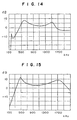
- FIG. 14 is a characteristic diagram of frequency vs sensitivity in comparison with a pole antenna for a middle wave broadcast band. With respect to frequency-sensitivity characteristics in an FM broadcast band, the substantially same result as Example 1 was obtained.
- First coil 31 200 ⁇ H Second coil 32 390 ⁇ H Self-resonance frequency of second coil 32 1.1 MHz High frequency choking coil 52 2.2 ⁇ H Self-resonance frequency of high frequency choking coil 52 90 MHz Resistor 47 150 ⁇ Resistor 49 2.7 k ⁇ Capacitor 50 22 pF Capacitor 51 1,000 pF Choke coil 9 0.4 mH Self-resonance frequency of choke coil 9 1.1 MHz Stray capacitance of defogger 90 200 pF Stray capacitance of antenna conductor 3 30 pF Close capacitance of antenna conductor 3 and defogger 90 20 pF Stray capacitance of cable 7a 45 pF
- a glass sheet for a rear window for an automobile was used and a glass antenna device as shown in Figure 9 was prepared.
- the damping resistors 20, 21 were not provided, and the locations corresponding to the resistors 20, 21 were opened. Further, the resistor 48 was not provided, and the location of the resistor 48 was short-circuited.
- the circuit constants of the elements were as shown in Table 7.
- Figure 15 is a characteristic diagram of frequency vs sensitivity in comparison with a pole antenna for a middle wave broadcast band. With respect to frequency-sensitivity characteristics in an FM broadcast band, the substantially same result as Example 1 was obtained.
- First coil 31 120 ⁇ H Second coil 32 560 ⁇ H Self-resonance frequency of second coil 32 8 MHz High frequency choking coil 52 2.2 ⁇ H Self-resonance frequency of high frequency choking coil 52 90 MHz Resistor 47 220 ⁇ Resistor 49 10 k ⁇ Capacitor 50 22 pF Capacitor 51 220 pF Choke coil 9 1.6 mH Self-resonance frequency of choke coil 9 0.72 MHz
- Stray capacitance of defogger 90 100 pF Stray capacitance of antenna conductor 3 30 pF Close capacitance of antenna conductor 3 and defogger 90 20 pF Stray capacitance of cable 7a 120 pF
- the first resonance is generated by a resonance element which comprises the impedance of the defogger and the inductance of the first coil
- the second resonance is generated by a resonance element which comprises the impedance of the defogger and the inductance of the second coil. Accordingly, the sensitivity in a low frequency band is excellent because resonance at two portions are utilized.
- the filter circuit is electrically connected between the antenna conductor and the defogger to block or attenuate received signals in a high frequency band. Accordingly, a possibility that received signals in the high frequency band excited in the antenna conductor leak to the automobile body as the earth or the like, can be reduced, and the reduction of sensitivity in the high frequency band can be prevented.
- the resonance frequency for the second resonance can be changed by changing only the inductance of the second inductance element while the inductance of the choke coil 9 is not changed. Accordingly, the adjustment of the sensitivity in the low frequency band can easily be made.
Applications Claiming Priority (4)
| Application Number | Priority Date | Filing Date | Title |
|---|---|---|---|
| JP25011298 | 1998-09-03 | ||
| JP25011298 | 1998-09-03 | ||
| JP8450599 | 1999-03-26 | ||
| JP8450599 | 1999-03-26 |
Publications (2)
| Publication Number | Publication Date |
|---|---|
| EP0984506A1 EP0984506A1 (en) | 2000-03-08 |
| EP0984506B1 true EP0984506B1 (en) | 2002-12-11 |
Family
ID=26425535
Family Applications (1)
| Application Number | Title | Priority Date | Filing Date |
|---|---|---|---|
| EP99116827A Expired - Lifetime EP0984506B1 (en) | 1998-09-03 | 1999-09-02 | Glass antenna device for an automobile |
Country Status (6)
| Country | Link |
|---|---|
| US (1) | US6201505B1 (ko) |
| EP (1) | EP0984506B1 (ko) |
| KR (1) | KR20000022838A (ko) |
| DE (1) | DE69904411T2 (ko) |
| HK (1) | HK1025846A1 (ko) |
| TW (1) | TW431022B (ko) |
Families Citing this family (11)
| Publication number | Priority date | Publication date | Assignee | Title |
|---|---|---|---|---|
| DE10114769B4 (de) * | 2001-03-26 | 2015-07-09 | Heinz Lindenmeier | Aktive Breitbandempfangsantenne |
| DE10245813A1 (de) * | 2002-10-01 | 2004-04-15 | Lindenmeier, Heinz, Prof. Dr.-Ing. | Aktive Breitbandempfangsantenne mit Empfangspegelregelung |
| JP4292914B2 (ja) * | 2003-08-07 | 2009-07-08 | パナソニック株式会社 | 携帯受信装置とこれに用いる分波器 |
| DE10350780A1 (de) * | 2003-10-30 | 2005-06-02 | Robert Bosch Gmbh | Fahrzeugscheibenantenne |
| KR20060021766A (ko) * | 2004-09-04 | 2006-03-08 | 현대자동차주식회사 | 자동차용 글래스 안테나 시스템의 접지구조 |
| JP2007300159A (ja) * | 2006-04-27 | 2007-11-15 | Sharp Corp | 回路ユニット、電源バイアス回路、lnb、およびトランスミッタ |
| CN101682108B (zh) * | 2007-06-22 | 2013-01-23 | 旭硝子株式会社 | 汽车用高频玻璃天线 |
| US20120038527A1 (en) * | 2009-04-28 | 2012-02-16 | Kosuke Tanaka | Glass antenna |
| CN103238253B (zh) * | 2010-11-29 | 2014-12-31 | 旭硝子株式会社 | 车辆用玻璃天线及车辆用窗户玻璃 |
| JP6812825B2 (ja) * | 2017-02-14 | 2021-01-13 | Agc株式会社 | ガラスアンテナ及び車両用窓ガラス |
| CN113169429B (zh) * | 2018-12-25 | 2022-04-12 | 住友电气工业株式会社 | 车载传输系统 |
Family Cites Families (16)
| Publication number | Priority date | Publication date | Assignee | Title |
|---|---|---|---|---|
| JPS6269704A (ja) * | 1985-09-21 | 1987-03-31 | Nippon Sheet Glass Co Ltd | アンテナ |
| US5198825A (en) | 1988-06-10 | 1993-03-30 | Nippon Sheet Glass Co., Ltd. | Reception system for a motor vehicle |
| EP0629018A3 (en) * | 1988-07-14 | 1995-06-14 | Asahi Glass Co Ltd | Motor vehicle antenna. |
| US5239302A (en) | 1988-11-22 | 1993-08-24 | Nippon Sheet Glass Company, Ltd. | Wave reception apparatus for a motor vehicle |
| JPH0831730B2 (ja) | 1989-05-26 | 1996-03-27 | 旭硝子株式会社 | 自動車用ガラスアンテナ装置 |
| JPH04249405A (ja) * | 1991-02-05 | 1992-09-04 | Harada Ind Co Ltd | 自動車用ガラスアンテナ |
| JPH04287405A (ja) | 1991-03-15 | 1992-10-13 | Asahi Glass Co Ltd | 自動車用ガラスアンテナ装置 |
| DE69221355T2 (de) * | 1991-03-26 | 1998-01-22 | Nippon Sheet Glass Co Ltd | Scheibenantennensystem für Kraftfahrzeug |
| JPH06177626A (ja) | 1992-12-08 | 1994-06-24 | Nippon Sheet Glass Co Ltd | 窓ガラスアンテナ装置 |
| DE4312259C2 (de) | 1993-04-15 | 1997-04-30 | Flachglas Ag | Kraftfahrzeugantennenscheibe mit AM-Antenne |
| DE69427506T2 (de) | 1993-08-20 | 2001-10-04 | Asahi Glass Co Ltd | Scheibenantenne für ein Automobil |
| JPH1079615A (ja) * | 1995-08-23 | 1998-03-24 | Asahi Glass Co Ltd | 車両用ガラスアンテナ装置 |
| US5905468A (en) * | 1995-08-23 | 1999-05-18 | Asahi Glass Company Ltd. | Glass antenna device for vehicles |
| JP3185915B2 (ja) * | 1996-05-16 | 2001-07-11 | 日本板硝子株式会社 | 窓ガラスアンテナ装置 |
| JPH10126133A (ja) | 1996-10-22 | 1998-05-15 | Asahi Glass Co Ltd | 車両用アンテナ装置 |
| TW423180B (en) * | 1997-01-31 | 2001-02-21 | Terajima Fumitaka | Glass antenna device for an automobile |
-
1999
- 1999-09-01 KR KR1019990036854A patent/KR20000022838A/ko not_active Application Discontinuation
- 1999-09-01 TW TW088115059A patent/TW431022B/zh not_active IP Right Cessation
- 1999-09-02 EP EP99116827A patent/EP0984506B1/en not_active Expired - Lifetime
- 1999-09-02 DE DE69904411T patent/DE69904411T2/de not_active Expired - Fee Related
- 1999-09-03 US US09/390,294 patent/US6201505B1/en not_active Expired - Fee Related
-
2000
- 2000-08-09 HK HK00104973A patent/HK1025846A1/xx not_active IP Right Cessation
Also Published As
| Publication number | Publication date |
|---|---|
| EP0984506A1 (en) | 2000-03-08 |
| DE69904411T2 (de) | 2003-08-14 |
| US6201505B1 (en) | 2001-03-13 |
| HK1025846A1 (en) | 2000-11-24 |
| DE69904411D1 (de) | 2003-01-23 |
| KR20000022838A (ko) | 2000-04-25 |
| TW431022B (en) | 2001-04-21 |
Similar Documents
| Publication | Publication Date | Title |
|---|---|---|
| EP0856904B1 (en) | Glass antenna device for an automobile | |
| US5289197A (en) | Pane antenna having an amplifier | |
| EP0639868B1 (en) | Glass antenna device for an automobile | |
| EP0984506B1 (en) | Glass antenna device for an automobile | |
| EP1177596B1 (en) | Glass antenna device for vehicle and radio receiver apparatus using the same | |
| EP0942486A2 (en) | Glass antenna device for vehicle | |
| JPH1079615A (ja) | 車両用ガラスアンテナ装置 | |
| EP0986129B1 (en) | Glass antenna device for an automobile | |
| AU763286B2 (en) | Glass antenna device for an automobile | |
| JPH11205023A (ja) | 車両用ガラスアンテナ装置 | |
| JP3630031B2 (ja) | 自動車用ガラスアンテナ装置 | |
| JP3508217B2 (ja) | 自動車用ガラスアンテナ装置 | |
| JP3791237B2 (ja) | 自動車用ガラスアンテナ装置 | |
| JP3744214B2 (ja) | 自動車用ガラスアンテナ装置 | |
| JP2001156521A (ja) | 自動車用ガラスアンテナ装置 | |
| JP2001057504A (ja) | 自動車用ガラスアンテナ装置 | |
| JPH098527A (ja) | 自動車用ガラスアンテナ装置 | |
| JPH02256303A (ja) | 自動車用ガラスアンテナ装置 | |
| JP2000174530A (ja) | 車両用ガラスアンテナ装置 | |
| JPH11191712A (ja) | 自動車用ガラスアンテナ装置 | |
| JPH10126133A (ja) | 車両用アンテナ装置 | |
| JP2000188507A (ja) | 車両用ガラスアンテナ装置 | |
| JPH098528A (ja) | 自動車用ガラスアンテナ装置 | |
| JPH1155020A (ja) | 自動車受信用ガラスアンテナ | |
| JPH09284027A (ja) | 自動車用高周波ガラスアンテナ装置 |
Legal Events
| Date | Code | Title | Description |
|---|---|---|---|
| PUAI | Public reference made under article 153(3) epc to a published international application that has entered the european phase |
Free format text: ORIGINAL CODE: 0009012 |
|
| AK | Designated contracting states |
Kind code of ref document: A1 Designated state(s): BE DE FR GB IT |
|
| AX | Request for extension of the european patent |
Free format text: AL;LT;LV;MK;RO;SI |
|
| RAP1 | Party data changed (applicant data changed or rights of an application transferred) |
Owner name: ASAHI GLASS COMPANY LTD. |
|
| 17P | Request for examination filed |
Effective date: 20000323 |
|
| AKX | Designation fees paid |
Free format text: BE DE FR GB IT |
|
| 17Q | First examination report despatched |
Effective date: 20010605 |
|
| GRAG | Despatch of communication of intention to grant |
Free format text: ORIGINAL CODE: EPIDOS AGRA |
|
| GRAG | Despatch of communication of intention to grant |
Free format text: ORIGINAL CODE: EPIDOS AGRA |
|
| GRAH | Despatch of communication of intention to grant a patent |
Free format text: ORIGINAL CODE: EPIDOS IGRA |
|
| GRAH | Despatch of communication of intention to grant a patent |
Free format text: ORIGINAL CODE: EPIDOS IGRA |
|
| GRAA | (expected) grant |
Free format text: ORIGINAL CODE: 0009210 |
|
| AK | Designated contracting states |
Kind code of ref document: B1 Designated state(s): BE DE FR GB IT |
|
| REG | Reference to a national code |
Ref country code: GB Ref legal event code: FG4D |
|
| REF | Corresponds to: |
Ref document number: 69904411 Country of ref document: DE Date of ref document: 20030123 |
|
| ET | Fr: translation filed | ||
| PLBE | No opposition filed within time limit |
Free format text: ORIGINAL CODE: 0009261 |
|
| STAA | Information on the status of an ep patent application or granted ep patent |
Free format text: STATUS: NO OPPOSITION FILED WITHIN TIME LIMIT |
|
| 26N | No opposition filed |
Effective date: 20030912 |
|
| PGFP | Annual fee paid to national office [announced via postgrant information from national office to epo] |
Ref country code: FR Payment date: 20050823 Year of fee payment: 7 |
|
| PGFP | Annual fee paid to national office [announced via postgrant information from national office to epo] |
Ref country code: DE Payment date: 20050825 Year of fee payment: 7 |
|
| PGFP | Annual fee paid to national office [announced via postgrant information from national office to epo] |
Ref country code: GB Payment date: 20050831 Year of fee payment: 7 |
|
| PGFP | Annual fee paid to national office [announced via postgrant information from national office to epo] |
Ref country code: BE Payment date: 20051125 Year of fee payment: 7 |
|
| PG25 | Lapsed in a contracting state [announced via postgrant information from national office to epo] |
Ref country code: BE Free format text: LAPSE BECAUSE OF NON-PAYMENT OF DUE FEES Effective date: 20060930 |
|
| PGFP | Annual fee paid to national office [announced via postgrant information from national office to epo] |
Ref country code: IT Payment date: 20060930 Year of fee payment: 8 |
|
| PG25 | Lapsed in a contracting state [announced via postgrant information from national office to epo] |
Ref country code: DE Free format text: LAPSE BECAUSE OF NON-PAYMENT OF DUE FEES Effective date: 20070403 |
|
| GBPC | Gb: european patent ceased through non-payment of renewal fee |
Effective date: 20060902 |
|
| REG | Reference to a national code |
Ref country code: FR Ref legal event code: ST Effective date: 20070531 |
|
| PG25 | Lapsed in a contracting state [announced via postgrant information from national office to epo] |
Ref country code: GB Free format text: LAPSE BECAUSE OF NON-PAYMENT OF DUE FEES Effective date: 20060902 |
|
| BERE | Be: lapsed |
Owner name: *ASAHI GLASS CY LTD Effective date: 20060930 |
|
| PG25 | Lapsed in a contracting state [announced via postgrant information from national office to epo] |
Ref country code: FR Free format text: LAPSE BECAUSE OF NON-PAYMENT OF DUE FEES Effective date: 20061002 |
|
| PG25 | Lapsed in a contracting state [announced via postgrant information from national office to epo] |
Ref country code: IT Free format text: LAPSE BECAUSE OF NON-PAYMENT OF DUE FEES Effective date: 20070902 |