EP0982801A2 - Matériau en nid d' abeilles absorbant les ondes radio et absorbant d' ondes radio avec ce matériau - Google Patents
Matériau en nid d' abeilles absorbant les ondes radio et absorbant d' ondes radio avec ce matériau Download PDFInfo
- Publication number
- EP0982801A2 EP0982801A2 EP99116758A EP99116758A EP0982801A2 EP 0982801 A2 EP0982801 A2 EP 0982801A2 EP 99116758 A EP99116758 A EP 99116758A EP 99116758 A EP99116758 A EP 99116758A EP 0982801 A2 EP0982801 A2 EP 0982801A2
- Authority
- EP
- European Patent Office
- Prior art keywords
- incombustible
- honeycomb
- radio
- absorptive material
- honeycomb structure
- Prior art date
- Legal status (The legal status is an assumption and is not a legal conclusion. Google has not performed a legal analysis and makes no representation as to the accuracy of the status listed.)
- Granted
Links
Images


Classifications
-
- H—ELECTRICITY
- H05—ELECTRIC TECHNIQUES NOT OTHERWISE PROVIDED FOR
- H05K—PRINTED CIRCUITS; CASINGS OR CONSTRUCTIONAL DETAILS OF ELECTRIC APPARATUS; MANUFACTURE OF ASSEMBLAGES OF ELECTRICAL COMPONENTS
- H05K9/00—Screening of apparatus or components against electric or magnetic fields
-
- H—ELECTRICITY
- H05—ELECTRIC TECHNIQUES NOT OTHERWISE PROVIDED FOR
- H05K—PRINTED CIRCUITS; CASINGS OR CONSTRUCTIONAL DETAILS OF ELECTRIC APPARATUS; MANUFACTURE OF ASSEMBLAGES OF ELECTRICAL COMPONENTS
- H05K9/00—Screening of apparatus or components against electric or magnetic fields
- H05K9/0001—Rooms or chambers
- H05K9/0003—Shielded walls, floors, ceilings, e.g. wallpaper, wall panel, electro-conductive plaster, concrete, cement, mortar
-
- H—ELECTRICITY
- H01—ELECTRIC ELEMENTS
- H01Q—ANTENNAS, i.e. RADIO AERIALS
- H01Q17/00—Devices for absorbing waves radiated from an antenna; Combinations of such devices with active antenna elements or systems
-
- H—ELECTRICITY
- H01—ELECTRIC ELEMENTS
- H01Q—ANTENNAS, i.e. RADIO AERIALS
- H01Q17/00—Devices for absorbing waves radiated from an antenna; Combinations of such devices with active antenna elements or systems
- H01Q17/008—Devices for absorbing waves radiated from an antenna; Combinations of such devices with active antenna elements or systems with a particular shape
-
- Y—GENERAL TAGGING OF NEW TECHNOLOGICAL DEVELOPMENTS; GENERAL TAGGING OF CROSS-SECTIONAL TECHNOLOGIES SPANNING OVER SEVERAL SECTIONS OF THE IPC; TECHNICAL SUBJECTS COVERED BY FORMER USPC CROSS-REFERENCE ART COLLECTIONS [XRACs] AND DIGESTS
- Y10—TECHNICAL SUBJECTS COVERED BY FORMER USPC
- Y10T—TECHNICAL SUBJECTS COVERED BY FORMER US CLASSIFICATION
- Y10T428/00—Stock material or miscellaneous articles
- Y10T428/24—Structurally defined web or sheet [e.g., overall dimension, etc.]
- Y10T428/24149—Honeycomb-like
Definitions
- the present invention relates to an incombustible honeycomb radio absorptive material and to a radio absorber using it. More specifically, the invention relates to an incombustible honeycomb radio absorptive material which is suitably used for an anechoic chamber (radio shielding room), has a high incombustibility, is excellent in radio absorptivity, is lightweight, and has a high strength, as well as to a radio absorber using the material.
- the measurement of said electromagnetic wave noises is usually carried out in an anechoic chamber where no reflection is caused of electromagnetic waves, and the inside wall of the anechoic chamber is made with a radio absorber.
- a radio absorber it is mostly used an organic material, such as foamed polystyrene and foamed polyurethane, where each being compounded with carbon black for improving electric conductivity, however, incombustibility is low of foamed polystyrene or foamed polyurethane.
- an organic material such as foamed polystyrene and foamed polyurethane, where each being compounded with carbon black for improving electric conductivity, however, incombustibility is low of foamed polystyrene or foamed polyurethane.
- the test of a large electric power such as an immunity test, would be a mandatory one in Japan.
- a radio absorber to be used for said chamber is required to have, in addition to radio absorptivity, a higher incombus
- Radio absorbers having incombustibility have been proposed as follows: a heat-resisting incombustible radio absorber made of a shaped material formed by cumulating and bonding many closed cellular inorganic particles with a heat-resisting inorganic adhesive having a definite amount of carbon black dispersed therein (Japanese Patent No. 2,743,227); a radio absorber obtained by attaching and fixing an electrically conductive material to a molded material comprising ceramic or glass short fibers each having a specific aspect ratio by penetration and impregnation (Japanese Patent Laid-Open No.
- radio absorber made of a composition constituted by a cement, a light-weight aggregate, non-electrically conductive fibers, and a synthetic resin emulsion (Japanese Patent Laid-Open No. 67,544/1996).
- the heat-resisting incombustible radio absorber of Japanese Patent No. 2,743,227 is structurally weak, having low mechanical strength, and as it is formed with many closed cellular particles, dusts are apt to be generated during assembling the absorber and by a mutual-contact of the particles.
- the above conventional radio absorbers each is heavy in its own weight, and therefore, each of them is easily distorted by its own weight to cause deformation or breakage.
- radio absorbers be made in honeycomb structures (Japanese Patent Laid-Open Nos. 205,000/1991 and 132,691/1994, etc.).
- those radio absorbers are quite inferior in fire resistance, as the supporting materials therefor are papers or plastics.
- An object of the invention is to provide an incombustible honeycomb radio absorptive material which is excellent in fire resistance and radio absorptivity, is lightweight, and has a high strength.
- Another object of the invention is to provide a radio absorber using the radio absorptive material above.
- one aspect of this invention is directed to an incombustible honeycomb radio absorptive material forming a honeycomb structure that is an aggregate of many cells, where the honeycomb structure contains a hydrated inorganic compound and an electrically conductive material.
- another aspect of this invention is directed to an incombustible honeycomb radio absorptive material forming a honeycomb structure that is an aggregate of many cells, wherein the honeycomb structure contains a hydrated inorganic compound, and has an electrically conductive layer made of an electrically conductive material formed on the surface of the structure.
- a still another aspect of this invention is directed to a radio absorber wherein a large number of the incombustible honeycomb radio absorptive materials are disposed on a shield panel or on a ferrite tile covering the shield panel.
- the incombustible honeycomb radio absorptive material of the invention forms a honeycomb structure which is made of an aggregate of many cells, wherein said honeycomb structure contains a hydrated inorganic compound as a main constituent and contains an electrically conductive material (in the first embodiment); or forms a honeycomb structure which is made of an aggregate of many cells, wherein said honeycomb structure contains a hydrated inorganic compound as a main constituent, and has an electrically conductive layer made of an electrically conductive material formed on the surface of the structure (in the second embodiment).
- the honeycomb structure itself is imparted with incombustibility as well as radio absorptivity, and is used as the incombustible honeycomb radio absorptive material.
- the honeycomb structure is imparted with incombustibility, and further an electrically conductive layer is formed on the surface of the structure to impart radio absorptivity therefor, and the resulting assembly of the honeycomb structure and the electrically conductive layer is used as the incombustible honeycomb radio absorptive material.
- incombustibility means bearing the building material test (Notification No. 1828 of the Ministry of Assembly, Japan), that is, when a sample is placed in a furnace of 750°C for 20 minutes, if a temperature rise in the furnace, i. e., a temperature rise of the sample, is lower than 50°C, then the sample is judged to be incombustible.
- radiation absorptivity means the characteristics of the material whose reflectivity is -20 dB or lower.
- the honeycomb structure of the present invention may be produced by any arbitrary methods, such as a method of integral molding and a method of sticking sheets to each other, however, it is preferably obtained by producing wet sheets from a slurry containing a hydrated inorganic compound as a main constituent (in the first embodiment, further containing the electrically conductive material), and then drying and solidifying the wet sheets to form sheets, followed by laminating the sheets in a honeycomb form.
- a honeycomb structure 1 is formed by laminating plural sheets 2 by an inorganic adhesive 3, followed by extending.
- Each sheet 2 contains a hydrated inorganic compound as a main constituent.
- Any arbitrary adhesives may be used as the inorganic adhesive 3, such as a water glass-based adhesive, a phosphate-based adhesive, a colloidal silica-based adhesive, and a colloidal alumina-based adhesive, and the like.
- An organic adhesive such as vinyl acetate, etc., may be used in place of the inorganic adhesive, however, in terms of the fire resistance and the heat resistance, the use of the inorganic adhesive is more preferred.
- an electrically conductive layer 4 is formed on the surface of the sheet 2.
- the hydrated inorganic compound mainly contained in the sheet 2 include sepiolite; a hydrate of aluminum hydroxide, magnesium hydroxide, or calcium hydroxide; gypsum dihydrate; calcium aluminate hydrate; and wollastonite.
- sepiolite is mostly preferred.
- the invention is described by exemplifying sepiolite for the hydrated inorganic compound.
- Sepiolite is a clay mineral usually called mountain leather, mountain cork, or mountain wood, and meerschaum in Japan is a kind of sepiolite.
- the external appearance of sepiolite may be in a cork form or a leather form, or in a pure-white soft lump, and is generally a lump of magnesium silicate having fibrous properties.
- Sepiolite has hydroxyl groups having high reactivity on the surface thereof, and has fundamental properties, such as an adsorptivity, a thixotropy, and a consolidating property.
- any material having electric conductivity may be used without particular restrictions, however, in terms of excellency in radio absorptivity, carbon black, carbon graphite, carbon fibers, etc., are preferably used.
- the electrically conductive materials may be used singly or as a mixture of two or more thereof.
- the sheet 2 is preferably obtained by sheet-manufacturing using a slurry containing sepiolite as a main constituent (in the first embodiment, further contains an electrically conductive material), followed by dehydrating the slurry to form a wet sheet, then drying and solidifying to obtain a sheet.
- the thickness of the sheet 2 is preferably about 0.2 - 0.7 mm.
- the slurry is prepared by dispersing sepiolite (in the first embodiment, sepiolite and an electrically conductive material) in a binder such as water glass, and further inorganic fibers may be added to as a reinforcing material.
- the inorganic fibers include glass fibers, rock wool fibbers, stainless steel fibers, silica-alumina fibers, and potassium titanate fibers.
- the content of the inorganic fibers is preferably not more than 20 wt% in the total weight of the sheet.
- organic fibers such as a wood pulp or aramid fibers, may be further incorporated thereinto. However, in terms of inflammability and sufficient shape-retention keeping, the content of the organic fibers is preferably not more than 5 wt% in the total weight of the sheet.
- thermosetting synthetic resin such as polyamidoamine and epichlorohydrin
- thermoplastic resin an anionic thermoplastic resin, such as polyacrylamide (molecule weight of about 800,000 - 1,000,000), etc., is preferably used.
- sepiolite is excellent in the consolidating property, in the case of using said synthetic resin as a binder, the content thereof is preferably not more than 5 wt%, and such the content substantially does not influence the incombustibility of the sheet.
- the content of sepiolite in the sheet 2 is preferably not more than 90 wt%, and particularly preferred not more than 85 wt%; and is preferably not less than 50 wt%, more preferably not less than 65 wt%, and particularly preferred not less than 75 wt%.
- the said content corresponds to the content of sepiolite in the total weight of the honeycomb structure.
- the content of the electrically conductive material is preferably not more than 30 g/l, and particularly preferred not more than 20 g/l in the total volume (the volume including the cell spaces) of the honeycomb structure; and is preferably not less than 0.5 g/l, and particularly preferred not less than 2 g/l in the total volume (the volume including the cell spaces) of the honeycomb structure.
- a slurry is exemplified comprising 85 wt% of sepiolite, 10 wt% of glass fibers, 3 wt% of a pulp, 1 wt% of vinylon-based fibers, 0.5 wt% of an acrylic resin, and 0.5 wt% of an epoxy resin.
- the total weight is 5 wt% of the organic components such as the pulp.
- the organic components are carbonized under heating temperature conditions of 800 - 1,000°C, but in the sheet after the carbonization, the strength of the sheet is scarcely deteriorated, and the sheet has a sufficient heat-resisting shape-retention. When the sheet 2 is immersed in water, it is not re-dissolved and the strength thereof is not lowered.
- the thickness of the sheet 2 is preferably about 0.2 - 0.7 mm, and particularly preferred about 0.2 - 0.25 mm.
- a slurry is exemplified comprising 78 wt% of sepiolite, 10 wt% of an electrically conductive material, 5 wt% of glass fibers, 3 wt% of a pulp, 2 wt% of vinylon-based fibers, 1 wt% of an acrylic resin, and 1 wt% of an epoxy resin.
- the concentration of the slurry is preferably about 0.05 - 0.5 wt%.
- the wet sheet is obtained by dehydrating the product in the sheet-manufacturing process from the slurry.
- the sheet is formed from two or more plural layers, and a glass cloth may be sandwiched between the sheet layers.
- Such a sheet of laminated layer structure is obtainable by manufacturing wet sheets from the slurry, then laminating two or more layers of the wet sheets, followed by fixing a glass cloth between each of the layers, and drying them.
- the fixing of the glass cloth between the layers may be sandwiched between the layers using an inorganic adhesive, or by press-sticking.
- the glass cloth is commercially available as, for example, "Microglass Roving Cloth” and Microglass Uniroving" (both are of Nippon Sheet Glass Co., Ltd.), and those are preferably used.
- the thickness of the glass cloth is preferably about 0.3 - 0.8 mm, and the total thickness of the sheets is preferably about 0.8 - 1.3 mm.
- the honeycomb structure 1 can be formed by any known means using the sheet 2.
- an inorganic adhesive 3 is coated onto the surface of the sheet 2 in stripe forms with a definite width at a constant interval by screen transfer, roller coating, etc.
- the width of the stripe of the inorganic adhesive 3 determines the length of the cumulated portion of the main body 1 of the honeycomb structure, and by changing the width and pitch of the stripes of the adhesive 3, the form and dimensions of the cells constituting the honeycomb structure main body 1 may be desirably changed.
- Many sheets 2 each having formed the stripes of the inorganic adhesive 3 are cumulated such that the stripes of the adhesive 3 are shifted from those between the adjacent sheets 2 by a half pitch and they are adhered to each other by pressing them in the vertical direction.
- the block composed of many sheets 2 adhered to each other is cut in the direction perpendicular to the stripes of the adhesive 3 with a definite width according to the thickness of the desired honeycomb structure. After that, by extending the cut sheets from both sides, a honeycomb main body 1 is formed.
- an electrically conductive layer 4 made of an electrically conductive material is formed on the surface of the honeycomb structure 1.
- the electrically conductive material may be used as the same one as that of described in the first embodiment.
- the formation of the electrically conductive layer 4 can be carried out by any ordinary methods.
- the method of coating the electrically conductive coating liquid on the surface of the honeycomb structure using a brush, and the method of immersing the honeycomb structure in the coating liquid to form an electrically conductive layer onto the surface thereof are preferred.
- a water glass-based binder, a silica-alumina-based binder, etc. are exemplified, but not limited to them.
- the content of the electrically conductive material in the electrically conductive layer is preferably not more than 30 g/l, and particularly preferred not more than 20 g/l in the total volume (the volume including the cell spaces) of the honeycomb structure; and is preferably not less than 0.5 g/l, and particularly preferred not less than 2 g/l in the total volume (the volume including the cell spaces) of the honeycomb structure.
- An inorganic coat made of water glass, etc. may be formed onto the surface of the incombustible honeycomb radio absorptive material formed as described above.
- the tensile strength and compressive strength of the incombustible honeycomb radio absorptive material are more increased by the inorganic coat, and the incombustible honeycomb absorptive material is maintained in the extended state of the honeycomb structure. Also, the occurrence of scuffing or peeling off of the fibers on the surface of the sheet 2 is prevented, and further, the fire resistance of the sheet 2 can be more improved.
- the cell size of the honeycomb structure and the thickness of the honeycomb structure give influences on the characteristics of the radio absorber.
- the opening of the cell size of the honeycomb structure is too large, an electromagnetic wave is liable to transmit through the absorptive material, and in the case of using said radio absorptive material for an anechoic chamber, the transmitted electromagnetic wave is reflected to the inside of the anechoic chamber by a shield panel disposed on the back surface thereof, and the reflectivity is heightened.
- the thickness of the honeycomb structure is too thin, an electromagnetic wave is not sufficiently absorbed, and the reflectivity is heightened.
- the opening of the cell size of the honeycomb structure becomes smaller or when the thickness of the honeycomb structure becomes thicker, then it leads to the increase of the weight of the radio absorber.
- the upper limit of the cell size of the honeycomb structure is preferably 60 mm, more preferably 50 mm, and particularly preferred 30 mm; and the lower limit of the cell size is preferably 5 mm, and particularly preferred 10 mm.
- the upper limit of the thickness of the honeycomb structure is preferably 50 mm, and particularly preferred 30 mm; and the lower limit of the thickness of the honeycomb structure is preferably 10 mm, and particularly preferred 15 mm.
- the cell size of the honeycomb structure means the size shown by "d” in Fig. 2, and the thickness of the honeycomb structure means the thickness shown by "c” in Fig. 2.
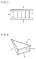
- an incombustible sheet material 5 may be stuck to at least one surface of the honeycomb structure 1 as shown in Fig. 3.
- Fig. 3 shows the embodiment of sticking the materials onto the both surfaces of the honeycomb structure 1.
- the incombustible sheet material 5 may be stuck to by using an inorganic adhesive 3.
- the incombustible sheet material 5 containing a hydrated inorganic compound, preferably sepiolite, as a main constituent is preferably used as in the case of the sheet 2, and is obtainable in the same way as the sheet 2.
- the thickness of the incombustible sheet material 5 is preferably about 0.5 - 3.0 mm.
- the incombustible sheet materials 5, 5 having a different thickness from each other may be stuck to the both surfaces of the honeycomb structure 1, respectively.
- the surface (the opposite side to the sticking-side to the honeycomb structure 1) of the incombustible sheet material 5 may be applied with an embossing work, whereby being able to apply a beautiful decoration of the surface of a radio absorber.
- the incombustible honeycomb radio absorptive materials in the first and second embodiments of the invention may be applied to radio absorbers in various manners.
- the latter method is preferred in view of the capability of radio absorptivity of an electromagnetic wave of a low frequency.
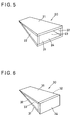
- Figs. 4 - 6 are schematic slant views showing specific examples of preferred assembly forms (assemblies for radio absorbers) of radio absorptive materials for forming radio absorbers of this invention.
- a radio absorber assembly 10 shown in Fig. 4 has a square pyramid form.
- the radio absorber assembly 10 has four sheets of side wall portions 12 of an isosceles triangle form, the inside thereof is a hollow structure 13 for weight reduction, and an opening 14 is formed at the bottom portion.
- the radio absorber assembly 20 shown in Fig. 5 has a wedge form.
- the radio absorber assembly 20 has inclined portions 21, 21 and side wall portions 22, 22 each disposed between the inclined portions, the inside is a hollow structure 23 for weight reduction, and an opening 24 is formed at the bottom portion.
- the radio absorber assembly 30 shown in Fig. 6 has a wedge form.
- the radio absorber assembly 30 has inclined portions 31, 31 and a bottom portion 34, side wall portions disposed between the inclined portions form openings 32, 32, and the inside thereof is a hollow structure for weight reduction.
- Each assembly is formed by using an inorganic adhesive or an organic one.
- an inorganic adhesive the same one as described hereinbefore is preferably used, and for the organic adhesive, an epoxy-based one is preferably used.
- the radio absorber 50 of the invention can be obtained.
- a radio absorptive ferrite tile 52 may be formed on the shield panel 51, and by disposing the radio absorber assembly on the ferrite tile 52 in the above-described manner, the radio absorber 50 of the invention may be obtained.
- the incombustible honeycomb radio absorptive materials of this invention can be handled as sheet-form incombustible honeycomb radio absorptive materials at transporting the materials before assembling them as many three-dimensional radio absorber structures.
- a flat radio transmitter may be placed on the front surface of the radio absorber. It is preferred that the radio transmitter is lightweight and has the property of transmitting a radio wave without reflecting it and without reducing the characteristics of the radio absorber.
- the shied panel is placed in a perpendicular direction as a wall surface such that the tips of the assembly disposed on the panel turn the horizontal direction.
- the construction of the chamber can be carried out by an ordinary method.
- the incombustible honeycomb radio absorptive material of this invention and the radio absorber of this invention using said material are particularly excellent in the attenuation effect of the electromagnetic waves of the frequency of from about 30 MHz to 18 GHz.
- the radio absorber is obtained, which is excellent in incombustibility and radio absorptivity, is lightweight, and is not deformed by its own weight.
- Carbon graphite (“Blue P” of Nippon Kokuen K.K.) was dispersed in an inorganic binder ("FJ 803" of Tokiwa Electric Co.) such that the content thereof was 20 wt%, to obtain an electronically conductive coating liquid.
- the electronically conductive liquid was coated onto the surface of a honeycomb structure ("Ceramic Honeycomb" of Tokiwa Electric Co.; cell size 20mm, thickness 20mm, containing 85 wt% sepiolite) such that the content of the carbon graphite was 4 g/l in the total volume (the total volume including the cell spaces) of the honeycomb structure, followed by drying it to form an electrically conductive layer.
- a honeycomb structure (“Ceramic Honeycomb" of Tokiwa Electric Co.; cell size 20mm, thickness 20mm, containing 85 wt% sepiolite) such that the content of the carbon graphite was 4 g/l in the total volume (the total volume including the cell spaces) of the honeycomb structure, followed by drying it to form an electrically conductive layer.
- the honeycomb structure having the electrically conductive layer formed thereon was cut to prepare a board of 650 mm ⁇ 1,400 mm ⁇ 20 mm. Then, from the board, two cut pieces of a trapezoid form having an upper side of 400 mm, a lower side of 600 mm, and a height of 1,050 mm were obtained. Using each cut piece thusly obtained, a wedge-form radio absorber assembly having a bottom area of 600 mm ⁇ 600 mm and a height of 1,000 mm was prepared. The specific gravity of the wedge-form radio absorber assembly was 0.04 g/cm 3 .
- An incombustible sheet material (thickness: 1.5 mm) was stuck to both surfaces of the honeycomb structure having the electrically conductive layer obtained in Example 1, using an inorganic adhesive (a mixture of potassium silicate and antimony pentaoxide).
- the incombustible sheet material was produced as follows. Firstly, a slurry for the incombustible sheet having the following composition was prepared using a Henschel mixer.
- incombustible sheets having a thickness of 0.5 mm were manufactured.
- an incombustible sheet material having a thickness of 1.5 mm was produced.
- the honeycomb structure having the thus-produced incombustible sheet material stuck to both surfaces thereof was cut into a board of 650 mm ⁇ 1,400 mm ⁇ 23 mm. Then, from the board, two cut pieces of a trapezoid form having an upper side of 400 mm, a lower side of 600 mm, and a height of 1,050 mm were obtained. Using each cut piece, a wedge-form radio absorber assembly having a bottom area of 600 mm ⁇ 600 mm and a height of 1,000 mm was prepared. The specific gravity of the wedge-form radio absorber assembly was 0.13 g/cm 3 .
- Carbon fibers (“Dialead” of Mitsubishi Chemical Corporation, fiber length: 10 mm) was dispersed in an inorganic binder ("FJ 803" of Tokiwa Electric Co.) such that the content thereof was 10 wt%, to obtain an electrically conductive coating liquid.
- the electrically conductive coating liquid was coated onto both surfaces of a honeycomb structure ("Ceramic Honeycomb" of Tokiwa Electric Co.; cell size 20 mm, thickness 20 mm, containing 85 wt% sepiolite) such that the content of the carbon fibers was 3 g/l in the total volume (the total volume including the cell spaces) of the honeycomb structure, followed by drying it to form an electrically conductive layer.
- a honeycomb structure of Tokiwa Electric Co.; cell size 20 mm, thickness 20 mm, containing 85 wt% sepiolite
- the honeycomb structure having the electrically conductive layer formed thereon was cut to prepare a board of 650 mm ⁇ 1,400 mm ⁇ 20 mm. Then, from the board, two cut pieces of a trapezoid form having an upper side of 400 mm, a lower side of 600 mm, and a height of 1,050 mm were obtained. Using each cut piece thusly obtained, a wedge-form radio absorber assembly having a bottom area of 600 mm ⁇ 600 mm and a height of 1,000 mm was prepared. The specific gravity of the wedge-form radio absorber assembly was 0.04 g/cm 3 .
- a dehydration treatment was carried out to provide a wet sheet. Then, a two-layered wet sheet was prepared, and after that a glass cloth was sandwiched between the layers, followed by drying and solidifying.
- a honeycomb structure [cell size: 20 mm, thickness: 20 mm, the content of the carbon fibers in the total volume (total volume including the cell spaces) of the honeycomb structure: 3 g/l] was prepared.
- a board of 650 mm ⁇ 1,400 mm ⁇ 20 mm was prepared. Then, from the board, two cut pieces of a trapezoid form having an upper side of 400 mm, a lower side of 600 mm, and a height of 1,050 mm were obtained. Using each cut piece thusly obtained, a wedge-form radio absorber assembly having a bottom area of 600 mm ⁇ 600 mm and a height of 1,000 mm was prepared. The specific gravity of the wedge-form radio absorber assembly was 0.04 g/cm 3 .
- Carbon graphite (“Blue P” of Nippon Kokuen K.K.) was dispersed in an inorganic binder ("FJ 803" of Tokiwa Electric Co.) such that the content thereof was 30 wt%, to obtain an electronically conductive coating liquid.
- the electronically conductive liquid was coated onto the surface of a honeycomb structure ("Ceramic Honeycomb" of Tokiwa Electric Co.; cell size: 30 mm, thickness: 30 mm, containing 85 wt% sepiolite) such that the content of the carbon graphite was 18 g/l in the total volume (the total volume including the cell spaces) of the honeycomb structure, followed by drying it to form an electrically conductive layer.
- a honeycomb structure of Tokiwa Electric Co.; cell size: 30 mm, thickness: 30 mm, containing 85 wt% sepiolite
- the honeycomb structure having the electrically conductive layer formed thereon was cut to prepare a board of 650 mm ⁇ 1,400 mm ⁇ 30 mm. Then, from the board, two cut pieces of a trapezoid form having an upper side of 400 mm, a lower side of 600 mm, and a height of 1,050 mm were obtained. Using each cut piece thusly obtained, a wedge-form radio absorber assembly having a bottom area of 600 mm ⁇ 600 mm and a height of 1,000 mm was prepared. The specific gravity of the wedge-form radio absorber assembly was 0.07 g/cm 3 .
- Carbon graphite (“Blue P” of Nippon Kokuen K.K.) was dispersed in an inorganic binder ("FJ 803" of Tokiwa Electric Co.) such that the content thereof was 10 wt%, to obtain an electronically conductive coating liquid.
- the electronically conductive liquid was permeated in the surface of a honeycomb structure ("Ceramic Honeycomb" of Tokiwa Electric co.; cell size: 10 mm, thickness: 20 mm, containing 85 wt% sepiolite) such that the content of the carbon graphite was 1 g/l to the honeycomb structure, followed by drying it to form an electrically conductive layer.
- a honeycomb structure "Ceramic Honeycomb" of Tokiwa Electric co.; cell size: 10 mm, thickness: 20 mm, containing 85 wt% sepiolite) such that the content of the carbon graphite was 1 g/l to the honeycomb structure, followed by drying it to form an electrically conductive layer.
- the honeycomb structure having the electrically conductive layer formed thereon was cut to prepare a board of 650 mm ⁇ 1,400 mm ⁇ 20 mm. Then, from the board, two cut pieces of a trapezoid form having an upper side of 400 mm, a lower side of 600 mm, and a height of 1,050 mm were obtained. Using each cut piece thusly obtained, a wedge-form radio absorber assembly having a bottom area of 600 mm ⁇ 600 mm and a height of 1,000 mm was prepared. The specific gravity of the wedge-form radio absorber assembly was 0.06 g/cm 3 .
- each of the wedge-form radio absorber assemblies (the type shown by numeral 20 of Fig. 5) obtained in Examples 1 - 6 was formed a ferrite tile 52 ("Ferrite IB-011" of TDK Corporation, thickness: 5.9 mm), and further a shield panel 51 was disposed at the back surface thereof (see Fig. 7).
- each wedge-form radio absorber assembly 20 was irradiated with a radio wave, and the reflected wave level was measured in the anechoic chamber.
- the reflectivity at 1 GHz measured by the above-described method was -26 dB in Example 1; -24 dB in Example 2; -28 dB in Example 3; -21 dB in Example 4; -24 dB in Example 5; and -20 dB in Example 6, respectively.
- the test was carried out according to the test method of an incombustible material regulated by the Notification No. 1828 of the Ministry of Assembly, Japan. That is, firstly, using an inorganic adhesive ("FJ 294" of Tokiwa Electric co.), the honeycomb structural bodies obtained in each of Examples 1 - 6 were laminated to prepare test samples of 40 mm ⁇ 40 mm ⁇ 50 mm. Then, each test sample was heated in a furnace to 750°C ⁇ 10°C for 20 minutes, and the temperature rise of the test sample by the heating was measured. When the temperature rise (over 750°C ⁇ 10°C) of the test sample is lower than 50°C, then the said sample is judged as being incombustible.
- the temperature rise of the test sample was 769°C in Example 1; 759°C in Example 2; 770°C in Example 3; 773°C in Example 4; 784°C in Example 5; and 768°C in Example 6.
- a bending strength was measured according to JIS A1408. That is, from the honeycomb structure obtained in Example 2, a test piece having a length of 200 mm, a width of 150 mm, and a thickness of 18 mm (including 1.5 mm of each thickness of the incombustible sheet material formed at both surfaces thereof) was prepared, and after allowing stand the test piece in an air-drying state, a bending strength was measured at a pressing speed of 1 mm/minute. As the result, the bending strength was 110 kgf/cm 2 .
- an incombustible honeycomb radio absorptive material which has high incombustibility, is excellent in radio absorptivity, is lightweight, and has a high strength, as well as a radio absorber using said material are obtained.
- the present invention is particularly suitably applied to an anechoic chamber.
Landscapes
- Engineering & Computer Science (AREA)
- Microelectronics & Electronic Packaging (AREA)
- Shielding Devices Or Components To Electric Or Magnetic Fields (AREA)
- Building Environments (AREA)
- Laminated Bodies (AREA)
Applications Claiming Priority (2)
| Application Number | Priority Date | Filing Date | Title |
|---|---|---|---|
| JP10242989A JP2000077883A (ja) | 1998-08-28 | 1998-08-28 | 不燃性ハニカム電波吸収材およびこれを用いた電波吸収体 |
| JP24298998 | 1998-08-28 |
Publications (3)
| Publication Number | Publication Date |
|---|---|
| EP0982801A2 true EP0982801A2 (fr) | 2000-03-01 |
| EP0982801A3 EP0982801A3 (fr) | 2000-05-17 |
| EP0982801B1 EP0982801B1 (fr) | 2005-10-26 |
Family
ID=17097250
Family Applications (1)
| Application Number | Title | Priority Date | Filing Date |
|---|---|---|---|
| EP99116758A Expired - Lifetime EP0982801B1 (fr) | 1998-08-28 | 1999-08-30 | Matériau en nid d' abeilles absorbant les ondes radio et absorbant d' ondes radio avec ce matériau |
Country Status (5)
| Country | Link |
|---|---|
| US (1) | US6217978B1 (fr) |
| EP (1) | EP0982801B1 (fr) |
| JP (1) | JP2000077883A (fr) |
| KR (1) | KR100333568B1 (fr) |
| DE (1) | DE69927895T2 (fr) |
Cited By (6)
| Publication number | Priority date | Publication date | Assignee | Title |
|---|---|---|---|---|
| EP1383138A1 (fr) * | 2002-07-18 | 2004-01-21 | Hokkaido University | Absorption des ondes électromagnetique |
| EP1872439A1 (fr) * | 2005-04-21 | 2008-01-02 | Bell Helicopter Textron Inc. | Procede et appareil de diminution de la signature infrarouge et radar d'un vehicule |
| CN103397914A (zh) * | 2013-07-09 | 2013-11-20 | 内蒙古鄂尔多斯联合化工有限公司 | 梳齿迷宫密封式背压式汽轮机蜂窝密封方法 |
| CN109713456A (zh) * | 2017-10-24 | 2019-05-03 | 蔡钧 | 一种毫米波背景吸收装置 |
| WO2020198593A1 (fr) * | 2019-03-27 | 2020-10-01 | Warwick Mills, Inc. | Blindage électromagnétique flexible et pliable |
| US11333465B2 (en) | 2019-05-07 | 2022-05-17 | Warwick Mills, Inc. | Camouflage cover having a visual appearance and visible and IR spectral signatures that closely match a vegetative environment |
Families Citing this family (17)
| Publication number | Priority date | Publication date | Assignee | Title |
|---|---|---|---|---|
| JP4299387B2 (ja) * | 1998-10-05 | 2009-07-22 | Tdk株式会社 | 電波吸収体組立用部材および電波吸収体の製造方法 |
| JP2003110278A (ja) * | 2001-10-01 | 2003-04-11 | Tdk Corp | 電波吸収体、電波吸収シートならびにそれらの製造方法 |
| JP4235735B2 (ja) * | 2002-07-18 | 2009-03-11 | 国立大学法人 北海道大学 | 電磁波吸収体 |
| JP2004154324A (ja) * | 2002-11-06 | 2004-06-03 | Aehf Japan Kk | 化学物質不耐症及び互いに合併しやすい電磁波過敏症の診療治療施設 |
| JP4346360B2 (ja) | 2002-12-25 | 2009-10-21 | 東レ株式会社 | 電波吸収体用シート材および電波吸収体 |
| JP2004335999A (ja) * | 2003-04-17 | 2004-11-25 | Miyagawa Kasei Ind Co Ltd | 電磁波吸収複合体およびその製造方法 |
| WO2005053328A1 (fr) * | 2003-11-28 | 2005-06-09 | Joinset Co., Ltd. | Joint electroconducteur |
| JP4144754B2 (ja) | 2004-05-31 | 2008-09-03 | Tdk株式会社 | 電波吸収体 |
| JP5140348B2 (ja) * | 2007-08-31 | 2013-02-06 | ニッタ株式会社 | 電波吸収体、電波吸収パネル構造体、無線通信改善システム |
| US7940204B1 (en) * | 2009-05-28 | 2011-05-10 | Orbit Advanced Technologies, Inc. | Absorber assembly for an anechoic chamber |
| US11299619B2 (en) * | 2011-07-01 | 2022-04-12 | The Boeing Company | Composite structure having an inorganic coating adhered thereto and method of making same |
| WO2019094683A1 (fr) * | 2017-11-09 | 2019-05-16 | Gramercy Extremity Orthopedics, Llc | Système et procédé d'alimentation en produits chirurgicaux |
| CN110039841A (zh) * | 2018-01-15 | 2019-07-23 | 哈尔滨工业大学 | 一种蝴蝶结状Co/C纳米吸波材料填充的蜂窝夹芯结构吸波复合材料的制备方法 |
| RU2688635C1 (ru) * | 2018-04-06 | 2019-05-22 | Федеральное государственное казенное военное образовательное учреждение высшего образования "Военный учебно-научный центр Военно-воздушных сил "Военно-воздушная академия имени профессора Н.Е. Жуковского и Ю.А. Гагарина" (г. Воронеж) Министерства обороны Российской Федерации | Устройство для защиты от электромагнитного излучения |
| KR102199557B1 (ko) * | 2019-11-27 | 2021-01-07 | 경상대학교산학협력단 | 허니컴 샌드위치 구조의 전자기파 흡수체 및 이를 적용한 스텔스 구조물 |
| FR3115230B1 (fr) * | 2020-10-21 | 2023-04-14 | Univ Rennes | Structure alveolaire fonctionnalisee, structure composite sandwich, procede de fabrication, procede d'optimisation et dispositifs associes |
| WO2022268384A1 (fr) * | 2021-06-24 | 2022-12-29 | Airbus Defence And Space Sas | Plateforme satellitaire présentant des caractéristiques améliorées de découplage électromagnétique entre éléments rayonnant et procédé de construction correspondant |
Citations (5)
| Publication number | Priority date | Publication date | Assignee | Title |
|---|---|---|---|---|
| JPH03205000A (ja) | 1990-01-05 | 1991-09-06 | Yokohama Rubber Co Ltd:The | 電波吸収体 |
| JPH06132691A (ja) | 1992-10-21 | 1994-05-13 | Tomoegawa Paper Co Ltd | 電波吸収体 |
| JPH0867544A (ja) | 1994-06-23 | 1996-03-12 | Takenaka Komuten Co Ltd | 電波吸収体用組成物、電波吸収体用部材、電波吸収体および電波吸収体用部材の製造方法 |
| JPH09307268A (ja) | 1996-05-13 | 1997-11-28 | Tohoku Kako Kk | 電波吸収材 |
| JP2743227B2 (ja) | 1992-02-26 | 1998-04-22 | パラマウント硝子工業株式会社 | 耐熱不燃性電波吸収体 |
Family Cites Families (8)
| Publication number | Priority date | Publication date | Assignee | Title |
|---|---|---|---|---|
| DE1491934C3 (de) * | 1966-02-26 | 1975-09-25 | Gruenzweig + Hartmann Und Glasfaser Ag, 6700 Ludwigshafen | Raumabsorber für elektromagnetische Wellen aus hochfestem Material |
| US5627541A (en) * | 1968-07-08 | 1997-05-06 | Rockwell International Corporation | Interference type radiation attenuator |
| JPH0353594A (ja) | 1989-07-20 | 1991-03-07 | Arutetsuku Kk | 電磁波遮蔽体 |
| FR2678132B1 (fr) | 1991-06-21 | 1993-08-27 | Commissariat Energie Atomique | Procede de fabrication d'un ecran absorbant le rayonnement electromagnetique. |
| US5594218A (en) | 1995-01-04 | 1997-01-14 | Northrop Grumman Corporation | Anechoic chamber absorber and method |
| US5851403A (en) * | 1995-01-04 | 1998-12-22 | Northrop Grumman Corporation | Ceramic honeycomb and method |
| US5668070A (en) * | 1996-10-21 | 1997-09-16 | Hong; Sung-Yong | Ceramic composition for absorbing electromagnetic wave and a method for manufacturing the same |
| US5853889A (en) * | 1997-01-13 | 1998-12-29 | Symetrix Corporation | Materials for electromagnetic wave absorption panels |
-
1998
- 1998-08-28 JP JP10242989A patent/JP2000077883A/ja active Pending
-
1999
- 1999-08-26 KR KR1019990035636A patent/KR100333568B1/ko not_active IP Right Cessation
- 1999-08-27 US US09/384,383 patent/US6217978B1/en not_active Expired - Lifetime
- 1999-08-30 EP EP99116758A patent/EP0982801B1/fr not_active Expired - Lifetime
- 1999-08-30 DE DE69927895T patent/DE69927895T2/de not_active Expired - Lifetime
Patent Citations (5)
| Publication number | Priority date | Publication date | Assignee | Title |
|---|---|---|---|---|
| JPH03205000A (ja) | 1990-01-05 | 1991-09-06 | Yokohama Rubber Co Ltd:The | 電波吸収体 |
| JP2743227B2 (ja) | 1992-02-26 | 1998-04-22 | パラマウント硝子工業株式会社 | 耐熱不燃性電波吸収体 |
| JPH06132691A (ja) | 1992-10-21 | 1994-05-13 | Tomoegawa Paper Co Ltd | 電波吸収体 |
| JPH0867544A (ja) | 1994-06-23 | 1996-03-12 | Takenaka Komuten Co Ltd | 電波吸収体用組成物、電波吸収体用部材、電波吸収体および電波吸収体用部材の製造方法 |
| JPH09307268A (ja) | 1996-05-13 | 1997-11-28 | Tohoku Kako Kk | 電波吸収材 |
Cited By (9)
| Publication number | Priority date | Publication date | Assignee | Title |
|---|---|---|---|---|
| EP1383138A1 (fr) * | 2002-07-18 | 2004-01-21 | Hokkaido University | Absorption des ondes électromagnetique |
| EP1872439A1 (fr) * | 2005-04-21 | 2008-01-02 | Bell Helicopter Textron Inc. | Procede et appareil de diminution de la signature infrarouge et radar d'un vehicule |
| EP1872439B1 (fr) * | 2005-04-21 | 2016-09-07 | Bell Helicopter Textron Inc. | Procede et appareil de diminution de la signature infrarouge et radar d'un vehicule |
| CN103397914A (zh) * | 2013-07-09 | 2013-11-20 | 内蒙古鄂尔多斯联合化工有限公司 | 梳齿迷宫密封式背压式汽轮机蜂窝密封方法 |
| CN109713456A (zh) * | 2017-10-24 | 2019-05-03 | 蔡钧 | 一种毫米波背景吸收装置 |
| CN109713456B (zh) * | 2017-10-24 | 2021-03-23 | 蔡钧 | 一种毫米波背景吸收装置 |
| WO2020198593A1 (fr) * | 2019-03-27 | 2020-10-01 | Warwick Mills, Inc. | Blindage électromagnétique flexible et pliable |
| US11160200B2 (en) | 2019-03-27 | 2021-10-26 | Warwick Mills, Inc. | Flexible and foldable electromagnetic shielding |
| US11333465B2 (en) | 2019-05-07 | 2022-05-17 | Warwick Mills, Inc. | Camouflage cover having a visual appearance and visible and IR spectral signatures that closely match a vegetative environment |
Also Published As
| Publication number | Publication date |
|---|---|
| DE69927895T2 (de) | 2006-07-20 |
| DE69927895D1 (de) | 2005-12-01 |
| JP2000077883A (ja) | 2000-03-14 |
| EP0982801B1 (fr) | 2005-10-26 |
| KR20000017561A (ko) | 2000-03-25 |
| EP0982801A3 (fr) | 2000-05-17 |
| US6217978B1 (en) | 2001-04-17 |
| KR100333568B1 (ko) | 2002-04-24 |
Similar Documents
| Publication | Publication Date | Title |
|---|---|---|
| EP0982801B1 (fr) | Matériau en nid d' abeilles absorbant les ondes radio et absorbant d' ondes radio avec ce matériau | |
| JP5496879B2 (ja) | 複合型電波吸収体 | |
| JPH1187978A (ja) | 不燃性電波吸収体 | |
| KR100472198B1 (ko) | 전파흡수체 조립용 부재, 전파흡수체 및 전파흡수체의제조방법 | |
| KR100666761B1 (ko) | 전파흡수체 조립용부재 및 전파흡수체의 제조방법 | |
| US5223327A (en) | Electrically conductive surface element for forming an electromagnetic wave absorber | |
| CN209703737U (zh) | 复合吸隔声板 | |
| KR20000022855A (ko) | 전파흡수체 | |
| JPS586200A (ja) | 電波吸収体 | |
| KR100447887B1 (ko) | 전파투과체 | |
| JP2786471B2 (ja) | 耐火複合パネル | |
| JPH1171837A (ja) | 吸音板及びその製造方法 | |
| JPH0639512Y2 (ja) | 建築化粧パネル | |
| JPH10115045A (ja) | 複合ボード | |
| CN215759703U (zh) | 一种铝蜂窝保温复合板 | |
| JP2000059067A (ja) | 不燃性電波吸収体 | |
| KR200311675Y1 (ko) | 난연성 복합패널 | |
| JP2509071B2 (ja) | 無機建築板およびその製造方法 | |
| JPH05327267A (ja) | 電波吸収外壁パネル | |
| JPH09275295A (ja) | 電波吸収体 | |
| JPH0235161A (ja) | 導電性パネル | |
| JP3131609B2 (ja) | 電波吸収材 | |
| JPH1088692A (ja) | 電波吸収体 | |
| JPH01223242A (ja) | 電磁波遮蔽吸収断熱材 | |
| Roy | Nature of materials used for reducing the reflection and the transmission of noise. |
Legal Events
| Date | Code | Title | Description |
|---|---|---|---|
| PUAI | Public reference made under article 153(3) epc to a published international application that has entered the european phase |
Free format text: ORIGINAL CODE: 0009012 |
|
| AK | Designated contracting states |
Kind code of ref document: A2 Designated state(s): DE FR GB NL |
|
| AX | Request for extension of the european patent |
Free format text: AL;LT;LV;MK;RO;SI |
|
| PUAL | Search report despatched |
Free format text: ORIGINAL CODE: 0009013 |
|
| AK | Designated contracting states |
Kind code of ref document: A3 Designated state(s): AT BE CH CY DE DK ES FI FR GB GR IE IT LI LU MC NL PT SE |
|
| AX | Request for extension of the european patent |
Free format text: AL;LT;LV;MK;RO;SI |
|
| 17P | Request for examination filed |
Effective date: 20000913 |
|
| AKX | Designation fees paid |
Free format text: DE FR GB NL |
|
| 17Q | First examination report despatched |
Effective date: 20040922 |
|
| GRAP | Despatch of communication of intention to grant a patent |
Free format text: ORIGINAL CODE: EPIDOSNIGR1 |
|
| GRAS | Grant fee paid |
Free format text: ORIGINAL CODE: EPIDOSNIGR3 |
|
| GRAA | (expected) grant |
Free format text: ORIGINAL CODE: 0009210 |
|
| RIN1 | Information on inventor provided before grant (corrected) |
Inventor name: FUJIMOTO, KYOICHI Inventor name: HAYASHI, KOZO Inventor name: YANAGAWA, MOTONARI Inventor name: SAITOH, TOSHIFUMI Inventor name: KURIHARA, HIROSHI Inventor name: SATO, NAOYOSHI Inventor name: MURASE, TAKU |
|
| RAP1 | Party data changed (applicant data changed or rights of an application transferred) |
Owner name: GRANDEX CO., LTD. Owner name: TDK CORPORATION |
|
| AK | Designated contracting states |
Kind code of ref document: B1 Designated state(s): DE FR GB NL |
|
| REG | Reference to a national code |
Ref country code: GB Ref legal event code: FG4D |
|
| REF | Corresponds to: |
Ref document number: 69927895 Country of ref document: DE Date of ref document: 20051201 Kind code of ref document: P |
|
| ET | Fr: translation filed | ||
| PLBE | No opposition filed within time limit |
Free format text: ORIGINAL CODE: 0009261 |
|
| STAA | Information on the status of an ep patent application or granted ep patent |
Free format text: STATUS: NO OPPOSITION FILED WITHIN TIME LIMIT |
|
| 26N | No opposition filed |
Effective date: 20060727 |
|
| PG25 | Lapsed in a contracting state [announced via postgrant information from national office to epo] |
Ref country code: DE Free format text: LAPSE BECAUSE OF NON-PAYMENT OF DUE FEES Effective date: 20080301 |
|
| PGRI | Patent reinstated in contracting state [announced from national office to epo] |
Ref country code: DE Effective date: 20090220 |
|
| PGFP | Annual fee paid to national office [announced via postgrant information from national office to epo] |
Ref country code: GB Payment date: 20110916 Year of fee payment: 13 Ref country code: DE Payment date: 20110829 Year of fee payment: 13 Ref country code: FR Payment date: 20110908 Year of fee payment: 13 |
|
| PGFP | Annual fee paid to national office [announced via postgrant information from national office to epo] |
Ref country code: NL Payment date: 20110901 Year of fee payment: 13 |
|
| REG | Reference to a national code |
Ref country code: NL Ref legal event code: V1 Effective date: 20130301 |
|
| GBPC | Gb: european patent ceased through non-payment of renewal fee |
Effective date: 20120830 |
|
| PG25 | Lapsed in a contracting state [announced via postgrant information from national office to epo] |
Ref country code: NL Free format text: LAPSE BECAUSE OF NON-PAYMENT OF DUE FEES Effective date: 20130301 |
|
| REG | Reference to a national code |
Ref country code: FR Ref legal event code: ST Effective date: 20130430 |
|
| PG25 | Lapsed in a contracting state [announced via postgrant information from national office to epo] |
Ref country code: DE Free format text: LAPSE BECAUSE OF NON-PAYMENT OF DUE FEES Effective date: 20130301 Ref country code: GB Free format text: LAPSE BECAUSE OF NON-PAYMENT OF DUE FEES Effective date: 20120830 |
|
| PG25 | Lapsed in a contracting state [announced via postgrant information from national office to epo] |
Ref country code: FR Free format text: LAPSE BECAUSE OF NON-PAYMENT OF DUE FEES Effective date: 20120831 |
|
| REG | Reference to a national code |
Ref country code: DE Ref legal event code: R119 Ref document number: 69927895 Country of ref document: DE Effective date: 20130301 |