EP0972461B1 - Helmet - Google Patents
Helmet Download PDFInfo
- Publication number
- EP0972461B1 EP0972461B1 EP19990113729 EP99113729A EP0972461B1 EP 0972461 B1 EP0972461 B1 EP 0972461B1 EP 19990113729 EP19990113729 EP 19990113729 EP 99113729 A EP99113729 A EP 99113729A EP 0972461 B1 EP0972461 B1 EP 0972461B1
- Authority
- EP
- European Patent Office
- Prior art keywords
- cap portion
- subsidiary
- wire
- helmet
- attaching
- Prior art date
- Legal status (The legal status is an assumption and is not a legal conclusion. Google has not performed a legal analysis and makes no representation as to the accuracy of the status listed.)
- Expired - Lifetime
Links
Images


Classifications
-
- A—HUMAN NECESSITIES
- A42—HEADWEAR
- A42B—HATS; HEAD COVERINGS
- A42B3/00—Helmets; Helmet covers ; Other protective head coverings
- A42B3/32—Collapsible helmets; Helmets made of separable parts ; Helmets with movable parts, e.g. adjustable
- A42B3/326—Helmets with movable or separable chin or jaw guard
Definitions
- the present invention relates to a helmet which has a cap-shaped head protecting body, worn by the helmet wearer such as the rider of a motor cycle to protect his/her head, and having a cap-shaped main cap portion and a subsidiary cap portion attached to the main cap portion to be substantially vertically movable so as to selectively cover the chin of the helmet wearer.
- a full-face-type helmet and a jet-type helmet are conventionally known.
- a chin cover for covering the chin of the helmet wearer is integrally formed with the head protecting body.
- no chin cover is formed on the head protecting body so as to expose the face of the helmet wearer almost entirely.
- Another full-face-type helmet (to be referred to as a "full-face-type helmet serving also as a jet-type helmet” hereinafter) is also conventionally known.
- the head protecting body is formed of a main cap portion having almost the same shape as that of the head protecting body of a jet-type helmet, and a subsidiary cap portion attached to the main cap portion to be substantially vertically pivotal so as to selectively cover the chin of the helmet wearer, so that the helmet can have the functions of both a full-face-type helmet and a jet-type helmet.
- the subsidiary cap portion when the subsidiary cap portion is at the lower position, it serves as a chin covering means.
- the subsidiary cap portion When the subsidiary cap portion is at the upper position, a large window formed in the main cap portion is opened, and the head protecting body accordingly has no chin covering means, in the same manner as in the jet-type helmet.
- the wearer wearing the full-face-type helmet serving also as the jet-type helmet is driving a motor cycle at high speed, the helmet is worn with its subsidiary cap portion being lowered to the lower position, in order to prevent a large wind pressure from acting on the wearer's chin and its vicinity.
- the helmet is provided with a subsidiary cap portion locking mechanism for locking the subsidiary cap portion at the lower position with respect to the main cap portion, so that the subsidiary cap portion does not undesirably move upward by a large impact or wind pressure during highspeed driving.
- the subsidiary cap portion is provided with an unlocking means or member in order to unlock the subsidiary cap portion locked at the lower position by the subsidiary cap portion locking mechanism.
- the wearer drives the motor cycle at high speed, for example, he erroneously presses the release lever upward so as to slightly move a shield plate (attached to the subsidiary cap portion to be able to open/close the window opening formed in the front surface of the head protecting body of the helmet), so that the window opening closed by the shield plate may be slightly opened.
- a shield plate attached to the subsidiary cap portion to be able to open/close the window opening formed in the front surface of the head protecting body of the helmet
- the window opening closed by the shield plate may be slightly opened.
- a foreign matter accidentally abuts against the release lever from below.
- the subsidiary cap portion locked at the lower position is unlocked, and undesirably moves upward from the lower position for a certain degree.
- a large wind pressure then can directly act on the wearer's chin, causing inconveniences for the wearer in driving the motor cycle.
- the conventional full-face-type helmet serving also as the jet-type helmet, as described above, is disclosed in German Patent Laid-Open No. 19,612,724 as well.
- the helmet to be referred to as "the second known helmet” hereinafter
- the release tap serving as the unlocking means when the release tap serving as the unlocking means is pressed for unlocking, a force opposite to a force that moves the subsidiary cap portion from the lower position to the upper position acts on the subsidiary cap portion.
- the release tap is pressed downward, the subsidiary cap portion locked at the lower position is unlocked.
- Even when the release tap is continuously pressed it is not sufficient to move the subsidiary cap portion from the lower position to the upper position. Therefore, when the wearer is driving the motor cycle at high speed, the subsidiary cap portion does not move upward from the lower position erroneously or accidentally, and accordingly large wind pressure will not substantially, directly act on the helmet wearer's chin.
- the movable locking member is constituted by an arcuated operation lever formed with the release tap at its central portion.
- the operation lever is pivotally, axially supported on the auxiliary cap portion at the right and left portions.
- a pair of right and left engaging recesses are formed in the right and left end portions of the operation lever.
- DE 40 40 172 Al discloses a helmet according to the preamble of claim 1.
- the present invention is directed to correcting the drawbacks described above of the conventional full-face-type helmet serving also as the jet-type helmet with a very simple arrangement very effectively.
- the main object of the present invention to provide a helmet in which, in spite that the mechanism for unlocking the subsidiary cap portion locked on the main cap portion with the locking mechanism is comparatively simple, the unlocking operation and the opposite locking operation can be performed quickly and smoothly.
- the present invention relates to a helmet including a cap-shaped head protecting body to be worn by a helmet wearer on his/her head, the head protecting body having a main cap portion and a subsidiary cap portion attached to the main cap portion to be substantially vertically movable so as to selectively cover a chin of the helmet wearer, the head protecting body being provided with first and second locking mechanisms for respectively locking left and right sides of the subsidiary cap portion with respect to the main cap portion when the subsidiary cap portion is at a lower position to cover the chin, and the head protecting body being also provided with a common unlocking member which moves operatively in a forward moving direction being inwardly of a downward moving direction of said subsidiary cap portion to commonly unlock said subsidiary cap portion locked by said first and second locking mechanisms, wherein said helmet is provided with a common tractive flexible wire for commonly transmitting the forward movement of said unlocking member to said first and second movable locking members of said first and second locking mechanisms.
- One end portion of said wire is connected to said first movable locking member and the other end portion of said wire is connected to said second movable locking member.
- said unlocking member is provided with a wire engaging portion, and an intermediate portion of said wire is engaged by said wire engaging portion, wherein said wire attaching member is attached to said unlocking member, so that when said wire attaching member is slid with respect to said unlocking member, a position where said wire attaching member is attached on said unlocking member is adjusted, thereby removing a slack of said wire.
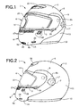
- a full-face-type helmet 1 serving also as a jet-type helmet is made up of a full- ⁇ " face-type cap-shaped head protecting body 2, a shield plate 4, and a pair of right and left chin straps (not shown).
- the full-face-type cap-shaped head protecting body 2 is to be worn on the head of a helmet wearer, e.g., the rider of a motor cycle, and serves as a jet-type head protecting body as well.
- the shield plate 4 can open/close a window opening 3 formed in the front surface of the full-face-type head protecting body 2 to oppose the portion between the forehead and chin of the wearer (i.e., almost the central portion of the face).
- the chin straps are attached to the inner surface portions of the full-face-type head protecting body 2.
- the head protecting body 2 has a main cap portion 5 and a subsidiary cap portion 6.
- the main cap portion 5 can have almost the same shape as that of the cap portion of a jet-type helmet.
- the subsidiary cap portion 6 is attached to the main cap portion 5 on the right and left sides with a pair of right and left attaching screws 7 serving as axial support means, so as to be reciprocally pivotal. Accordingly, a large window 8 is formed in the main cap portion 5 to be defined by a large notch extending upward from the lower end of the front surface of the main cap portion 5.
- the subsidiary cap portion 6 has a chin cover 6a and a pair of right and left ears 6b. The chin cover 6a is arcuated to expand forward.
- the ears 6b extend from the right and left ends of the chin cover 6a and are axially supported on the right and left sides of the main cap portion 5 with a pair of right and left attaching screws 7 to be reciprocally movable.
- the subsidiary cap portion 6 is formed with a large window 15 defined by a large notch extending downward from the upper end of its front surface.
- the subsidiary cap portion 6 pivots downward with respect to the main cap portion 5 to be located at the lower position (the state shown in Figs. 1 and 2), it serves as a chin covering means for covering the wearer's chin to close the lower portion of the window 8.
- the upper portion of the window 8 defines the window opening 3.
- the window opening 3 is formed of a region surrounded by the rim of the window 8 of the main cap portion 5 and the rim of the window 15 of the subsidiary cap portion 6.
- the shield plate 4 can be made of a transparent or translucent hard material such as polycarbonate or another type of hard synthetic resin.
- the shield plate 4 is reciprocally pivotally attached to the subsidiary cap portion 6 at the right and left sides with a pair of right and left attaching screws 9 serving as axial support means.
- the shield plate 4 closes the window opening 3 at the backward position (i.e., the lower position); and opens the window opening 3 at the forward, position (i.e., the upper position).
- the main cap portion 5 can be made up of a jet-type outer shell 11, a rim member 12 having a substantially U-shaped section, and a backing member (not shown) for the main cap portion.
- the outer shell 11 forms the outer wall of the main cap portion 5.
- the rim member 12 has a substantially E-shaped section at the upper end portion of the window 8.
- the rim member 12 has a substantially U-shaped section at the reminding portion of the window 8 except the upper end portion and is fixed to the outer shell 11 throughout the end portion of the outer shell 11 with an adhesive or the like.
- the backing member is brought into contact with the outer shell 11 to be fixed to it in contact with the inner surface of the outer shell 11 with an adhesive or the like.
- the outer shell 11 can be made of a composite material. More specifically, the outer shell 11 can be formed by lining the inner surface of a strong shell body made of a hard synthetic resin, e.g., FRP, with a flexible sheet such as an unwoven fabric. As is conventionally known, a portion of the rim member 12 having the substantially U-shaped section can be made of a soft synthetic resin such as foamed vinyl chloride or synthetic rubber. A portion of the rim member 12 having the substantially E-shaped section can be made of an elastic material with high flexibility such as synthetic rubber.
- a soft synthetic resin such as foamed vinyl chloride or synthetic rubber.
- a portion of the rim member 12 having the substantially E-shaped section can be made of an elastic material with high flexibility such as synthetic rubber.
- the backing member for the main cap portion can be constituted by an impact absorbing liner for the main cap portion, attached to the inner surface of the outer shell 11 for the main cap portion with an adhesive or the like, and a blockish inside pad for the main cap portion and a backing cover for the main cap portion which are sequentially attached to cover substantially the inner surface of the impact absorbing liner.
- the impact absorbing liner for the main cap portion can be made of a material with appropriate rigidity and plasticity such as foamed polystyrene or another synthetic resin.
- the blockish inside pad for the main cap portion can be made of one or a plurality of elastic materials with high flexibility such as urethane foam or another synthetic resin, and a porous unwoven fabric covering the inner and outer surfaces of the elastic material(s) to form a bag.
- the backing cover for the main cap portion can be made of a porous unwoven fabric formed by laminating layers, consisting of an elastic material with high flexibility such as urethane foam or another synthetic resin, on the surface opposing the impact absorbing liner for the main cap portion.
- the subsidiary cap portion 6 can be made up of an outer shell 14, a rim member 16 having a substantially E-shaped section, and a backing member (not shown) for the subsidiary cap portion.
- the outer shell 14 forms the outer wall of the subsidiary cap portion 6.
- the rim member 16 is fixed to part (i.e., the end portion of the window 15) of the end portion of the outer shell 14 with an adhesive or the like.
- the backing member for the subsidiary cap portion is brought into contact with the outer shell 14 to be fixed to it in contact with the inner surface of the outer shell 14 with an adhesive or the like.
- the outer shell 14 and the rim member 16 having the substantially E-shaped section can be made of the same materials as those described above concerning the outer shell 11 for the main cap portion and the rim member 12 having substantially the E-shaped section.
- a pair of right and left cover members 17 for externally covering the pair of right and left attaching screws 7 are attached to the outer shell 14 to be reciprocally pivotal about their front edge portions as the fulcrums. When the cover members 17 are outwardly pivoted forward through about 90°, the heads of the attaching screws 7 are exposed. Inversely, when the cover members 17 are pivoted backward, the heads of the attaching screws 7 are covered by the cover members 17, as shown in Figs. 1 to 3.
- the backing member for the subsidiary cap portion can be constituted by an impact absorbing liner for the subsidiary cap portion, and a backing cover for the subsidiary cap portion, attached to the inner surface of the impact absorbing liner to substantially cover it.
- the impact absorbing liner for the subsidiary cap portion is attached to the inner surface of the outer shell 14 for the subsidiary cap portion with an adhesive or the like, and can be made of a material with appropriate rigidity and plasticity such as foamed polyurethane rubber or another synthetic resin.
- the backing cover for the subsidiary cap portion can be made of synthetic leather or another cloth made of a synthetic resin such as vinyl chloride resin, or another fabric.
- a pair of right and left subsidiary cap portion locking mechanisms 21 are incorporated in the head protecting body 2.
- Each of the pair of subsidiary cap portion locking mechanisms 21 has a function of locking the subsidiary cap portion 6 at the lower position with the head protecting body 2, as is dearly shown in Fig. 4.
- the pair of subsidiary cap portion locking mechanisms 21 are unlocked by a common release button 22 serving as an unlocking means or member.
- the release button 22 is held by a button holding mechanism 20 serving as an unlocking member holding mechanism at substantially the central portion of the subsidiary cap portion 6 (i.e., a portion opposing the distal end of the wearer's chin) to be linearly, reciprocally slidable.
- the button holding mechanism 20 is constituted by the outer shell 14 for the subsidiary cap portion, and a button holding member 23.
- the button holding member 23 is made of an appropriate material such as a synthetic resin, e.g., polyacetal resin or ABS resin.
- the button holding member 23 has a member main body 25.
- the member main body 25 has an elongated hole 24 extending at substantially the central portion of its upper surface in the back-and-forth direction, and forms a substantially box-like lid.
- a pair of left and right substantially V-shaped attached pieces 26a and 26b are formed on the left and right sides of the member main body 25 by, e.g., monolithic molding.
- the attached pieces 26a and 26b respectively have screw engaging holes 27.
- a guide 30 is formed near the front end of the upper surface of the member main body 25 by, e.g., monolithic molding.
- the guide 30 has a pair of left and right arcuated pieces 29a and 29b extending outwardly to the left and right, respectively.
- a pair of left and right subsidiary guide plates 31a and 31b are formed on the front end face of the member main body 25 by, e.g., monolithic molding.
- a pair of left and right attaching bosses 33a and 33b for attaching the button holding member 23 are formed at substantially the central portion of the outer shell 14 for the subsidiary cap portion (i.e., a portion opposing the distal end of the wearer's chin) by, e.g., monolithic molding.
- a finger-inserting aperture 34 is formed between the pair of attaching bosses 33a and 33b.
- the release button 22 is formed of an appropriate material such as a synthetic resin, e.g., nylon 6 or ABS resin, to have a substantially blockish shape.
- a finger-inserting notched portion 28 is formed in one half of the lower surface of the release button 22.
- the notched portion 28 forms, in the release button 22, a press surface 28a (i.e., a surface substantially perpendicularly intersecting the aperture 34) used for pressing the release button 22 with a finger.
- a columnar portion 35 having a screw hole 36 is formed on substantially the central portion of the upper surface of the release button 22 by, e.g., monolithic molding.
- a pair of left and right substantially L-shaped arms 37a and 37b, and a protrusion 38, all of which extend from the columnar portion 35, are formed on the upper surface of the release button 22 by, e.g., monolithic molding.
- a wire attaching member 39 serving as a wire body attaching member attached and fixed to the release button 22 is formed of an appropriate material such as a synthetic resin, e.g., nylon 6 or ABS resin, to have a substantially platelike shape.
- An elongated hole 40 extending in the back-and-forth direction is formed at substantially the central portion of the attaching member 39.
- a substantially semicircular wire engaging portion 71 is formed on a surface of the attaching member 39 opposite to the outer shell 14 by, e.g., monolithic molding, to be near the rear end of the elongated hole 40.
- a pair of left and right projecting ridges 72a and 72b are formed on the left and right sides of the wire engaging portion 71 by, e.g., monolithic molding.
- the release button 22 is accommodated in the button holding mechanism 20, constituted by the outer shell 14 for the subsidiary cap portion and the button holding member 23, to be linearly reciprocally slidable.
- the release button 22 is fitted in the button holding member 23 to be linearly reciprocally slidable.
- the columnar portion 35, the pair of left and right arms 37a and 37b, and the protrusion 38 of the release button 22 are inserted in the elongated hole 24 of the button holding member 23.
- the pair of arms 37a and 37b are held to be linearly reciprocally slidable along the left and right rims of the elongated hole 24.
- the right and left side surfaces and upper surface of the release button 22 are also held to be linearly reciprocally slidable along the left and right inner surfaces and lower surface of the member main body 25 of the button holding member 23.
- the button holding member 23 fitted with the release button 22 is attached and fixed to the outer shell 14 for the subsidiary cap portion.
- a pair of left and right attaching screws 73a and 73b inserted in the screw engaging holes 27 of the attached pieces 26a and 26b are screwed and fixed in the pair of left and right attaching bosses 33a and 33b of the outer shell 14 for the subsidiary cap portion, attaching and fixing the member 23.
- the release button 22 is reciprocally slidable with respect to the button holding member 23 in directions indicated by arrows A and B in Figs. 4 and 7.
- the wire attaching member 39 is attached and fixed to the release button 22.
- An attaching screw 75 is inserted in a washer 74 and the elongated hole 40 of the wire attaching member 39, and the attaching screw 75 is then screwed and fixed in the screw hole 36 of the columnar portion 35 of the release button 22, thereby attaching and fixing the member 39.
- the washer 74 is placed on the wire engaging portion 71 and the pair of left and right projecting ridges 72a and 72b of the wire attaching member 39.
- the wire attaching member 39 is placed on the pair of left and right arms 37a and 37b and the protrusion 38 of the release button 22.
- the wire attaching member 39 is linearly moved back and forth by utilizing the elongated hole 40, so that the attaching position in the back-and-forth direction of the wire attaching member 39 with respect to the release button 22 can be adjusted.
- the tractive wire 32 This adjusts the tautness of the tractive wire 32 to remove the unnecessary slack of the tractive wire 32.
- the left and right portions of the tractive wire 32 that are directly continuous to the substantially U-shaped intermediate portion 32c are wound on the pair of left and right arcuated pieces 29a and 29b.
- the tractive wire 32 is used commonly by the pair of right and left subsidiary cap portion locking mechanisms 21. More specifically, the tractive wire 32 has a pair of left and right wire portions 32a and 32b continuous to the two ends of the U-shaped intermediate portion 32c.
- the wire portion 32a (to be referred to as the "tractive wire 32a” hereinafter) on the right side (i.e., on right side of the front surface of the helmet 1; this applies to the following description) is used by the right subsidiary cap portion locking mechanism 21.
- the wire portion 32b (to be referred to as the “tractive wire 32b” hereinafter) on the left side (i.e., on left side of the front surface of the helmet 1; this applies to the following description) is used by the left subsidiary cap portion locking mechanism 21. Since the right and left subsidiary cap portion locking mechanisms 21 are symmetric, a description will be made concerning the right subsidiary cap portion locking mechanism 21 hereinafter with reference to Figs. 4 to 6, and a description on the left subsidiary cap portion locking mechanism 21 will be omitted.
- an attaching base 41 made of an appropriate material such as a metal like stainless steel, or a synthetic resin like ABS resin, is attached and fixed to the inner surface of the right ear 6b of the subsidiary cap portion 6 with an attaching screw 42.
- a lock lever 43 serving as a movable locking means or member is axially supported on the attaching base 41 with an attaching screw 44 to be reciprocally pivotal.
- a stopped portion 45 made of a flat-plate-like upright portion is integrally formed on one end portion of the lock lever 43.
- a wire attached portion 46 formed of an L-shaped upright portion is integrally formed on the other end portion of the lock lever 43.
- the wire attached portion 46 fixes the distal end portion of an attaching rod 48, the proximal end portion of which extends from the lock lever 43.
- the free end portion of the tractive wire 32a is fixed to the attaching rod 48.
- a spring retainer 49 which can have a substantially cup-like shape is formed on the attaching base 41 by monolithic molding or with an adhesive.
- the tractive wire 32a is inserted in a wire inserting hole 50 of the spring retainer 49.
- the tractive wire 32a extends through a flexible tube 52 made of an appropriate elastic material such as synthetic rubber.
- One end portion of the tube 52 is held in position by the arcuated piece 29a and subsidiary guide plate 31a of the button holding member 23, and abuts against a front end face 63 of the member main body 25.
- the other end portion of the tube 52 abuts against the spring retainer 49.
- One end portion of a tube 52 identical to the above tube 52 and used by the left subsidiary cap portion locking mechanism 21 is also held in position by the arcuated piece 29b and subsidiary guide plate 31b of the button holding member 23, and abuts against the front end face 63 of the member main body 25.
- a compression coil spring 51 through which the tractive wire 32a extends is interposed between the spring retainer 49 and the wire attached portion 46 of the lock lever 43. For this reason, the lock lever 43 is biased by the coil spring 51 to pivot counterclockwise in Fig. 4 about the attaching screw 44 as the center. Since the lock lever 43 is biased to pivot counterclockwise in Fig. 4, the release button 22 is tractively biased by the tractive wire 32a to move backward in the direction indicated by the arrow B in Figs. 4 and 7.
- the release button 22 can move forward in the direction indicated by the arrow A in Figs. 4 and 7 against the tractive biasing force of the tractive wire 32a.
- the forward moving direction A of the release button 22 forms an acute angle ⁇ with respect to a downward moving direction (i.e., a backward pivot direction about the attaching screws 7 as the fulcrum) C of the subsidiary cap portion 6, as shown in Fig. 4.
- the acute angle ⁇ is about 25°.
- this angle is preferably 0° to 60°, and more preferably 0° to 45°.
- the forward moving direction A of the release button 22 is inward (i.e., backward in Fig. 4) of the downward moving direction C of the subsidiary cap portion 6.
- this direction A need not be inward but can be outward.
- the forward moving direction A of the release button 22 is preferably inward of the downward moving direction C of the subsidiary cap portion 6.
- the acute angle ⁇ is particularly preferably 5° to 45°.
- the lock levers 43 of the right and left subsidiary cap portion locking mechanisms 21 selectively engage with the lock pins 54 depending on their pivot positions.
- Each lock lever 43 is formed with an abutting portion 43a against which the corresponding lock pin 54 abuts.
- a locking recess 62 to engage with the lock pin 54 is formed adjacent to the abutting portion 43a.
- the respective portions (i.e., the attaching bases 41, coil springs 51, lock levers 43, attaching rods 48, attaching screws 42 and 44, and the like) of the locking mechanisms 21, the release button 22, the button holding mechanism 20 (i.e., the button holding member 23, attaching bosses 33a and 33b, and the like), the wire attaching member 39, the washer 74, the attaching screws 73a, 73b, and 75, the tubes 52, the tractive wires 32a and 32b, and the like are arranged along the inner surface of the outer shell 14 for the subsidiary cap portion.
- recesses and ridge grooves for accommodating these portions are formed in the surface of the impact absorbing liner for the subsidiary cap portion that opposes the outer shell 14.
- a ventilation aperture forming member 55 for the forehead is attached to the outer surface of the forehead portion of the main cap portion 5.
- a stopper 56 for regulating the backward position of the shield plate 4 is provided to the right portion of the outer surface of the subsidiary cap portion 6.
- Various types of ventilation apertures 57, 58, and 59 are formed in the chin cover 6a of the subsidiary cap portion 6.
- an air guide plate 60 is attached to the inner surface of the chin cover 6a with attaching screws 61 so as to oppose the ventilation apertures 57. Therefore, air flowing into the head protecting body 2 through the ventilation apertures 57 is guided by the front surface of the air guide plate 60 to move upward in the head protecting body 2 along the inner surface of the shield plate 4.
- the wearer wishes to use the helmet 1 as a full-face-type helmet. If the subsidiary cap portion 6 is at the upper position, as shown in Fig. 3, the wearer pivots it downward about the attaching screws 7 as the center, thereby bringing it to the lower position shown in Figs. 1 and 2.
- the abutting portions 43a of the lock levers 43 provided to the subsidiary cap portion 6 as shown in Fig. 6 abut against the lock pins 54.
- the lock levers 43 are accordingly pressed by the lock pins 54, and pivot slightly forward clockwise in Fig. 6 about the attaching screws 44 as the fulcrum against the biasing force of the coil springs 51.
- the lock pins 54 thus ride over the abutting portions 43a of the lock levers 43, as shown in Fig. 4, to engage with the corresponding locking recesses 62.
- the subsidiary cap portion 6 is securely locked by the main cap portion 5 with the pair of right and left subsidiary cap portion locking mechanisms 21, so that the head protecting body 2 serves as the full-face-type.
- the wearer wishes to use the helmet 1 shown in Figs. 1 and 2, currently serving as the full-face-type helmet, as a jet-type helmet shown in Fig. 3.
- the wearer inserts his finger (e.g., index finger and/or middle finger) in the notched portion 28 of the release button 22 through the aperture 34 located at substantially the central portion of the outer surface of the chin cover 6a of the subsidiary cap portion 6.
- the wearer presses the press surface 28a of the release button 22 with this finger downward in the forward direction, indicated by the arrow A in Fig. 4, against the biasing force of the coil springs 51.
- the press surface 28a substantially perpendicularly intersects the forward direction A of the release button 22, the direction of the force applied by the finger onto the release button 22 substantially coincides with this forward direction A.
- the wearer simultaneously places his finger (e.g., the thumb) on substantially the central portion of the lower end of the subsidiary cap portion 6 (e.g., grabs the subsidiary cap portion 6 from the upper and lower sides with his index finger and/or middle finger inserted in the notched portion 28 and his thumb placed on substantially the central portion of the lower end of the subsidiary cap portion 6), and raises the subsidiary cap portion 6, the subsidiary cap portion 6 pivots upward about the attaching screws 7 as the fulcrum.
- the subsidiary cap portion 6 is set in the state shown in Fig. 3 through the state shown in Fig. 6.
- the head protecting body 2 serves as the jet-type.
- the tractive wires 32a and 32b are inserted in the tubes 52.
- the tractive wires 32a and 32b can be easily set not to come into substantial contact with any foreign matter other than the tubes 52. As a result, the tractive wires 32a and 32b can always move comparatively smoothly.
- These tubes 52 can be omitted if necessary. If the tubes 52 are omitted, the tractive wires 32a and 32b are preferably selected to have such a length that they extend substantially linearly between the arcuated pieces 29a and 29b of the guide plate 30 of the button holding member 23 and the spring retainers 49 of the attaching bases 41.
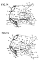
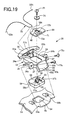
- the helmet of the second embodiment shown in Figs. 10 to 22 has substantially the same arrangement, function, and effect as those of the helmet according to the first embodiment described above shown in Figs. 1 to 9, except for the differences and respects concerning them described in the following items (1) to (7). Accordingly, in the following description, only the differences and respects concerning them described in these items (1) to (7) will be described. Portions that are common between the helmet according to the second embodiment shown in Figs. 10 and 22 and the helmet according to the first embodiment described above shown in Figs. 1 to 9 are denoted by the same reference numerals, and a description other than the differences and respects concerning them will be omitted.
- Each of the pair of right and left support plates 81 is an elongated platelike member extending in substantially the back-and-forth direction, as shown in Figs. 11 and 12, and can be made of a material similar to that described above concerning the button holding member 23.
- the support plates 81 are fixed to an outer shell 11 for a main cap portion with attaching screws 84 at their portions near the front end portions.
- the portions of the support plates 81 near the rear end portions are also fixed, together with ears 6b of the subsidiary cap portion 6, to the outer shell 11 for the main cap portion with attaching screws (i.e., axial support means) 7.
- the cover members 17 provided in the first embodiment for the attaching screws 7 are omitted in the second embodiment.
- a projection 86 to fit in a coil portion 85a provided at the central portion of a spring 85 serving as a biasing means is formed on each support plate 81 by monolithic molding or the like.
- the spring 85 serves as a torsion coil spring, and further has first and second wire portions 85b and 85c extending from the coil portion 85a in substantially the opposite directions.
- the support plate 81 is formed with a pair of spring catching projections 87 and 88 by monolithic molding or the like to engage with the first coil portion 85b.
- the first wire portion 85b is inserted between the pair of projections 87 and 88.
- a pair of right and left projections 89 serving as positioning means project from the inner surface of an outer shell 14 at each of the pair of right and left ears 6b of the subsidiary cap portion 6.
- the second wire portion 85c of the spring 85 is bent almost arcuatedly.
- the positioning projection 89 serving also as the spring hook means presses against the arcuated second wire portion 85c.
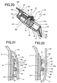
- the support plates 81 are formed with a pair of right and left recesses 90 serving as positioning means.
- the positioning projections 89 lightly engage or fit with the recesses 90, as shown in Fig. 21, to prohibit the subsidiary cap portion 6 from moving with a comparatively small action force.
- the upward biasing force for the subsidiary cap portion 6 generated by the springs 85 can be entirely or partially reduced by this engagement or fitting.
- the subsidiary cap portion 6 located at the lower position is not only locked at the lower position by the pair of right and left subsidiary cap portion locking mechanisms 21, but is lightly held in position at the lower position by the recess-projection engagement of the positioning means 89 and 90, 50 that its forward movement is prohibited by a comparatively small action force.
- the springs 85 bias the subsidiary cap portion 6 upward (i.e., in the forward direction) through the positioning projections 89, so that the subsidiary cap portion 6 is raised smoothly when the recess-projection engagement is canceled. Furthermore, since the springs 85 bias the subsidiary cap portion 6 clockwise in Figs.
- Each support plate 81 is formed with a substantially semicylindrical stopper projection 91 by monolithic molding or the like.
- the positioning projection 89 engages with the stopper projection 91, as shown in Fig. 22.
- the support plate 81 is also formed with a stopper projection 92, having an inclined surface, adjacent to the stopper projection 91 by monolithic molding or the like. While the subsidiary cap portion 6 moves from the lower position to immediately before the upper position, the positioning projection 89 gradually rides over the inclined surface of the stopper projection 92. Accordingly, while the subsidiary cap portion 6 moves from the lower position to immediately before the upper position, the positioning projection 89 rides over the inclined surface of the stopper projection 92 and thereafter passes it. As a result, as shown in Fig. 22, the positioning projection 89 (and also the subsidiary cap portion 6) is completely prohibited by the stopper projection 91 from moving further forward and by the stopper projection 92 from moving backward, with a comparatively small action force.
- the finger putting plate 83 having a substantially vertical finger putting surface 83a is formed on the rear end face of a member main body 25 of the button holding member 23 of the button holding mechanism 20 by monolithic molding or the like.
- the finger putting surface 83a has projecting ridges 93a, 93b, and 94 at its left and right side end portions and lower end portion, respectively.
- the projecting ridges 93a, 93b, and 94 form a substantially U-letter shape as a whole.
- the outer shell 14 is formed with an expansion 95 at substantially the central portion of the lower end of the chin cover 6a of the subsidiary cap portion 6 to slightly expand forward to conform to the shape of the finger putting plate 83.
- the attaching base 41 corresponding to the attaching base 41 of the first embodiment is constituted by the main attaching base 41 and the subsidiary attaching base 82, as shown in Figs. 13 and 17.
- the subsidiary attaching base 82 may be made of the same material as that described above concerning the attaching base 41.
- the main attaching base 41 is preferably made of a metal and the subsidiary attaching base 82 is preferably made of a synthetic resin.
- the main attaching base 41 can have a flat platelike shape.
- the main attaching base 41 is formed with a pair of boss inserting holes 101a and bib, a rivet inserting hole 102, a boss inserting hole 103, and a screw inserting hole 104.
- the spring retainer 49 is formed on the attaching base 41.
- a spring retainer 49 is formed on the subsidiary attaching base 82 by monolithic molding or the like.
- the subsidiary attaching base 82 has a step 82a at substantially its central portion, and a front plate 82b and a rear plate 82c on the two sides of the step 82a.
- the rear plate 82c is formed with a pair of screw inserting bosses 105a and 105b and the spring retainer 49 by monolithic molding or the like.
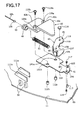
- Spherical bodies 106 made of a metal or the like are fixed to the free ends of the pair of right and left tractive wires 32a and 32b, as shown in Figs. 13 and 17.
- a substantially semicircular engaging notch 107 is formed on the free end of a wire attached portion 46 of each lock lever 43.
- a substantially circular engaging aperture 108 is formed in a lever main body 109 of the lock lever 43, on a side of the engaging notch 107 opposite to the outer shell 14.Portions near the free ends of the tractive wires 32a and 32b are inserted between the lever main bodies 109 of the lock levers 43 and the wire attached portions 46 from above, and the spherical bodies 106 are fitted in the engaging notches 107 and engaging apertures 108, thereby fixing the free ends of the tractive wires 32a and 32b to the lock levers 43.
- a pair of upper and lower projecting ridges 111a and 111b extending substantially horizontally are formed on each of the left and right sides of the chin cover 6a of the subsidiary cap portion 6, as shown in Figs. 13 and 17, by monolithic molding or the like.
- a pair of upper and lower screwing bosses 112a and 112b, a positioning boss 113, and a screwing boss 114 are formed on each of the left and right sides of the chin cover 6a of the subsidiary cap portion 6 by monolithic molding or the like, to be adjacent to the projecting ridges 111a and 111b.
- each of the tractive wires 32a and 32b is interposed between the corresponding pair of projecting ridges 111a and 111b so that it is positioned to a certain degree.
- a rivet 116 inserted in a rivet engaging hole 115, formed in the lever main body 109 of the lock lever 43, and the rivet engaging hole 102 in the main attaching base 41 pivotally fixes the lock lever 43 to the attaching base 41.
- the positioning boss 113 is fitted in the boss inserting hole 103 of the attaching base 41, and the front surface of the attaching base 41 is abutted against the distal end face of the screwing boss 114. After that, a screw 117 is inserted in the screw inserting hole 104 of the attaching base 41 and screwed into the screwing boss 114, thereby fixing the attaching base 41 to the inner surface of the outer shell 14.
- the pair of screwing bosses 112a and 112b are inserted in the boss inserting holes 101a and 101b of the attaching base 41.
- the distal end faces of the bosses 112a and 112b abut against a surface, on the outer shell 14 side, of the front plate 82b of the subsidiary attaching base 82.
- a pair of upper and lower screws 118a and 118b are inserted in the screw inserting bosses 105a and 105b, and screwed into the screwing bosses 112a and 112b, thereby fixing the subsidiary attaching base 82 and main attaching base 41 to the inner surface of the outer shell 14.
- a gap 121 is defined by the main attaching base 41, the lock lever 43, and the rear plate 82c of the subsidiary attaching base 82. Accordingly, the subsidiary attaching base 82 serves as a gap defining member as well.
- a cover member (not shown) for covering the outer surface and, if necessary, the inner surface as well, of a portion of the outer shell 11 near its lower end may be provided, and the lock pins 54 may be fixed to the cover member.
- This cover member can be made of the same material as that described above concerning the button holding member 23.
- the pair of right and left subsidiary attaching bases 82 are formed on the right and left sides of the chin cover 6a of the subsidiary cap portion 6. Accordingly, the gap 121 is formed on each of the right and left sides to form a pair.
- a pair of right and left portions of the outer shell 11, near the lower end, of the main cap portion 5 are inserted in the pair of right and left gaps 121, respectively.
- This insertion amount is the maximum when the subsidiary cap portion 6 is at the lower position shown in Figs. 13 and 14, and decreases gradually as the subsidiary cap portion 6 moves forward from the lower position shown in Figs. 13 and 14 to the intermediate position shown in Fig. 15 which is slightly above the lower position.
- the pair of left and right tubes 52 are provided to extend the pair of left and right tractive wires 32a and 32b therethrough.
- such tubes 52 are omitted. Therefore, the tractive wires 32a and 32b extend substantially linearly between arcuated pieces 29a and 29b of a guide 30 of the button holding member 23 and the spring retainers 49 of the subsidiary attaching bases 41.
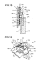
- the wire attaching member 39 of the button holding mechanism 20 is arranged upside down from the state of the first embodiment, as shown in Figs. 18 and 19. Accordingly, a wire engaging portion 71 and a pair of left and right projecting ridges 72a and 72b are formed on the surface of the wire attaching member 39 on the outer shell 14 side.
- a pair of left and right arms 37a and 37b of a release button (i.e., unlocking member) 22 are fitted between the pair of left and right projecting ridges 72a and 72b of the wire attaching member 39.
- a projection formed by the pair of left and right arms 37a and 37b (the intermediate portion of this projection, i.e., the portion between the pair of arms 37a and 37b, forms a notch) is fitted in a recess formed between the pair of left and right projecting ridges 72a and 72b through recess-projection fitting, to be linearly, reciprocally slidable.
- the wire engaging portion 71 of the wire attaching member 39 is inserted between the pair of left and right arms 37a and 37b.
- a U-shaped intermediate portion 32c of the tractive wire 32 is hooked on the wire engaging portion 71, and abuts against the right and left sides of a columnar portion 35 of the release button 22. Accordingly, the intermediate portion 32c is securely sandwiched from the two sides by the proximal end portions of the pair of left and right arms 37a and 37b of the release button 22 and a surface of the wire attaching member 39 on the outer shell 14 side.
- the pair of arms 37a and 37b of the release button 22 linearly, reciprocally slide along the rim of the elongated hole 24 of the button holding member 23.
- the pair of projecting ridges 72a and 72b of the wire attaching member 39 linearly, reciprocally slide along the rim of an elongated hole 24 corresponding to their counterpart of the first embodiment.
- the chin cover 6a of the subsidiary cap portion 6 is formed with the pair of right and left comparatively large ventilation apertures 59.
- the right and left ventilation aperture pairs 59 each consisting of comparatively small two, front and rear ventilation apertures, are formed.
- the direction perpendicularly intersecting the press surface 28a of the release button 22 substantially coincides with the forward moving direction A of the release button 22.
- an acute angle ⁇ ' formed by the direction perpendicularly intersecting the press surface 28a of the release button 22 with respect to the downward moving direction C of the subsidiary cap portion 6 may have the same angular range as that described concerning the acute angle ⁇ .
Landscapes
- Helmets And Other Head Coverings (AREA)
Applications Claiming Priority (4)
| Application Number | Priority Date | Filing Date | Title |
|---|---|---|---|
| JP21853398 | 1998-07-16 | ||
| JP21853398 | 1998-07-16 | ||
| JP12450299A JP4428754B2 (ja) | 1998-07-16 | 1999-04-30 | ヘルメット |
| JP12450299 | 1999-04-30 |
Publications (2)
| Publication Number | Publication Date |
|---|---|
| EP0972461A1 EP0972461A1 (en) | 2000-01-19 |
| EP0972461B1 true EP0972461B1 (en) | 2003-10-01 |
Family
ID=26461183
Family Applications (1)
| Application Number | Title | Priority Date | Filing Date |
|---|---|---|---|
| EP19990113729 Expired - Lifetime EP0972461B1 (en) | 1998-07-16 | 1999-07-13 | Helmet |
Country Status (3)
| Country | Link |
|---|---|
| EP (1) | EP0972461B1 (ja) |
| JP (1) | JP4428754B2 (ja) |
| DE (1) | DE69911693T2 (ja) |
Families Citing this family (20)
| Publication number | Priority date | Publication date | Assignee | Title |
|---|---|---|---|---|
| KR100341452B1 (ko) * | 1999-12-06 | 2002-06-21 | 홍완기 | 헬멧의 턱보호대장치 |
| IT1316350B1 (it) * | 2000-02-07 | 2003-04-10 | Antonio Locatelli | Casco integrale apribile |
| KR100339064B1 (ko) * | 2000-06-16 | 2002-05-31 | 홍완기 | 안전헬멧 |
| ES1047020Y (es) * | 2000-09-05 | 2001-07-16 | Tomas Manuf | Dispositivo de bloqueo para mentoneras abatibles de cascos de motocicleta. |
| ES2212696B1 (es) * | 2001-09-21 | 2005-05-16 | Marketing Active Sport Makets S.L. | Mecanismo de retencion para mentoneras de cascos. |
| DE10156808A1 (de) * | 2001-11-20 | 2003-05-28 | Uvex Sports Gmbh & Co Kg | Motorrad-Integralhelm |
| EP1500340B1 (en) * | 2003-07-25 | 2007-07-04 | OPTICOS S.r.l. | Device for unlocking the rotation of a crash-helmet chin guard |
| DE102005001804A1 (de) * | 2004-10-04 | 2006-07-27 | Schuberth Engineering Ag | Sturzhelm |
| DE102004048839B4 (de) | 2004-10-04 | 2006-07-20 | Schuberth Werk Gmbh | Integralhelm |
| FR2881625B1 (fr) * | 2005-02-04 | 2007-09-07 | Cbm Distrib Entpr Unipersonnel | Casque de protection notamment pour motocycliste |
| KR100649945B1 (ko) * | 2005-12-06 | 2006-11-27 | 주식회사 홍진에이치제이씨 | 턱 보호대를 가진 헬멧 |
| JP4895647B2 (ja) | 2006-03-17 | 2012-03-14 | 株式会社Shoei | ヘルメット |
| IT1393839B1 (it) * | 2009-04-30 | 2012-05-11 | Suomy S P A | Casco di protezione di tipo apribile, particolarmente per uso motociclistico e/o automobilistico, con dispositivo di aggancio/sgancio della mentoniera perfezionato. |
| KR101156622B1 (ko) | 2010-03-11 | 2012-06-14 | 주식회사 홍진에이치제이씨 | 다용도 헬멧 |
| EP2762021B1 (en) * | 2011-09-27 | 2017-07-12 | Hjc Corp. | Device for opening/closing a chin protector and helmet comprising the same |
| ES2635076B1 (es) * | 2016-04-01 | 2018-07-06 | Oscar RUBIANO MONTERO | Casco modular para motorista con cierre automático de mentonera. |
| GB2552547A (en) * | 2016-07-29 | 2018-01-31 | Smallwood Ioan | A helmet |
| JP6842993B2 (ja) * | 2017-05-22 | 2021-03-17 | 株式会社Shoei | ヘルメット |
| KR102584882B1 (ko) * | 2022-02-24 | 2023-10-06 | (주)에이치제이씨 | 헬멧 |
| JP2023129879A (ja) * | 2022-03-07 | 2023-09-20 | 株式会社Shoei | ヘルメット |
Family Cites Families (4)
| Publication number | Priority date | Publication date | Assignee | Title |
|---|---|---|---|---|
| FR2593035B1 (fr) * | 1986-01-21 | 1988-06-10 | Chaise Francois | Systeme aerodynamique et antibuee de coque et d'ecran de vision d'un casque de protection. |
| DE4040172A1 (de) * | 1990-12-15 | 1992-06-17 | Bayerische Motoren Werke Ag | Schutzhelm |
| DE59201063D1 (de) | 1991-06-08 | 1995-02-09 | Bayerische Motoren Werke Ag | Integralschutzhelm. |
| DE19612724C2 (de) | 1996-03-29 | 2000-05-25 | Baehr Gmbh & Co Kg | Integralschutzhelm |
-
1999
- 1999-04-30 JP JP12450299A patent/JP4428754B2/ja not_active Expired - Fee Related
- 1999-07-13 EP EP19990113729 patent/EP0972461B1/en not_active Expired - Lifetime
- 1999-07-13 DE DE69911693T patent/DE69911693T2/de not_active Expired - Lifetime
Also Published As
| Publication number | Publication date |
|---|---|
| DE69911693T2 (de) | 2004-08-05 |
| JP2000096334A (ja) | 2000-04-04 |
| EP0972461A1 (en) | 2000-01-19 |
| DE69911693D1 (de) | 2003-11-06 |
| JP4428754B2 (ja) | 2010-03-10 |
Similar Documents
| Publication | Publication Date | Title |
|---|---|---|
| US6226803B1 (en) | Helmet | |
| EP0972461B1 (en) | Helmet | |
| EP1834535B1 (en) | Helmet | |
| EP2550884B1 (en) | Visor attachment mechanism in a helmet | |
| EP0473857B1 (en) | Helmet | |
| US5546610A (en) | Fastening system for fastening a face-protection sheild and/or hearing protection caps to a work helmet | |
| JP2668322B2 (ja) | 乗車用ヘルメット | |
| US6138284A (en) | Helmet | |
| EP0294676B1 (en) | Shield mounting assembly for a safety helmet | |
| US20100050323A1 (en) | Hockey helmet comprising an occipital adjustment mechanism | |
| US6256797B1 (en) | Helmet and method of removing the same | |
| EP0504518A1 (en) | Helmet with visor | |
| KR20130036165A (ko) | 헬멧 | |
| KR930000360B1 (ko) | 헬멧 | |
| JP2000096334A5 (ja) | ||
| JPS59187608A (ja) | ヘルメツト帽 | |
| EP0395845A1 (en) | Crash-helmet, in particular for motorcyclists | |
| JP3008397B2 (ja) | ヘルメットの内装体 | |
| JP4781007B2 (ja) | ヘルメット | |
| JP2990688B2 (ja) | ヘルメット | |
| JP3063079B2 (ja) | ヘルメットのシールド取付構造 | |
| KR101622607B1 (ko) | 헬멧 | |
| JP3010621B2 (ja) | ヘルメット | |
| JPH10204717A (ja) | ヘルメット | |
| JPH11172517A (ja) | ヘルメット |
Legal Events
| Date | Code | Title | Description |
|---|---|---|---|
| PUAI | Public reference made under article 153(3) epc to a published international application that has entered the european phase |
Free format text: ORIGINAL CODE: 0009012 |
|
| AK | Designated contracting states |
Kind code of ref document: A1 Designated state(s): DE FR IT |
|
| AX | Request for extension of the european patent |
Free format text: AL;LT;LV;MK;RO;SI |
|
| 17P | Request for examination filed |
Effective date: 20000627 |
|
| AKX | Designation fees paid |
Free format text: DE FR IT |
|
| 17Q | First examination report despatched |
Effective date: 20020516 |
|
| GRAH | Despatch of communication of intention to grant a patent |
Free format text: ORIGINAL CODE: EPIDOS IGRA |
|
| GRAS | Grant fee paid |
Free format text: ORIGINAL CODE: EPIDOSNIGR3 |
|
| GRAA | (expected) grant |
Free format text: ORIGINAL CODE: 0009210 |
|
| AK | Designated contracting states |
Kind code of ref document: B1 Designated state(s): DE FR IT |
|
| REF | Corresponds to: |
Ref document number: 69911693 Country of ref document: DE Date of ref document: 20031106 Kind code of ref document: P |
|
| ET | Fr: translation filed | ||
| PLBE | No opposition filed within time limit |
Free format text: ORIGINAL CODE: 0009261 |
|
| STAA | Information on the status of an ep patent application or granted ep patent |
Free format text: STATUS: NO OPPOSITION FILED WITHIN TIME LIMIT |
|
| 26N | No opposition filed |
Effective date: 20040702 |
|
| PGFP | Annual fee paid to national office [announced via postgrant information from national office to epo] |
Ref country code: DE Payment date: 20130729 Year of fee payment: 15 |
|
| PGFP | Annual fee paid to national office [announced via postgrant information from national office to epo] |
Ref country code: FR Payment date: 20130730 Year of fee payment: 15 |
|
| PGFP | Annual fee paid to national office [announced via postgrant information from national office to epo] |
Ref country code: IT Payment date: 20130729 Year of fee payment: 15 |
|
| REG | Reference to a national code |
Ref country code: DE Ref legal event code: R119 Ref document number: 69911693 Country of ref document: DE |
|
| REG | Reference to a national code |
Ref country code: FR Ref legal event code: ST Effective date: 20150331 |
|
| PG25 | Lapsed in a contracting state [announced via postgrant information from national office to epo] |
Ref country code: IT Free format text: LAPSE BECAUSE OF NON-PAYMENT OF DUE FEES Effective date: 20140713 Ref country code: DE Free format text: LAPSE BECAUSE OF NON-PAYMENT OF DUE FEES Effective date: 20150203 |
|
| REG | Reference to a national code |
Ref country code: DE Ref legal event code: R119 Ref document number: 69911693 Country of ref document: DE Effective date: 20150203 |
|
| PG25 | Lapsed in a contracting state [announced via postgrant information from national office to epo] |
Ref country code: FR Free format text: LAPSE BECAUSE OF NON-PAYMENT OF DUE FEES Effective date: 20140731 |