Technical Field
The present invention relates to a helmet which
has a cap-shaped head protecting body, worn by the helmet
wearer such as the rider of a motor cycle to protect
his/her head, and having a cap-shaped main cap portion and
a subsidiary cap portion attached to the main cap portion
to be substantially vertically movable so as to
selectively cover the chin of the helmet wearer.
Background of the Invention
As vehicle helmets worn by the rider of a motor
cycle or the like, a full-face-type helmet and a jet-type
helmet are conventionally known. In the full-face-type
helmet, a chin cover for covering the chin of the helmet
wearer is integrally formed with the head protecting body.
In the jet-type helmet, no chin cover is formed on the
head protecting body so as to expose the face of the
helmet wearer almost entirely. Another full-face-type
helmet (to be referred to as a "full-face-type helmet
serving also as a jet-type helmet" hereinafter) is also
conventionally known. In this full-face-type helmet, the
head protecting body is formed of a main cap portion
having almost the same shape as that of the head
protecting body of a jet-type helmet, and a subsidiary cap
portion attached to the main cap portion to be
substantially vertically pivotal so as to selectively
cover the chin of the helmet wearer, so that the helmet
can have the functions of both a full-face-type helmet and
a jet-type helmet.
In the conventional full-face-type helmet serving
also as the jet-type helmet, when the subsidiary cap
portion is at the lower position, it serves as a chin
covering means. When the subsidiary cap portion is at the
upper position, a large window formed in the main cap
portion is opened, and the head protecting body
accordingly has no chin covering means, in the same manner
as in the jet-type helmet. When the wearer wearing the
full-face-type helmet serving also as the jet-type helmet
is driving a motor cycle at high speed, the helmet is worn
with its subsidiary cap portion being lowered to the lower
position, in order to prevent a large wind pressure from
acting on the wearer's chin and its vicinity. The helmet
is provided with a subsidiary cap portion locking
mechanism for locking the subsidiary cap portion at the
lower position with respect to the main cap portion, so
that the subsidiary cap portion does not undesirably move
upward by a large impact or wind pressure during highspeed
driving. The subsidiary cap portion is provided with
an unlocking means or member in order to unlock the
subsidiary cap portion locked at the lower position by the
subsidiary cap portion locking mechanism.
Such a conventional full-face-type helmet serving
also as the jet-type helmet is disclosed in European
Patent No. 518,178 as well. In the helmet disclosed in
this reference (to be referred to as "the first known
helmet" hereinafter), when a release lever serving as the
unlocking member is pressed for unlocking, a force which
moves the subsidiary cap portion from the lower position
to the upper position automatically acts on the subsidiary
cap portion. In other words, when the release lever is
pressed upward, the subsidiary cap portion locked at the
lower position is unlocked. Therefore, when the release
lever is pressed upward to unlock the locked subsidiary
cap portion, the subsidiary cap portion locked by the
locking mechanism is unlocked. Also, the subsidiary cap
portion can be started to move from the lower position to
the upper position by only successively pressing the
release lever. Hence, the wearer can unlock the locked
subsidiary cap portion and move the unlocked subsidiary
cap portion upward quickly and continuously by only
pressing the release lever.
In the first known helmet as described above,
assume that, while the wearer drives the motor cycle at
high speed, for example, he erroneously presses the
release lever upward so as to slightly move a shield plate
(attached to the subsidiary cap portion to be able to
open/close the window opening formed in the front surface
of the head protecting body of the helmet), so that the
window opening closed by the shield plate may be slightly
opened. Alternatively, assume that a foreign matter
accidentally abuts against the release lever from below.
Then, the subsidiary cap portion locked at the lower
position is unlocked, and undesirably moves upward from
the lower position for a certain degree. A large wind
pressure then can directly act on the wearer's chin,
causing inconveniences for the wearer in driving the motor
cycle.
In the first known helmet as described above, when
an operation lever connected to the release lever through
a wire causes a movable locking member made of a spring
member to move forward against the spring force, the
locking mechanism is unlocked. In spite that the structure
of the mechanism for unlocking the subsidiary cap portion
locked by the locking mechanism is not very simple, the
subsidiary cap portion might not be unlocked or inversely
locked by the locking mechanism quickly and smoothly.
The conventional full-face-type helmet serving
also as the jet-type helmet, as described above, is
disclosed in German Patent Laid-Open No. 19,612,724 as
well. In the helmet (to be referred to as "the second
known helmet" hereinafter) disclosed in this reference,
when the release tap serving as the unlocking means is
pressed for unlocking, a force opposite to a force that
moves the subsidiary cap portion from the lower position
to the upper position acts on the subsidiary cap portion.
In other words, when the release tap is pressed downward,
the subsidiary cap portion locked at the lower position is
unlocked. Even when the release tap is continuously
pressed, it is not sufficient to move the subsidiary cap
portion from the lower position to the upper position.
Therefore, when the wearer is driving the motor cycle at
high speed, the subsidiary cap portion does not move
upward from the lower position erroneously or
accidentally, and accordingly large wind pressure will not
substantially, directly act on the helmet wearer's chin.
In the second known helmet as described above, the
movable locking member is constituted by an arcuated
operation lever formed with the release tap at its central
portion. The operation lever is pivotally, axially
supported on the auxiliary cap portion at the right and
left portions. Also, a pair of right and left engaging
recesses are formed in the right and left end portions of
the operation lever. When a pair of right and left lock
pins provided to the main cap portion relatively engage
with these engaging recesses, the subsidiary cap portion
is locked on the main cap portion. When the helmet wearer
holds the release tap with his fingers and moves it
downward, the operation lever pivots forward to disengage
the lock pins relatively from the engaging recesses,
thereby unlocking the locked subsidiary cap portion.
Therefore, in the second known helmet as well, in spite
that the structure of the mechanism for unlocking the
subsidiary cap portion locked by the locking mechanism is
not very simple, the subsidiary cap portion might not be
unlocked or inversely locked by the locking mechanism quickly and smoothly.
DE 40 40 172 Al discloses a helmet according to the preamble of claim 1.
Summary of the Invention
The present invention is directed to correcting
the drawbacks described above of the conventional full-face-type
helmet serving also as the jet-type helmet with
a very simple arrangement very effectively.
It is, therefore, the main object of the present
invention to provide a helmet in which, in spite that the
mechanism for unlocking the subsidiary cap portion locked
on the main cap portion with the locking mechanism is
comparatively simple, the unlocking operation and the
opposite locking operation can be performed quickly and
smoothly.
It is another object of the present invention to
provide a helmet with which when the wearer is driving a
motor cycle at high speed, the subsidiary cap portion will
not move upward from the lower position erroneously or
accidentally, and large wind pressure will not
substantially, directly act on the helmet wearer's chin.
Therefore, the present invention relates to a
helmet including a cap-shaped head protecting body to be
worn by a helmet wearer on his/her head, the head
protecting body having a main cap portion and a subsidiary
cap portion attached to the main cap portion to be
substantially vertically movable so as to selectively cover
a chin of the helmet wearer, the head protecting body being
provided with first and second locking mechanisms for respectively locking left
and right sides of the subsidiary cap portion with respect to the main cap portion
when the subsidiary cap portion is at a lower position to cover the chin,
and the head protecting body being also provided with a common unlocking
member which moves operatively in a forward moving direction being inwardly
of a downward moving direction of said subsidiary cap portion to commonly
unlock said subsidiary cap portion locked by said first and second locking
mechanisms, wherein said helmet is provided with a common tractive flexible
wire for commonly transmitting the forward movement of said unlocking member
to said first and second movable locking members of said first and second
locking mechanisms. One end portion of said wire is connected to said first
movable locking member and the other end portion of said wire is connected to
said second movable locking member. said unlocking member is provided with
a wire engaging portion, and an intermediate portion of said wire is engaged by
said wire engaging portion, wherein said wire attaching member is attached to
said unlocking member, so that when said wire attaching member is slid with
respect to said unlocking member, a position where said wire attaching member
is attached on said unlocking member is adjusted, thereby removing a
slack of said wire.
Other particular embodiments of the invention are set out in claims 2-21.
The above and other objects, features and
advantages of this invention will become readily apparent
from the following detailed description thereof which is
to be read in connection with the accompanying drawings.
Brief Description of the Drawings
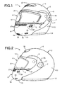
Fig. 1 is a perspective view of the entire portion
of a helmet in an ordinary worn state in the first
embodiment in which the present invention is applied to a
full-face-type helmet serving also as a jet-type helmet;
Fig. 2 is a right side view of the entire portion
of the helmet shown in Fig. 1 in an ordinary worn state;
Fig. 3 is a right side view of the entire portion
of the helmet shown in Fig. 1 with the subsidiary cap
portion raised;
Fig. 4 is a longitudinal sectional partial view,
taken along the center, of the helmet shown in Fig. 2,
which explains the subsidiary cap portion locking
mechanism and from which the backing member and rim member
for the subsidiary cap portion are omitted;
Fig. 5 is a view similar to Fig. 4, showing a
state the release button is depressed;
Fig. 6 is a view similar to Fig. 4, showing a
state wherein the subsidiary cap portion is slightly
raised from the state shown in Fig. 5;
Fig. 7 is a perspective view of the release button
and a holding mechanism for it shown in Fig. 4;
Fig. 8 is an exploded perspective view of the
release button and the holding mechanism for it shown in
Fig. 7;
Fig. 9 is a longitudinal sectional view, taken
along the center, of the release button and the holding
mechanism for it shown in Fig. 7;
Fig. 10 is a perspective view of the entire
portion of a helmet in an ordinary worn state in the
second embodiment in which the present invention is
applied to a full-face-type helmet serving also as a jet-type
helmet;
Fig. 11 is a right side view of the entire portion
of the helmet shown in Fig. 10 in an ordinary worn state;
Fig. 12 is a right side view of the entire portion
of the helmet shown in Fig. 10 with the subsidiary cap
portion raised;
Fig. 13 is a longitudinal sectional partial view,
taken along the center, of the helmet shown in Fig. 11,
which explains the subsidiary cap portion locking
mechanism and from which the backing member and rim member
for the subsidiary cap portion are omitted;
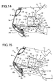
Fig. 14 is a view similar to Fig. 13, showing a
state wherein the release button is depressed;
Fig. 15 is a view similar to Fig. 13, showing a
state wherein the subsidiary cap portion is slightly
raised from the state shown in Fig. 14;
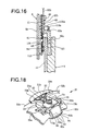
Fig. 16 is a sectional view taken along a line XVI
- XVI in Fig. 13;
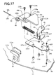
Fig. 17 is a perspective exploded view of the main
part of the right subsidiary cap portion locking mechanism
shown in Fig. 13;
Fig. 18 is a perspective view of the release
button and a holding mechanism for it shown in Fig. 13;
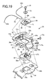
Fig. 19 is an exploded perspective view of the
release button and the holding mechanism for it shown in
Fig. 18;
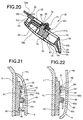
Fig. 20 is a longitudinal sectional view, taken
along the center, of the release button and the holding
mechanism for it shown in Fig. 18;
Fig. 21 is a sectional view taken along a line XXI
- XXI in Fig. 11; and
Fig. 22 is a sectional view taken along a line
XXII - XXII in Fig. 12.
Detailed Description of the Invention
The preferred embodiments in which the present
invention is applied to a full-face-type helmet serving
also as a jet-type helmet will be described with reference
to the accompanying drawings.
First Embodiment
The first embodiment in which the present
invention is applied to a full-face-type helmet serving
also as a jet-type helmet will be described first with
reference to Figs. 1 to 9.
As shown in Figs. 1 to 3, a full-face-type helmet
1 serving also as a jet-type helmet is made up of a full-`"
face-type cap-shaped head protecting body 2, a shield
plate 4, and a pair of right and left chin straps (not
shown). Note that the full-face-type cap-shaped head
protecting body 2 is to be worn on the head of a helmet
wearer, e.g., the rider of a motor cycle, and serves as a
jet-type head protecting body as well. The shield plate 4
can open/close a window opening 3 formed in the front
surface of the full-face-type head protecting body 2 to
oppose the portion between the forehead and chin of the
wearer (i.e., almost the central portion of the face). The
chin straps are attached to the inner surface portions of
the full-face-type head protecting body 2.
As is conventionally known, the head protecting
body 2 has a main cap portion 5 and a subsidiary cap
portion 6. The main cap portion 5 can have almost the same
shape as that of the cap portion of a jet-type helmet. The
subsidiary cap portion 6 is attached to the main cap
portion 5 on the right and left sides with a pair of right
and left attaching screws 7 serving as axial support
means, so as to be reciprocally pivotal. Accordingly, a
large window 8 is formed in the main cap portion 5 to be
defined by a large notch extending upward from the lower
end of the front surface of the main cap portion 5. As is
conventionally known, the subsidiary cap portion 6 has a
chin cover 6a and a pair of right and left ears 6b. The
chin cover 6a is arcuated to expand forward. The ears 6b
extend from the right and left ends of the chin cover 6a
and are axially supported on the right and left sides of
the main cap portion 5 with a pair of right and left
attaching screws 7 to be reciprocally movable. The
subsidiary cap portion 6 is formed with a large window 15
defined by a large notch extending downward from the upper
end of its front surface. When the subsidiary cap portion
6 pivots downward with respect to the main cap portion 5
to be located at the lower position (the state shown in
Figs. 1 and 2), it serves as a chin covering means for
covering the wearer's chin to close the lower portion of
the window 8. Hence, the upper portion of the window 8
defines the window opening 3. The window opening 3 is
formed of a region surrounded by the rim of the window 8
of the main cap portion 5 and the rim of the window 15 of
the subsidiary cap portion 6.
As is conventionally known, the shield plate 4 can
be made of a transparent or translucent hard material such
as polycarbonate or another type of hard synthetic resin.
The shield plate 4 is reciprocally pivotally attached to
the subsidiary cap portion 6 at the right and left sides
with a pair of right and left attaching screws 9 serving
as axial support means. When the subsidiary cap portion 6
is at the lower position to serve as the chin covering
means (the state shown in Figs. 1 and 2), the shield plate
4 closes the window opening 3 at the backward position
(i.e., the lower position); and opens the window opening 3
at the forward, position (i.e., the upper position).
As is conventionally known, the main cap portion 5
can be made up of a jet-type outer shell 11, a rim member
12 having a substantially U-shaped section, and a backing
member (not shown) for the main cap portion. The outer
shell 11 forms the outer wall of the main cap portion 5.
Note that the rim member 12 has a substantially E-shaped
section at the upper end portion of the window 8. The rim
member 12 has a substantially U-shaped section at the
reminding portion of the window 8 except the upper end
portion and is fixed to the outer shell 11 throughout the
end portion of the outer shell 11 with an adhesive or the
like. The backing member is brought into contact with the
outer shell 11 to be fixed to it in contact with the inner
surface of the outer shell 11 with an adhesive or the
like. As is conventionally known, the outer shell 11 can
be made of a composite material. More specifically, the
outer shell 11 can be formed by lining the inner surface
of a strong shell body made of a hard synthetic resin,
e.g., FRP, with a flexible sheet such as an unwoven
fabric. As is conventionally known, a portion of the rim
member 12 having the substantially U-shaped section can be
made of a soft synthetic resin such as foamed vinyl
chloride or synthetic rubber. A portion of the rim member
12 having the substantially E-shaped section can be made
of an elastic material with high flexibility such as
synthetic rubber.
As is conventionally known, the backing member for
the main cap portion can be constituted by an impact
absorbing liner for the main cap portion, attached to the
inner surface of the outer shell 11 for the main cap
portion with an adhesive or the like, and a blockish
inside pad for the main cap portion and a backing cover
for the main cap portion which are sequentially attached
to cover substantially the inner surface of the impact
absorbing liner. The impact absorbing liner for the main
cap portion can be made of a material with appropriate
rigidity and plasticity such as foamed polystyrene or
another synthetic resin. The blockish inside pad for the
main cap portion can be made of one or a plurality of
elastic materials with high flexibility such as urethane
foam or another synthetic resin, and a porous unwoven
fabric covering the inner and outer surfaces of the
elastic material(s) to form a bag. The backing cover for
the main cap portion can be made of a porous unwoven
fabric formed by laminating layers, consisting of an
elastic material with high flexibility such as urethane
foam or another synthetic resin, on the surface opposing
the impact absorbing liner for the main cap portion.
As is conventionally known, the subsidiary cap
portion 6 can be made up of an outer shell 14, a rim
member 16 having a substantially E-shaped section, and a
backing member (not shown) for the subsidiary cap portion.
The outer shell 14 forms the outer wall of the subsidiary
cap portion 6. The rim member 16 is fixed to part (i.e.,
the end portion of the window 15) of the end portion of
the outer shell 14 with an adhesive or the like. The
backing member for the subsidiary cap portion is brought
into contact with the outer shell 14 to be fixed to it in
contact with the inner surface of the outer shell 14 with
an adhesive or the like. As is conventionally known, the
outer shell 14 and the rim member 16 having the
substantially E-shaped section can be made of the same
materials as those described above concerning the outer
shell 11 for the main cap portion and the rim member 12
having substantially the E-shaped section. A pair of right
and left cover members 17 for externally covering the pair
of right and left attaching screws 7 are attached to the
outer shell 14 to be reciprocally pivotal about their
front edge portions as the fulcrums. When the cover
members 17 are outwardly pivoted forward through about
90°, the heads of the attaching screws 7 are exposed.
Inversely, when the cover members 17 are pivoted backward,
the heads of the attaching screws 7 are covered by the
cover members 17, as shown in Figs. 1 to 3.
As is conventionally known, the backing member for
the subsidiary cap portion can be constituted by an impact
absorbing liner for the subsidiary cap portion, and a
backing cover for the subsidiary cap portion, attached to
the inner surface of the impact absorbing liner to
substantially cover it. The impact absorbing liner for the
subsidiary cap portion is attached to the inner surface of
the outer shell 14 for the subsidiary cap portion with an
adhesive or the like, and can be made of a material with
appropriate rigidity and plasticity such as foamed
polyurethane rubber or another synthetic resin. The
backing cover for the subsidiary cap portion can be made
of synthetic leather or another cloth made of a synthetic
resin such as vinyl chloride resin, or another fabric.
A pair of right and left subsidiary cap portion
locking mechanisms 21 are incorporated in the head
protecting body 2. Each of the pair of subsidiary cap
portion locking mechanisms 21 has a function of locking
the subsidiary cap portion 6 at the lower position with
the head protecting body 2, as is dearly shown in Fig. 4.
The pair of subsidiary cap portion locking mechanisms 21
are unlocked by a common release button 22 serving as an
unlocking means or member.
As shown in Figs. 7 to 9, the release button 22 is
held by a button holding mechanism 20 serving as an
unlocking member holding mechanism at substantially the
central portion of the subsidiary cap portion 6 (i.e., a
portion opposing the distal end of the wearer's chin) to
be linearly, reciprocally slidable. The button holding
mechanism 20 is constituted by the outer shell 14 for the
subsidiary cap portion, and a button holding member 23.
The button holding member 23 is made of an appropriate
material such as a synthetic resin, e.g., polyacetal resin
or ABS resin. The button holding member 23 has a member
main body 25. The member main body 25 has an elongated
hole 24 extending at substantially the central portion of
its upper surface in the back-and-forth direction, and
forms a substantially box-like lid. A pair of left and
right substantially V-shaped attached pieces 26a and 26b
are formed on the left and right sides of the member main
body 25 by, e.g., monolithic molding. The attached pieces
26a and 26b respectively have screw engaging holes 27. A
guide 30 is formed near the front end of the upper surface
of the member main body 25 by, e.g., monolithic molding.
The guide 30 has a pair of left and right arcuated pieces
29a and 29b extending outwardly to the left and right,
respectively. A pair of left and right subsidiary guide
plates 31a and 31b are formed on the front end face of the
member main body 25 by, e.g., monolithic molding. A pair
of left and right attaching bosses 33a and 33b for
attaching the button holding member 23 are formed at
substantially the central portion of the outer shell 14
for the subsidiary cap portion (i.e., a portion opposing
the distal end of the wearer's chin) by, e.g., monolithic
molding. A finger-inserting aperture 34 is formed between
the pair of attaching bosses 33a and 33b.
As shown in Figs. 7 and 8, the release button 22
is formed of an appropriate material such as a synthetic
resin, e.g., nylon 6 or ABS resin, to have a substantially
blockish shape. A finger-inserting notched portion 28 is
formed in one half of the lower surface of the release
button 22. The notched portion 28 forms, in the release
button 22, a press surface 28a (i.e., a surface
substantially perpendicularly intersecting the aperture
34) used for pressing the release button 22 with a finger.
A columnar portion 35 having a screw hole 36 is formed on
substantially the central portion of the upper surface of
the release button 22 by, e.g., monolithic molding. A pair
of left and right substantially L-shaped arms 37a and 37b,
and a protrusion 38, all of which extend from the columnar
portion 35, are formed on the upper surface of the release
button 22 by, e.g., monolithic molding.
As shown in Figs. 7 and 8, a wire attaching member
39 serving as a wire body attaching member attached and
fixed to the release button 22 is formed of an appropriate
material such as a synthetic resin, e.g., nylon 6 or ABS
resin, to have a substantially platelike shape. An
elongated hole 40 extending in the back-and-forth
direction is formed at substantially the central portion
of the attaching member 39. A substantially semicircular
wire engaging portion 71 is formed on a surface of the
attaching member 39 opposite to the outer shell 14 by,
e.g., monolithic molding, to be near the rear end of the
elongated hole 40. A pair of left and right projecting
ridges 72a and 72b are formed on the left and right sides
of the wire engaging portion 71 by, e.g., monolithic
molding.
The release button 22 is accommodated in the
button holding mechanism 20, constituted by the outer
shell 14 for the subsidiary cap portion and the button
holding member 23, to be linearly reciprocally slidable.
To accommodate the release button 22, first, the release
button 22 is fitted in the button holding member 23 to be
linearly reciprocally slidable. When fitting the release
button 22, the columnar portion 35, the pair of left and
right arms 37a and 37b, and the protrusion 38 of the
release button 22 are inserted in the elongated hole 24 of
the button holding member 23. In this case, the pair of
arms 37a and 37b are held to be linearly reciprocally
slidable along the left and right rims of the elongated
hole 24. The right and left side surfaces and upper
surface of the release button 22 are also held to be
linearly reciprocally slidable along the left and right
inner surfaces and lower surface of the member main body
25 of the button holding member 23.
Subsequently, the button holding member 23 fitted
with the release button 22 is attached and fixed to the
outer shell 14 for the subsidiary cap portion. A pair of
left and right attaching screws 73a and 73b inserted in
the screw engaging holes 27 of the attached pieces 26a and
26b are screwed and fixed in the pair of left and right
attaching bosses 33a and 33b of the outer shell 14 for the
subsidiary cap portion, attaching and fixing the member
23. Accordingly, the release button 22 is reciprocally
slidable with respect to the button holding member 23 in
directions indicated by arrows A and B in Figs. 4 and 7.
The wire attaching member 39 is attached and fixed
to the release button 22. An attaching screw 75 is
inserted in a washer 74 and the elongated hole 40 of the
wire attaching member 39, and the attaching screw 75 is
then screwed and fixed in the screw hole 36 of the
columnar portion 35 of the release button 22, thereby
attaching and fixing the member 39. In this case, the
washer 74 is placed on the wire engaging portion 71 and
the pair of left and right projecting ridges 72a and 72b
of the wire attaching member 39. The wire attaching member
39 is placed on the pair of left and right arms 37a and
37b and the protrusion 38 of the release button 22.
When the attaching screw 75 is slightly screwed
into the screw hole 36, an intermediate portion (in this
case, substantially the central portion) 32c of a tractive
wire 32, serving as a tractive flexible wire and made of a
metal or the like, is hooked on the substantially arcuated
portion of the wire engaging portion 71 of the wire
attaching member 39 to form substantially a U-letter
shape, and thereafter the attaching screw 75 is screwed
into the screw hole 36 to fix the wire attaching member
39. In this case, before screwing and fixing, the wire
attaching member 39 is linearly moved back and forth by
utilizing the elongated hole 40, so that the attaching
position in the back-and-forth direction of the wire
attaching member 39 with respect to the release button 22
can be adjusted. This adjusts the tautness of the tractive
wire 32 to remove the unnecessary slack of the tractive
wire 32. The left and right portions of the tractive wire
32 that are directly continuous to the substantially U-shaped
intermediate portion 32c are wound on the pair of
left and right arcuated pieces 29a and 29b. The tractive
wire 32 is used commonly by the pair of right and left
subsidiary cap portion locking mechanisms 21. More
specifically, the tractive wire 32 has a pair of left and
right wire portions 32a and 32b continuous to the two ends
of the U-shaped intermediate portion 32c. The wire portion
32a (to be referred to as the "tractive wire 32a"
hereinafter) on the right side (i.e., on right side of the
front surface of the helmet 1; this applies to the
following description) is used by the right subsidiary cap
portion locking mechanism 21. The wire portion 32b (to be
referred to as the "tractive wire 32b" hereinafter) on the
left side (i.e., on left side of the front surface of the
helmet 1; this applies to the following description) is
used by the left subsidiary cap portion locking mechanism
21. Since the right and left subsidiary cap portion
locking mechanisms 21 are symmetric, a description will be
made concerning the right subsidiary cap portion locking
mechanism 21 hereinafter with reference to Figs. 4 to 6,
and a description on the left subsidiary cap portion
locking mechanism 21 will be omitted.
Referring to Figs. 4 to 6, an attaching base 41
made of an appropriate material such as a metal like
stainless steel, or a synthetic resin like ABS resin, is
attached and fixed to the inner surface of the right ear
6b of the subsidiary cap portion 6 with an attaching screw
42. A lock lever 43 serving as a movable locking means or
member is axially supported on the attaching base 41 with
an attaching screw 44 to be reciprocally pivotal. A
stopped portion 45 made of a flat-plate-like upright
portion is integrally formed on one end portion of the
lock lever 43. A wire attached portion 46 formed of an L-shaped
upright portion is integrally formed on the other
end portion of the lock lever 43. Since the stopped
portion 45 is inserted in an incision 47 formed in the
attaching base 41, the forward and backward pivot
positions of the lock lever 43 are regulated by the
attaching base 41. The wire attached portion 46 fixes the
distal end portion of an attaching rod 48, the proximal
end portion of which extends from the lock lever 43. The
free end portion of the tractive wire 32a is fixed to the
attaching rod 48.
A spring retainer 49 which can have a
substantially cup-like shape is formed on the attaching
base 41 by monolithic molding or with an adhesive. The
tractive wire 32a is inserted in a wire inserting hole 50
of the spring retainer 49. The tractive wire 32a extends
through a flexible tube 52 made of an appropriate elastic
material such as synthetic rubber. One end portion of the
tube 52 is held in position by the arcuated piece 29a and
subsidiary guide plate 31a of the button holding member
23, and abuts against a front end face 63 of the member
main body 25. The other end portion of the tube 52 abuts
against the spring retainer 49. One end portion of a tube
52 identical to the above tube 52 and used by the left
subsidiary cap portion locking mechanism 21 is also held
in position by the arcuated piece 29b and subsidiary guide
plate 31b of the button holding member 23, and abuts
against the front end face 63 of the member main body 25.
A compression coil spring 51 through which the
tractive wire 32a extends is interposed between the spring
retainer 49 and the wire attached portion 46 of the lock
lever 43. For this reason, the lock lever 43 is biased by
the coil spring 51 to pivot counterclockwise in Fig. 4
about the attaching screw 44 as the center. Since the lock
lever 43 is biased to pivot counterclockwise in Fig. 4,
the release button 22 is tractively biased by the tractive
wire 32a to move backward in the direction indicated by
the arrow B in Figs. 4 and 7.
The release button 22 can move forward in the
direction indicated by the arrow A in Figs. 4 and 7
against the tractive biasing force of the tractive wire
32a. The forward moving direction A of the release button
22 forms an acute angle with respect to a downward
moving direction (i.e., a backward pivot direction about
the attaching screws 7 as the fulcrum) C of the subsidiary
cap portion 6, as shown in Fig. 4. In the embodiment shown
in Fig. 4, the acute angle is about 25°. However, from
the viewpoint of practicability, this angle is preferably
0° to 60°, and more preferably 0° to 45°. The forward
moving direction A of the release button 22 is inward
(i.e., backward in Fig. 4) of the downward moving
direction C of the subsidiary cap portion 6. However, this
direction A need not be inward but can be outward. In
order to operate the release button 22 forward and move
the subsidiary cap portion 6 upward very smoothly, the
forward moving direction A of the release button 22 is
preferably inward of the downward moving direction C of
the subsidiary cap portion 6. In this case, the acute
angle is particularly preferably 5° to 45°.
A pair of right and left lock pins 54 serving as a
stationary locking means or member project near the lower
end of the outer surface of the outer shell 11 of the main
cap portion 5. The lock levers 43 of the right and left
subsidiary cap portion locking mechanisms 21 selectively
engage with the lock pins 54 depending on their pivot
positions. Each lock lever 43 is formed with an abutting
portion 43a against which the corresponding lock pin 54
abuts. A locking recess 62 to engage with the lock pin 54
is formed adjacent to the abutting portion 43a.
The respective portions (i.e., the attaching bases
41, coil springs 51, lock levers 43, attaching rods 48,
attaching screws 42 and 44, and the like) of the locking
mechanisms 21, the release button 22, the button holding
mechanism 20 (i.e., the button holding member 23,
attaching bosses 33a and 33b, and the like), the wire
attaching member 39, the washer 74, the attaching screws
73a, 73b, and 75, the tubes 52, the tractive wires 32a and
32b, and the like are arranged along the inner surface of
the outer shell 14 for the subsidiary cap portion. Hence,
recesses and ridge grooves for accommodating these
portions are formed in the surface of the impact absorbing
liner for the subsidiary cap portion that opposes the
outer shell 14.
As shown in Figs. 1 to 3, a ventilation aperture
forming member 55 for the forehead is attached to the
outer surface of the forehead portion of the main cap
portion 5. A stopper 56 for regulating the backward
position of the shield plate 4 is provided to the right
portion of the outer surface of the subsidiary cap portion
6. Various types of ventilation apertures 57, 58, and 59
are formed in the chin cover 6a of the subsidiary cap
portion 6. As shown in Figs. 4 to 6, an air guide plate 60
is attached to the inner surface of the chin cover 6a with
attaching screws 61 so as to oppose the ventilation
apertures 57. Therefore, air flowing into the head
protecting body 2 through the ventilation apertures 57 is
guided by the front surface of the air guide plate 60 to
move upward in the head protecting body 2 along the inner
surface of the shield plate 4.
How to use the full-face-type helmet serving also
as the jet-type helmet having the above arrangement will
be described.
Assume that the wearer wishes to use the helmet 1
as a full-face-type helmet. If the subsidiary cap portion
6 is at the upper position, as shown in Fig. 3, the wearer
pivots it downward about the attaching screws 7 as the
center, thereby bringing it to the lower position shown in
Figs. 1 and 2.
In this case, the abutting portions 43a of the
lock levers 43 provided to the subsidiary cap portion 6 as
shown in Fig. 6 abut against the lock pins 54. The lock
levers 43 are accordingly pressed by the lock pins 54, and
pivot slightly forward clockwise in Fig. 6 about the
attaching screws 44 as the fulcrum against the biasing
force of the coil springs 51. The lock pins 54 thus ride
over the abutting portions 43a of the lock levers 43, as
shown in Fig. 4, to engage with the corresponding locking
recesses 62. The subsidiary cap portion 6 is securely
locked by the main cap portion 5 with the pair of right
and left subsidiary cap portion locking mechanisms 21, so
that the head protecting body 2 serves as the full-face-type.
Assume that the wearer wishes to use the helmet 1
shown in Figs. 1 and 2, currently serving as the full-face-type
helmet, as a jet-type helmet shown in Fig. 3. In
the state shown in Fig. 4, the wearer inserts his finger
(e.g., index finger and/or middle finger) in the notched
portion 28 of the release button 22 through the aperture
34 located at substantially the central portion of the
outer surface of the chin cover 6a of the subsidiary cap
portion 6. The wearer presses the press surface 28a of the
release button 22 with this finger downward in the forward
direction, indicated by the arrow A in Fig. 4, against the
biasing force of the coil springs 51. In this case, since
the press surface 28a substantially perpendicularly
intersects the forward direction A of the release button
22, the direction of the force applied by the finger onto
the release button 22 substantially coincides with this
forward direction A.
Since the release button 22 moves forward in the
direction indicated by the arrow A against the biasing
force of the coil springs 51, the tractive wire 32a is
pulled by the release button 22 to slide along the
arcuated piece 29a of the button holding member 23.
Therefore, the lock levers 43 in the state shown in Fig. 4
pivot forward clockwise about the attaching screws 44 as
the fulcrum to be set in the state shown in Fig. 5. This
unlocks the subsidiary cap portion 6 locked on the main
cap portion 5 by the subsidiary cap portion locking
mechanisms 21. Accordingly, if the wearer simultaneously
places his finger (e.g., the thumb) on substantially the
central portion of the lower end of the subsidiary cap
portion 6 (e.g., grabs the subsidiary cap portion 6 from
the upper and lower sides with his index finger and/or
middle finger inserted in the notched portion 28 and his
thumb placed on substantially the central portion of the
lower end of the subsidiary cap portion 6), and raises the
subsidiary cap portion 6, the subsidiary cap portion 6
pivots upward about the attaching screws 7 as the fulcrum.
The subsidiary cap portion 6 is set in the state shown in
Fig. 3 through the state shown in Fig. 6. Thus, the head
protecting body 2 serves as the jet-type.
In the first embodiment, the tractive wires 32a
and 32b are inserted in the tubes 52. The tractive wires
32a and 32b can be easily set not to come into substantial
contact with any foreign matter other than the tubes 52.
As a result, the tractive wires 32a and 32b can always
move comparatively smoothly. These tubes 52 can be omitted
if necessary. If the tubes 52 are omitted, the tractive
wires 32a and 32b are preferably selected to have such a
length that they extend substantially linearly between the
arcuated pieces 29a and 29b of the guide plate 30 of the
button holding member 23 and the spring retainers 49 of
the attaching bases 41.
Second Embodiment
The second embodiment in which the present
invention is applied to a full-face-type helmet serving
also as a jet-type helmet will be described with reference
to Figs. 10 to 22.
The helmet of the second embodiment shown in Figs.
10 to 22 has substantially the same arrangement, function,
and effect as those of the helmet according to the first
embodiment described above shown in Figs. 1 to 9, except
for the differences and respects concerning them described
in the following items (1) to (7). Accordingly, in the
following description, only the differences and respects
concerning them described in these items (1) to (7) will
be described. Portions that are common between the helmet
according to the second embodiment shown in Figs. 10 and
22 and the helmet according to the first embodiment
described above shown in Figs. 1 to 9 are denoted by the
same reference numerals, and a description other than the
differences and respects concerning them will be omitted.
Items (1) and (2)
Each of the pair of right and left support plates
81 is an elongated platelike member extending in
substantially the back-and-forth direction, as shown in
Figs. 11 and 12, and can be made of a material similar to
that described above concerning the button holding member
23. The support plates 81 are fixed to an outer shell 11
for a main cap portion with attaching screws 84 at their
portions near the front end portions. The portions of the
support plates 81 near the rear end portions are also
fixed, together with ears 6b of the subsidiary cap portion
6, to the outer shell 11 for the main cap portion with
attaching screws (i.e., axial support means) 7. The cover
members 17 provided in the first embodiment for the
attaching screws 7 are omitted in the second embodiment.
As shown in Figs. 21 and 22, a projection 86 to
fit in a coil portion 85a provided at the central portion
of a spring 85 serving as a biasing means is formed on
each support plate 81 by monolithic molding or the like.
The spring 85 serves as a torsion coil spring, and further
has first and second wire portions 85b and 85c extending
from the coil portion 85a in substantially the opposite
directions. The support plate 81 is formed with a pair of
spring catching projections 87 and 88 by monolithic
molding or the like to engage with the first coil portion
85b. The first wire portion 85b is inserted between the
pair of projections 87 and 88.
As shown in Figs. 21 and 22, a pair of right and
left projections 89 serving as positioning means project
from the inner surface of an outer shell 14 at each of the
pair of right and left ears 6b of the subsidiary cap
portion 6. The second wire portion 85c of the spring 85 is
bent almost arcuatedly. When the subsidiary cap portion 6
is at the lower position, as shown in Figs. 11 and 21, the
positioning projection 89 serving also as the spring hook
means presses against the arcuated second wire portion
85c.
The support plates 81 are formed with a pair of
right and left recesses 90 serving as positioning means.
When the subsidiary cap portion 6 is at the lower
position, as shown in Fig. 11, the positioning projections
89 lightly engage or fit with the recesses 90, as shown in
Fig. 21, to prohibit the subsidiary cap portion 6 from
moving with a comparatively small action force. When the
projections 89 engage or fit with the recesses 90, the
upward biasing force for the subsidiary cap portion 6
generated by the springs 85 can be entirely or partially
reduced by this engagement or fitting. The subsidiary cap
portion 6 located at the lower position is not only locked
at the lower position by the pair of right and left
subsidiary cap portion locking mechanisms 21, but is
lightly held in position at the lower position by the
recess-projection engagement of the positioning means 89
and 90, 50 that its forward movement is prohibited by a
comparatively small action force. The springs 85 bias the
subsidiary cap portion 6 upward (i.e., in the forward
direction) through the positioning projections 89, so that
the subsidiary cap portion 6 is raised smoothly when the
recess-projection engagement is canceled. Furthermore,
since the springs 85 bias the subsidiary cap portion 6
clockwise in Figs. 11 and 13 with respect to the main cap
portion 5 about the attaching screws (i.e., axial support
means) 7 as the fulcrum, they prevent lock pins 54 from
removing accidentally from locking recesses 62 of lock
levers 43 upon vibration or the like of the helmet 1.
Each support plate 81 is formed with a
substantially semicylindrical stopper projection 91 by
monolithic molding or the like. When the subsidiary cap
portion 6 is at the upper position, as shown in Fig. 12,
the positioning projection 89 engages with the stopper
projection 91, as shown in Fig. 22. The support plate 81
is also formed with a stopper projection 92, having an
inclined surface, adjacent to the stopper projection 91 by
monolithic molding or the like. While the subsidiary cap
portion 6 moves from the lower position to immediately
before the upper position, the positioning projection 89
gradually rides over the inclined surface of the stopper
projection 92. Accordingly, while the subsidiary cap
portion 6 moves from the lower position to immediately
before the upper position, the positioning projection 89
rides over the inclined surface of the stopper projection
92 and thereafter passes it. As a result, as shown in Fig.
22, the positioning projection 89 (and also the subsidiary
cap portion 6) is completely prohibited by the stopper
projection 91 from moving further forward and by the
stopper projection 92 from moving backward, with a
comparatively small action force.
Item (3)
The finger putting plate 83 having a substantially
vertical finger putting surface 83a is formed on the rear
end face of a member main body 25 of the button holding
member 23 of the button holding mechanism 20 by monolithic
molding or the like. The finger putting surface 83a has
projecting ridges 93a, 93b, and 94 at its left and right
side end portions and lower end portion, respectively. The
projecting ridges 93a, 93b, and 94 form a substantially
U-letter shape as a whole. Accordingly, when raising the
subsidiary cap portion 6, if the wearer places his finger
(e.g., thumb) on the finger putting surface 83a of the
finger putting plate 83, in place of placing his finger at
substantially the central portion of the lower end of the
subsidiary cap portion 6 as in the first embodiment, and
thereafter raises the subsidiary cap portion 6 upward,
this raising operation can be performed smoothly.
The outer shell 14 is formed with an expansion 95
at substantially the central portion of the lower end of
the chin cover 6a of the subsidiary cap portion 6 to
slightly expand forward to conform to the shape of the
finger putting plate 83.
Item (4)
In the second embodiment, the attaching base 41
corresponding to the attaching base 41 of the first
embodiment is constituted by the main attaching base 41
and the subsidiary attaching base 82, as shown in Figs. 13
and 17. In this case, the subsidiary attaching base 82 may
be made of the same material as that described above
concerning the attaching base 41. Note that the main
attaching base 41 is preferably made of a metal and the
subsidiary attaching base 82 is preferably made of a
synthetic resin.
As shown in Fig. 17, the main attaching base 41
can have a flat platelike shape. The main attaching base
41 is formed with a pair of boss inserting holes 101a and
bib, a rivet inserting hole 102, a boss inserting hole
103, and a screw inserting hole 104. In the first
embodiment, the spring retainer 49 is formed on the
attaching base 41. In the second embodiment, a spring
retainer 49 is formed on the subsidiary attaching base 82
by monolithic molding or the like. The subsidiary
attaching base 82 has a step 82a at substantially its
central portion, and a front plate 82b and a rear plate
82c on the two sides of the step 82a. The rear plate 82c
is formed with a pair of screw inserting bosses 105a and
105b and the spring retainer 49 by monolithic molding or
the like.
Spherical bodies 106 made of a metal or the like
are fixed to the free ends of the pair of right and left
tractive wires 32a and 32b, as shown in Figs. 13 and 17. A
substantially semicircular engaging notch 107 is formed on
the free end of a wire attached portion 46 of each lock
lever 43. A substantially circular engaging aperture 108
is formed in a lever main body 109 of the lock lever 43,
on a side of the engaging notch 107 opposite to the outer
shell 14.Portions near the free ends of the tractive wires
32a and 32b are inserted between the lever main bodies 109
of the lock levers 43 and the wire attached portions 46
from above, and the spherical bodies 106 are fitted in the
engaging notches 107 and engaging apertures 108, thereby
fixing the free ends of the tractive wires 32a and 32b to
the lock levers 43.
On the inner surface of the outer shell 14, a pair
of upper and lower projecting ridges 111a and 111b
extending substantially horizontally are formed on each of
the left and right sides of the chin cover 6a of the
subsidiary cap portion 6, as shown in Figs. 13 and 17, by
monolithic molding or the like. On the inner surface of
the outer shell 14, a pair of upper and lower screwing
bosses 112a and 112b, a positioning boss 113, and a
screwing boss 114 are formed on each of the left and right
sides of the chin cover 6a of the subsidiary cap portion 6
by monolithic molding or the like, to be adjacent to the
projecting ridges 111a and 111b. The substantially
intermediate portion of each of the tractive wires 32a and
32b is interposed between the corresponding pair of
projecting ridges 111a and 111b so that it is positioned
to a certain degree. A rivet 116 inserted in a rivet
engaging hole 115, formed in the lever main body 109 of
the lock lever 43, and the rivet engaging hole 102 in the
main attaching base 41 pivotally fixes the lock lever 43
to the attaching base 41. The positioning boss 113 is
fitted in the boss inserting hole 103 of the attaching
base 41, and the front surface of the attaching base 41 is
abutted against the distal end face of the screwing boss
114. After that, a screw 117 is inserted in the screw
inserting hole 104 of the attaching base 41 and screwed
into the screwing boss 114, thereby fixing the attaching
base 41 to the inner surface of the outer shell 14.
As shown in Figs. 13 and 17, the pair of screwing
bosses 112a and 112b are inserted in the boss inserting
holes 101a and 101b of the attaching base 41. The distal
end faces of the bosses 112a and 112b abut against a
surface, on the outer shell 14 side, of the front plate
82b of the subsidiary attaching base 82. A pair of upper
and lower screws 118a and 118b are inserted in the screw
inserting bosses 105a and 105b, and screwed into the
screwing bosses 112a and 112b, thereby fixing the
subsidiary attaching base 82 and main attaching base 41 to
the inner surface of the outer shell 14.
According to the above arrangement, as shown in
Fig. 16, a gap 121 is defined by the main attaching base
41, the lock lever 43, and the rear plate 82c of the
subsidiary attaching base 82. Accordingly, the subsidiary
attaching base 82 serves as a gap defining member as well.
When the subsidiary cap portion 6 is at the lower position
shown in Figs. 13 and 14 and at the intermediate position
shown in Fig. 15 which is slightly above the lower
position, portions of the outer shell 11 of the main cap
portion 5 near its lower end are inserted in the
corresponding gaps 121. Therefore, portions of the outer
shell 11 near its lower end (also the lock pins 54) and
the lock levers 43 of the subsidiary cap portion 6 are
positioned relative to each other to a certain degree in
the direction of thickness of the outer shell 11. This can
prevent the lock pins 54 from accidentally, relatively
removing from the locking recesses 62 of the lock levers
43, or from abutting portions 43a of the lock levers 43,
to a certain degree. A cover member (not shown) for
covering the outer surface and, if necessary, the inner
surface as well, of a portion of the outer shell 11 near
its lower end may be provided, and the lock pins 54 may be
fixed to the cover member. This cover member can be made
of the same material as that described above concerning
the button holding member 23.
As shown in Fig. 16, on the inner surface of the
outer shell 14, the pair of right and left subsidiary
attaching bases 82 are formed on the right and left sides
of the chin cover 6a of the subsidiary cap portion 6.
Accordingly, the gap 121 is formed on each of the right
and left sides to form a pair. A pair of right and left
portions of the outer shell 11, near the lower end, of the
main cap portion 5 are inserted in the pair of right and
left gaps 121, respectively. This insertion amount is the
maximum when the subsidiary cap portion 6 is at the lower
position shown in Figs. 13 and 14, and decreases gradually
as the subsidiary cap portion 6 moves forward from the
lower position shown in Figs. 13 and 14 to the
intermediate position shown in Fig. 15 which is slightly
above the lower position. When the subsidiary cap portion
6 further moves upward from the intermediate position
shown in Fig. 15, the pair of right and left portions of
the outer shell 11 near its lower end completely disengage
from the pair of right and left gaps 121. When the
subsidiary cap portion 6 moves downward, an operation
precisely opposite to that described above is performed.
Item (5)
In the first embodiment, the pair of left and
right tubes 52 are provided to extend the pair of left and
right tractive wires 32a and 32b therethrough. In the
second embodiment, such tubes 52 are omitted. Therefore,
the tractive wires 32a and 32b extend substantially
linearly between arcuated pieces 29a and 29b of a guide 30
of the button holding member 23 and the spring retainers
49 of the subsidiary attaching bases 41.
Item (6)
In the second embodiment, the wire attaching
member 39 of the button holding mechanism 20 is arranged
upside down from the state of the first embodiment, as
shown in Figs. 18 and 19. Accordingly, a wire engaging
portion 71 and a pair of left and right projecting ridges
72a and 72b are formed on the surface of the wire
attaching member 39 on the outer shell 14 side.
In the post-assembly state shown in Figs. 18 and
20, a pair of left and right arms 37a and 37b of a release
button (i.e., unlocking member) 22 are fitted between the
pair of left and right projecting ridges 72a and 72b of
the wire attaching member 39. In other words, a projection
formed by the pair of left and right arms 37a and 37b (the
intermediate portion of this projection, i.e., the portion
between the pair of arms 37a and 37b, forms a notch) is
fitted in a recess formed between the pair of left and
right projecting ridges 72a and 72b through recess-projection
fitting, to be linearly, reciprocally slidable.
The wire engaging portion 71 of the wire attaching
member 39 is inserted between the pair of left and right
arms 37a and 37b. A U-shaped intermediate portion 32c of
the tractive wire 32 is hooked on the wire engaging
portion 71, and abuts against the right and left sides of
a columnar portion 35 of the release button 22.
Accordingly, the intermediate portion 32c is securely
sandwiched from the two sides by the proximal end portions
of the pair of left and right arms 37a and 37b of the
release button 22 and a surface of the wire attaching
member 39 on the outer shell 14 side.
In the first embodiment, the pair of arms 37a and
37b of the release button 22 linearly, reciprocally slide
along the rim of the elongated hole 24 of the button
holding member 23. In contrast to this, in the second
embodiment, the pair of projecting ridges 72a and 72b of
the wire attaching member 39 linearly, reciprocally slide
along the rim of an elongated hole 24 corresponding to
their counterpart of the first embodiment.
Item (7)
In the first embodiment, the chin cover 6a of the
subsidiary cap portion 6 is formed with the pair of right
and left comparatively large ventilation apertures 59. In
contrast to this, in the second embodiment, the right and
left ventilation aperture pairs 59, each consisting of
comparatively small two, front and rear ventilation
apertures, are formed.
Having described two specific preferred
embodiments of this invention with reference to the
accompanying drawings, it is to be understood that the
invention is not limited to that precise embodiments, and
that various changes and modifications may be effected
therein by one skilled in the art without departing from
the scope or spirit of the invention as defined in the
appended claims.
For example, in the first and second embodiments,
the direction perpendicularly intersecting the press
surface 28a of the release button 22 substantially
coincides with the forward moving direction A of the
release button 22. However, if these two directions more
or less do not coincide with each other, no problem
arises. In this case as well, an acute angle ' formed by
the direction perpendicularly intersecting the press
surface 28a of the release button 22 with respect to the
downward moving direction C of the subsidiary cap portion
6 may have the same angular range as that described
concerning the acute angle .