JP4428754B2 - helmet - Google Patents
helmet Download PDFInfo
- Publication number
- JP4428754B2 JP4428754B2 JP12450299A JP12450299A JP4428754B2 JP 4428754 B2 JP4428754 B2 JP 4428754B2 JP 12450299 A JP12450299 A JP 12450299A JP 12450299 A JP12450299 A JP 12450299A JP 4428754 B2 JP4428754 B2 JP 4428754B2
- Authority
- JP
- Japan
- Prior art keywords
- cap body
- auxiliary cap
- helmet
- auxiliary
- operation member
- Prior art date
- Legal status (The legal status is an assumption and is not a legal conclusion. Google has not performed a legal analysis and makes no representation as to the accuracy of the status listed.)
- Expired - Fee Related
Links
Images


Classifications
-
- A—HUMAN NECESSITIES
- A42—HEADWEAR
- A42B—HATS; HEAD COVERINGS
- A42B3/00—Helmets; Helmet covers ; Other protective head coverings
- A42B3/32—Collapsible helmets; Helmets made of separable parts ; Helmets with movable parts, e.g. adjustable
- A42B3/326—Helmets with movable or separable chin or jaw guard
Description
【0001】
【発明の属する技術分野】
本発明は、自動二輪車のライダなどのヘルメット使用者が頭部の保護などのために頭部に装着する頭部保護体(本文においては、単に「帽体」という)を備え、この帽体が、キャップ状の主帽体と、ヘルメット使用者の顎部を選択的に覆い得るように、この主帽体に昇降可能に取付けられた補助帽体とを有するヘルメットに関するものである。
【0002】
【従来の技術】
自動二輪車のライダなどが使用する乗車用ヘルメットとして、従来から、ヘルメット使用者の顎部を覆う顎覆い部が帽体に一体的に形成されているフルフェイス型と、ヘルメット使用者の顔面のほぼ全体を露出させることができるように、顎覆い部が帽体に形成されていないジェット型とが、それぞれ知られている。また、フルフェイス型ヘルメットとジェット型ヘルメットとの両者の機能を兼ね備えさせるために、ジェット型ヘルメットの帽体とほぼ同一の形状を有する主帽体と、ヘルメット使用者の顎部を選択的に覆い得るように、この主帽体に昇降回動可能に取り付けられた補助帽体とから帽体を構成したフルフェイス型ヘルメット(以下、「ジェット型兼用のフルフェイス型ヘルメット」という)も、従来から知られている。
【0003】
このような従来のジェット型兼用のフルフェイス型ヘルメットにおいては、補助帽体が下降位置にあるときには、この補助帽体が顎覆い手段として機能し、また、この補助帽体が上昇位置にあるときには、主帽体に設けられている大きい窓部全体が開放されるので、ジェット型ヘルメットの場合と同様に帽体が顎覆い手段を有さない状態となる。そして、このようなジェット型兼用のフルフェイス型ヘルメットを装着した使用者が自動二輪車を高速度で運転しているときには、ヘルメットは、使用者の顎部の周囲に大きな風圧が加わるのを防止するために、補助帽体を下降位置まで降した状態で使用される。また、ヘルメットには、このような高速運転時に補助帽体が大きな衝撃や大きな風圧などにより独りでに上昇しないように、補助帽体を主帽体に対してその下降位置にロックする補助帽体ロック機構が設けられている。
【0004】
このようなロック機構は、補助帽体の下降位置でのロックを解除し得るように、ロック解除操作手段またはロック解除操作部材としてのリリース・ボタンを備えている。そして、このリリース・ボタンをロック解除のために押圧操作したときには、補助帽体を下降位置から上昇位置へ向かわせる力が独りでに補助帽体に加わるようになっている。換言すれば、リリース・ボタンを上方へ押圧操作したときに、補助帽体の下降位置でのロックが解除されるようになっている。このために、補助帽体のロック解除のためにリリース・ボタンを上方へ押圧操作したときに、ロック機構による補助帽体のロックが解除されるとともに、リリース・ボタンを引き続き押圧操作するだけで、補助帽体を下降位置から上昇位置へと移動させ始めることができる。したがって、使用者は、リリース・ボタンを押圧操作するだけで、補助帽体のロック解除とこのロック解除された補助帽体の上昇動作とを連続的に素早く行うことができる。
【0005】
【発明が解決しようとする課題】
しかし、上述のような従来のジェット型兼用のフルフェイス型ヘルメットにおいては、使用者が自動二輪車を高速度で運転しているときに、例えば、シールド板(このシールド板はヘルメットの帽体の前面に形成されている窓孔を開閉し得るように補助帽体に取付けられている)を上方へ少し押し上げてこのシールド板により閉塞されている窓孔を少し開放しようとして、リリース・ボタンを誤って上方へ押圧操作したり、あるいはまた、リリース・ボタンに異物が下方から不測に当接したりすれば、補助帽体の下降位置でのロックが解除されるとともに補助帽体が下降位置から或る程度上昇してしまう。このために、使用者の顎部に大きな風圧が直接加わるおそれがあるので、使用者による自動二輪車の運転に不都合が生じる可能性がある。
【0006】
また、上述のような従来のジェット型兼用のフルフェイス型ヘルメットにおいては、ロック機構による補助帽体のロックを解除するための機構が複雑な構造であり、また、上記ロック解除の動作およびその逆のロック動作が迅速かつ円滑に行われにくいおそれがある。
【0007】
本発明は、従来のジェット型兼用のフルフェイス型ヘルメットの上述のような欠点をきわめて簡単な構成によりきわめて効果的に是正し得るようにしたものである。
【0008】
【課題を解決するための手段】
本発明は、ヘルメット使用者の頭部に装着する帽体が、キャップ状の主帽体と、ヘルメット使用者の顎部を選択的に覆い得るように、この主帽体に昇降可能に取付けられた補助帽体とを有し、上記補助帽体が上記顎部を覆う下降位置にあるときにこの補助帽体の左側および右側を上記主帽体に対してそれぞれロックする第1および第2のロック機構が、上記帽体に設けられ、上記第1および第2のロック機構による上記補助帽体の上記ロックを共通に解除するために往動操作される共通のロック解除操作部材が、上記補助帽体に設けられているヘルメットにおいて、上記ロック解除操作部材の往動操作を上記第1および第2のロック機構の第1および第2の可動側ロック部材に共通に伝達する共通の牽引用可撓性線条体を備え、上記線条体の一端部が上記第1の可動側ロック部材に結合されるとともに、上記線条体の他端部が上記第2の可動側ロック部材に結合され、上記ロック解除操作部材に線条体係止部が設けられ、上記線条体の中間部分が上記線条体係止部に係止されているヘルメットに係るものである。そして、本発明においては、その第1の観点によれば、上記線条体係止部が、上記ロック解除操作部材に取付けられた線条体取付け部材にほぼ半円形状に形成され、上記線条体の中間部分が、このほぼ半円形状の線条体係止部のほぼ円弧状の部分にほぼU字状に引っ掛けられて係止されていることができる。また、本発明においては、その第2の観点によれば、上記線状体取付け部材を上記ロック解除操作部材に対して摺動させることにより上記ロック解除操作部材に対する上記線条体取付け部材の取付け位置を調整して上記線条体のたるみを除去し得るように、上記線条体取付け部材が上記ロック解除操作部材に取付けられていることができる。
【0009】
さらに、本発明においては、その第3の観点によれば、上記ロック解除操作部材を往復動可能に保持するための操作部材保持機構が設けられ、この操作部材保持機構が、上記ロック解除操作部材を保持し得る保持部材を備え、この保持部材が、上記ロック解除操作部材を往動操作するときに指を当てることができる指当て面を有していることができる。そして、本発明においては、その第4の観点によれば、上記補助帽体の左側および右側に第1および第2の間隙形成部材が設けられ、上記補助帽体が少なくとも上記下降位置にあるときには、上記補助帽体の左側および右側と上記第1および第2の間隙形成部材との間に形成された第1および第2の間隙に上記主帽体の左側および右側の下端附近がそれぞれ挿入されるように構成することができる。また、本発明においては、その第5の観点によれば、上記第1および第2のロック機構におけるロックが不必要に解除されるのを防止するために、上記下降位置にある上記補助帽体を上記主帽体に対して上昇方向に付勢する付勢手段が設けられていることができる。さらに、本発明においては、その第6の観点によれば、上記ロック解除操作部材の往動方向が、上記補助帽体の上記下降方向に対して鋭角をなすように構成することができる。そして、本発明の上記第6の観点においては、上記ロック解除操作部材の上記往動方向が、上記補助帽体の上記下降方向よりも内側に向いており、上記鋭角が、5°〜45°であることができる。また、本発明の上記第6の観点においては、上記補助帽体が、軸支手段により上記主帽体に対して昇降回動可能に上記主帽体に取付けられていることができる。さらに、本発明の上記第6の観点においては、上記補助帽体が上記下降位置にあるときに上記主帽体に対する上記補助帽体の移動を比較的小さな作用力で阻止する位置決め機構が、上記ロック機構とは別に設けられ、上記位置決め機構が、上記主帽体に設けられた第1の位置決め手段と、上記補助帽体に設けられ上記第1の位置決め手段と凹凸嵌合する第2の位置決め手段とからなり、上記補助帽体が上記下降位置にあるときに、上記補助帽体を上記主帽体に対して上昇方向に付勢する付勢手段がさらに設けられ、この付勢手段の付勢力が、それ自体では、上記位置決め機構の凹凸嵌合を解除し得ない大きさに選定されていることができる。
【0010】
【発明の実施の形態】
つぎに、本発明をジェット型兼用のフルフェイス型ヘルメットに適用した実施例を図面を参照して説明する。
【0011】
第1の実施例
まず、本発明をジェット型兼用のフルフェイス型ヘルメットに適用した第1の実施例を図1〜図9を参照して説明する。
【0012】
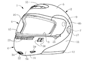
ジェット型兼用のフルフェイス型ヘルメット1は、図1〜図3に示すように、自動二輪車のライダなどのヘルメット使用者の頭部に装着されるジェット型兼用のフルフェイス型帽体2と、使用者の額部と顎部との間(すなわち、顔面のほぼ中央部分)に対向するように、帽体2の前面に形成された窓孔3を開閉し得るシールド板4と、帽体2の内側にそれぞれ取り付けられた左右一対の顎掛け用バンド(図示せず)とからなっている。
【0013】
帽体2は、従来から周知のように、ジェット型ヘルメットの帽体とほぼ同一の形状を有していてよい主帽体5と、この主帽体5の左右両側において軸支手段としての左右一対の取付けねじ7により主帽体5に往復回動可能に取付けられた補助帽体6とを有している。したがって、主帽体5には、前面下端から上方へ大きく切れ込んだ切り込みにより構成された大きい窓部8が形成されている。また、補助帽体6は、従来から周知のように、前方へ膨らむように弯曲した顎覆い部6aと、この顎覆い部6aの左右両端から上方に延びていて主帽体2の左右両側に左右一対の取付けねじ7によりそれぞれ往復回動可能に軸支された左右一対の耳部6bとを備えている。さらに、この補助帽体6には、前面上端から下方へ大きく切れ込んだ切り込みにより構成された大きい窓部15が形成されている。そして、補助帽体6が主帽体5に対して下方に回動した下降位置(図1および図2の状態)にあるときには、この補助帽体6は使用者の顎部を覆う顎覆い手段として機能して窓部8の下方部分を塞ぐので、この窓部8の上方部分により前記窓孔3が形成される。したがって、この窓孔3は、主帽体2の窓部8の縁部と補助帽体6の窓部15の縁部とによって囲まれた領域からなっている。
【0014】
シールド板4は、従来から周知のように、ポリカーボネート、その他の硬質合成樹脂などの透明または半透明な硬質材料からなっていてよく、補助帽体6の左右両側において軸支手段としての左右一対の取付けねじ9により補助帽体6に往復回動可能に取付けられている。そして、このシールド板4は、補助帽体6が下降位置に有って顎覆い手段として機能しているとき(図1および図2の状態)には、その復動位置(下降位置)において窓孔3を閉塞し、また、その往動位置(上昇位置)において窓孔3を開放する。
【0015】
主帽体5は、従来から周知のように、この主帽体5の外周壁を構成しているジェット型の外側シェル11と、この外側シェル11の端部の全周囲にわたって接着などにより取付けられた断面ほぼU字状(ただし、窓部8の上端部はほぼE字状)などの縁部材12と、外側シェル11の内周面に当接させて接着などにより取付けられた主帽体用裏当て部材(図示せず)とからなっていてよい。なお、外側シェル11は、従来から周知のように、FRP、その他の硬質合成樹脂などから成る強度の大きいシェル本体の内周面に不織布などの柔軟性シートを裏張りした複合材料からなっていてよい。また、断面ほぼU字状の縁部材12は、従来からの周知のように、発泡塩化ビニール、合成ゴム、その他の軟質合成樹脂などからなっていてよい。さらに、断面ほぼE字状の縁部材12は、従来から周知のように、合成ゴム、その他の可撓性に富んだ弾性材料からなっていてよい。
【0016】
上記主帽体用裏当て部材は、従来から周知のように、主帽体用外側シェル11の内周面に接着などにより取り付けられた主帽体用衝撃吸収ライナと、この衝撃吸収ライナの内周面をほぼ覆うように順次取り付けられた主帽体用ブロック状内装パッドおよび主帽体用裏当てカバーとからなっていてよい。そして、上記主帽体用衝撃吸収ライナは、従来から周知のように、発泡ポリスチレン、その他の合成樹脂などの適度な剛性と適度な塑性とを備えた材料からなっていてよい。また、上記主帽体用ブロック状内装パッドは、従来から周知のように、ウレタンフォーム、その他の合成樹脂などの柔軟性に富んだ1個または複数個の弾性材料と、この弾性材料の内側面および外側面を袋状に覆っている多孔性不織布とから成っていてよい。さらに、上記主帽体用裏当てカバーは、従来から周知のように、主帽体用衝撃吸収ライナに対向する側の面にウレタンフォーム、その他の合成樹脂などの柔軟性に富んだ弾性材料から成る層をラミネートした多孔性不織布から成っていてよい。
【0017】
補助帽体6は、従来から周知のように、この補助帽体6の外周壁を構成している外側シェル14と、この外側シェル14の端部の一部分(上記窓部15の端部)に接着などにより取付けられた断面ほぼE字状などの縁部材16と、外側シェル14の内周面に当接させて接着などにより取付けられた補助帽体用裏当て部材(図示せず)とからなっていてよい。なお、外側シェル14および断面ほぼE字状の縁部材16は、従来から周知のように、主帽体用の外側シェル11および断面ほぼE字状の縁部材12についてすでに述べた材料と同様の材料からなっていてよい。また、外側シェル14には、左右一対の取付けねじ7を外側からカバーする左右一対のカバー部材17がこれらの前側縁部を支点として往復回動可能にそれぞれ取付けられている。そして、これらのカバー部材17を外側に向って約90度往回動させたときには、取付けねじ7の頭部が外部に露出し、これとは逆に復回動させたときには、図1〜図3に示すように取付けねじ7の頭部がカバーされるようになっている。
【0018】
上記補助帽体用裏当て部材は、従来から周知のように、補助帽体用外側シェル14の内周面に接着などにより取付けられた補助帽体用衝撃吸収ライナと、この衝撃吸収ライナの内周面をほぼ覆うように取付けられた補助帽体用裏当てカバーとからなっていてよい。そして、補助帽体用衝撃吸収ライナは、発泡ウレタンゴム、その他の合成樹脂などの適度な剛性と適度な塑性とを備えた材料からなっていてよい。また、補助帽体用裏当てカバーは、塩化ビニル樹脂などの合成樹脂からなる人工皮革、その他の布地からなっていてよい。
【0019】
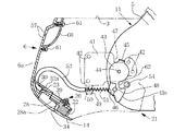
帽体2には、左右一対の補助帽体ロック機構21が組み込まれている。そして、これら一対の補助帽体ロック機構21は、図4〜図6に明示するように、補助帽体6をその下降位置において主帽体2にロックする機能をそれぞれ有し、ロック解除操作手段またはロック解除操作部材としての共通のリリース・ボタン22によってロック解除されるように構成されている。
【0020】
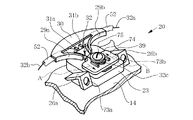
リリース・ボタン22は、補助帽体6のほぼ中央部分(すなわち、使用者の顎の先端に対向する部分)において、図7〜図9に示すように、補助帽体用の外側シェル14とボタン保持部材23とからなる操作部材保持機構としてのボタン保持機構20によって、直線往復摺動可能に保持されている。なお、このボタン保持部材23は、ポリアセタール樹脂、ABS樹脂などの合成樹脂のような適当な材料から成っている。そして、このボタン保持部材23は、その上面のほぼ中央部分に前後方向に延びる長孔24を有しほぼ箱蓋形状に構成されている部材本体25を備えている。また、この部材本体25の左右両側には、ねじ挿通孔27をそれぞれ有する左右一対のほぼヘ字状の取付け片部26a、26bが一体成形され、部材本体25の上面前端附近には、左右一対の弯曲片部29a、29bを有するガイド部30が一体成形され、部材本体25の前端面には、左右一対の補助ガイド板部31a、31bが一体成形されている。そして、補助帽体用の外側シェル14のほぼ中央部分(すなわち、使用者の顎部の先端に対向する部分)には、ボタン保持部材23を取付けるための左右一対の取付けボス部33a、33bが一体成形され、また、これら一対の取付けボス部33a、33bの間には、指挿入用の開孔34が形成されている。
【0021】
リリース・ボタン22は、図7〜図8に示すように、ナイロン6、ABS樹脂などの合成樹脂のような適当な材料からほぼブロック形状に形成され、その下面の一半部分には指入れ用の欠如部28が形成されている。そして、この欠如部28によって、リリース・ボタン22を指で押圧操作するための押圧面(すなわち、開孔34とほぼ直交する面)28aがリリース・ボタン22に形成されている。さらに、このリリース・ボタン22の上面のほぼ中央部分には、ねじ穴36を有する柱状部35が一体成形され、また、この柱状部35から延びる左右一対のほぼL字状の腕部37a、37bおよび突起部38もそれぞれ一体成形されている。
【0022】
リリース・ボタン22に取付け固定されている線条体取付け部材としてのワイヤ取付け部材39は、図7〜図8に示すように、ナイロン6、ABS樹脂などの合成樹脂のような適当な材料からほぼ板状に形成され、そのほぼ中央部分には前後方向に延びる長孔40が形成されている。そして、この長孔40の後端附近の外側シェル14とは反対側の面には、線条体係止部としてのほぼ半円形状のワイヤ係止部71が一体成形などにより形成され、このワイヤ係止部71の左右両側には、左右一対の突条部72a、72bが一体成形などにより形成されている。
【0023】
リリース・ボタン22は、補助帽体用の外側シェル14とボタン保持部材23とからなるボタン保持機構20内に直線往復摺動可能に収納されている。なお、この収納に当たっては、まず、ボタン保持部材23内にリリース・ボタン22が直線往復摺動可能に嵌合され、この嵌合に当たっては、ボタン保持部材23の長孔24にリリース・ボタン22の柱状部35、左右一対の腕部37a、37bおよび突条部38が挿入される。この場合、一対の腕部37a、37bは長孔24の縁部に沿って直線往復摺動可能に保持される。また、リリース・ボタン22の左右両側面および上面もボタン保持部材23の部材本体25の左右両内側面および下面にそって直線往復摺動可能に保持される。
【0024】
ついで、リリース・ボタン22を嵌合させたボタン保持部材23は、補助帽体用の外側シェル14に取付け固定される。そして、この取付け固定は、取付け片部26a、26bのねじ挿通孔27に挿通させた左右一対の取付けねじ73a、73bを補助帽体用の外側シェル14の左右一対の取付けボス部33a、33bにねじ込み固定することによって行われる。したがって、リリース・ボタン22は、ボタン保持部材23に対して、図4および図7の矢印AおよびBに示す方向に往復摺動可能になっている。
【0025】
ついで、ワイヤ取付け板39がリリース・ボタン22に取付け固定される。そして、この取付け固定は、取付けねじ75をワッシャ74およびワイヤ取付け部材39の長孔40にそれぞれ挿通させてからリリース・ボタン22の柱状部35のねじ孔36にねじ込み固定することによって行われる。この場合、ワッシャ74はワイヤ取付け部材39のワイヤ係止部71および左右一対の突条部72a、72b上に載置され、ワイヤ取付け部材39はリリース・ボタン22の左右一対の腕部37a、37bおよび突条部38上に載置される。
【0026】
取付けねじ75をねじ孔36に少しねじ込んだときに、牽引用可撓性線条体としての金属製などの牽引用ワイヤ32の中間部分(この場合には、丁度ほぼ真中の部分)32cをワイヤ取付け部材39のワイヤ係止部71のほぼ円弧状の部分にほぼU字状に引っ掛けてから、取付けねじ75をねじ孔36にねじ込み固定する。この場合、このねじ込み固定に先立って、ワイヤ取付け部材39を長孔40を利用して前後に直線移動させることによって、このワイヤ取付け部材39のリリース・ボタン22に対する前後方向の取付け位置を調整することができるので、牽引用ワイヤ32の張り具合を調整して不必要なたるみを除去することができる。なお、牽引用ワイヤ32は、左右一対の補助帽体ロック機構21に共通に用いられている。すなわち、牽引用ワイヤ32は、U字状中間部分32cの両端にそれぞれ連なる左右一対のワイヤ部32a、32bを有していて、右側(すなわち、ヘルメット1の正面に向って右側、以下同じ)のワイヤ部32a(以下、「牽引用ワイヤ32a」という)は、右側の補助帽体ロック機構21に用いられ、左側(すなわち、ヘルメット1の正面に向って左側、以下同じ)のワイヤ部32b(以下、「牽引用ワイヤ32b」という)は、左側の補助帽体ロック機構21に用いられている。ここで、右側の補助帽体ロック機構21と左側の補助帽体ロック機構21とは互いに左右対称的に構成されているので、以下において、右側の補助帽体ロック機構21について図4〜図6を参照して説明し、左側の補助帽体ロック機構21の説明は省略する。
【0027】
図4〜図6において、補助帽体6の右側耳部6bの内周面には、ステンレス・スチールなどの金属やABS樹脂などの合成樹脂のような適当な材料からなる取付け基板41が取付けねじ42により取付け固定されている。そして、この取付け基板41には、可動側ロック手段または可動側ロック部材としてのロックレバー43が取付けねじ44により往復回動可能に軸支されている。また、このロックレバー43の一端部には、平板状の立上り部からなる被ストッパ部45が一体に形成され、他端部には、L字板状の立上り部からなるワイヤ取付け部46が一体に形成されている。そして、被ストッパ部45は取付け基板41に設けられた切込み47に挿入されているので、ロックレバー43はその往回動位置および復回動位置を取付け基板41により規制される。また、ワイヤ取付け部46はロックレバー43に基端部を植設された取付けロッド48の先端部を固定し、この取付けロッド48には牽引用ワイヤ32aの自由端部が止着されている。
【0028】
取付け基板41には、ほぼカップ状であってよいばね受け部49が一体成形または接着による取付けによって設けられ、このばね受け部49のワイヤ挿通孔50には牽引用ワイヤ32aが挿通されている。また、牽引用ワイヤ32aは、合成ゴムなどの適当な弾性材料からなるチューブ52に挿通されている。そして、このチューブ52の一端部はボタン保持部材23の弯曲片部29aおよび補助ガイド板部31aにより位置保持されて部材本体25aの前端面63に当接され、他端部はばね受け部49に当接されている。なお、左側の補助帽体ロック機構21に用いられている同様のチューブ52の一端部も、ボタン保持部材23の弯曲片部29bおよび補助ガイド板部31bにより位置保持されて部材本体25の前端面63に当接されている。
【0029】
ばね受け部49とロックレバー43のワイヤ取付け部46との間には、牽引用ワイヤ32aを挿通させた反撥用コイルばね51が介装されている。このために、ロックレバー43はこのコイルばね51により取付けねじ44を中心として図4の反時計方向に回動付勢されている。また、ロックレバー43が図4の反時計方向に回動付勢されているために、リリース・ボタン22は牽引用ワイヤ32aにより図4および図7の矢印Bで示す復動方向に牽引付勢されている。
【0030】
リリース・ボタン22は牽引用ワイヤ32aによる牽引付勢力に逆らって図4および図7の矢印Aで示す方向に往動することができる。そして、このリリース・ボタン22の往動方向Aは、図4に示すように、補助帽体6の下降方向(すなわち、取付けねじ7を支点とする復回動方向)Cに対して鋭角θをなしている。なお、この鋭角θは、図示の実施例の場合には約25°であるが、実用性の観点から見て、0°〜60°であるのが好ましく、0°〜45°であるのがさらに好ましい。また、リリース・ボタン22の往動方向Aは、補助帽体6の下降方向Cよりも内側(すなわち、図4における後方側)に向っているが、必ずしも内側に向かう必要はなく、外側に向っていてもよい。しかし、リリース・ボタン22の往動操作と補助帽体6の上昇操作とをきわめて円滑に行えるようにするためには、リリース・ボタン22の往動方向Aは、補助帽体6の下降方向Cよりも内側に向っているのが好ましく、この場合、上記鋭角θは5°〜45°であるのが特に好ましい。
【0031】
主帽体5の外側シェル11の外周面の下端附近には、固定側ロック手段または固定側ロック部材としての左右一対のロックピン54が突設され、これらのロックピン54には、左側および右側の補助帽体ロック機構21のロックレバー43がこれらの回動位置に応じてそれぞれ選択的に係合する。また、ロックレバー43には、ロックピン54が当接する当接部43aが形成され、ロックピン54が係合するためのロック用凹部62がこの当接部43aに隣接して設けられている。
【0032】
なお、ロック機構21の各部(取付け基板41、コイルばね51、ロックレバー43、取付けロッド48、取付けねじ42、44など)、リリース・ボタン22、ボタン保持機構20(ボタン保持部材23、取付けボス部33a、33bなど)、ワイヤ取付け部材39、ワッシャ74、取付けねじ73a、73b、75、チューブ52、牽引用ワイヤ32a、32bなどは、補助帽体用外側シェル14の内側面に沿って配置されている。このために、前記補助帽体用衝撃吸収ライナの外側シェル14に対向する側の面には、これらの各部を収納する凹部や条溝が形成されている。
【0033】
主帽体5の額部の外周面には、図1〜図3に示すように、額部用通気孔形成部材55が取付けられている。また、補助帽体6の外周面の右側部分には、シールド板4の復動位置を規制するストッパ56が設けられ、補助帽体6の顎覆い部6aには、各種の通気孔57、58、59が形成されている。そして、顎覆い部6aの内周面には、空気ガイド板60が通気孔57に対向するように取付けねじ61により取付けられている。したがって、通気孔57から帽体2内に流入する空気は、空気ガイド板60の前面側にガイドされて帽体2内をシールド板4の内側面に向って上昇する。
【0034】
つぎに、上述のように構成されたジェット型兼用のフルフェイス型ヘルメット1の使用方法について説明する。
【0035】
このヘルメット1をフルフェイス型として機能させたいときには、補助帽体6が図3に示すように上昇位置にあれば、この補助帽体6を取付けねじ7を支点として下方に復回動させることにより図1および図2に示す下降位置に持ち来たす。
【0036】
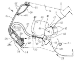
この場合、図6に示すように補助帽体6に設けられたロックレバー43の当接部43aがロックピン54に当接する。したがって、このロックレバー43は、ロックピン54に押されるので、コイルばね51の付勢力に逆らって取付けねじ44を支点として図6の時計方向に少し往回動し、このために、ロックピン54は図4に示すようにロックレバー43の当接部43aを乗り越えてロック用凹部62に係合する。よって、補助帽体6は左右一対のロック機構21により主帽体5にしっかりとロックされれるので、帽体2はフルフェイス型として機能する。
【0037】
つぎに、図1および図2に示すフルフェイス型として機能しているヘルメット1を図3に示すジェット型として機能させたいときには、図4に示す状態において、補助帽体6の顎覆い部6aの外周面のほぼ中央部にある開孔34からリリース・ボタン22の欠如部28に指(例えば、人指指および/または中指)を挿入して、この指でリリース・ボタン22の押圧面28aをコイルばね51の付勢力に逆らって図4の矢印Aで示す往動方向に押し下げる。この場合、押圧面28aはリリース・ボタン22の往動方向Aとほぼ直交しているから、指からリリース・ボタン22に加わる力の方向はこの往動方向Aとほぼ一致している。
【0038】
このとき、リリース・ボタン22がコイルばね51の付勢力に逆らって矢印Aで示す方向に往動するので、牽引用ワイヤ32aは、リリース・ボタン22に牽引され、この牽引時にボタン保持部材23の弯曲片部29aに沿って摺動する。このために、図4に示す状態にあるロックレバー43は取付けねじ44を支点として時計方向に往回動して図5に示す状態となるので、主帽体5に対する補助帽体6のロック機構21によるロックは解除される。したがって、これと同時に、補助帽体6の下端のほぼ中央部に指(例えば、親指)を掛けて(例えば、欠如部28に挿入した人指指および/または中指と上記下端のほぼ中央部に掛けた親指とで補助帽体6を上下からつかんで)、補助帽体6を上方に持ち上げれば、補助帽体6は取付けねじ7を支点として上方へ回動し、図6に示す状態を経て図3に示す状態になるので、帽体2はジェット型として機能する。
【0039】
なお、上述の第1の実施例においては、牽引用ワイヤ32a、32bをそれぞれチューブ52に挿通させている。しかし、これらのチューブ52は必要に応じてそれぞれ省略することができる。そして、このように省略した場合には、牽引用ワイヤ32a、32bは、ボタン保持部材23のガイド板部30の弯曲片部29a、29bと取付け基板41のばね受け部49との間においてほぼ直線的に延びる長さに選定されているのが好ましい。
【0040】
第2の実施例
つぎに、本発明をジェット型兼用のフルフェイス型ヘルメットに適用した第2の実施例を図10〜図22を参照して説明する。
【0041】
この第2の実施例による図10〜図22に示すヘルメットは、つぎの(1)項〜(7)項に記載の相違点およびこれらの関連事項を除いて、既述の第1の実施例による図1〜図9に示すヘルメットと実質的に同一の構成、作用および効果を有している。したがって、以下において、これらの(1)項〜(7)項に記載の相違点およびこれらの関連事項についてのみ説明し、この第2の実施例による図10〜図22に示すヘルメットと既述の第1実施例による図1〜図9に示すヘルメットとで共通の部分には互いに同一符号を付して上記相違点およびこれらの関連事項以外についての説明は省略する。
【0042】
(1) 補助帽体6を主帽体5に支持するための左右一対の支持板81が主帽体5に設けられていること、
(2) 補助帽体6を主帽体5に取付けるための取付けねじ7をカバーするカバー部材17が省略されていること、
(3) ボタン保持機構20のボタン保持部材23に指当て板部83が設けられていること、
(4) 補助帽体ロック機構21の取付け基板41に補助基板82が設けられていること、
(5) 左右一対の牽引用ワイヤ32a、32bが挿通されている左右一対のチューブ52が省略されていること、
(6) ボタン保持機構20のワイヤ取付け部材39が上下逆向きに配置されていること、
(7) 補助帽体6の顎覆い部6aに形成されている通気孔59の構成が変更されていること、
【0043】
上記(1)項および(2)項について
左右一対の支持板81は、それぞれ、図11および図12に示すように、ほぼ前後方向に延びる長手状の板状体であって、ボタン保持部材23についてすでに述べた材料と同様の材料からなっていてよい。そして、支持板81は、その前端部附近を取付けねじ84によって主帽体用の外側シェル11に止着され、また、その後端部附近を補助帽体6の耳部6bとともに取付けねじ(軸支手段)7によって主帽体用の外側シェル11に止着されている。なお、既述の第1の実施例において設けられていたこの取付けねじ7のためのカバー部材17は、この第2の実施例では省略されている。
【0044】
支持板81には、図21および図22に示すように、付勢手段としてのばね85の中央部分に設けられたコイル部85aに嵌合する突起部86が一体成形などにより形成されている。また、ばね85は、ねじりコイルばねとして機能するものであって、コイル部85aから互いにほぼ逆方向に延びる第1および第2の線条部85b、85cをさらに有している。そして、支持板81には、第1の線条部85bが係止される一対のばね掛け用突起部87、88が一体成形などにより形成され、第1の線条部85bはこれら一対の突起部87、88の間に挿入されている。
【0045】
補助帽体6の左右一対の耳部6bにおける外側シェル14の内側面には、図21および図22に示すように、位置決め手段としての左右一対の突起部89が突設されている。また、ばね85の第2の線条部85cはほぼ円弧状に弯曲し、そして、この円弧状の第2の線条部85cには、図11および図21に示すように補助帽体6が下降位置にあるときには、上記ばね掛け用突起部89が圧接している。
【0046】
支持板81には、図11に示すように補助帽体6が下降位置にあるときに、位置決め用突起部89が図21に示すように軽く係合または嵌合して比較的小さな作用力で補助帽体6の移動を阻止する位置決め手段としての左右一対の凹部90が形成されている。したがって、突起部89が凹部90に係合または嵌合しているときには、ばね85による補助帽体6の上昇方向への付勢力の全部または一部をこの係合または嵌合により低減させることができる。したがって、下降位置にある補助帽体6は、左右一対の補助帽体ロック機構21により下降位置にロックされるだけでなく、位置決め手段89、90による凹凸係合によっても、下降位置に軽く位置保持されて往動方向への移動を比較的小さな作用力で阻止されている。また、ばね85は、上記凹凸係合が解除されたときに補助帽体6の上昇を円滑に行うために、補助帽体6を上昇方向(すなわち、往動方向)に付勢している。さらに、ばね85は、補助帽体6を主帽体5に対して取付けねじ(軸支手段)7を支点として図11および図13の時計方向に付勢しているので、ヘルメット1の振動などによりロックレバー43のロック用凹部62からロックピン54が不測に抜け出すのを防止している。
【0047】
支持板81には、図12に示すように補助帽体6が上昇位置にあるときに、位置決め用突起部89が図22に示すように係合するほぼ半円筒形状のストッパ用突起部91が一体成形などにより形成されている。また、支持板81には、補助帽体6が下降位置から上昇位置に至る直前において位置決め用突起部89が次第に乗り上がる傾斜面を有するストッパ用突起部92が、ストッパ用突起部91に隣接して一体成形などにより形成されている。したがって、補助帽体6が下降位置から上昇位置に至る直前において位置決め用突起部89がストッパ用突起部92の傾斜面に乗り上がってからこの突起部92を通過し、この結果、図22に示すように、ストッパ用突起部91によって往動方向へのそれ以上の移動を完全に阻止されるとともに、ストッパ用突起部92によって復動方向への移動を比較的小さな作用力で阻止される。
【0048】
上記(3)項について
ボタン保持機構20のボタン保持部材23の部材本体25の後端面には、ほぼ垂直な指当て面83aを有する指当て板部83が一体成形などにより形成されている。なお、上記指当て面83aはその左右両側端部および下端部にそれぞれ突条部93a、93b、94を有し、これらの突条部93a、93b、94は全体としてU字状になっている。したがって、補助帽体6を上方に持ち上げるときに、既述の第1の実施例の場合のように補助帽体6の下端のほぼ中央部に指を掛ける代わりに、この指当て部材83の指当て面83aに指(例えば、親指)を掛けてから、補助帽体6を上方に持ち上げれば、この持ち上げ操作を円滑に行うことができる。
【0049】
なお、外側シェル14には、補助帽体6の顎覆い部6aの下端のほぼ中央部において、指当て部材83の形状に応対して前方にやや膨出した膨出部95が設けられている。
【0050】
上記(4)項について
既述の第1の実施例における取付け基板41は、この第2の実施例においては、図13および図17に示すように、主要な取付け基板41と補助取付け基板82とからなっている。この場合、補助取付け基板82は、取付け基板41についてすでに述べた材料と同様の材料からなっていてよいが、主要な取付け基板41が金属製で補助取付け基板82が合成樹脂製であるのが好ましい。
【0051】
取付け基板41は、図17に示すように、平板形状であってよく、また、この取付け基板41には、一対のボス挿通孔101a、101b、リベット挿通孔102、ボス挿通孔103およびねじ挿通孔104がそれぞれ形成されている。そして、既述の第1の実施例においてはこの取付け基板41に設けられていたばね受け部49は、この第2の実施例においては補助取付け基板82に一体成形などにより設けられている。また、補助取付け板82は、ほぼ中央部分に段部82aを有し、また、この段部82aの両側にそれぞれ前板部82bおよび後板部82cを有している。そして、この後板部82cには、一対のねじ挿通用のボス部105a、105bおよびばね受け部49が一体成形などにより形成されている。
【0052】
左右一対の牽引用ワイヤ部32a、32bの自由端には、図13および図17に示すように、金属製などの球状体106が止着されている。また、ロックレバー43のワイヤ取付け部46には、ほぼ半円形状の係止用欠如部107が形成され、ロックレバー43のレバー本体109には、この係止用欠如部107の外側シェル14とは反対側においてほぼ円形状の係止用開孔108が形成されている。そして、ロックレバー43のレバー本体109とワイヤ取付け部46との間に牽引用ワイヤ部32a、32bの自由端附近を上方から挿入して球状体106を欠如部107および開孔108にそれぞれ嵌合させることによって、牽引用ワイヤ部32a、32bの自由端をロックレバー43に止着している。
【0053】
外側シェル14の内側面には、図13および図17に示すように、補助帽体6の顎覆い部6aの左右両側において、それぞれほぼ水平に延びる上下一対の突条部111a、111bが一体成形などにより形成され、また、これらの突条部111a、111bに隣接して上下一対のねじ止め用ボス部112a、112b、位置決め用ボス部113およびねじ止め用ボス部114がそれぞれ一体成形などにより形成されている。そして、一対の突条部111a、111bの間には、牽引用ワイヤ部32a、32bのほぼ中間の部分がある程度位置決めされるように介装されている。また、ロックレバー43のレバー本体109に形成されているリベット挿入孔115と取付け基板41のリベット挿入孔102とにそれぞれ挿入されたリベット116によって、ロックレバー43が取付け基板41にリベット止めされている。そして、位置決め用ボス部113を取付け基板41のボス挿通孔103に嵌合させるとともに、取付け基板41の前面をねじ止め用ボス部114の先端面に当接させてから、ねじ117を取付け基板41のねじ挿通孔104に挿通させてねじ止め用ボス部114にねじ込むことによって、取付け基板41を外側シェル14の内側面に固定している。
【0054】
取付け基板41のボス挿通孔101a、101bには、図13および図17に示すように、一対のねじ止め用ボス部112a、112bが挿通されるとともに、これらのボス部112a、112bの先端面は補助取付け板82の前板部82bの前面に当接している。そして、上下一対のねじ118a、118bをねじ挿通用のボス部105a、105bにそれぞれ挿通させてからねじ止め用ボス部112a、112bにそれぞれねじ込むことによって、補助取付け板82および取付け基板41を外側シェル14の内側面に固定している。
【0055】
上述の構成によれば、図16に示すように、取付け基板41およびロックレバー43と補助取付け基板82の後板部82cとの間に間隙121が形成されている。したがって、補助取付け基板82は、間隙形成部材としても機能している。そして、補助帽体6が図13および図14に示す下降位置およびこの下降位置からやや上昇した図15に示す中間位置の間においては、この間隙121には、主帽体5の外側シェル11の下端附近が挿入されているので、この外側シェル11の下端附近(ひいては、ロックピン54)と補助帽体6のロックレバー43とが外側シェル11の厚さ方向において相対的にある程度位置決めされる。したがって、ロックピン54がロックレバー43のロック用凹部62から不測に相対的に離脱したりロックレバー43の当接部43aから不測に相対的に離間したりすることなどを、ある程度防止することができる。なお、外側シェル11の下端附近を外側面および必要な場合には内側面も被覆するカバー部材(図示せず)を設け、このカバー部材にロックピン54を固定するようにしてもよい。そして、このカバー部材はボタン保持部材23についてすでに述べた材料と同様の材料からなっていてよい。
【0056】
外側シェル14の内側面には、補助帽体6の顎部6aの左右両側において、左右一対の補助取付け板82が設けられているので、間隙121も左右一対形成されている。そして、これら左右一対の間隙121に主帽体5の外側シェル11の左右一対の下端附近がそれぞれ挿入される。なお、この挿入量は、補助帽体6が図13および図14に示す下降位置では最大であり、補助帽体6が図13および図14に示す下降位置から図15に示すやや上昇した中間位置に往動するにしたがって次第に減少する。そして、補助帽体6が図15に示す中間位置からさらに上昇すると、外側シェル11の左右一対の下端附近は左右一対の間隙121から完全に離脱する。また、補助帽体6の下降時には、上述の場合とちょうど逆の動作が行われる。
【0057】
上記(5)項について
既述の第1の実施例においては、左右一対の牽引用ワイヤ部32a、32bを挿通させている左右一対のチューブ52が設けられているが、この第2の実施例においては、このようなチューブ52は省略されている。このために、牽引用ワイヤ部32a、32bは、ボタン保持部材23のガイド板部30の弯曲片部29a、29bと補助取付け基板41のばね受け部49との間においてほぼ直線的に延びている。
【0058】
上記(6)項について
この第2の実施例においては、ボタン保持機構20のワイヤ取付け部材39は、図18および図19に示すように、既述の第1の実施例の場合とは上下逆向きに配置されている。このために、ワイヤ係止部71および左右一対の突条部72a、72bは、外側シェル14側の面において、ワイヤ取付け部材39に形成されている。
【0059】
また、図18および図20に示す組み立て後の状態においては、ワイヤ取付け部材39の左右一対の突条部72a、72bの間にリリース・ボタン(ロック解除操作部材)22の左右一対の腕部37a、37bが嵌合している。換言すれば、左右一対の突条部72a、72bの間に形成されている凹部に、左右一対の腕部37a、37bによって形成された凸部(この凸部の中間部分、すなわち一対の腕部37a、37bの間は欠如部となっている)が直線往復摺動可能に凹凸嵌合している。
【0060】
また、これら左右一対の腕部37a、37bの間にワイヤ取付け部材39のワイヤ係止部71が挿入されている。そして、牽引用ワイヤ32のU字状の中間部分32cは、ワイヤ係止部71に引っ掛けられるとともにリリース・ボタン22の柱状部35の左右両側にも当接している。したがって、上記中間部分32cは、リリース・ボタン22の左右一対の腕部37a、37bの基端部分とワイヤ取付け部材39の外側シェル14の側の面とによって両側からしっかりと挾持されている。
【0061】
さらに、既述お第1の実施例においてはリリース・ボタン22の一対の腕部37a、37bがボタン保持部材23の長孔24の縁部に沿って直線往復摺動するが、この第2の実施例においてはワイヤ取付け部材39の一対の突条部72a、72bが上記長孔24の縁部に沿って直線往復摺動する。
【0062】
上記(7)項について
既述の第1の実施例においては、補助帽体6の顎覆い部6aには、比較的大きな通気孔59が左右一対設けられているが、この第2の実施例においては、比較的小さくかつ相前後して配された2つの通気孔59が左右一対ずつ設けられている。
【0063】
以上において、本発明の第1および第2の実施例につき詳細に説明したが、本発明は、これら第1および第2の実施例に限定されるものではなく、特許請求の範囲に記載された発明の趣旨に基づいて各種の変更および修正が可能である。
【0064】
例えば、上述の第1および第2の実施例においては、リリース・ボタン22の押圧面28aと直交する方向がこのリリース・ボタン22の往動方向Aとほぼ一致するように構成した。しかし、これら両者の方向は多少不一致であっても差し支えなく、この場合でも、リリース・ボタン22の押圧面28aの直交方向と補助帽体6の下降方向Cとのなす鋭角θ′は、鋭角θについて既述したのと同様の角度範囲を有していてよい。
【0065】
【発明の効果】
本発明によれば、ロック機構による補助帽体のロックを解除するための機構を比較的簡単な構造にすることができ、また、上記ロック解除の動作およびその逆のロック動作を迅速かつ円滑に行わせることができる。
【0066】
また、請求項7に記載した発明によれば、ヘルメット使用者の顎部を覆う下降位置にある補助帽体の主帽体に対するロックを解除するためにロック解除操作部材を往動方向に押圧操作したときに、まず、主帽体に対する補助帽体のロックが解除され、ついで、上記押圧操作の方向とは反対側の方向に補助帽体を持ち上げたときに、この補助帽体を下降位置から上昇位置へと上昇させることができる。したがって、ロック解除操作部材を誤って往動方向に押圧操作したり、あるいはまた、ロック解除操作部材に異物が不測に当接したりしても、この押圧操作または異物の当接が続いただけでは補助帽体が下降位置から上昇することはないから、自動二輪車を高速度で運転しているときに補助帽体が誤ってまたは不測に下降位置から上昇してヘルメット使用者の顎部に大きな風圧が直接加わるおそれがない。
【図面の簡単な説明】
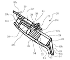
【図1】本発明をジェット型兼用のフルフェイス型ヘルメットに適用した第1の実施例におけるヘルメット全体の、通常の使用状態での斜視図である。
【図2】図1に示すヘルメット全体の、通常の使用状態での右側面図である。
【図3】図1に示すヘルメット全体の、補助帽体を上昇させた状態での右側面図である。
【図4】図2に示すヘルメットの、補助帽体ロック機構を説明するための、補助帽体用の裏当て部材および縁部材を省略した状態での部分的な中央縦断面図である。
【図5】リリース・ボタンを押圧操作したときの、図4と同様の図である。
【図6】図5に示す状態から補助帽体を多少上昇させたときの、図4と同様の図である。
【図7】図4に示すリリース・ボタンおよびその保持機構の斜視図である。
【図8】図7に示すリリース・ボタンおよびその保持機構の分解斜視図である。
【図9】図7に示すリリース・ボタンおよびその保持機構の中央縦断面図である。
【図10】本発明をジェット型兼用のフルフェイス型ヘルメットに適用した第2の実施例におけるヘルメット全体の、通常の使用状態での斜視図である。
【図11】図10に示すヘルメット全体の、通常の使用状態での右側面図である。
【図12】図10に示すヘルメット全体の、補助帽体を上昇させた状態での右側面図である。
【図13】図11に示すヘルメットの、補助帽体ロック機構を説明するための、補助帽体用の裏当て部材および縁部材を省略した状態での部分的な中央縦断面図である。
【図14】リリース・ボタンを押圧操作したときの、図13と同様の図である。
【図15】図14に示す状態から補助帽体を多少上昇させたときの、図13と同様の図である。
【図16】図13のXVI −XVI 線に沿った断面図である。
【図17】図13に示す右側補助帽体ロック機構の要部の分解斜視図である。
【図18】図13に示すリリース・ボタンおよびその保持機構の斜視図である。
【図19】図18に示すリリース・ボタンおよびその保持機構の分解斜視図である。
【図20】図18に示すリリース・ボタンおよびその保持機構の中央縦断面図である。
【図21】図11のXXI −XXI 線に沿った断面図である。
【図22】図12のXXII−XXII線に沿った断面図である。
【符号の説明】
2 ジェット型兼用のフルフェイス型帽体
5 主帽体
6 補助帽体
7 取付けねじ(軸支手段)
20 ボタン保持機構(操作部材保持機構)
21 補助帽体ロック機構
22 リリース・ボタン(ロック解除操作部材)
23 ボタン保持部材
32 牽引用ワイヤ(可撓性線条体)
39 ワイヤ取付け部材(線条体取付け部材)
43 ロックレバー(可動側ロック部材)
82 補助取付け基板(間隙形成部材)
85 ばね(付勢手段)
89 突起部(第2の位置決め手段)
90 凹部(第1の位置決め手段)
A 往動方向
C 下降方向
θ 鋭角[0001]
BACKGROUND OF THE INVENTION
The present invention includes a head protector (herein simply referred to as “cap body”) that a helmet user such as a motorcycle rider wears on the head to protect the head. The present invention relates to a helmet having a cap-shaped main cap body and an auxiliary cap body that is attached to the main cap body so as to be able to be lifted and lowered so as to selectively cover the jaw portion of the helmet user.
[0002]
[Prior art]
Conventionally, as a riding helmet used by motorcycle riders, etc., a full-face type in which the chin cover covering the chin of the helmet user is formed integrally with the cap body, and almost the face of the helmet user's face A jet type in which a chin cover is not formed on a cap body so that the whole can be exposed is known. In addition, in order to combine the functions of both a full-face helmet and a jet helmet, the main cap body having almost the same shape as that of the jet helmet and the chin of the helmet user are selectively covered. A full-face helmet (hereinafter referred to as a “jet-type full-face helmet”), which has a cap body made up of an auxiliary cap body that is attached to the main cap body so as to be able to move up and down, is also known. Are known.
[0003]
In such a conventional jet-type full-face helmet, the auxiliary cap functions as a chin covering means when the auxiliary cap is in the lowered position, and when the auxiliary cap is in the raised position. Since the entire large window provided in the main cap body is opened, the cap body does not have the chin covering means as in the case of the jet helmet. When a user wearing such a jet-type full-face helmet is driving a motorcycle at high speed, the helmet prevents a large wind pressure from being applied around the user's jaw. Therefore, the auxiliary cap body is used in a state where it is lowered to the lowered position. In addition, the helmet has an auxiliary cap locking mechanism that locks the auxiliary cap in the lowered position with respect to the main cap so that the auxiliary cap does not rise alone due to a large impact or large wind pressure during such high-speed driving. Is provided.
[0004]
Such a lock mechanism includes a release button as an unlocking operation means or an unlocking operation member so that the lock at the lowered position of the auxiliary cap body can be released. When the release button is pressed to release the lock, a force for moving the auxiliary cap body from the lowered position to the raised position is applied to the auxiliary cap body alone. In other words, when the release button is pressed upward, the lock at the lowered position of the auxiliary cap body is released. For this reason, when the release button is pressed upward to unlock the auxiliary cap body, the lock of the auxiliary cap body by the lock mechanism is released, and the release button is continuously pressed, The auxiliary cap body can be started to move from the lowered position to the raised position. Accordingly, the user can quickly and continuously perform the unlocking of the auxiliary cap body and the raising operation of the unlocked auxiliary cap body simply by pressing the release button.
[0005]
[Problems to be solved by the invention]
However, in the conventional full-face helmet used for jet type as described above, when the user is driving the motorcycle at a high speed, for example, a shield plate (this shield plate is the front of the helmet body). (Attached to the auxiliary cap body so that the window hole formed in the window can be opened and closed) is pushed up slightly to open the window hole blocked by this shield plate, and the release button is accidentally If a foreign object comes into contact with the release button from below or if the foreign object comes into contact with the release button from below, the lock at the lowered position of the auxiliary cap body is released and the auxiliary cap body moves to a certain extent from the lowered position. It will rise. For this reason, since there is a possibility that a large wind pressure is directly applied to the user's jaw, there is a possibility that inconvenience may arise in the operation of the motorcycle by the user.
[0006]
Further, in the conventional full-face helmet that is also used as a jet type as described above, the mechanism for unlocking the auxiliary cap body by the lock mechanism has a complicated structure, and the unlocking operation and vice versa. There is a possibility that the locking operation is difficult to be performed quickly and smoothly.
[0007]
The present invention is to make it possible to remedy the above-mentioned drawbacks of the conventional jet-type full-face helmet extremely effectively with a very simple configuration.
[0008]
[Means for Solving the Problems]
The present inventionA cap body attached to the head of the helmet user, and a cap-shaped main cap body, and an auxiliary cap body that is attached to the main cap body so as to be movable up and down so as to selectively cover the helmet user's jaw. And when the auxiliary cap body is in a lowered position covering the jaw,Left and right side ofFor the main cap bodyRespectivelyLockFirst and secondA locking mechanism is provided on the cap body,First and secondThe lock of the auxiliary cap body by the lock mechanismIn commonMoved forward to releaseCommonAn unlocking operation member is provided on the auxiliary cap body.A common pulling flexible filament that commonly transmits the forward movement of the unlocking operation member to the first and second movable side locking members of the first and second locking mechanisms. An end of the linear body is coupled to the first movable side locking member, and the other end of the linear body is coupled to the second movable side locking member, and the lock is released. The operation member is provided with a striated body locking portion, and an intermediate portion of the striated body is locked to the striated body locking portion.It concerns a helmet.And in this invention, according to the 1st viewpoint, the said linear body latching | locking part is formed in the substantially semicircle shape in the linear body attachment member attached to the said unlocking operation member, The said line | wire An intermediate portion of the strip can be hooked and locked in a substantially U shape on a substantially arc-shaped portion of the substantially semicircular linear strip locking portion. In the present invention, according to the second aspect, the linear body mounting member is attached to the unlocking operation member by sliding the linear body mounting member with respect to the unlocking operation member. The linear body attachment member may be attached to the unlocking operation member so that the slack of the linear body can be removed by adjusting the position.
[0009]
Furthermore, according to the third aspect of the present invention, there is provided an operation member holding mechanism for holding the unlocking operation member so as to reciprocate, and the operation member holding mechanism is provided with the unlocking operation member. The holding member can have a finger contact surface on which a finger can be applied when the unlocking operation member is moved forward. In the present invention, according to the fourth aspect, when the first and second gap forming members are provided on the left and right sides of the auxiliary cap body, and the auxiliary cap body is at least in the lowered position. The left and right lower end vicinitys of the main cap body are respectively inserted into the first and second gaps formed between the left and right sides of the auxiliary cap body and the first and second gap forming members. Can be configured. According to the fifth aspect of the present invention, in order to prevent the locks in the first and second lock mechanisms from being unnecessarily released, the auxiliary cap body in the lowered position is provided. An urging means for urging the main cap body in the upward direction can be provided. Furthermore, according to the sixth aspect of the present invention, the forward movement direction of the unlocking operation member can be configured to form an acute angle with respect to the descending direction of the auxiliary cap body. And in the said 6th viewpoint of this invention, the said advancing direction of the said unlocking operation member has faced the inner side rather than the said descent | fall direction of the said auxiliary cap body, and the said acute angle is 5 degrees-45 degrees. Can be. In the sixth aspect of the present invention, the auxiliary cap body may be attached to the main cap body so as to be rotatable up and down with respect to the main cap body by a shaft support means. Furthermore, in the sixth aspect of the present invention, there is provided a positioning mechanism for preventing the movement of the auxiliary cap body relative to the main cap body with a relatively small acting force when the auxiliary cap body is in the lowered position. Provided separately from the lock mechanism, the positioning mechanism includes a first positioning means provided on the main cap body, and a second positioning provided on the auxiliary cap body, which is unevenly fitted with the first positioning means. And a biasing means for biasing the auxiliary cap body in the upward direction with respect to the main cap body when the auxiliary cap body is in the lowered position. The force itself can be selected to have such a size that the uneven fitting of the positioning mechanism cannot be released.
[0010]
DETAILED DESCRIPTION OF THE INVENTION
Next, an embodiment in which the present invention is applied to a jet-type full-face helmet will be described with reference to the drawings.
[0011]
First embodiment
First, a first embodiment in which the present invention is applied to a jet-type full-face helmet will be described with reference to FIGS.
[0012]
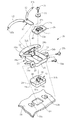
As shown in FIGS. 1 to 3, the jet-type full-
[0013]
As is well known in the art, the
[0014]
As conventionally known, the
[0015]
As is well known in the art, the
[0016]
As is well known in the art, the main cap body backing member includes a main cap body shock absorbing liner attached to the inner peripheral surface of the main cap body
[0017]
As is well known in the art, the
[0018]
As described above, the auxiliary cap body backing member includes an auxiliary cap body shock absorbing liner attached to the inner peripheral surface of the auxiliary cap body
[0019]
The
[0020]
As shown in FIGS. 7 to 9, the
[0021]
As shown in FIGS. 7 to 8, the
[0022]
As shown in FIGS. 7 to 8, the
[0023]
The
[0024]
Next, the
[0025]
Next, the
[0026]
When the mounting
[0027]
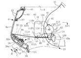
4 to 6, a mounting
[0028]
A
[0029]
Between the
[0030]
The
[0031]
Near the lower end of the outer peripheral surface of the
[0032]
Each part of the lock mechanism 21 (
[0033]
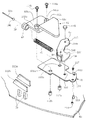
As shown in FIGS. 1 to 3, a forehead ventilation
[0034]
Next, a method of using the jet-type full-
[0035]
When it is desired to make the
[0036]
In this case, as shown in FIG. 6, the
[0037]
Next, when the
[0038]
At this time, since the
[0039]
In the first embodiment described above, the pulling
[0040]
Second embodiment
Next, a second embodiment in which the present invention is applied to a jet-type full-face helmet will be described with reference to FIGS.
[0041]
The helmet shown in FIGS. 10 to 22 according to the second embodiment is the same as the first embodiment described above except for the differences described in the following items (1) to (7) and related matters. Has substantially the same configuration, operation and effect as the helmet shown in FIGS. Therefore, in the following, only the differences described in the items (1) to (7) and the related matters will be described, and the helmet shown in FIGS. Parts common to the helmets shown in FIGS. 1 to 9 according to the first embodiment are denoted by the same reference numerals, and descriptions of the differences and other related matters are omitted.
[0042]
(1) A pair of left and
(2) The
(3) The finger holding
(4) The
(5) The pair of left and
(6) The
(7) The configuration of the
[0043]
Regarding items (1) and (2) above
As shown in FIGS. 11 and 12, each of the pair of left and
[0044]
As shown in FIGS. 21 and 22, the
[0045]
As shown in FIGS. 21 and 22, a pair of left and
[0046]
When the
[0047]
As shown in FIG. 12, the
[0048]
About item (3) above
On the rear end surface of the member
[0049]
The
[0050]
About item (4) above
In the second embodiment, the mounting
[0051]
As shown in FIG. 17, the mounting
[0052]
As shown in FIGS. 13 and 17, a
[0053]
On the inner side surface of the
[0054]
As shown in FIGS. 13 and 17, a pair of screwing
[0055]
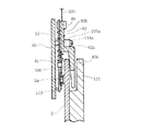
According to the above configuration, the
[0056]
Since a pair of left and right
[0057]
About item (5) above
In the first embodiment described above, a pair of left and
[0058]
About item (6) above
In the second embodiment, the
[0059]
18 and 20, the pair of left and
[0060]
Further, a
[0061]
Further, in the first embodiment, the pair of
[0062]
About item (7) above
In the first embodiment described above, the
[0063]
Although the first and second embodiments of the present invention have been described in detail above, the present invention is not limited to these first and second embodiments, and is described in the claims. Various changes and modifications can be made based on the spirit of the invention.
[0064]
For example, in the first and second embodiments described above, the direction orthogonal to the
[0065]
【The invention's effect】
The present inventionAccording toThe mechanism for unlocking the auxiliary cap body by the lock mechanism can be made to have a relatively simple structure, and the above-described unlocking operation and vice versa can be performed quickly and smoothly.
[0066]
Also,Claim 7According to the invention described inWhen the unlocking operation member is pushed in the forward direction in order to unlock the main cap body of the auxiliary cap body in the lowered position that covers the jaw part of the helmet user, first, the auxiliary cap body with respect to the main cap body When the auxiliary cap body is lifted in the direction opposite to the direction of the pressing operation, the auxiliary cap body can be raised from the lowered position to the raised position. Therefore, even if the unlocking operation member is accidentally pressed in the forward movement direction, or if foreign matter comes into contact with the unlocking operation member unexpectedly, it will be helpful if the pressing operation or foreign matter contact continues. Since the cap body does not rise from the lowered position, the auxiliary cap body accidentally or unexpectedly rises from the lowered position when the motorcycle is operated at a high speed, and a large wind pressure is applied to the helmet user's jaw. There is no risk of direct participation.
[Brief description of the drawings]
FIG. 1 is a perspective view of an entire helmet in a first embodiment in which the present invention is applied to a jet-type full-face helmet, in a normal use state.
FIG. 2 is a right side view of the entire helmet shown in FIG. 1 in a normal use state.
FIG. 3 is a right side view of the entire helmet shown in FIG. 1 with the auxiliary cap body raised.
4 is a partial central longitudinal sectional view of the helmet shown in FIG. 2 in a state in which a backing member and an edge member for the auxiliary cap body are omitted for explaining an auxiliary cap body locking mechanism. FIG.
FIG. 5 is a view similar to FIG. 4 when the release button is pressed.
6 is a view similar to FIG. 4 when the auxiliary cap body is slightly raised from the state shown in FIG. 5;
7 is a perspective view of the release button and its holding mechanism shown in FIG. 4. FIG.
8 is an exploded perspective view of the release button and its holding mechanism shown in FIG.
9 is a central longitudinal sectional view of the release button and its holding mechanism shown in FIG. 7;
FIG. 10 is a perspective view of the entire helmet according to the second embodiment in which the present invention is applied to a jet-type full-face helmet, in a normal use state.
11 is a right side view of the entire helmet shown in FIG. 10 in a normal use state.
12 is a right side view of the entire helmet shown in FIG. 10 with the auxiliary cap body raised.
13 is a partial central longitudinal cross-sectional view of the helmet shown in FIG. 11 in a state in which the backing member and the edge member for the auxiliary cap body are omitted for explaining the auxiliary cap body locking mechanism.
14 is a view similar to FIG. 13 when the release button is pressed. FIG.
FIG. 15 shows a state where the auxiliary cap body is slightly raised from the state shown in FIG.FIG.FIG.
16 is a cross-sectional view taken along line XVI-XVI in FIG.
17 is an exploded perspective view of a main part of the right auxiliary cap body locking mechanism shown in FIG.
18 is a perspective view of the release button and its holding mechanism shown in FIG.
19 is an exploded perspective view of the release button and its holding mechanism shown in FIG.
20 is a central longitudinal sectional view of the release button and its holding mechanism shown in FIG.
21 is a cross-sectional view taken along line XXI-XXI in FIG.
22 is a cross-sectional view taken along line XXII-XXII in FIG.
[Explanation of symbols]
2 Full-face cap for jet type
5 Main cap body
6 Auxiliary cap body
7 Mounting screws (shaft support means)
20 Button holding mechanism (operating member holding mechanism)
21 Auxiliary cap body locking mechanism
22 Release button (lock release operation member)
23 Button holding member
32 Tow wire (flexible wire)
39 Wire attachment members (wire body attachment members)
43 Lock lever (movable lock member)
82 Auxiliary mounting substrate (gap forming member)
85 Spring (biasing means)
89 Projection (second positioning means)
90 recess (first positioning means)
A Forward direction
C descending direction
θ acute angle
Claims (7)
上記補助帽体が上記顎部を覆う下降位置にあるときにこの補助帽体の左側および右側を上記主帽体に対してそれぞれロックする第1および第2のロック機構が、上記帽体に設けられ、
上記第1および第2のロック機構による上記補助帽体の上記ロックを共通に解除するために往動操作される共通のロック解除操作部材が、上記補助帽体に設けられているヘルメットにおいて、
上記ロック解除操作部材の往動操作を上記第1および第2のロック機構の第1および第2の可動側ロック部材に共通に伝達する共通の牽引用可撓性線条体を備え、
上記線条体の一端部が上記第1の可動側ロック部材に結合されるとともに、上記線条体の他端部が上記第2の可動側ロック部材に結合され、
上記ロック解除操作部材に線条体係止部が設けられ、
上記線条体の中間部分が上記線条体係止部に係止されているヘルメット。A cap body attached to the head of the helmet user, and a cap-shaped main cap body, and an auxiliary cap body that is attached to the main cap body so as to be movable up and down so as to selectively cover the helmet user's jaw. And
The cap body is provided with first and second locking mechanisms for locking the left and right sides of the auxiliary cap body to the main cap body when the auxiliary cap body is in a lowered position covering the jaw. And
In a helmet provided with a common unlocking operation member that is operated to move forward in order to commonly release the lock of the auxiliary cap body by the first and second locking mechanisms,
A common traction flexible linear member for commonly transmitting the forward operation of the unlocking operation member to the first and second movable side lock members of the first and second lock mechanisms;
One end of the linear body is coupled to the first movable side locking member, and the other end of the linear body is coupled to the second movable side locking member,
The unlocking operation member is provided with a striatum locking part,
A helmet in which an intermediate portion of the linear body is locked to the linear body locking part.
上記線条体の中間部分が、このほぼ半円形状の線条体係止部のほぼ円弧状の部分にほぼU字状に引っ掛けられて係止されている請求項1に記載のヘルメット。The striated body locking part is formed in a substantially semicircular shape on the striated body attaching member attached to the unlocking operation member,
The helmet according to claim 1 , wherein an intermediate portion of the linear body is hooked and locked in a substantially U-shape to a substantially arc-shaped portion of the substantially semicircular linear body locking portion.
この操作部材保持機構が、上記ロック解除操作部材を保持し得る保持部材を備え、
この保持部材が、上記ロック解除操作部材を往動操作するときに指を当てることができる指当て面を有している請求項1、2または3に記載のヘルメット。An operation member holding mechanism for holding the unlocking operation member so as to be able to reciprocate is provided,
The operation member holding mechanism includes a holding member that can hold the unlocking operation member,
The helmet according to claim 1, 2, or 3 , wherein the holding member has a finger contact surface on which a finger can be applied when the unlocking operation member is moved forward.
上記補助帽体が少なくとも上記下降位置にあるときには、上記補助帽体の左側および右側と上記第1および第2の間隙形成部材との間に形成された第1および第2の間隙に上記主帽体の左側および右側の下端附近がそれぞれ挿入されるように構成した請求項1〜4のいずれか1つに記載のヘルメット。First and second gap forming members are provided on the left and right sides of the auxiliary cap body,
When the auxiliary cap body is at least in the lowered position, the main cap is placed in first and second gaps formed between the left and right sides of the auxiliary cap body and the first and second gap forming members. The helmet according to any one of claims 1 to 4 , wherein the helmet is inserted so that the left side and the right side near the lower end of the body are respectively inserted.
Priority Applications (3)
| Application Number | Priority Date | Filing Date | Title |
|---|---|---|---|
| JP12450299A JP4428754B2 (en) | 1998-07-16 | 1999-04-30 | helmet |
| EP19990113729 EP0972461B1 (en) | 1998-07-16 | 1999-07-13 | Helmet |
| DE69911693T DE69911693T2 (en) | 1998-07-16 | 1999-07-13 | helmet |
Applications Claiming Priority (3)
| Application Number | Priority Date | Filing Date | Title |
|---|---|---|---|
| JP10-218533 | 1998-07-16 | ||
| JP21853398 | 1998-07-16 | ||
| JP12450299A JP4428754B2 (en) | 1998-07-16 | 1999-04-30 | helmet |
Publications (3)
| Publication Number | Publication Date |
|---|---|
| JP2000096334A JP2000096334A (en) | 2000-04-04 |
| JP2000096334A5 JP2000096334A5 (en) | 2006-06-01 |
| JP4428754B2 true JP4428754B2 (en) | 2010-03-10 |
Family
ID=26461183
Family Applications (1)
| Application Number | Title | Priority Date | Filing Date |
|---|---|---|---|
| JP12450299A Expired - Fee Related JP4428754B2 (en) | 1998-07-16 | 1999-04-30 | helmet |
Country Status (3)
| Country | Link |
|---|---|
| EP (1) | EP0972461B1 (en) |
| JP (1) | JP4428754B2 (en) |
| DE (1) | DE69911693T2 (en) |
Families Citing this family (20)
| Publication number | Priority date | Publication date | Assignee | Title |
|---|---|---|---|---|
| KR100341452B1 (en) * | 1999-12-06 | 2002-06-21 | 홍완기 | Jaw Protecting Apparatus of Helmet |
| IT1316350B1 (en) * | 2000-02-07 | 2003-04-10 | Antonio Locatelli | OPENABLE FULL FACE HELMET |
| KR100339064B1 (en) * | 2000-06-16 | 2002-05-31 | 홍완기 | Safety helmet |
| ES1047020Y (en) * | 2000-09-05 | 2001-07-16 | Tomas Manuf | BLOCK DEVICE FOR FOLDING MENTONERS OF MOTORCYCLE HELMETS. |
| ES2212696B1 (en) * | 2001-09-21 | 2005-05-16 | Marketing Active Sport Makets S.L. | RETAINING MECHANISM FOR HELMET MENTONERS. |
| DE10156808A1 (en) * | 2001-11-20 | 2003-05-28 | Uvex Sports Gmbh & Co Kg | Motorcycle helmet |
| ES2289253T3 (en) * | 2003-07-25 | 2008-02-01 | Opticos S.R.L. | DEVICE FOR UNLOCKING THE ROTATION OF A PROTECTIVE HELMET BARBILLA PROTECTOR. |
| DE102004048839B4 (en) | 2004-10-04 | 2006-07-20 | Schuberth Werk Gmbh | helmet |
| DE102005001804A1 (en) * | 2004-10-04 | 2006-07-27 | Schuberth Engineering Ag | crash helmet |
| FR2881625B1 (en) * | 2005-02-04 | 2007-09-07 | Cbm Distrib Entpr Unipersonnel | PROTECTIVE HELMET, IN PARTICULAR FOR MOTORCYCLIST |
| KR100649945B1 (en) * | 2005-12-06 | 2006-11-27 | 주식회사 홍진에이치제이씨 | Helmet equipped with opening type chin-bar |
| JP4895647B2 (en) | 2006-03-17 | 2012-03-14 | 株式会社Shoei | helmet |
| IT1393839B1 (en) * | 2009-04-30 | 2012-05-11 | Suomy S P A | PROTECTIVE HELMET OF THE OPENABLE TYPE, PARTICULARLY FOR MOTORCYCLING AND / OR AUTOMOTIVE USE, WITH LOCKING / UNLOCK DEVICE OF THE PERFECTED CHIN. |
| KR101156622B1 (en) | 2010-03-11 | 2012-06-14 | 주식회사 홍진에이치제이씨 | Multi functional helmet |
| EP2762021B1 (en) * | 2011-09-27 | 2017-07-12 | Hjc Corp. | Device for opening/closing a chin protector and helmet comprising the same |
| ES2635076B1 (en) * | 2016-04-01 | 2018-07-06 | Oscar RUBIANO MONTERO | Modular helmet for motorcyclists with automatic chin guard closure. |
| GB2552547A (en) * | 2016-07-29 | 2018-01-31 | Smallwood Ioan | A helmet |
| JP6842993B2 (en) * | 2017-05-22 | 2021-03-17 | 株式会社Shoei | Helmet |
| KR102584882B1 (en) * | 2022-02-24 | 2023-10-06 | (주)에이치제이씨 | Helmet |
| JP2023129879A (en) * | 2022-03-07 | 2023-09-20 | 株式会社Shoei | Helmet |
Family Cites Families (4)
| Publication number | Priority date | Publication date | Assignee | Title |
|---|---|---|---|---|
| FR2593035B1 (en) * | 1986-01-21 | 1988-06-10 | Chaise Francois | AERODYNAMIC AND ANTI-FOG SYSTEM OF HULL AND VISION SCREEN OF A PROTECTIVE HELMET. |
| DE4040172A1 (en) * | 1990-12-15 | 1992-06-17 | Bayerische Motoren Werke Ag | Motor cycling crash helmet with cup shaped shell for head - has chin strap with two controls, pulley cable and press button |
| EP0518178B1 (en) | 1991-06-08 | 1994-12-28 | Bayerische Motoren Werke Aktiengesellschaft, Patentabteilung AJ-3 | Protective helmet of the full-face type |
| DE19612724C2 (en) | 1996-03-29 | 2000-05-25 | Baehr Gmbh & Co Kg | Full face helmet |
-
1999
- 1999-04-30 JP JP12450299A patent/JP4428754B2/en not_active Expired - Fee Related
- 1999-07-13 EP EP19990113729 patent/EP0972461B1/en not_active Expired - Lifetime
- 1999-07-13 DE DE69911693T patent/DE69911693T2/en not_active Expired - Lifetime
Also Published As
| Publication number | Publication date |
|---|---|
| EP0972461A1 (en) | 2000-01-19 |
| JP2000096334A (en) | 2000-04-04 |
| EP0972461B1 (en) | 2003-10-01 |
| DE69911693D1 (en) | 2003-11-06 |
| DE69911693T2 (en) | 2004-08-05 |
Similar Documents
| Publication | Publication Date | Title |
|---|---|---|
| JP4428754B2 (en) | helmet | |
| JP4895647B2 (en) | helmet | |
| US6226803B1 (en) | Helmet | |
| KR101878275B1 (en) | Visor attachment mechanism in helmet | |
| US7814579B2 (en) | Modular helmet | |
| KR20130036165A (en) | Helmet | |
| JP3955127B2 (en) | helmet | |
| JP2668322B2 (en) | Riding helmet | |
| EP0498099A1 (en) | Apparatus for controlling the degree of opening of a helmet visor | |
| JP2000096334A5 (en) | ||
| US20070136933A1 (en) | Device for opening-closing sun visor of helmet | |
| US8127375B2 (en) | Low profile helmet vents and venting system | |
| JP6943670B2 (en) | Detachable padded helmet | |
| JP3008397B2 (en) | Helmet interior | |
| JP2591910B2 (en) | Riding safety helmet | |
| KR19990013598A (en) | helmet | |
| JP2990688B2 (en) | Helmet | |
| JP3010621B2 (en) | Helmet | |
| JP2566520B2 (en) | Riding helmet | |
| KR200315009Y1 (en) | The helmats without the air-resist when its and A part opening and shutting is possible | |
| JP3063079B2 (en) | Helmet shield mounting structure | |
| JP3028118B2 (en) | Helmet | |
| JPH0414420Y2 (en) |
Legal Events
| Date | Code | Title | Description |
|---|---|---|---|
| A521 | Written amendment |
Free format text: JAPANESE INTERMEDIATE CODE: A523 Effective date: 20060405 |
|
| A621 | Written request for application examination |
Free format text: JAPANESE INTERMEDIATE CODE: A621 Effective date: 20060405 |
|
| A131 | Notification of reasons for refusal |
Free format text: JAPANESE INTERMEDIATE CODE: A131 Effective date: 20090317 |
|
| A521 | Written amendment |
Free format text: JAPANESE INTERMEDIATE CODE: A523 Effective date: 20090402 |
|
| TRDD | Decision of grant or rejection written | ||
| A01 | Written decision to grant a patent or to grant a registration (utility model) |
Free format text: JAPANESE INTERMEDIATE CODE: A01 Effective date: 20091117 |
|
| A01 | Written decision to grant a patent or to grant a registration (utility model) |
Free format text: JAPANESE INTERMEDIATE CODE: A01 |
|
| A61 | First payment of annual fees (during grant procedure) |
Free format text: JAPANESE INTERMEDIATE CODE: A61 Effective date: 20091215 |
|
| FPAY | Renewal fee payment (event date is renewal date of database) |
Free format text: PAYMENT UNTIL: 20121225 Year of fee payment: 3 |
|
| R150 | Certificate of patent or registration of utility model |
Free format text: JAPANESE INTERMEDIATE CODE: R150 |
|
| FPAY | Renewal fee payment (event date is renewal date of database) |
Free format text: PAYMENT UNTIL: 20121225 Year of fee payment: 3 |
|
| FPAY | Renewal fee payment (event date is renewal date of database) |
Free format text: PAYMENT UNTIL: 20131225 Year of fee payment: 4 |
|
| LAPS | Cancellation because of no payment of annual fees |