EP0967672B1 - Elektrode und batterie - Google Patents
Elektrode und batterie Download PDFInfo
- Publication number
- EP0967672B1 EP0967672B1 EP98917623A EP98917623A EP0967672B1 EP 0967672 B1 EP0967672 B1 EP 0967672B1 EP 98917623 A EP98917623 A EP 98917623A EP 98917623 A EP98917623 A EP 98917623A EP 0967672 B1 EP0967672 B1 EP 0967672B1
- Authority
- EP
- European Patent Office
- Prior art keywords
- electrode
- cell
- groove
- power generating
- generating element
- Prior art date
- Legal status (The legal status is an assumption and is not a legal conclusion. Google has not performed a legal analysis and makes no representation as to the accuracy of the status listed.)
- Expired - Lifetime
Links
Images

Classifications
-
- H—ELECTRICITY
- H01—ELECTRIC ELEMENTS
- H01M—PROCESSES OR MEANS, e.g. BATTERIES, FOR THE DIRECT CONVERSION OF CHEMICAL ENERGY INTO ELECTRICAL ENERGY
- H01M4/00—Electrodes
- H01M4/02—Electrodes composed of, or comprising, active material
- H01M4/04—Processes of manufacture in general
- H01M4/0473—Filling tube-or pockets type electrodes; Applying active mass in cup-shaped terminals
- H01M4/0478—Filling tube-or pockets type electrodes; Applying active mass in cup-shaped terminals with dispersions, suspensions or pastes
-
- H—ELECTRICITY
- H01—ELECTRIC ELEMENTS
- H01M—PROCESSES OR MEANS, e.g. BATTERIES, FOR THE DIRECT CONVERSION OF CHEMICAL ENERGY INTO ELECTRICAL ENERGY
- H01M10/00—Secondary cells; Manufacture thereof
- H01M10/04—Construction or manufacture in general
- H01M10/0436—Small-sized flat cells or batteries for portable equipment
-
- H—ELECTRICITY
- H01—ELECTRIC ELEMENTS
- H01M—PROCESSES OR MEANS, e.g. BATTERIES, FOR THE DIRECT CONVERSION OF CHEMICAL ENERGY INTO ELECTRICAL ENERGY
- H01M4/00—Electrodes
- H01M4/02—Electrodes composed of, or comprising, active material
- H01M4/04—Processes of manufacture in general
-
- H—ELECTRICITY
- H01—ELECTRIC ELEMENTS
- H01M—PROCESSES OR MEANS, e.g. BATTERIES, FOR THE DIRECT CONVERSION OF CHEMICAL ENERGY INTO ELECTRICAL ENERGY
- H01M4/00—Electrodes
- H01M4/02—Electrodes composed of, or comprising, active material
- H01M4/04—Processes of manufacture in general
- H01M4/0402—Methods of deposition of the material
- H01M4/0404—Methods of deposition of the material by coating on electrode collectors
-
- H—ELECTRICITY
- H01—ELECTRIC ELEMENTS
- H01M—PROCESSES OR MEANS, e.g. BATTERIES, FOR THE DIRECT CONVERSION OF CHEMICAL ENERGY INTO ELECTRICAL ENERGY
- H01M4/00—Electrodes
- H01M4/02—Electrodes composed of, or comprising, active material
- H01M4/04—Processes of manufacture in general
- H01M4/043—Processes of manufacture in general involving compressing or compaction
- H01M4/0435—Rolling or calendering
-
- H—ELECTRICITY
- H01—ELECTRIC ELEMENTS
- H01M—PROCESSES OR MEANS, e.g. BATTERIES, FOR THE DIRECT CONVERSION OF CHEMICAL ENERGY INTO ELECTRICAL ENERGY
- H01M10/00—Secondary cells; Manufacture thereof
- H01M10/05—Accumulators with non-aqueous electrolyte
- H01M10/052—Li-accumulators
-
- H—ELECTRICITY
- H01—ELECTRIC ELEMENTS
- H01M—PROCESSES OR MEANS, e.g. BATTERIES, FOR THE DIRECT CONVERSION OF CHEMICAL ENERGY INTO ELECTRICAL ENERGY
- H01M10/00—Secondary cells; Manufacture thereof
- H01M10/05—Accumulators with non-aqueous electrolyte
- H01M10/052—Li-accumulators
- H01M10/0525—Rocking-chair batteries, i.e. batteries with lithium insertion or intercalation in both electrodes; Lithium-ion batteries
-
- H—ELECTRICITY
- H01—ELECTRIC ELEMENTS
- H01M—PROCESSES OR MEANS, e.g. BATTERIES, FOR THE DIRECT CONVERSION OF CHEMICAL ENERGY INTO ELECTRICAL ENERGY
- H01M10/00—Secondary cells; Manufacture thereof
- H01M10/42—Methods or arrangements for servicing or maintenance of secondary cells or secondary half-cells
- H01M10/52—Removing gases inside the secondary cell, e.g. by absorption
-
- H—ELECTRICITY
- H01—ELECTRIC ELEMENTS
- H01M—PROCESSES OR MEANS, e.g. BATTERIES, FOR THE DIRECT CONVERSION OF CHEMICAL ENERGY INTO ELECTRICAL ENERGY
- H01M50/00—Constructional details or processes of manufacture of the non-active parts of electrochemical cells other than fuel cells, e.g. hybrid cells
- H01M50/40—Separators; Membranes; Diaphragms; Spacing elements inside cells
- H01M50/46—Separators, membranes or diaphragms characterised by their combination with electrodes
- H01M50/461—Separators, membranes or diaphragms characterised by their combination with electrodes with adhesive layers between electrodes and separators
-
- Y—GENERAL TAGGING OF NEW TECHNOLOGICAL DEVELOPMENTS; GENERAL TAGGING OF CROSS-SECTIONAL TECHNOLOGIES SPANNING OVER SEVERAL SECTIONS OF THE IPC; TECHNICAL SUBJECTS COVERED BY FORMER USPC CROSS-REFERENCE ART COLLECTIONS [XRACs] AND DIGESTS
- Y02—TECHNOLOGIES OR APPLICATIONS FOR MITIGATION OR ADAPTATION AGAINST CLIMATE CHANGE
- Y02E—REDUCTION OF GREENHOUSE GAS [GHG] EMISSIONS, RELATED TO ENERGY GENERATION, TRANSMISSION OR DISTRIBUTION
- Y02E60/00—Enabling technologies; Technologies with a potential or indirect contribution to GHG emissions mitigation
- Y02E60/10—Energy storage using batteries
-
- Y—GENERAL TAGGING OF NEW TECHNOLOGICAL DEVELOPMENTS; GENERAL TAGGING OF CROSS-SECTIONAL TECHNOLOGIES SPANNING OVER SEVERAL SECTIONS OF THE IPC; TECHNICAL SUBJECTS COVERED BY FORMER USPC CROSS-REFERENCE ART COLLECTIONS [XRACs] AND DIGESTS
- Y02—TECHNOLOGIES OR APPLICATIONS FOR MITIGATION OR ADAPTATION AGAINST CLIMATE CHANGE
- Y02P—CLIMATE CHANGE MITIGATION TECHNOLOGIES IN THE PRODUCTION OR PROCESSING OF GOODS
- Y02P70/00—Climate change mitigation technologies in the production process for final industrial or consumer products
- Y02P70/50—Manufacturing or production processes characterised by the final manufactured product
Definitions
- the invention relates to an electrode and a cell having a power generating element in which positive and negative electrodes are alternately closely arranged via electrolyte retaining layers for retaining an electrolyte, such as separators.
- a cell (a chemical cell of the active material retaining type and including a primary cell and a secondary cell) comprises usually power generating elements in each of which positive and negative electrodes are closely arranged via separators.
- a separator is an insulator which is used for separating such positive and negative electrodes from each other, and which can be impregnated with an electrolyte solution.
- a positive electrode and a negative electrode each of which consists of a single strip are wound via two strip separators, thereby forming a power generating element.
- plural positive and negative electrodes having a thin plate-like shape are stacked via plural sheet separators, thereby forming a power generating element.
- a power generating element which is wound or stacked as described above is provisionally fastened with a tape or the like and the power generating element is housed and pressed in a tough cell container consisting of a metal can or the like in order to prevent the electrodes and the separators from being separated from each other to change the inter-electrode distance, or the overlapping of the electrodes and the separators from being misaligned.
- a technique has been proposed in which, in a cell which does not substantially generate a gas between electrodes during a charging process, such as a non-aqueous electrolyte secondary cell, positive and negative electrodes are fixed to separators interposed among the electrodes, thereby integrating a power generating element.
- a power generating element is integrated, even when the power generating element is not pressed by fastening with a tape or the like nor by housing in a cell container or the like, there is no fear that the inter-electrode distance is changed or the overlapping of the electrodes and the separators is misaligned. Therefore, such a power generating element can be housed in a flexible sheet-like cell container.
- a power generating element When a power generating element is integrated as described above, however, electrodes and separators are completely closely contacted with one other so as to form a perfect gapless state.
- a microporous plastic film is usually used as a separator.
- the penetration rate of the electrolyte solution is lowered. In such a case, therefore, there arises a problem in that the diffusion rate of the electrolyte solution is lower than that in a usual cell.
- a gas is generated between electrodes, only in an initial charging process. Consequently, a work of extracting the generated gas may be sometimes conducted by evacuating a cell container in which a power generating element is housed, poring an electrolyte solution into the container, performing a preliminary charging process, and then again evacuating the container. In such evacuating processes, therefore, there arises also a problem in that the gas extraction from a power generating element is inferiorly performed.
- a separator and an electrode interface are bonded to each other by an adhesive agent containing a solvent, and hence a step of removing the solvent contained in the adhesive agent is required in the production of the cell.
- heat drying, vacuum drying, vacuum heat drying, or the like is used, and therefore there is a problem in that a prolonged time period is required for removing a solvent.
- the invention has been conducted in view of such circumstances. It is an object of the invention to provide an electrode in which a groove is formed in a face of the electrode, whereby diffusion of a poured electrolyte solution into a power generating element, gas extraction from the power generating element, and the rate of removing a solvent can be improved, and also a cell using such an electrode.
- the invention is characterized in that, in a power generating element in which one or more positive electrodes and one or more negative electrodes are alternately closely arranged via electrolyte retaining layers for retaining an electrolyte, such as separators, a groove is formed in an opposed face of at least one of the electrodes, the opposed face being opposed to the other electrode via an electrolyte retaining layer, at least one end of the groove reaching an end portion of the electrode Furthermore, the electrolyte retaining layer is a micropourous plastic film. According to means (1), a groove is formed in an opposed face of at least one of the electrodes.
- a poured electrolyte solution permeates not only into the electrolyte retaining layer through a side face of the power generating element, but also directly into the power generating element through the groove, so that the electrolyte solution can permeate therethrough into the electrolyte retaining layer and the active material of the electrode. As a result, the diffusion rate of the electrolyte solution is improved.
- a groove may be formed in a surface of at least one of the electrodes, the surface being opposed to the other electrode via an electrolyte retaining layer, at least one end of the groove reaching an end portion of the electrode.
- the groove of (1) or (2) above may have a portion of a depth of 10 ⁇ m or more.
- a sectional area of the formed groove may not be smaller than 0.2% and not larger than 10% of a total sectional area of a mixture layer in which the groove is formed.
- the formed groove may be linear.
- the formed groove in the electrode is configured by at least two groove groups of a groove group consisting of a series of grooves which are directed in one direction in an electrode face, and a groove group consisting of a series of grooves which are directed in a direction different from the above direction.
- a cell is characterized in that it comprises the electrodes of one of means (1) to (6) above.
- a cell configured by a positive electrode, a negative electrode, and an electrolyte retaining layer
- at least one of interfaces each formed by two of the positive electrode, the negative electrode, and the electrolyte retaining layer is bonded by an adhesive layer containing fine particles, and at least one of the positive and negative electrodes has the groove of means (2) to (6) above.
- the positive and negative electrodes of the cell of one of means (2) to (8) above are fixed by the electrolyte retaining layer interposed between the electrodes.
- the electrodes are fixed to the electrolyte retaining layer, whereby diffusion of an electrolyte solution and gas extraction are prevented from being further impaired.
- the positive electrode In some non-aqueous electrolyte secondary cells, the positive electrode must be opposed to the negative electrode. In this case, it is preferable to form a groove, only in an opposed face of the positive electrode.
- a power generating element of one of the cells of (7) to (9) above is housed in a cell container in which a laminate sheet of a metal and a plastic is a component.
- a cell container in which a laminate sheet of a metal and a plastic is a component.
- the groove shape and the number of grooves in the face of the active material, and the like which are optimum from the viewpoint of the evaporation rate are not known.
- the groove shape, the number of grooves, and the like therefore, influence on the drying time has been studied.
- the shape, the number of grooves, and the like which are preferable are revealed, and the drying time can be shortened by the means described above. It has been confirmed that a groove produced by such means can function also as a groove for impregnation with an electrolyte solution.
- the means described above correspond to a cell including a production step of evaporating a solvent or that of impregnating with (pouring) an electrolyte solution because of the above-mentioned reason, and is effective particularly in a cell of the bond type as described above.
- the means are effective also in a cell of another type.
- the means can be applied to: an organic electrolyte solution lithium ion cell, a solid electrolyte lithium ion cell, a gel electrolyte lithium ion cell, and other lithium cells which are non-aqueous electrolyte cells; primary and secondary cells which uses an aqueous electrolyte solution; etc.
- An electrolyte retaining layer may be configured by a porous material consisting of fine particles of magnesium oxide, silicon dioxide, aluminum nitride, or the like.
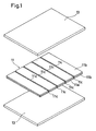
- Figs. 1 to 4 show an embodiment of the invention.
- Fig. 1 is a perspective view showing one positive electrode and separators which are to be placed on and below the electrode
- Fig. 2 is a perspective view showing the one positive electrode onto upper and lower surfaces of which the separators are fixed
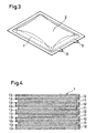
- Fig. 3 is a perspective view of a non-aqueous electrolyte secondary cell in which a power generating element is sealed by an aluminum laminate sheet
- Fig. 4 is a longitudinal section view showing the structure of the power generating element of the non-aqueous electrolyte secondary cell.
- a non-aqueous electrolyte secondary cell in which a power generating element 1 of the layer built type is sealed by covering it with an aluminum laminate sheet 2 as shown in Fig. 3 will be described.
- the power generating element 1 is configured by stacking positive electrodes 11, negative electrodes 12, and separators 13 which are plural and square.
- the positive and negative electrodes 11 and 12 are alternately arranged one by one, and the separators 13 are respectively interposed between the positive and negative electrodes 11 and 12.
- the positive electrodes 11 must be opposed to the corresponding negative electrodes 12.
- the positive electrodes 11 are formed so as to be slightly smaller in size than the negative electrodes 12, and the upper and lower end electrodes of the stacked structure are the negative electrodes 12.
- the separators 13 are formed so as to be equal in size to the negative electrodes 12, and disposed also above and below the negative electrodes 12 at the upper and lower ends of the stacked structure.
- the positive electrodes 11, the negative electrodes 12, and the separators 13 are fixed to one another at adjacent opposed faces so as to integrate the power generating element 1.
- the positive electrode 11 is a square thin plate in which a positive active material layer (positive mixture layer) 11b such as a lithium cobalt complex oxide is applied to upper and lower faces of a positive collector plate 11a configured by an electrically conductive metal plate or the like, and then dried so as to be carried thereon.
- a positive active material layer (positive mixture layer) 11b such as a lithium cobalt complex oxide
- the positive collector plate 11a configured by an electrically conductive metal plate or the like, and then dried so as to be carried thereon.
- plural linear grooves 11c which reaches both the edges of the square are formed in parallel and at equal intervals.
- the grooves 11c are formed by slightly denting the surfaces of the positive active material layers 11b.
- the positive active material layer 11b of a thickness of 140 ⁇ m is formed on each of the upper and lower faces of the positive collector plate 11a, and the layers are linearly roll-pressed from the upper and lower sides, thereby pressing the pressed portion to a thickness of about 100 ⁇ m.
- the grooves 11c of a depth of about 40 ⁇ m are formed at the same positions of the upper and lower faces.
- the grooves 11c may be formed by controlling the thickness during a process of applying the positive active material layers 11b.
- the grooves may be formed by previously forming dents in the positive collector plate.
- grooves 11c are not required to be linear as far as at least one end of each groove reaches an end portion of the positive electrode 11.
- grooves may be longitudinally and latitudinally formed in a lattice-like shape, or radially formed.
- the separator 13 is a square sheet of a microporous plastic film or the like. As described above, the separator is slightly larger in size than the positive electrode 11. As shown in Fig. 2, an adhesive agent such as PVDF is applied to the upper and lower faces of the positive electrode 11, and the separators are then bonded to the positive electrode, whereby the separators are fixed to the positive electrode.
- the negative electrode 12 shown in Fig. 4 is a square thin plate in which a negative active material mixture having a host material such as graphite that can intercalate and deintercalate lithium ions, and a binding agent is applied to an negative collector plate. Although not shown in Figs. 1 and 2, the separators 13 are similarly fixed to both the faces of the negative electrode 12, so that the positive electrodes 11 and the negative electrodes 12 are alternately stacked via the separators 13 as shown in Fig. 4.
- the power generating element 1 is covered by the aluminum laminate sheet 2 having barrier properties, and the periphery except a portion is first sealed.
- the sealing is surely conducted under the state where tip ends of leads 3 which are respectively connected to the positive and negative electrodes 11 and 12 of the power generating element 1 are protruded from gaps between the laminated aluminum laminate sheet 2.
- evacuation is conducted by, for example, placing the aluminum laminate sheet 2 in a chamber, whereby air is extracted from the interior of the power generating element 1.
- a non-aqueous electrolyte solution is poured into the aluminum laminate sheet 2.
- a preliminary charging process is performed via the leads 3, so that gas is generated between the electrodes 11 and 12.
- evacuation is again conducted so as to extract the gas.
- the aluminum laminate sheet 2 is then completely sealed to hermetically seal the interior, thereby completing the non-aqueous electrolyte secondary cell.
- the positive electrodes 11, the negative electrodes 12, and the separators 13 are fixed to one another to integrate the power generating element 1. Even when the power generating element 1 is not pressed by fastening with a tape or the like or housing in a cell container or the like, therefore, it is possible to eliminate a fear that the inter-electrode distance between the electrodes 11 and 12 is changed or the overlapping of the electrodes 11 and 12 and the separators 13 is misaligned. As a result, the power generating element can be housed in the flexible aluminum laminate sheet 2.
- non-aqueous electrolyte secondary cell of the embodiment a gas is generated between the positive and negative electrodes 11 and 12, only in an initial charging process. Consequently, a preliminary charging process must be performed before the aluminum laminate sheet 2 is completely sealed, so as to previously extract the gas.
- the non-aqueous electrolyte secondary cell may be housed in a card type outer case so as to be used as a secondary cell of the card type.
- the positive electrodes 11, the negative electrodes 12, and the separators 13 are shown so as to have a thickness which is larger than the actual one.
- the electrodes 11 and 12 and the separators 13 of the power generating element 1 are fixed to one another by the adhesive agent.
- the electrolyte solution cannot penetrate the interior of the power generating element 1 with passing between the electrodes 11 and 12 and the separators 13.
- a microporous plastic film or the like is used as the separators 13
- a non-aqueous electrolyte solution hardly penetrates into the separators as compared with the case of non-woven fabric or the like. Since the plural grooves 11c are formed in the positive electrodes 11, however, a non-aqueous electrolyte solution A shown in Fig.
- the diffusion rate of the non-aqueous electrolyte solution into the power generating element 1 is improved, and the gas extraction from the power generating element 1 can be rapidly performed. Consequently, the time for a work of pouring a non-aqueous electrolyte solution, and that of evacuation can be shortened, so that the productivity can be improved. Since the diffusion of a non-aqueous electrolyte solution, the gas extraction, and the drying of a solvent can be rapidly performed, the productivity is not lowered even when the electrodes 11 and 12 and the separators 13 are fixed to one another to integrate the power generating element 1. Consequently, the power generating element 1 can be housed in the flexible aluminum laminate sheet 2, so that the cell container can be made thin, light, and economical.
- the case where the positive electrodes 11, the negative electrodes 12, and the separators 13 are fixed to one another has been described. Even when these components are not fixed to one another, almost no gap is formed among them, and hence the formation of grooves in the electrodes enables the electrolyte solution to be rapidly dispersed.
- the case where the power generating element 1 is housed in the flexible aluminum laminate sheet 2 has been described.
- the container is not restricted to this.
- the power generating element may be housed in another flexible sheet-like cell container, or in a tough cell container configured by a metal can or the like.
- the grooves 11c are formed only in the positive electrode 11.
- the grooves may be formed also in the negative electrode 12.
- the grooves may be formed only in the negative electrode 12.
- the non-aqueous electrolyte secondary cell has been described. The invention is not restricted to this, and may be similarly executed also in a primary cell or another secondary cell.
- the configuration of the positive electrodes 11, the negative electrodes 12, and the separators 13 may be arbitrarily changed in accordance with the kind of the cell.
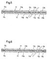
- Figs. 5 and 6 show Example 1 of the invention and are section views of electrodes which have undergone a grooving work
- Fig. 7 is a plan view of a groove pattern for a grooving work in Example 2.
- the positive active material layer (positive mixture layer) 11b having a predetermined thickness on one face is formed on each of the faces of the positive collector plate 11a configured by, for example, aluminum foil.
- the grooves 11c having a rectangular section shape are formed in the surface of the positive active material layer 11b, so as to be continuous in the surface of the positive active material layer 11b from one end portion of the electrode plate 11 to the opposed end portion.
- the positive active material layer was formed by applying and drying a mixture which was obtained by mixing 90 wt.% of a positive active material, 4 wt.% of acetylene black as a conductive agent, and 6 wt.% of PVDF as a binding agent, and making the mixture into a pasty state by adding an appropriate amount of N-methylpyrolidone as a solvent.
- LiCoO 2 was used as the positive active material.
- the thickness of the positive collector plate 11a was 20 ⁇ m
- the thickness of each positive active material layer 11b was 90 ⁇ m
- the width was 150 mm
- the length was 100 mm.
- the depth was 50 ⁇ m
- the width was 0.3 mm
- the center-to-center distance between the grooves was 5 mm.
- the negative electrode was formed by applying a mixture to both the faces of a negative collector configured by copper foil of 10 ⁇ m, and then drying the mixture.
- the mixture was obtained by mixing 94 wt.% of graphite, and 6 wt.% of PVDF as a binding agent, and making the mixture into a pasty state by adding an appropriate amount of N-methylpyrolidone as a solvent.
- the width was 160 mm, and the length was 110 mm.
- the separator is a microporous film of polyethylene and having a thickness of 25 ⁇ m, and 160 mm ⁇ 110 mm.
- the groove pattern of the grooves 11c in the surface of the electrode as shown in Fig. 7, many grooves 11c are formed so as to elongate in parallel.
- any working method including a mechanical working such as a die working, a press working, and a laser working may be employed.
- the grooves 11c were formed by a press working.
- the positive electrode, the separator 13 made of polyethylene, and the negative electrode were bonded together in this sequence by using PVDF (polyvinylidene fluoride) which was dissolved in NMP (N-methylpyrrolidone), as an adhesive agent.
- the electrode member consisting of the positive electrode 11, the separator 13, and the negative electrode was placed in a vacuum dryer which was set to a temperature of 80°C, and then evacuated.
- the timing when the electric resistance between the electrode plates reached 100 megaohms was used as an index of the end of the drying.
- the drying time for the electrode member in which the grooves 11c were formed was able to be shortened from 150 minutes to 30 minutes. As a result, the productivity of the cell production was remarkably improved.
- a cell was produced in the same configuration and procedure by using, as an adhesive agent, a mixture which was obtained by mixing into a solution of PVDF dissolved into NMP, 50 to 500 weight parts (with respect to PVDF) of alumina particles of a mean particle diameter of 0.01 ⁇ m per 100 weight parts of PVDF. Also the cell attained the same result.
- the alumina particles constitute a filler which forms a porous adhesive layer having a thickness of about 0.1 ⁇ m to 20 ⁇ m after drying.
- the alumina particles may be either of secondary particles or sintered particles.
- the particles are not restricted to alumina. For example, magnesium oxide, aluminum nitride, silicon dioxide, or the like may be used.
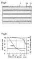
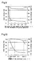
- Fig. 8 is a view showing relationships between the drying time of an electrode in production of a cell and the discharge capacity of a cell which was produced by using the electrode in the case where a positive active material layer (for example, LiCoO 2 was used as a positive active material) 11b having a predetermined thickness on one face was formed on each of the surfaces of the positive collector plate 11a and the widths of the grooves 11c formed in the surfaces of the positive active material layers 11b were changed.
- a positive active material layer for example, LiCoO 2 was used as a positive active material
- Example 2 the positive electrode 11 which was produced in Example 1 shown in Figs. 5 and 7 was used. Namely, as the positive electrode 11 an electrode was used in which the positive active material layer 11b having a thickness of 90 ⁇ m on one face was formed on both the faces of the positive collector plate 11a configured by aluminum foil and having a thickness of 20 ⁇ m, the width was 150 mm, and the length was 100 mm. For the positive electrode 11, the depth and the widths of the grooves were changed.
- the grooves 11c formed in the surfaces of the positive active material layers 11b were formed so as to be continuous from one end portion of the electrode 11 to the opposed end portion in the surfaces of the positive active material layers 11b. While changing the widths of the grooves 11c, the time period required for drying and the discharge capacity were measured. As described above, any working method including a mechanical working such as a die working, a press working, or a laser working may be employed as the method of forming the grooves 11c. In the example, a layer built cell was produced by using the positive electrode 11 in which the grooves 11c were formed by a press working. The negative electrode and the separator were the same as those of Example 1.
- an organic electrolyte solution an organic electrolyte solution of EC + DEC/1 : 1 and containing 1 mol/l of LiPF 6 was used.
- the positive collector plate 11a, the separator 13, and the negative electrode were bonded together by using PVDF (polyvinylidene fluoride) which was dissolved in NMP (N-methylpyrrolidone), as an adhesive agent.
- the positive electrode 11, the separator 13, and the negative electrode which were bonded together were placed in a vacuum dryer which was set to a temperature of 80°C, and then evacuated. The drying was ended at the timing when the electric resistance between the electrode plates reached 100 megaohms.
- Fig. 9 Results of studies on the effect of the depths of the grooves 11c with respect to the drying time in Example 2 are shown in Fig. 9. From Fig. 9, it was proved that a depth of 10 ⁇ m or more is effective in the drying time. Results of studies on the effect of the sectional areas of the grooves 11c with respect to the drying time are shown in Fig. 10.
- the sectional area is indicated as a ratio of the total area of the openings formed by the grooves 11c in a section which perpendicularly crosses the grooves 11c, to the sectional area of the active material layer. From Fig. 10, it was proved that the drying time is shorter as the sectional area is larger.
- relationships between the sectional areas of the grooves 11c and the cell properties were studied. As a result, it was revealed that the charge/discharge capacity is lower as the sectional area is larger.
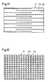
- the positive electrode 11 is used which was produced by forming the positive active material layer 11b having a thickness of 90 ⁇ m on one face, on both the faces of the positive collector plate 11a configured by aluminum foil of a thickness of 20 ⁇ m, a width of 150 mm, a length of 100 mm, and the rectangular grooves 11c of a depth of 50 ⁇ m, and a width of 0.3 mm so as to be linear and continuous from one end portion of the electrode 11 to the opposed end portion in the surfaces of the positive active material layers 11b. As shown in Fig. 11, among the groove groups 11c, 11c, ...
- grooves adjacent to each other were formed so that the grooves reach only one of opposed end portions of the electrode and the opposite sides of the grooves are stopped halfway so as not to reach the end portions of the electrode.
- Plural grooves 11c are formed so that the center-to-center distance between the grooves in the surface of the electrode is 10 mm.
- any working method including a mechanical working such as a die working, a press working, and a laser working may be employed.
- a layer built cell was produced by using the electrode 11 in which the grooves 11c were formed by a press working.
- the positive electrode 11, the separator 13, and the negative electrode were bonded together by using PVDF (polyvinylidene fluoride) which was dissolved in NMP (N-methylpyrrolidone), as an adhesive agent.
- PVDF polyvinylidene fluoride
- NMP N-methylpyrrolidone
- the positive electrode 11, the separator 13, and the negative electrode which were bonded together was placed in a vacuum dryer which was set to a temperature of 80°C, and then evacuated. The drying was ended at the timing when the electric resistance between the electrode plates reached 100 megaohms.
- the materials and the like of the positive electrode, the negative electrode, the separator, and the cell were the same as those of Example 1.
- Example 3 the electrode 11 in which the grooves are alternately connected to the end portions of the electrode, and the electrode 11 in which all grooves are connected to the end portions of the electrode were compared with each other with respect to drying time.
- the drying time of the latter electrode 11 in which all grooves are connected to the end portions of the electrode was shorter than that of the former electrode.
- the groove working method for the latter electrode 11 was superior.
- the mechanical strength of the positive electrode 11 such as the bending strength, however, the former is superior to the latter, and the handling of the electrode can be improved.
- the productivity of the cell production was improved.
- the positive electrode 11 is used which was produced by forming the positive active material layer 11b having a thickness of 90 ⁇ m on one face, on both the faces of the positive collector plate 11a configured by aluminum foil of a thickness of 20 ⁇ m, and the rectangular grooves 11c of a width of 150 mm, a length of 100 mm, a depth of 50 ⁇ m, and a width of 0.3 mm so as to be linear and continuous from one end portion of the electrode 11 to the opposed end portion in the surfaces of the positive active material layers 11b.
- Plural grooves 11c are formed so that the center-to-center distance between the grooves in the surface of the electrode is 5 mm.
- the positive active material layer 11b having a thickness of 90 ⁇ m on one face, on both the faces of the positive collector plate 11a configured by aluminum foil of a thickness of 20 ⁇ m
- the rectangular grooves 11c of a width of 150 mm, a length of 100 mm, a depth of 50 ⁇ m, and a width of 0.3 mm
- the grooves 11c were formed so that a series of groove groups perpendicularly cross one other. Therefore, the groove groups 11c constitute lattice-like grooves on the surface of the electrode.
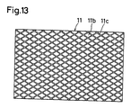
- the grooves 11c are not required to have a pattern in which grooves in two directions perpendicularly cross one other, and may have a pattern such as shown in Fig. 13.
- the pattern of Fig. 13 in which no grooves 11c that are close to an angle of 90 degrees with respect to the winding direction of the cell are formed is superior from the view point in that the electrode is prevented from being cut from the groove 11c during the winding process.
- any working method including a mechanical working such as a die working, a press working, and a laser working may be employed.
- a press working a pressing operation may be conducted plural times for grooves of different directions.
- a die roll in which the shape of grooves to be formed is engraved is previously formed, and the grooves may be formed by a single pressing operation.
- Example 4 a layer built cell was produced in the same manner as Example 1 by using the positive electrode 11 in which grooves were formed by a press working.
- the positive electrode 11, the separators 13, and the negative electrode were bonded together by using PVDF (polyvinylidene fluoride) which was dissolved in NMP (N-methylpyrrolidone), as an adhesive agent.
- PVDF polyvinylidene fluoride
- NMP N-methylpyrrolidone
- Example 4 As compared with an electrode member in which no grooves were formed, the drying time for the electrode member in which the grooves 11c were formed was able to be shortened from 150 minutes to 25 minutes. As a result, the productivity of the cell production was remarkably improved.
- the configurations, materials, and the like of the positive electrode, the negative electrode, the separator, and the cell were the same as those of Example 1.
- the positive electrode 11 is used which was produced by forming the positive active material layer 11b having a thickness of 90 ⁇ m on one face, on both the faces of the positive collector plate 11a configured by aluminum foil of a thickness of 20 ⁇ m, and the rectangular grooves 11c of a width of 150 mm, a length of 100 mm, a depth of 50 ⁇ m, and a width of 0.3 mm so as to be linear and continuous from one end portion of the electrode 11 to the opposed end portion in the surfaces of the positive active material layers 11b.
- Plural grooves 11c are formed so that the center-to-center distance between the grooves in the surface of the electrode is 10 mm.
- the groove shape was formed so that the groove width is gradually increased as moving from the center portion of the electrode toward an end portion of the electrode.
- the positive electrode 11 was produced in which the groove shape was formed so that the depth is gradually increased as moving from the center portion of the electrode toward an end portion of the electrode.
- any working method including a mechanical working may be employed.
- Example 5 a layer built cell was produced in the same manner as Example 1 by using the positive electrode 11 in which grooves were formed by a press working. In this case, the positive electrode 11, the separators 13, and the negative electrode were bonded together by using PVDF (polyvinylidene fluoride) which was dissolved in NMP (N-methylpyrrolidone), as an adhesive agent.
- the positive electrode 11, the separator 13, the negative electrode 12, and the like which were bonded together were placed in a vacuum dryer which was set to a temperature of 80°C, and then evacuated. The drying was ended at the timing when the electric resistance between the electrode plates reached 100 megaohms.
- Example 5 As compared with an electrode member in which the groove width or the depth in the electrode surface is not changed, the drying time for the electrode member in which both the groove width and the depth in the electrode surface become larger as moving toward the end of the electrode was able to be shortened from 35 minutes to 28 minutes. As a result, the productivity of the cell production was improved.
- the configurations, materials, and the like of the positive electrode, the negative electrode, the separator, and the cell were the same as those of Example 1.
- the positive electrode 11 is used which was produced by forming the positive active material layer 11b having a thickness of 90 ⁇ m on one face, on both the faces of the positive collector plate 11a configured by aluminum foil of a thickness of 20 ⁇ m, and the rectangular grooves 11c of a width of 150 mm, a length of 100 mm, a depth of 50 ⁇ m, and a width of 0.3 mm so as to be linear and continuous from one end portion of the electrode plate 11 to the opposed end portion in the surface of the positive active material 11b.
- Plural grooves 11c are formed so that the center-to-center distance between the grooves in the surface of the electrode is 5 mm.
- any working method including a mechanical working such as a die working, a press working, and a laser working may be employed.
- a linear projection pattern was produced in a stainless steel die roll having a diameter of 400 mm and a length of 400 mm, by an engraving method.
- the projection pattern was set to have a pitch of 5 mm, a width of 0.3 mm, and a depth of 0.05 mm.
- Two rolls which had undergone the working of the projection pattern were prepared.
- the positive electrode 11 in which the positive active material 11b was formed on both the faces of the positive collector plate 11a was passed between the two rolls, whereby the grooves 11c were simultaneously formed in both the faces of the active material layer.
- a layer built cell was produced in the same manner as Example 1 by using the positive electrode 11 in which the grooves 11c were formed by a groove working using the rolls.
- the positive electrode 11, the separators 13, and the negative electrode were bonded together by using PVDF (polyvinylidene fluoride) which was dissolved in NMP (N-methylpyrrolidone), as an adhesive agent.
- PVDF polyvinylidene fluoride
- NMP N-methylpyrrolidone
- the positive electrode 11 and the separator 13 which were bonded together were placed in a vacuum dryer which was set to a temperature of 80°C, and then evacuated. The drying was ended at the timing when the electric resistance between the electrode plates reached 100 megaohms. It is suitable to apply a pressure of 25 to 250 kgf/cm (per the width of the electrode).
- Example 6 As compared with an electrode member in which the groove width or the depth in the electrode surface is not changed, the drying time was able to be shortened from 150 minutes to 30 minutes. As a result, the productivity of the cell production was improved.
- the configurations, materials, and the like of the positive electrode, the negative electrode, the separator, and the cell were the same as those of Example 1.
- Example 7 a cell was produced while groove working was conducted in the same manner as Example 6 except that only the depths of the projection pattern of the rolls were set to be 0.1 mm. As compared with the case of the groove depth of 0.05 mm, the depths of the grooves which were actually formed in the electrode were not largely changed. In the case of the groove width of 0.1 mm, however, the electrode in which grooves were formed had no flatness and was bent at a portion of the groove 11c. Therefore, it is seemed that the bending can be suppressed by reducing the groove depth of the rolls so as to allow the portions of the rolls other than the projections to abut against the electrode.
- the invention can be similarly executed also in a power generating element of another structure, such as that of the wound type.
- a poured electrolyte solution rapidly penetrates the interior of the power generating element along the groove of the electrode. Therefore, the diffusion rate of an electrolyte solution can be improved. Also when the electrode is fixed to the separator and the power generating element is integrated, the diffusion of an electrolyte solution and the gas extraction are prevented from being impaired.
- This integration of the power generating element enables a flexible sheet-like cell container to be used. Therefore, a reduced thickness, a small size, and a light weight of a cell can be realized, and the invention can contribute to a reduced production cost. Since a solvent of the adhesive agent layer can be rapidly evaporated, the drying time is shortened and hence it is possible to obtain a cell of excellent productivity. Even when the groove has a shape in which the groove bottom portion has a flat portion, furthermore, the drying time can be shortened. More preferably, the length of the flat portion is at least 10% of the groove depth.
Landscapes
- Chemical & Material Sciences (AREA)
- Engineering & Computer Science (AREA)
- Manufacturing & Machinery (AREA)
- Chemical Kinetics & Catalysis (AREA)
- Electrochemistry (AREA)
- General Chemical & Material Sciences (AREA)
- Dispersion Chemistry (AREA)
- Secondary Cells (AREA)
- Battery Electrode And Active Subsutance (AREA)
- Primary Cells (AREA)
Claims (10)
- Stromerzeugungselement, bei welchem eine oder mehrere positive Elektroden und eine oder mehrere Elektrolyt-durchdringbare negative Elektroden über eine Elektrolytrückhalteschicht abwechselnd nahe beieinanderliegend angeordnet sind,
wobei eine Nut in einer Fläche ausgebildet ist, welche eine Oberfläche von mindestens einer der Elektroden ist, wobei die Fläche der anderen Elektrode über eine Elektrolytrückhalteschicht gegenüberliegt, mindestens ein Ende der Nut bis zu einem Ende der Elektrode reicht, und die Elektrolytrückhalteschicht ein mikroporöser Kunststofffilm ist. - Stromerzeugungselement nach Anspruch 1,
bei welchem die Elektrolytrückhalteschicht ein Separator ist. - Stromerzeugungselement nach Anspruch 1,
bei welchem die Nut einen Abschnitt von einer Tiefe von 10 µm oder mehr hat. - Stromerzeugungselement nach Anspruch 1,
bei welchem die Querschnittsfläche der ausgebildeten Nut nicht weniger als 0,2 % und nicht mehr als 10 % der Gesamtquerschnittsfläche einer Mischungsschicht beträgt, in welcher die Nut ausgebildet ist. - Stromerzeugungselement nach Anspruch 1,
bei welchem die ausgebildete Nut linear ist. - Stromerzeugungselement nach Anspruch 1,
bei welchem die in der Elektrode ausgebildete Nut durch mindestens zwei Nutgruppen von einer Nutgruppe, die aus einer Reihe von Nuten besteht, welche in einer Elektrodenfläche in einer einzigen Richtung ausgerichtet sind, und aus einer Nutgruppe konfiguriert ist, die aus einer Reihe von Nuten besteht, welche in einer sich von der zuvor erwähnten Richtung unterscheidenden Richtung ausgerichtet sind. - Zelle, die das Stromerzeugungselement nach einem der Ansprüche 1 bis 6 aufweist.
- Zelle nach Anspruch 7,
bei welcher mindestens eine der Grenzflächen, die jeweils durch zwei von der positiven Elektrode, der negativen Elektrode und der Elektrolytrückhalteschicht gebildet sind, durch eine feine Partikel enthaltende Klebstoffschicht verklebt ist. - Zelle nach Anspruch 7,
bei welcher die positiven und negativen Elektroden durch die zwischen die Elektroden eingelegte Elektrolytrückhalteschicht befestigt sind. - Zelle nach Anspruch 7 oder 8, bei welcher
das Stromerzeugungselement in einem Zellenbehälter untergebracht ist, bei welchem eine übereinander geschichtete Lage aus Metall und Kunstharz ein Bestandteil ist.
Applications Claiming Priority (3)
| Application Number | Priority Date | Filing Date | Title |
|---|---|---|---|
| JP10505197 | 1997-04-23 | ||
| JP10505197 | 1997-04-23 | ||
| PCT/JP1998/001844 WO1998048466A1 (fr) | 1997-04-23 | 1998-04-22 | Electrode et batterie |
Publications (3)
| Publication Number | Publication Date |
|---|---|
| EP0967672A1 EP0967672A1 (de) | 1999-12-29 |
| EP0967672A4 EP0967672A4 (de) | 2003-01-22 |
| EP0967672B1 true EP0967672B1 (de) | 2005-06-29 |
Family
ID=14397198
Family Applications (1)
| Application Number | Title | Priority Date | Filing Date |
|---|---|---|---|
| EP98917623A Expired - Lifetime EP0967672B1 (de) | 1997-04-23 | 1998-04-22 | Elektrode und batterie |
Country Status (5)
| Country | Link |
|---|---|
| EP (1) | EP0967672B1 (de) |
| CN (1) | CN1192445C (de) |
| AT (1) | ATE298932T1 (de) |
| DE (1) | DE69830712T2 (de) |
| WO (1) | WO1998048466A1 (de) |
Families Citing this family (55)
| Publication number | Priority date | Publication date | Assignee | Title |
|---|---|---|---|---|
| JP4149543B2 (ja) * | 1997-11-19 | 2008-09-10 | 株式会社東芝 | 非水電解液電池 |
| JP2000195525A (ja) * | 1998-12-28 | 2000-07-14 | Sanyo Electric Co Ltd | 非水電解液電池 |
| JP2001176558A (ja) * | 1999-12-20 | 2001-06-29 | Toshiba Corp | 非水電解液二次電池 |
| JP4565713B2 (ja) * | 2000-08-04 | 2010-10-20 | トータル ワイヤレス ソリューショオンズ リミテッド | シート状リチウム電池構造及びシート状リチウム電池の製造方法 |
| WO2002043168A2 (en) * | 2000-10-20 | 2002-05-30 | Massachusetts Institute Of Technology | Reticulated and controlled porosity battery structures |
| EP1300897A1 (de) * | 2001-10-02 | 2003-04-09 | Francois Sugnaux | Segmentierte mesoporöse keramische Elektroden für elektrochemische Vorrichtungen und daraus hergestellte Vorrichtungen |
| JP2003187875A (ja) * | 2001-12-18 | 2003-07-04 | Japan Storage Battery Co Ltd | 非水電解質二次電池 |
| JP4179778B2 (ja) * | 2001-12-27 | 2008-11-12 | 三洋電機株式会社 | 非水電解液電池 |
| JP4454948B2 (ja) | 2002-04-12 | 2010-04-21 | 株式会社東芝 | 非水電解液二次電池 |
| CN100424917C (zh) * | 2004-05-25 | 2008-10-08 | 松下电器产业株式会社 | 锂离子二次电池及其制造方法 |
| JP4657001B2 (ja) * | 2004-05-25 | 2011-03-23 | パナソニック株式会社 | リチウムイオン二次電池およびその製造方法 |
| JP2006202680A (ja) * | 2005-01-24 | 2006-08-03 | Nissan Motor Co Ltd | ポリマー電池 |
| CN101132066B (zh) * | 2006-08-25 | 2011-01-12 | 比亚迪股份有限公司 | 锌负极和包括该负极的二次锌镍电池及它们的制备方法 |
| CN101517816A (zh) | 2006-10-30 | 2009-08-26 | 松下电器产业株式会社 | 二次电池及其制造方法 |
| JP5401756B2 (ja) * | 2006-11-28 | 2014-01-29 | 日産自動車株式会社 | 二次電池 |
| DE102006062407A1 (de) * | 2006-12-20 | 2008-06-26 | Varta Microbattery Gmbh | Galvanisches Element mit einem geklebten Verbund aus Elektroden und Separator |
| US20080248386A1 (en) * | 2007-04-05 | 2008-10-09 | Obrovac Mark N | Electrodes with raised patterns |
| US20090202903A1 (en) | 2007-05-25 | 2009-08-13 | Massachusetts Institute Of Technology | Batteries and electrodes for use thereof |
| EP2001073B1 (de) | 2007-06-06 | 2012-02-22 | Nissan Motor Co., Ltd. | Sekundärbatterie und Verfahren zur Herstellung einer Sekundärbatterie |
| CN101662011B (zh) * | 2008-08-26 | 2013-05-29 | 比亚迪股份有限公司 | 一种电池极片及其制备方法和含有该极片的电池 |
| JP5547556B2 (ja) | 2010-06-08 | 2014-07-16 | 大日本スクリーン製造株式会社 | 電池、車両、電子機器および電池の製造方法 |
| CN102255073A (zh) * | 2010-11-04 | 2011-11-23 | 耿世达 | 一种增强锂离子电池正负极极片结构的新工艺 |
| US9065093B2 (en) | 2011-04-07 | 2015-06-23 | Massachusetts Institute Of Technology | Controlled porosity in electrodes |
| US9337462B2 (en) * | 2011-04-14 | 2016-05-10 | Karlsruher Institut Fur Technologie (Kit) | Electrolyte batteries |
| CN102306746A (zh) * | 2011-09-09 | 2012-01-04 | 东莞新能源科技有限公司 | 锂离子电池阴极极片及其制备方法 |
| JP5392328B2 (ja) * | 2011-09-12 | 2014-01-22 | 日産自動車株式会社 | 固体電解質電池 |
| JP5844659B2 (ja) * | 2012-02-27 | 2016-01-20 | 京セラ株式会社 | 電極板およびそれを用いた二次電池 |
| JP5621824B2 (ja) * | 2012-10-02 | 2014-11-12 | 日産自動車株式会社 | 電池用電極およびその製造方法 |
| CN103094521A (zh) * | 2013-01-22 | 2013-05-08 | 宁德时代新能源科技有限公司 | 锂离子动力电池正极片及其制造方法、激光蚀刻装置 |
| JP2015053204A (ja) * | 2013-09-09 | 2015-03-19 | トヨタ自動車株式会社 | 電極製造装置および電極製造方法 |
| CN104124428A (zh) * | 2014-08-12 | 2014-10-29 | 宁波星锐能源科技有限公司 | 一种卷绕式锂锰电池正极片 |
| US10675819B2 (en) | 2014-10-03 | 2020-06-09 | Massachusetts Institute Of Technology | Magnetic field alignment of emulsions to produce porous articles |
| US10569480B2 (en) | 2014-10-03 | 2020-02-25 | Massachusetts Institute Of Technology | Pore orientation using magnetic fields |
| CN107004831B (zh) * | 2014-11-28 | 2020-10-02 | 三洋电机株式会社 | 非水电解质二次电池用正极和非水电解质二次电池 |
| CN105428595A (zh) * | 2016-01-11 | 2016-03-23 | 深圳市沃特玛电池有限公司 | 一种锂离子电池及其制备方法 |
| DE102016218495A1 (de) * | 2016-09-27 | 2018-03-29 | Robert Bosch Gmbh | Verfahren zur Herstellung eines Elektrodenstapels für eine Batteriezelle und Batteriezelle |
| CN107068980A (zh) * | 2017-06-02 | 2017-08-18 | 中天储能科技有限公司 | 一种阶梯型电池极片及其专用压辊 |
| WO2019079652A1 (en) * | 2017-10-19 | 2019-04-25 | Sila Nanotechnologies, Inc. | LI-ION BATTERY ELEMENT ANODE ELECTRODE COMPOSITION |
| JP2020017398A (ja) * | 2018-07-25 | 2020-01-30 | 積水化学工業株式会社 | 蓄電素子 |
| CN109768223A (zh) * | 2019-03-15 | 2019-05-17 | 湖北锂诺新能源科技有限公司 | 一种卷绕式锂离子电池负极极片的制备方法 |
| US12107276B2 (en) * | 2019-09-24 | 2024-10-01 | Lg Energy Solution, Ltd. | Positive electrode for lithium-sulfur secondary battery having pattern, manufacturing method therefor, and lithium-sulfur secondary battery including same |
| JP7569801B2 (ja) * | 2019-11-29 | 2024-10-18 | 三洋電機株式会社 | 非水電解質二次電池、及び非水電解質二次電池の製造方法 |
| CN112563443B (zh) * | 2020-11-20 | 2022-08-12 | 扬州大学 | 一种柔性电池电极及其制作工艺 |
| CN112467073A (zh) * | 2020-12-21 | 2021-03-09 | 江苏双登富朗特新能源有限公司 | 一种锂离子电池极片及其制备方法 |
| CN112750979A (zh) * | 2021-01-29 | 2021-05-04 | 天津市捷威动力工业有限公司 | 一种锂离子电池沟渠型极片及其制备方法 |
| JP7385610B2 (ja) | 2021-02-17 | 2023-11-22 | プライムプラネットエナジー&ソリューションズ株式会社 | 二次電池の製造方法 |
| JP7229289B2 (ja) | 2021-03-12 | 2023-02-27 | プライムプラネットエナジー&ソリューションズ株式会社 | 二次電池用電極の製造方法 |
| JP7320010B2 (ja) * | 2021-03-12 | 2023-08-02 | プライムプラネットエナジー&ソリューションズ株式会社 | 二次電池用電極の製造方法および電極ならびに該電極を備える二次電池 |
| WO2023027539A1 (ko) * | 2021-08-26 | 2023-03-02 | 주식회사 엘지에너지솔루션 | 전극 및 전극의 제조방법 |
| JP7528898B2 (ja) * | 2021-09-21 | 2024-08-06 | トヨタ自動車株式会社 | 二次電池用電極および二次電池 |
| CN114203970B (zh) * | 2021-11-30 | 2024-04-19 | 华中科技大学 | 一种改善锂电池电解液浸润性的电极极片及其制备方法 |
| JP2023101951A (ja) * | 2022-01-11 | 2023-07-24 | トヨタ自動車株式会社 | 電極の製造方法、電極集電体および電極 |
| DE102022106343A1 (de) | 2022-03-18 | 2023-09-21 | Audi Aktiengesellschaft | Energiespeicheranordnung für ein Kraftfahrzeug und Verfahren zum Herstellen einer Energiespeicheranordnung |
| KR20250008944A (ko) * | 2022-05-23 | 2025-01-16 | 가부시키가이샤 도요다 지도숏키 | 리튬 이온 이차 전지용의 전극 및 리튬 이온 이차 전지 |
| WO2024262490A1 (ja) * | 2023-06-22 | 2024-12-26 | パナソニックIpマネジメント株式会社 | 円筒形電池及びその製造方法 |
Family Cites Families (8)
| Publication number | Priority date | Publication date | Assignee | Title |
|---|---|---|---|---|
| JP3509031B2 (ja) * | 1993-12-10 | 2004-03-22 | 片山特殊工業株式会社 | リード付き金属多孔体の製造方法及び該方法により製造されたリード付き金属多孔体 |
| JPH07272760A (ja) * | 1994-03-29 | 1995-10-20 | Shin Kobe Electric Mach Co Ltd | リチウム二次電池 |
| JPH07320788A (ja) * | 1994-05-18 | 1995-12-08 | Hitachi Maxell Ltd | リチウム二次電池およびその製造方法 |
| JP3300168B2 (ja) * | 1994-09-22 | 2002-07-08 | 松下電器産業株式会社 | 非水電解質二次電池用負極、その製造方法および非水電解質二次電池 |
| JPH08153515A (ja) * | 1994-11-28 | 1996-06-11 | Toyota Autom Loom Works Ltd | 渦巻き型電池の電極 |
| JPH09298057A (ja) * | 1996-04-30 | 1997-11-18 | Sanyo Electric Co Ltd | リチウムイオン電池 |
| JPH09330704A (ja) * | 1996-06-12 | 1997-12-22 | Shin Kobe Electric Mach Co Ltd | 電池用極板の製造法 |
| JP3303694B2 (ja) * | 1996-12-17 | 2002-07-22 | 三菱電機株式会社 | リチウムイオン二次電池及びその製造方法 |
-
1998
- 1998-04-22 WO PCT/JP1998/001844 patent/WO1998048466A1/ja not_active Ceased
- 1998-04-22 EP EP98917623A patent/EP0967672B1/de not_active Expired - Lifetime
- 1998-04-22 AT AT98917623T patent/ATE298932T1/de not_active IP Right Cessation
- 1998-04-22 CN CNB98812971XA patent/CN1192445C/zh not_active Expired - Fee Related
- 1998-04-22 DE DE69830712T patent/DE69830712T2/de not_active Expired - Fee Related
Also Published As
| Publication number | Publication date |
|---|---|
| EP0967672A4 (de) | 2003-01-22 |
| DE69830712D1 (de) | 2005-08-04 |
| ATE298932T1 (de) | 2005-07-15 |
| CN1285959A (zh) | 2001-02-28 |
| EP0967672A1 (de) | 1999-12-29 |
| CN1192445C (zh) | 2005-03-09 |
| DE69830712T2 (de) | 2005-12-15 |
| WO1998048466A1 (fr) | 1998-10-29 |
Similar Documents
| Publication | Publication Date | Title |
|---|---|---|
| EP0967672B1 (de) | Elektrode und batterie | |
| JP3745594B2 (ja) | 電池及びこの電池の電極成形装置 | |
| JP3745593B2 (ja) | 電池およびその製造方法 | |
| US7820337B2 (en) | Electrochemical device | |
| KR100430123B1 (ko) | 비수전해질전지 및 그 제조법 | |
| KR100731240B1 (ko) | 비수계 겔 전해질 전지의 제조 방법 | |
| EP2966721A1 (de) | Sekundärbatterie mit wasserfreiem elektrolyt | |
| US20050244716A1 (en) | Lithium-ion secondary battery and method of charging lithium-ion secondary battery | |
| EP1128450A2 (de) | Elektrodenverbindung für Batterien und Herstellungsverfahren | |
| US20210305630A1 (en) | Positive electrode for solid-state battery, manufacturing method for positive electrode for solid-state battery, and solid-state battery | |
| KR20030074645A (ko) | 비수전해질 이차전지, 그 제조법 및 전지집합체 | |
| KR100547085B1 (ko) | 고분자 다공성 분리막 및 리튬이온 고분자 전지의 제조방법 | |
| JPWO2000013252A1 (ja) | 非水系ゲル電解質電池の製造方法 | |
| KR20080007143A (ko) | 전지 전극, 리튬 이온 2차 배터리, 리튬 이온 2차 배터리를 포함하는 집합 배터리 및 차량 | |
| JP2004207253A (ja) | 非水電解質二次電池 | |
| KR19980079730A (ko) | 적층 리튬이온 전지와 그 제조방법 | |
| KR101182892B1 (ko) | 극판과 그 제조방법 및 이 극판을 포함한 이차전지 | |
| KR20160056553A (ko) | 요철 형상의 전극 합제가 코팅된 전극 | |
| EP1132988A2 (de) | Festelektrolytbatterie und Verfahren zur Herstellung | |
| JP2001229971A (ja) | 非水電解液二次電池 | |
| WO2008026358A1 (en) | Electrode for nonaqueous electrolyte secondary battery, process for producing the same, and nonaqueous electrolyte secondary battery | |
| CN114868295A (zh) | 非水电解质二次电池及其制造方法 | |
| US20230246246A1 (en) | Wound electrode assembly, battery, and manufacturing method of wound electrode assembly | |
| US6833009B2 (en) | Method of fabrication of composite electrodes in lithium ion battery and cells | |
| US6737196B2 (en) | Method of making a lithium polymer battery and battery made by the method |
Legal Events
| Date | Code | Title | Description |
|---|---|---|---|
| PUAI | Public reference made under article 153(3) epc to a published international application that has entered the european phase |
Free format text: ORIGINAL CODE: 0009012 |
|
| 17P | Request for examination filed |
Effective date: 19991020 |
|
| AK | Designated contracting states |
Kind code of ref document: A1 Designated state(s): AT BE CH CY DE DK ES FI FR GB GR IE IT LI LU MC NL PT SE |
|
| A4 | Supplementary search report drawn up and despatched |
Effective date: 20021205 |
|
| AK | Designated contracting states |
Kind code of ref document: A4 Designated state(s): AT BE CH CY DE DK ES FI FR GB GR IE IT LI LU MC NL PT SE |
|
| 17Q | First examination report despatched |
Effective date: 20030526 |
|
| GRAP | Despatch of communication of intention to grant a patent |
Free format text: ORIGINAL CODE: EPIDOSNIGR1 |
|
| GRAS | Grant fee paid |
Free format text: ORIGINAL CODE: EPIDOSNIGR3 |
|
| RIN1 | Information on inventor provided before grant (corrected) |
Inventor name: KISE, MAKIKO-MITSUBISHI DENKI KABUSHIKI KAISHA Inventor name: YOSHIOKA, SHOJI-MITSUBISHI DENKI KABUSHIKI KAISHA Inventor name: ARAGANE, JUN-MITSUBISHI DENKI KABUSHIKI KAISHA Inventor name: URUSHIBATA, HIROAKI-MITSUBISHI DENKI KABUSHIKI K. Inventor name: SHIOTA, HISASHI-MITSUBISHI DENKI KABUSHIKI KAISHA Inventor name: TAKEMURA, DAIGO-MITSUBISHI DENKI KABUSHIKI KAISHA Inventor name: AIHARA, SHIGERU-MITSUBISHI DENKI KABUSHIKI KAISHA Inventor name: TSUKAMOTO, HISASHI-JAPAN STORAGE BATTERY CO., LTD. Inventor name: ARIMA, YOICHIRO-JAPAN STORAGE BATTERY CO., LTD. |
|
| GRAA | (expected) grant |
Free format text: ORIGINAL CODE: 0009210 |
|
| AK | Designated contracting states |
Kind code of ref document: B1 Designated state(s): AT BE CH CY DE DK ES FI FR GB GR IE IT LI LU MC NL PT SE |
|
| PG25 | Lapsed in a contracting state [announced via postgrant information from national office to epo] |
Ref country code: NL Free format text: LAPSE BECAUSE OF FAILURE TO SUBMIT A TRANSLATION OF THE DESCRIPTION OR TO PAY THE FEE WITHIN THE PRESCRIBED TIME-LIMIT Effective date: 20050629 Ref country code: LI Free format text: LAPSE BECAUSE OF FAILURE TO SUBMIT A TRANSLATION OF THE DESCRIPTION OR TO PAY THE FEE WITHIN THE PRESCRIBED TIME-LIMIT Effective date: 20050629 Ref country code: IT Free format text: LAPSE BECAUSE OF FAILURE TO SUBMIT A TRANSLATION OF THE DESCRIPTION OR TO PAY THE FEE WITHIN THE PRESCRIBED TIME-LIMIT;WARNING: LAPSES OF ITALIAN PATENTS WITH EFFECTIVE DATE BEFORE 2007 MAY HAVE OCCURRED AT ANY TIME BEFORE 2007. THE CORRECT EFFECTIVE DATE MAY BE DIFFERENT FROM THE ONE RECORDED. Effective date: 20050629 Ref country code: FI Free format text: LAPSE BECAUSE OF FAILURE TO SUBMIT A TRANSLATION OF THE DESCRIPTION OR TO PAY THE FEE WITHIN THE PRESCRIBED TIME-LIMIT Effective date: 20050629 Ref country code: CH Free format text: LAPSE BECAUSE OF FAILURE TO SUBMIT A TRANSLATION OF THE DESCRIPTION OR TO PAY THE FEE WITHIN THE PRESCRIBED TIME-LIMIT Effective date: 20050629 Ref country code: BE Free format text: LAPSE BECAUSE OF FAILURE TO SUBMIT A TRANSLATION OF THE DESCRIPTION OR TO PAY THE FEE WITHIN THE PRESCRIBED TIME-LIMIT Effective date: 20050629 Ref country code: AT Free format text: LAPSE BECAUSE OF FAILURE TO SUBMIT A TRANSLATION OF THE DESCRIPTION OR TO PAY THE FEE WITHIN THE PRESCRIBED TIME-LIMIT Effective date: 20050629 |
|
| REG | Reference to a national code |
Ref country code: GB Ref legal event code: FG4D |
|
| REG | Reference to a national code |
Ref country code: CH Ref legal event code: EP |
|
| REF | Corresponds to: |
Ref document number: 69830712 Country of ref document: DE Date of ref document: 20050804 Kind code of ref document: P |
|
| REG | Reference to a national code |
Ref country code: IE Ref legal event code: FG4D |
|
| PG25 | Lapsed in a contracting state [announced via postgrant information from national office to epo] |
Ref country code: SE Free format text: LAPSE BECAUSE OF FAILURE TO SUBMIT A TRANSLATION OF THE DESCRIPTION OR TO PAY THE FEE WITHIN THE PRESCRIBED TIME-LIMIT Effective date: 20050929 Ref country code: GR Free format text: LAPSE BECAUSE OF FAILURE TO SUBMIT A TRANSLATION OF THE DESCRIPTION OR TO PAY THE FEE WITHIN THE PRESCRIBED TIME-LIMIT Effective date: 20050929 Ref country code: DK Free format text: LAPSE BECAUSE OF FAILURE TO SUBMIT A TRANSLATION OF THE DESCRIPTION OR TO PAY THE FEE WITHIN THE PRESCRIBED TIME-LIMIT Effective date: 20050929 |
|
| PG25 | Lapsed in a contracting state [announced via postgrant information from national office to epo] |
Ref country code: ES Free format text: LAPSE BECAUSE OF FAILURE TO SUBMIT A TRANSLATION OF THE DESCRIPTION OR TO PAY THE FEE WITHIN THE PRESCRIBED TIME-LIMIT Effective date: 20051010 |
|
| NLV1 | Nl: lapsed or annulled due to failure to fulfill the requirements of art. 29p and 29m of the patents act | ||
| PG25 | Lapsed in a contracting state [announced via postgrant information from national office to epo] |
Ref country code: PT Free format text: LAPSE BECAUSE OF FAILURE TO SUBMIT A TRANSLATION OF THE DESCRIPTION OR TO PAY THE FEE WITHIN THE PRESCRIBED TIME-LIMIT Effective date: 20051207 |
|
| REG | Reference to a national code |
Ref country code: CH Ref legal event code: PL |
|
| ET | Fr: translation filed | ||
| PGFP | Annual fee paid to national office [announced via postgrant information from national office to epo] |
Ref country code: FR Payment date: 20060420 Year of fee payment: 9 |
|
| PG25 | Lapsed in a contracting state [announced via postgrant information from national office to epo] |
Ref country code: IE Free format text: LAPSE BECAUSE OF NON-PAYMENT OF DUE FEES Effective date: 20060424 |
|
| PGFP | Annual fee paid to national office [announced via postgrant information from national office to epo] |
Ref country code: GB Payment date: 20060426 Year of fee payment: 9 |
|
| REG | Reference to a national code |
Ref country code: FR Ref legal event code: CD |
|
| PG25 | Lapsed in a contracting state [announced via postgrant information from national office to epo] |
Ref country code: MC Free format text: LAPSE BECAUSE OF NON-PAYMENT OF DUE FEES Effective date: 20060430 |
|
| RAP2 | Party data changed (patent owner data changed or rights of a patent transferred) |
Owner name: MITSUBISHI DENKI KABUSHIKI KAISHA Owner name: JAPAN STORAGE BATTERY CO., LTD. |
|
| PLBE | No opposition filed within time limit |
Free format text: ORIGINAL CODE: 0009261 |
|
| STAA | Information on the status of an ep patent application or granted ep patent |
Free format text: STATUS: NO OPPOSITION FILED WITHIN TIME LIMIT |
|
| 26N | No opposition filed |
Effective date: 20060330 |
|
| PGFP | Annual fee paid to national office [announced via postgrant information from national office to epo] |
Ref country code: DE Payment date: 20060627 Year of fee payment: 9 |
|
| REG | Reference to a national code |
Ref country code: IE Ref legal event code: MM4A |
|
| GBPC | Gb: european patent ceased through non-payment of renewal fee |
Effective date: 20070422 |
|
| PG25 | Lapsed in a contracting state [announced via postgrant information from national office to epo] |
Ref country code: DE Free format text: LAPSE BECAUSE OF NON-PAYMENT OF DUE FEES Effective date: 20071101 |
|
| PG25 | Lapsed in a contracting state [announced via postgrant information from national office to epo] |
Ref country code: GB Free format text: LAPSE BECAUSE OF NON-PAYMENT OF DUE FEES Effective date: 20070422 |
|
| PG25 | Lapsed in a contracting state [announced via postgrant information from national office to epo] |
Ref country code: LU Free format text: LAPSE BECAUSE OF NON-PAYMENT OF DUE FEES Effective date: 20060422 Ref country code: FR Free format text: LAPSE BECAUSE OF NON-PAYMENT OF DUE FEES Effective date: 20070430 |
|
| PG25 | Lapsed in a contracting state [announced via postgrant information from national office to epo] |
Ref country code: CY Free format text: LAPSE BECAUSE OF FAILURE TO SUBMIT A TRANSLATION OF THE DESCRIPTION OR TO PAY THE FEE WITHIN THE PRESCRIBED TIME-LIMIT Effective date: 20050629 |