EP0966367B1 - Einziehbare treppe für ein und aussteigen aus einem kraftfahrzeug - Google Patents
Einziehbare treppe für ein und aussteigen aus einem kraftfahrzeug Download PDFInfo
- Publication number
- EP0966367B1 EP0966367B1 EP98910372A EP98910372A EP0966367B1 EP 0966367 B1 EP0966367 B1 EP 0966367B1 EP 98910372 A EP98910372 A EP 98910372A EP 98910372 A EP98910372 A EP 98910372A EP 0966367 B1 EP0966367 B1 EP 0966367B1
- Authority
- EP
- European Patent Office
- Prior art keywords
- stairway
- assembly
- door
- panel
- cab
- Prior art date
- Legal status (The legal status is an assumption and is not a legal conclusion. Google has not performed a legal analysis and makes no representation as to the accuracy of the status listed.)
- Expired - Lifetime
Links
- 230000004044 response Effects 0.000 claims abstract description 6
- 239000012530 fluid Substances 0.000 claims description 2
- 239000000463 material Substances 0.000 description 8
- 230000009471 action Effects 0.000 description 7
- 238000013459 approach Methods 0.000 description 4
- 229910000831 Steel Inorganic materials 0.000 description 3
- 230000000712 assembly Effects 0.000 description 3
- 238000000429 assembly Methods 0.000 description 3
- 230000009849 deactivation Effects 0.000 description 3
- 238000000034 method Methods 0.000 description 3
- 230000008569 process Effects 0.000 description 3
- 239000010959 steel Substances 0.000 description 3
- XAGFODPZIPBFFR-UHFFFAOYSA-N aluminium Chemical compound [Al] XAGFODPZIPBFFR-UHFFFAOYSA-N 0.000 description 2
- 229910052782 aluminium Inorganic materials 0.000 description 2
- 238000010586 diagram Methods 0.000 description 2
- 238000001125 extrusion Methods 0.000 description 2
- 239000011152 fibreglass Substances 0.000 description 2
- 239000011521 glass Substances 0.000 description 2
- 230000007246 mechanism Effects 0.000 description 2
- 239000004033 plastic Substances 0.000 description 2
- 229920003023 plastic Polymers 0.000 description 2
- 244000025254 Cannabis sativa Species 0.000 description 1
- 239000004699 Ultra-high molecular weight polyethylene Substances 0.000 description 1
- 230000003213 activating effect Effects 0.000 description 1
- 230000001174 ascending effect Effects 0.000 description 1
- 239000002131 composite material Substances 0.000 description 1
- 238000013461 design Methods 0.000 description 1
- 239000000446 fuel Substances 0.000 description 1
- 231100001261 hazardous Toxicity 0.000 description 1
- 238000012986 modification Methods 0.000 description 1
- 230000004048 modification Effects 0.000 description 1
- 238000012544 monitoring process Methods 0.000 description 1
- 230000003287 optical effect Effects 0.000 description 1
- 230000037361 pathway Effects 0.000 description 1
- 229920000728 polyester Polymers 0.000 description 1
- 238000012545 processing Methods 0.000 description 1
- 229920000785 ultra high molecular weight polyethylene Polymers 0.000 description 1
- 229920006305 unsaturated polyester Polymers 0.000 description 1
- XLYOFNOQVPJJNP-UHFFFAOYSA-N water Substances O XLYOFNOQVPJJNP-UHFFFAOYSA-N 0.000 description 1
Images
Classifications
-
- E—FIXED CONSTRUCTIONS
- E06—DOORS, WINDOWS, SHUTTERS, OR ROLLER BLINDS IN GENERAL; LADDERS
- E06C—LADDERS
- E06C7/00—Component parts, supporting parts, or accessories
- E06C7/003—Indicating devices, e.g. user warnings or inclinators
-
- B—PERFORMING OPERATIONS; TRANSPORTING
- B60—VEHICLES IN GENERAL
- B60R—VEHICLES, VEHICLE FITTINGS, OR VEHICLE PARTS, NOT OTHERWISE PROVIDED FOR
- B60R3/00—Arrangements of steps or ladders facilitating access to or on the vehicle, e.g. running-boards
- B60R3/02—Retractable steps or ladders, e.g. movable under shock
Definitions
- This invention relates to a retractable stairway assembly for entering and exiting a vehicle, in particular a truck, and to vehicles with such retractable stairway assemblies.
- steps or the like that protrude from the side of the vehicle are unsatisfactory from an aerodynamic standpoint because they likely will decrease fuel mileage and increase emissions. Therefore, a need exists for a stairway that provides comfortable and safe access to and from the cab, while having reasonable aerodynamic characteristics.
- DE 3826542A discloses a utility vehicle with a driver's cab, wherein a stair assembly, with a plurality of steps, pivoted about a vertical axis of the vehicle is movable from a concealed protracted position to a freely accessible extended position and vice versa.
- the stairway assembly is in the protracted position, the aerodynamic properties of the vehicle are improved.
- a retractable stairway assembly for a vehicle having the features of Claim 1.
- the assembly may include an actuator coupled to the stairway and operable to move the stairway between that retracted and extended positions.
- the assembly may include a door position sensor and a stairway position controller operable in response to the door position sensor to cause the stairway to shift from the retracted position to an extended position upon opening the door and from the extended position to the retracted position upon closing the door.
- the assembly may include a stairway movement deactivator to block the movement of the airway between the retracted and extended positions.
- the deactivator may include a sensor operable to detect the presence of a person on the stairway or an obstacle in the movement path of the stairway and to block the retraction or extension of the stairway in response thereto.
- the vehicle has a side portion including a front quarter fender and a rear quarter fender that together define a wheel well, and the assembly forms at least a portion of the wheel quarter fender.
- the panel and stairway may be pivotably mounted to the vehicle about an upright axis.
- the panel has at least one foot receiving opening adjacent one of the step surfaces to expose at least a portion of the adjacent step surface.
- a foot may be positioned through the foot receiving opening and onto the step to facilitate access to the cab when the stairway and panel are in the retracted position.
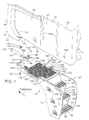
- a retractable stairway assembly in accordance with the present invention is shown in Figs. 1-3.
- the stairway assembly 10 may be attached to a cab 12 of a truck 14, but could also be attached to the frame of the truck.
- the stairway assembly When attached to the cab of a conventional cab over engine truck, the stairway assembly may be lifted with the cab when the engine is being serviced.
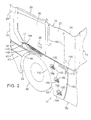
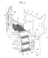
- the stairway assembly 10 is stored underneath the cab 12 in a retracted position, as shown in Fig. 2, but the stairway assembly 10 is movable into extended positions, in which the stairway assembly 10 is exposed, as shown in Fig. 3, to allow a truck passenger to enter or exit the cab 12 by ascending or descending the stairway assembly.
- the stairway assembly 10 includes an actuator 16 that is operable to automatically shift the stairway assembly 10 from the retracted position to the extended position when a door 20 to the cab 12 is opened.
- the actuator 16 is also operable to automatically shift the stairway assembly from the extended to retracted position when the door is closed. This automatic operation, in the illustrated embodiment occurs unless other predetermined conditions exist, as will be explained in greater detail later.
- the stairway assembly 10 could be manually operated, for example by a user simply moving the assembly manually to an open or closed position.
- a mechanical linkage (not shown) may be connected between the stairway assembly 10 and the door 20 to transmit the motion of opening or closing the door 20 to the stairway assembly 10.
- the cab 12 of the truck 14 has a forward body portion 18 spaced longitudinally along the truck from a side body panel portion 24.
- the door 20 spans the space between the forward body portion 18 and the side body panel portion 24 and is pivotable between a closed position, as shown in Fig. 2, and an open position, as shown in Fig. 3.
- a stairwell which pivots between open and closed positions is preferred, other mounting approaches, for example, sliding or other mechanisms may be used to couple the stairway assembly to the cab.
- the door 20 has an exterior side surface 26 with a door handle 28 recessed in its lower, right-hand corner, as shown in Fig. 2.
- the exterior side 26 of the door 20 is substantially aligned with the exterior side surface 27 of the side panel 24 and the exterior side surface 29 of the forward body portion 18 adjacent the door 20, when the door is in the closed position.
- the term "substantially aligned” is meant to encompass situations in which a surface is configured to aesthetically match the contours of the vehicle. Thus, perfect or flush alignment is not required, nor are planar surfaces although a situation where a self contained stairwell is simply mounted to a vehicle surface, as opposed to being built in so as to recess at least partially into the surface, is excluded from this definition.
- the forward body portion 18 of the truck 14 has a lower extension 30 that protrudes downwardly past the bottom edge 32 of the door 20 and the bottom edge 34 of the side panel 24.
- the truck 14 also includes a bumper 40 beneath the bottom edge 36 of the extension 30 and the forward portion 41 of the door 20.
- the exterior face 44 of the bumper 40 is substantially aligned with the exterior side surface 29 of the forward body portion 18 of the truck 14.
- the rearward edge 42 of the bumper 40 is concavely, arcuately-shaped and generally mimics the shape of a forward wheel 45 adjacent thereto.
- the rearward edge 42 of the bumper 40, together with the stairway assembly 10, define a forward wheel well 46, as will be discussed in greater detail below.
- the stairway assembly 10 includes a stairway 48 (Fig. 1) protruding in a perpendicular direction from the back face 50 of an upright panel 52.
- the illustrated stairway includes a stairway frame 53 supporting an elongated, top platform 54 and in this case three steps: a top step 56, a middle step 58, and a bottom step 60, as shown in Figs. 1 and 3.
- the parts of the stairway assembly 10 are described in locational terms, such as “forward,” “rearward,” “inboard,” etc., as the parts are positioned in Fig. 1 relative to the truck 14.
- the illustrated stairway frame 53 has two frame rails 62, 63, in this case square extrusions, one on each side of the stairway.
- the frame rails 62, 63 are arcuate and are upwardly extending to help define a portion of the wheel well 46 and preferably form a rear quarter fender.
- the frame 53 also includes an inboard gusset assembly 64 mounted, such as by bolting, to the inboard frame element 62 and an outboard gusset assembly 65 mounted similarly to the outboard frame element 63.
- Both the inboard and outboard gusset assemblies 64, 65 may be made of a thin, durable material such as commonly used in truck exterior components, with aluminum, fiberglass, plastic, or steel being exemplary materials.
- Each of the gusset assemblies 64, 65 is similarly shaped and constructed. Therefore, only the inboard gusset assembly 64 is described.
- the inboard gusset assembly 64 has a combined bottom gusset 66 and middle gusset 70, and a separate top gusset 72.
- the bottom gusset 66 is essentially triangular, with one side 73 extending from just above the bottom step 60 along the edge of the inboard frame element 62 to the middle step 58.
- the outward side 74 of the bottom gusset 66 extends from just above the bottom step 60 diagonally outward from the inboard frame element 62 to the outward edge 75 of the middle step 58, and the top side 76 of the bottom gusset 66 extends along the middle step 58.
- the middle gusset 70 is shaped similarly to the bottom gusset 68 but extends from just above the middle step 58 to the outward edge 78 of the top step 56.
- the bottom and middle gussets 68, 70 provide support and mounting locations for the middle and top steps 58, 56, respectively.
- the bottom step 60 is supported by a rectangular bottom step frame 82 mounted to the bottom of frame elements 62, 63.
- the top gusset 72 is also somewhat triangular, with one of its edges following the curvature of the inboard extrusion 62 between the top platform 54 and a location near the top step 56.
- the top gusset 72 provides support to the stairway assembly, which is cantilevered from the top platform 54.
- the steps 56, 58, 60 are formed by mounting treads 100, or step surfaces, to the bottom step frame 82 and the top sides 76 of the bottom and middle gussets 66, 70.
- the top sides 76 of the gussets 66, 70 have tabs (not shown) that extend underneath the treads 100 for facilitating the mounting of the treads thereon.
- the outward edges 75, 78, 84 of the treads 100 are curved downwardly, and the inward edges 86, 88, 90 of the treads are curved upwardly to increase the rigidity of the treads.
- the steps 56, 58, 60 ascend along the panel 52 beginning with the bottom step 60 adjacent the rearward, bottom comer of the panel, and ending with the top platform 54 adjacent the opposite comer of the panel so that the top platform is appropriately positioned relative to the door opening 61 when the stairway assembly 10 is in the extended position.
- a wheel well defining member such as a sheet 92 of glass reinforced polyester or other suitable material, extends the width of the steps 56, 58, 60 and is mounted to the frame elements 62, 63 behind the steps.
- the sheet 92 does not provide rigidity to the stairway frame.
- the sheet 92 defines the wall of the rear fender well and prevents mud or the like from splashing up on the steps.
- the sheet 92 is preferably covered on its back with an indoor/outdoor carpet (not shown), such as artificial grass, to further inhibit splashing of water from the wheel well.
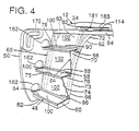
- the top platform 54 is substantially rectangular and is supported by the frame, and more particularly by four box beams along the perimeter edges of the platform with a plurality of stringers or cross pieces (e.g. three equally spaced box beam braces) therebetween. Thus, each box beam extends along a side of the perimeter of the top platform.
- a top plate 106 and a bottom plate 108 (Fig. 4) are fastened to the tops and bottoms, respectively, of the box beams 104.
- the top plate 106 has a tread 110 formed in a substantial portion thereof.
- a forward area 112 of the top plate 106 and a narrow strip area 114 along the inboard side of the top plate 106 are left smooth to facilitate mounting hardware thereon, which will be discussed in greater detail later, and to provide an enclosed area at those locations so that, if necessary, electronics and operating mechanisms can be stored between the top and bottom plates in these areas.
- the outboard step 118 is approximately centered about a center transverse line of the top platform 54 and has a slightly, curved outboard edge 120 that tapers from the rear side 122 of the step 118 to the forward side 124 so as to minimize drag caused by the step 118.
- the step 118 protrudes past the exterior surfaces 27, 29 of the truck 14, as shown in Fig. 2, to provide a stepping surface when the stairway 48 is in the retracted position.
- the panel 52 is fastened to the outboard side of the stairway 48.
- the illustrated panel 52 is essentially planar and, when in the retracted position, spans the area between the wheel well 46 and a lower side body portion 130 of the truck 14, as shown in Fig. 2.
- the panel 52 is shaped to bound and define a portion of the wheel well 46. More specifically, the panel 52 has a forward edge 140 with an arcuate cut-out 142 (Fig. 2) that, in the illustrated embodiment, begins a small distance below the top edge 144 of the panel 52 and extends over half the length of the panel, thus defining an elongated, narrow band 146 at the top, forward side of the panel.
- the panel 52 also has a slightly curved rearward edge 150 that, when the stairway assembly 10 is moved into the retracted position, overlaps and is stopped by a ledge 152 extending behind and parallel to the forward edge 154 of the lower side body portion 130 of the truck 14, as shown in Fig. 3.
- the panel 52 is preferably made from a durable material such as fiberglass, plastic, aluminum, or steel.
- a suitable material is glass reinforced unsaturated polyester composite.
- the panel 52 hides the steps 56, 58, 60 from view.
- the steps are beneath the cab 12.
- the panel 52 is nearly flush, or substantially aligned, with adjacent surfaces on the truck 14, including the exterior surfaces of the door 20, of the side panel 24, and of the extension 30.
- the stairway 48 does not detract from the sleek appearance of the truck 14 or, in the illustrated form, protrude into the air flow path over the side of the truck.
- the steps 56, 58, 60 and platform 54 extend perpendicularly inward from the side of the truck 14, with the bottom step 60 being the most rearward and the top platform 54 being the most forward relative to the front and back of the truck 14.
- the stairway 48 In the extended position, as shown in Fig. 3, the stairway 48 is positioned so that a passenger can conveniently walk up the stairway 48 to the level of the cab 12.
- the stairway assembly 10 of the present invention eliminates the need for passengers to use their hands to climb into the cab 12. Nevertheless, handrails 160 are provided on the side body fairing 24 for safety reasons.
- the bottom step 60 is positioned furthest away from the truck and the steps 56, 58, 60 ascend to the top platform 54, which is just beneath the door opening 61, providing safe and easy access to and from the cab.
- the panel 52 also is provided with three foot receiving openings 162 that allow access to and from the cab 12 for passengers desiring to enter or exit the cab 12 while the stairway 48 is in the retracted position. For instance, when the stairway is maintained in a retracted position because there is insufficient clearance between the side of the truck 14 and an adjacent object.
- Each illustrated opening 162 is "D"-shaped with the linear portion of the "D” forming a bottom edge 166 beneath the opening. As shown in Fig. 2, each bottom edge 166 is aligned with the top of a tread 100, and the openings 162 are sized to accommodate a booted foot.
- a user can step into the openings 162 with their foot reaching the tread 100 to climb into or out of the cab 12 when the stairway 48 is in the retracted position. Because the openings 162 are adjacent the steps 56, 58, 60, when the panel 52 is viewed in the retracted position, the openings follow the same arcuate path as the wheel well 46, providing an aesthetically pleasing appearance.
- the panel 52 optionally is provided with a handle or a handhole 170 (Fig. 3), shown in the upper right corner of the panel, for assisting a passenger who enters or exits the cab 12 using the openings 162 or for assisting to manually open or close the stairway assembly 10.
- a handle or a handhole 170 shown in the upper right corner of the panel, for assisting a passenger who enters or exits the cab 12 using the openings 162 or for assisting to manually open or close the stairway assembly 10.
- the stairway assembly 10 optionally includes an inboard splash guard 167 mounted to the inboard square extension 62.
- the splash guard 167 is the same shape as the panel 52 but has a slightly smaller outline to allow the splash guard 167 to swing past the ledge 152 against which the panel 52 rests.
- the stairway assembly 10 is coupled to the truck 14.
- the stairway assembly 10 is pivotally mounted to a frame member (not shown) of the truck 14.
- a pivot receiving hole 172 is provided at the outboard, forward corner of the top platform 54.
- a pivot 176 having a pivot pin 178 is bolted or otherwise fastened to the frame member so that the pivot pin 178 extends through the hole 172.
- the pivot pin is held in place with fastener 180. This mounting allows the stairway assembly 10 to pivot between the retracted and extended positions about an upright, preferably vertical, axis, coinciding with the longitudinal axis of the pivot pin 178.
- the stairway assembly 10 is also connected to the truck 14 by a first and second slides 180, 181 and accompanying first and second guide tracks 182, 183, as indicated in Fig. 1.
- the first slide 180 is mounted at the forward, inboard corner of the top platform 54.
- the second slide 181 is mounted near the middle of the narrow strip area 114 of the top platform 54.
- the first and second slides 180, 181 each include a respective support bracket 184, 185, which is bolted to the top platform 54, and a respective slide block 186, 187 mounted to the support bracket 184, 185, preferably by bolting.
- the first and second guide tracks 182, 183 are mounted to frame members (not shown) of the truck 14 in position to slidably receive the blocks 186, 187.
- the guide tracks 182, 183 are each arcuate and have a "C"-shaped cross-section. The radii of the bends of the guide tracks 182, 183 are readily determined by geometry.
- the guide tracks are typically of a durable material such as steel.
- the blocks 186, 187 of the slides 180, 181 slidably fit within the openings of the guide tracks 182, 183 and slide therein.
- the guide tracks 182, 183 and slides 180, 181 provide support to the stairway assembly 10 while allowing the stairway assembly to pivot between the retracted and extended positions.
- the slides 180, 181 preferably are made from a friction reducing material, such as ultra-high molecular weight polyethylene, although other materials or slide structures may be used instead.
- the illustrated cylinder actuator 16 is mounted at its rearward end 188 to a bracket at the inboard comer of the forward edge 189 of the stairway assembly 10 at a location spaced from the pivot 178, or could be mounted directly thereto.
- the forward end 190 of the actuator 16 is mounted to a frame member (not shown) of the truck 14, as indicated in Fig. 1.
- the actuator 16 is preferably a fluid cylinder such as a hydraulic cylinder or an air cylinder, but may alternatively be an electric motor or other suitable movement generating device.
- the actuator 16 when the stairway assembly 10 is retracted, the actuator 16 is also retracted. As the actuator 16 is extended, it exerts a force against the forward, inboard comer of the top platform 54, causing the stairway assembly 10 to pivot about the axis of pivot pin 178 in a clockwise direction from the retracted to the extended position.
- the illustrated embodiment shows the extended position at about a 45° angle from the side of the truck 14; however, other angles could be achieved, for example by using a cylinder having a different length stroke, a different type actuator, or using control signals sent by sensors to stop the stairway 48 upon the happening of some contingency, such as will be discussed later.
- the actuator 16 is retracted, exerting a pulling force on the forward, inboard corner of the platform 54, which causes the stairway assembly 10 to pivot counterclockwise in Fig. 1 from the extended to the retracted position.
- the retraction force may be applied by a spring.
- the retracted position of the illustrated embodiment is defined by the ledge 152 on the lower side body portion 130.
- control assembly may include a microprocessor for processing input signals from sensors and switches to control the actuator, as described more fully below.
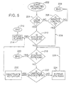
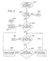
- the control assembly may include sensors and switches that are hard-wired to operate the stairway system. Either way, the control assembly may operate in accordance with the logic shown in the flowcharts in Figs. 5 and 6.
- the decision blocks represent determinations by a microprocessor or the logic of the hard-wired circuit.
- the sensors include a door position sensor 191 (Fig. 1) for sensing if the door 20 is open, a stairway position sensor 192 (Fig. 3) for sensing if the stairway is retracted, and an extension and retraction limiter sensor 194 (or sensors) (Fig. 1) for sensing obstacles to the movement of the stairway.
- the sensors 191, 192, 194 may be of any type known in the industry for achieving the stated purposes.
- the stairway position sensor 191 and the door position sensors 192 may be microswitches and the limiters 194 may be strain gauges for detecting strain on the stairway in the event the stairway encounters obstacles during opening or closing, optical sensors for checking if the pathway for the stairway 48 is clear, or other suitable sensors.
- the stairway assembly 10 optionally includes an occupant sensor for sensing the presence of a person or other object on the stairway.
- the occupant sensor may be, for example, a mechanical interlock having teeth for engaging a slot when the sag on the stairway assembly 10 attained a certain predetermined amount. The engagement of the teeth in the slot would prevent movement of the stairway assembly 10.
- the circuit may also include a remote control switch 195, such as a key-operated switch, for activating the stairway 48 to extend or retract or to deactivate the stairway assembly 10 regardless of the door position.
- a remote control switch 195 such as a key-operated switch, for activating the stairway 48 to extend or retract or to deactivate the stairway assembly 10 regardless of the door position.
- the remote control switch 195 may be mounted remote from the door 20 at a lower portion of the side panel 24 of the cab 12.
- another deactivation switch 196 such as a interdiction switch as shown in Fig. 3, is mounted preferably to the interior of the door 20 so that a person inside the truck 14 can deactivate the system to prevent the stairway 48 from opening.
- the remote control deactivation switches 195, 196 are particularly useful in situations where there is not enough clearance between the truck 14 and an adjacent object, such as another parked vehicle or a tree, to extend the stairway 48. Also, the remote control switch 195 allows a user to cause the stairway to open with the user in position to climb the stairway 48 without the door 20 being opened.
- the control assembly operates to extend the stairway 48 as follows.
- the microcontroller monitors the door position sensor to see whether the door 20 is open, as represented by decision block 204. If the door 20 is not open, the microcontroller monitors the remote control switch 195, as represented by decision block 206. If the remote control switch 195 is not activated, no action occurs, as represented by block 208. If the remote control switch 195 is activated, then the microprocessor continues to block 218, as indicated by line 209.
- the microprocessor checks the actuator 16 to see if it is disabled, as represented by decision block 212.
- the actuator 16 could be disabled, for example, by the deactivation switch 196 or the remote control switch 195. If the actuator 16 is disabled when the door is open, then an alarm is sounded, as represented by block 214 to alert passengers that the door 20 is open but the stairway 48 is not extended so that they are not injured by exiting the cab 12 assuming the stairway 48 to be in the extended position. No further action occurs, as indicated by block 216.
- the microprocessor checks the stairway position sensor to see if the stairway 48 is extended, as represented by decision block 218. If the stairway 48 is extended, then no action occurs, as represented by block 220.
- the microprocessor checks to see if the limiter sensor 194 has sensed an encounter with an obstacle. This is done to determine if the stairway 48 has impacted an object, as represented by decision block 222. If no object is encountered, then the actuator 16 is activated to move the stairway 48 into the extended position, as indicated by block 224. The process of monitoring the extension of the stairway 48 continues again at decision block 218, as indicated by line 228. When the stairway is fully extended, block 220 is reached and the operation stops.
- the actuator is deactivated, as indicated at block 230, and the alarm is sounded, as indicated at block 214. No further action occurs, as indicated at block 216.
- the control assembly operates to retract the stairway 48 as follows.
- the microcontroller monitors the door position sensor to check whether the door 20 is closed or the switch 195 is in the retract position, as represented by decision block 252. If the door 20 is not closed or switch 195 is not in the retract position, no further action occurs, as indicated by block 253. If the door 20 is closed, or the switch 195 is in the retract position, the microprocessor checks to see if the actuator 16 is disabled, as represented by decision block 254. If the actuator is not disabled, the microcontroller checks the stairway position sensor to see if the stairway 48 is retracted, as represented by decision block 256. If the stairway 48 is retracted, the retraction process is complete and no further action occurs, as indicated by terminator block 258.
- the microprocessor checks the limiter sensor 194 to see if an obstacle is encountered, as represented by decision block 260.
- the actuator 16 is deactivated as indicated in block 262 and the alarm is sounded as indicated in block 264. No further action occurs as indicated in block 266.
- the actuator 16 is activated to retract the stairway 48 as indicated in block 270. Then, the process continues again at decision block 256, as indicated by line 272, until the stairway is fully retracted as determined at block 256.
- the stairway assembly of the present invention permits comfortable and safe entry to and exiting from the cab.
Landscapes
- Engineering & Computer Science (AREA)
- Mechanical Engineering (AREA)
- Vehicle Step Arrangements And Article Storage (AREA)
- Lock And Its Accessories (AREA)
- Body Structure For Vehicles (AREA)
- Handcart (AREA)
Claims (32)
- Einziehbare Treppenanordnung (10) für ein Fahrzeug (14) mit einem Führerhaus (12), einer Tür (20) zu dem Führerhaus (12), die eine untere Kante (32) aufweist, und einem an das Führerhaus (12) angrenzenden Seitenabschnitt (24), wobei die Treppenanordnung umfaßt:gekennzeichnet durch eine oberste Stufenplattform (54), die durch die Treppe (48) unterstützt ist und einen vorstehenden Abschnitt (118) aufweist, der über die untere Kante (32) der Tür (20) hinaus nach außen ragt, wenn die Treppe (48) in der eingezogenen Position ist und die Tür (20) geschlossen ist, wobei die oberste Stufenplattform (54) mit der Treppe (48) bewegbar ist, wenn die Treppe (48) zwischen der ausgezogenen und der eingezogenen Position bewegt wird.eine Platte (52) mit einer Vorderseite und einer Rückseite (50),eine Treppe (48) mit einer Anzahl von Stufen (56, 58, 60), wobei Stufenoberflächen (100) mit der Platte (52) verbunden sind und in einer Richtung weg von der Rückseite (50) der Platte (52) vorstehen; wobei die Treppe (48) und die Platte (52) bewegbar sind zwischen einer eingezogenen Position, in der die Platte (52) im wesentlichen mit dem Seitenabschnitt (24) ausgerichtet ist und sich die Treppe (48) hinter der Platte (52) mit den Stufenoberflächen (100) nach oben zeigend befindet, und mindestens einer ausgezogenen Position, in der die Treppe (48) ausgefahren ist, um einen Zugang zu und einen Ausstieg aus dem Führerhaus (12) zu ermöglichen,
- Treppenanordnung nach Anspruch 1, dadurch gekennzeichnet, daß die Tür (20) mindestens eine offene Position und eine geschlossene Position aufweist und daß die Platte (52) und die Treppe (48) schwenkbar an dem Fahrzeug (14) angebracht sind, zum Schwenken um eine senkrechte Treppen-Schwenkachse, wenn die Treppe (48) und die Platte (52) sich zwischen den eingezogenen und den ausgezogenen Positionen bewegen, und daß die Treppenanordnung (10) weiterhin einen Stellantrieb (16) umfaßt, der mit der Treppe (48) an einer Stelle verbunden ist, die beabstandet ist von der Treppen (48)-Schwenkachse, und der zum Bewegen der Treppe (48) zwischen der eingezogenen und ausgezogenen Position auf eine nach Betätigung des Stellantriebs (16) hin betätigbar ist.
- Treppenanordnung nach Anspruch 2, gekennzeichnet durch einen Türpositionssensor (191) und eine Treppenpositions-Steuereinheit, die als Antwort auf den Türpositions-Sensor (191) betätigbar ist, um den Stellantrieb (16) zu veranlassen, die Treppe (48) von der eingezogenen Position zu einer ausgezogenen Position bei Öffnen der Tür (20) und von einer ausgezogenen Position zu einer eingezogenen Position bei Schließen der Tür (20) zu verlagern, und durch einen Treppenbewegungs-Deaktivator (196), der betätigbar ist, um die Bewegung der Treppe (48) zwischen der eingezogenen und der ausgezogenen Position selektiv zu blockieren, wobei der Deaktivator einen manuell betätigbaren Schalter (196) umfaßt.
- Treppenanordnung nach einem der Ansprüche 2 oder 3, dadurch gekennzeichnet, daß der Stellantrieb (16) ein Motor ist.
- Treppenanordnung nach einem der Ansprüche 2 oder 3, dadurch gekennzeichnet, daß der Stellantrieb (16) ein Fluidzylinder ist.
- Treppenanordnung nach Anspruch 1, dadurch gekennzeichnet, daß die Treppe (48) eine Anzahl von Stufen (56, 58, 60) aufweist und die Platte (52) zwei aufrechte Seitenkanten (74, 78), eine obere Kante (144) und eine untere Kante hat, wobei die Stufen (56, 58, 60) entlang der Platte (52) beginnend mit einer ersten Stufe (60), die benachbart zu einer Seitenkante (74) und zu einer unteren Kante angeordnet ist, und endend mit der obersten Stufe (56), die benachbart zu der anderen Seitenkante (78) und der oberen Kante (144) angeordnet ist, aufsteigen, wobei während einer Bewegung der Treppe (48) die erste Stufe (60) und die oberste Stufe (56) relativ zueinander an einer festen Stelle verbleiben.
- Treppenanordnung nach Anspruch 1, dadurch gekennzeichnet, daß die Tür (20) eine geschlossene Position und eine offene Position aufweist und daß die Treppenvorrichtung weiterhin umfaßt:wobei mindestens ein Gleitelement (180, 181) innerhalb mindestens einer Führungsbahn (182, 183) verfahrbar ist, wenn die Tür (20) sich zwischen der geschlossenen und der offenen Position bewegt.mindestens ein Gleitelement (180, 181), das zum Koppeln mit entweder der Tür (20) oder der Treppe (48) angepasst ist, undmindestens eine im wesentlichen horizontale Führungsbahn (182, 183), die zum Koppeln mit dem jeweils anderen Element, der Tür (20) oder der Treppe (48), angepaßt ist,
- Treppenanordnung nach Anspruch 1, dadurch gekennzeichnet, daß eine Kotflügelanordnung an den Seitenabschnitt (24) des Führerhaus-Grundkörpers angrenzt und die Kotflügelanordnung einen vorderen Viertel-Kotflügel und einen hinteren Viertel-Kotflügel aufweist, wobei jeder der vorderen und hinteren Viertel-Kotflügel eine bogenförmige Kante (42, 142) hat, die zusammen den Radschacht (46) definieren, wobei der hintere Viertel-Kotflügel schwenkbar um eine senkrechte Achse zwischen einer eingezogenen Position und einer ausgezogenen Position ist, in der die Stufen (56, 58, 60) jenseits des Seitenabschnitts (24) des Führerhaus-Grundkörpers (12) freiliegen und so angeordnet sind, daß sie einen Zugang zu und von dem Führerhaus (12) ermöglichen.
- Treppenanordnung nach Anspruch 8, dadurch gekennzeichnet, daß die Stufen jeweils eine Stufenoberfläche aufweisen und daß der hintere Viertel-Kotflügel weiterhin eine Anzahl von durch die Platte festgelegten Stufenöffnungen umfaßt, wobei jede dieser Öffnungen an eine jeweilige Stufenoberfläche angrenzt.
- Treppenanordnnug nach Anspruch 9, dadurch gekennzeichnet, daß der Treppenpositions-Sensor (192) an dem Fahrzeug (14) angebracht ist und zum Delektieren und Anzeigen einer Position der Treppe (48) angepasst ist.
- Treppenanordnung nach Anspruch 10, dadurch gekennzeichnet, daß die Tür (20) zwischen geschlossenen und offenen Positionen bewegbar ist, und die Treppenvorrichtung weiterhin umfaßteinen Türpositions-Sensor (191), der die Position der Tür (20) ermittelt,eine Alarmeinheit, die funktional mit dem Treppenpositions-Sensor (192) und dem Türpositions-Sensor (191) verbunden ist, wobei die Alarmeinheit aktiviert wird, wenn der Türpositions-Sensor (191) anzeigt, daß die Tür (20) offen ist, und der Treppenpositions-Sensor (192) anzeigt, daß die Treppe (48) eingezogen ist.
- Treppenanordnung nach Anspruch 11, gekennzeichnet durch einen Besetzungs-Sensor (194), der funktional mit der Treppe (48) verbunden und so angepaßt ist, daß er, zumindest wenn ein Bewegen der Treppe (48) versucht wird, detektiert, ob sich eine Person auf der Treppe befindet.
- Treppenanordnung nach Anspruch 12, dadurch gekennzeichnet, daß der Besetzungs-Sensor (194) detektiert, ob eine Kraft, die auf die Treppe (48) in einer Abwärtsrichtung aufgebracht wird, einen vorbestimmten Wert überschreitet.
- Treppenanordnung nach Anspruch 11, gekennzeichnet durch einen Hindernis-Sensor, der funktional mit der Treppe (48) verbunden und so angepasst ist, daß er Hindernisse gegenüber einer Bewegung der Treppe (48) detektiert.
- Treppenanordnung nach Anspruch 14, dadurch gekennzeichnet, daß der Hindernis-Sensor Dehnungsmesseinheiten aufweist.
- Treppenanordnung nach Anspruch 1, dadurch gekennzeichnet, daßder Fahrzeugseitenabschnitt (24) einen vorderen Viertel-Kotflügel (40) und einen hinteren Viertel-Kotflügel aufweist, wobei der vordere und hintere Viertel-Kotflügel einen Radschacht (46) definieren, in dern ein Rad (45) angeordnet ist,die Platte (52) der Anordnung zumindest einen Abschnitt des hinteren Viertel-Kotflügels bildet,die Treppe (48) und die Platte (52) zum Schwenken um eine senkrechte Treppen-Schwenkachse zum Bewegen zwischen der eingezogenen Position und zumindest einer ausgezogenen Position schwenkbar an dem Fahrzeug (14) angebracht sind, unddie oberste Stufenplattform (54) in der Richtung von vorn nach hinten verlängert ist und sich zumindest teilweise über den oberen Abschnitt des Rades (45) erstreckt, zumindest wenn die Treppe (48) in der eingezogenen Position ist, wobei ein Treppen-Schwenkpunkt (176) vor der Mitte des Rades (45) angeordnet ist.
- Treppenanordnung nach Anspruch 16, dadurch gekennzeichnet, daß die Treppenanordnung weiterhin einen ersten Türpositions-Sensor (191), einen zweiten Treppenpositions-Sensor (192) und eine Alareinheit umfaßt, die ansprechend auf die ersten und zweiten Sensoren (191, 192) aktiviert wird, wenn die Tür (20) offen ist und die Treppe (48) in der eingezogenen Position ist.
- Treppenanordnung nach Anspruch 17, gekennzeichnet durch erste und zweite bogenförmige Führngsbahnen (182, 183) und erste und zweite bogenförmige Gleitelemente (180, 181), wobei das erste Gleitelement (180) verschiebbar innerhalb der ersten Führungsbahn (182) und das zweite Gleitelement (183) verschiebbar innerhalb der zweiten Führungsbahn (183) ist und wobei die Platte (52) und die Treppe (48) schwenkbar mit dem Fahrzeug (14) verbunden sind, um zwischen den ausgezogenen und eingezogenen Positionen zu verschwenken, wobei die Gleitelemente (180, 181) in den Führungsbahnen (182, 183) gleiten, wenn die Platte (52) und die Treppe (48) sich zwischen eingezogenen und ausgezogenen Positionen bewegen.
- Treppenanordnung nach Anspruch 1, dadurch gekennzeichnet, daß die Platte (52) mindestens eine Fußaufnahmeöffnung (162), die an eine der Stufenoberflächen (56, 58, 60) angrenzt, aufweist, durch die zumindest ein Teil der angrenzenden Stufenoberfläche (100) freigelegt ist, wobei ein Fuß in der mindestens einen Fußaufnahmeöffnung (162) positioniert werden kann, um in das Führerhaus (12) zu steigen, wenn die Treppe (48) und die Platte (52) in der eingezogenen Position sind.
- Treppenanordnung nach Anspruch 19, gekennzeichnet durch eine Anzahl von Fußaufnahmeöffnungen (162), die jeweils angrenzend an eine jeweilige Stufe (56, 58, 60) angeordnet sind, wobei jede Fußaufnahmeöffnung (162) entlang eines unteren Abschnitts (166) durch einen Platten-Stufenabschnitt (100) begrenzt ist, der im wesentlichen horizontal ist und mit der angrenzenden Stufe (56, 58, 60) fluchtet.
- Treppenanordnung nach Anspruch 16, dadurch gekennzeichnet, daß zumindest eine untere der Anzahl von Stufen (56, 58, 60) und die senkrechte Achse auf gegenüberliegenden Seiten der Mitte des Rades (45) angeordnet sind, zumindest wenn die Treppe (48) in der eingezogenen Position ist.
- Treppenanordnung nach Anspruch 16, dadurch gekennzeichnet, daß ein Stellantrieb (16) der vor der Mitte des Rades (45) angeordnet ist und mit der Treppe (48) zum automatischen Bewegen der Treppe (48) zwischen den ausgezogenen und eingezogenen Positionen, wenn die Tür (20) geöffnet oder geschlossen wird, verbunden ist.
- Treppenanordnung nach Anspruch 16, dadurch gekennzeichnet, daß die Platte (52) im wesentlichen mit dem vorderen Viertel-Kotflügel (40) ausgerichtet ist, wenn die Treppe (48) in der eingezogenen Position ist, und daß zumindest ein Abschnitt der Platte (52) hinter der Mitte des Rades (45) angeordnet ist.
- Treppenanordnung nach Anspruch 16, dadurch gekennzeichnet, daß jede der Anzahl von Stufen (56, 58, 60) eine Stufenoberfläche (100) hat, und daß die senkrechte Platte (52) mehrere Fußaufnahmeöffnungen (162) aufweist, die jeweils einer entsprechenden Stufenoberfläche (100) zugeordnet sind und durch die zumindest ein Teil der entsprechenden Stufenoberfläche freigelegt ist, wobei ein Fuß durch die Fußaufnahmeöffnungen (162) positioniert sein kann, um in das Führerhaus (12) zu steigen, wenn die Treppe (48) und die Platte (52) in der eingezogenen Position sind.
- Treppenanordnung nach Anspruch 16, dadurch gekennzeichnet, daß die Treppe (48) um eine vertikale Achse in zumindest eine ausgezogene Position schwenkbar ist, in der die Treppe (48) so positioniert ist, daß sie Zugang zu und Ausstieg aus dem Führerhaus (12) ermöglicht.
- Treppenanordnung nach Anspruch 16, dadurch gekennzeichnet, daß die Tür (20) in einer Richtung um eine senkrechte Tür-Schwenkachse zwischen der geschlossenen und geöffneten Position schwenkbar ist, und daß die Treppe (48) in die gleiche Richtung schwenkbar ist wie die Tür (20).
- Treppenanordnung nach Anspruch 26, dadurch gekennzeichnet, daß die senkrechte Tür-Schwenkachse von der senkrechten Schwenkachse der Treppe (48) beabstandet ist.
- Treppenanordnung nach Anspruch 16, dadurch gekennzeichnet, daß die Stufen (56, 58, 60) im wesentlichen senkrecht nach außen von der Rückseite (50) der Platte (52) ragen, so daß, wenn die Treppe (48) in der eingezogenen Position ist, die Stufen (56, 58, 60) unterhalb des Fuhrerhauses (12) sind.
- Treppenanordnung nach Anspruch 28, dadurch gekennzeichnet, daß in der Platte (52) eine Haltegriff (170) gebildet ist.
- Treppenanordnung nach Anspruch 28, dadurch gekennzeichnet, daß die vergrößerte oberste Stufenplattform (54) nach außen von der Vorderseite der Platte (52) herausragt, so daß die oberste Stufenplattform (54) zum Betreten während des Zugangs zu oder des Ausstiegs aus dem Führerhaus (12) angeordnet ist, wenn die Stufen (56, 58, 60) unterhalb des Führerhauses (12) sind.
- Treppenanordnung nach Anspruch 22, dadurch gekennzeichnet, daß das Führerhaus (12) einen Rahmen (53) aufweist und der Stellantrieb (16) mit der Treppe (48) verbunden und angepaßt ist zur Anbringung an dem Führerhaus (12) oder dem Rahmen (53), und betätigbar ist zum Schwenken der Treppe (48) zwischen der eingezogenen und ausgezogenen Position ansprechend auf eine Bewegung der Tür (20) in und aus der geschlossenen Position.
- Fahrzeug (14), gekennzeichnet durch eine Treppenanordnung (10) nach einem der vorhergehenden Ansprüche.
Applications Claiming Priority (3)
| Application Number | Priority Date | Filing Date | Title |
|---|---|---|---|
| US08/818,806 US6179312B1 (en) | 1997-03-14 | 1997-03-14 | Retractable stairway for entering and exiting a vehicle |
| US818806 | 1997-03-14 | ||
| PCT/US1998/004961 WO1998040241A1 (en) | 1997-03-14 | 1998-03-13 | Retractable stairway for entering and exiting a vehicle |
Publications (2)
| Publication Number | Publication Date |
|---|---|
| EP0966367A1 EP0966367A1 (de) | 1999-12-29 |
| EP0966367B1 true EP0966367B1 (de) | 2003-05-14 |
Family
ID=25226465
Family Applications (1)
| Application Number | Title | Priority Date | Filing Date |
|---|---|---|---|
| EP98910372A Expired - Lifetime EP0966367B1 (de) | 1997-03-14 | 1998-03-13 | Einziehbare treppe für ein und aussteigen aus einem kraftfahrzeug |
Country Status (7)
| Country | Link |
|---|---|
| US (1) | US6179312B1 (de) |
| EP (1) | EP0966367B1 (de) |
| JP (1) | JP2001516303A (de) |
| AT (1) | ATE240225T1 (de) |
| AU (1) | AU6462698A (de) |
| DE (1) | DE69814599T2 (de) |
| WO (1) | WO1998040241A1 (de) |
Cited By (3)
| Publication number | Priority date | Publication date | Assignee | Title |
|---|---|---|---|---|
| CN110509854A (zh) * | 2019-08-16 | 2019-11-29 | 一汽解放汽车有限公司 | 一种踏板装置和汽车 |
| US11987953B2 (en) | 2019-11-25 | 2024-05-21 | Manitou Italia S.R.L. | Access ladder for a vehicle |
| IT202300018495A1 (it) * | 2023-09-08 | 2025-03-08 | Dieci S R L | Telehandler rotativo |
Families Citing this family (91)
| Publication number | Priority date | Publication date | Assignee | Title |
|---|---|---|---|---|
| US6264227B1 (en) * | 1998-10-01 | 2001-07-24 | Case Corporation | Moveable steps for a vehicle |
| US6178364B1 (en) | 1999-02-12 | 2001-01-23 | Freightliner Corporation | Method of controlling a retractable stairway assembly |
| WO2000047448A1 (en) * | 1999-02-26 | 2000-08-17 | Freightliner Corporation | Method of controlling a retractable stairway assembly |
| AU2981199A (en) * | 1999-02-12 | 2000-08-29 | Freightliner Corporation | Retractable stairway assembly for a vehicle |
| US6264222B1 (en) | 1999-02-25 | 2001-07-24 | Freightliner Llc | Retractable stairway assembly for a vehicle |
| JP2002537175A (ja) * | 1999-02-23 | 2002-11-05 | デコマ エクステリア トリム インコーポレイテッド | モジュール式動力踏み板 |
| AU2481401A (en) | 1999-07-08 | 2001-02-05 | Aai Corporation | Passenger rail car sliding door with high platform threshold |
| SE9903517L (sv) * | 1999-09-29 | 2000-10-23 | Scania Cv Ab | Frambyggd lastbil med icke-tippbar förarhytt |
| SE517908C2 (sv) * | 2000-04-11 | 2002-07-30 | Volvo Articulated Haulers Ab | Drivmotorhus |
| US7584975B2 (en) * | 2001-02-15 | 2009-09-08 | 89908, Inc. | Retractable vehicle step |
| US6641158B2 (en) | 2001-02-15 | 2003-11-04 | American Moto Products, Inc. | Retractable vehicle step |
| JP2002240633A (ja) * | 2001-02-16 | 2002-08-28 | Tokyu Car Corp | 荷台搭載ユニット用階段 |
| CA2463717C (en) * | 2001-10-16 | 2009-07-07 | American Moto Products, Inc. | Retractable vehicle step |
| US7219910B2 (en) * | 2002-07-24 | 2007-05-22 | E. Bradley Dunford | Engine step |
| US7487986B2 (en) * | 2002-10-16 | 2009-02-10 | 89908, Inc. | Retractable vehicle step |
| FR2851527B1 (fr) * | 2003-02-24 | 2006-02-03 | Groupe Mecalac | Vehicule a moteur equipe d'un marchepied escamotable |
| US6971657B2 (en) * | 2003-03-13 | 2005-12-06 | Kalmar Industries Usa, Llc | Driver access system for motor truck tractor |
| US7163221B2 (en) * | 2003-10-31 | 2007-01-16 | 89908, Inc. | Retractable vehicle step with anti-strike/anti-pinch sensor system |
| US20050217939A1 (en) * | 2003-11-05 | 2005-10-06 | Liftup Aps | Lifting system |
| KR100568115B1 (ko) * | 2004-06-30 | 2006-04-05 | 삼성전자주식회사 | 점진적 머지 방법 및 그것을 이용한 메모리 시스템 |
| US8091294B2 (en) * | 2004-12-22 | 2012-01-10 | Whalen Robert F | Folding pet staircase |
| AU2006201027B2 (en) * | 2005-08-02 | 2011-01-06 | Hy-Drive Technologies Ltd. | Hydrogen generating apparatus |
| FR2890348B1 (fr) * | 2005-09-07 | 2009-03-06 | Constructeurs Ass Mat I V A | Dispositif d'acces a un module de rangement dispose au dessus d'une roue de vehicule, du type vehicule d'intervention comprenant un tel dispositif |
| JP4179561B2 (ja) * | 2005-11-08 | 2008-11-12 | 株式会社モリタ | 車両用ステップ装置 |
| US20070159308A1 (en) * | 2006-01-10 | 2007-07-12 | John Johnston | Warning alarm system for retractable motor vehicle steps |
| US8042820B1 (en) * | 2006-10-16 | 2011-10-25 | Dewees Thomas G | Driver's side large vehicle step |
| US9944231B2 (en) | 2006-10-27 | 2018-04-17 | Lund Motion Products, Inc. | Retractable vehicle step |
| US7740261B2 (en) | 2006-10-27 | 2010-06-22 | 89908, Inc. | Tailgate access step |
| US11926286B2 (en) | 2011-10-31 | 2024-03-12 | Lund Motion Products, Inc. | Retractable vehicle step |
| US9346405B2 (en) | 2006-10-27 | 2016-05-24 | Lund Motion Products, Inc. | Retractable vehicle step |
| CA2666495C (en) | 2006-10-27 | 2016-03-01 | 89908, Inc. Dba Amp Research | Tailgate access step |
| US7637519B2 (en) * | 2006-10-30 | 2009-12-29 | 89908, Inc. | Moveable support platform |
| US9701249B2 (en) | 2006-10-27 | 2017-07-11 | Lund Motion Products, Inc. | Retractable vehicle step |
| US7637563B2 (en) * | 2006-11-17 | 2009-12-29 | Daimler Trucks North America Llc | Selectively removable side fairing for a vehicle |
| DE102006055218A1 (de) * | 2006-11-21 | 2008-05-29 | Bayer Technology Services Gmbh | Kontinuierliches Verfahren zur Synthese von nanoskaligen metallhaltigen Nanopartikel und Nanopartikeldispersion |
| US7497501B2 (en) * | 2006-12-20 | 2009-03-03 | Caterpillar Inc. | Ergonomic operator compartment access system and method |
| US7775537B2 (en) * | 2007-01-03 | 2010-08-17 | International Truck Intellectual Property Company, Llc | Ingress/egress steps for a highway truck |
| US7703784B2 (en) * | 2007-03-21 | 2010-04-27 | Nissan Technical Center North America, Inc. | Vehicle structure |
| DE102007033646A1 (de) * | 2007-07-17 | 2009-01-29 | Hs Genion Gmbh | Fahrerkabine eines Fahrzeugs |
| DE102007049768A1 (de) * | 2007-10-17 | 2009-04-23 | Agco Gmbh | Nutzfahrzeug mit klappbarem Abdeckelement |
| US20100019468A1 (en) * | 2008-06-21 | 2010-01-28 | Price L Jay | Apparatus, system and method for accessing the engine compartment of a vehicle |
| US8033482B2 (en) * | 2008-08-14 | 2011-10-11 | Cnh America Llc | Pivoting handrail for an agricultural sprayer |
| US8262113B1 (en) * | 2009-09-24 | 2012-09-11 | Chafey John R | Powered running boards for locking doors of a vehicle |
| DE202011051494U1 (de) * | 2011-09-30 | 2013-01-10 | Al-Ko Kober Ag | Kotflügel mit Einsatzelement |
| CN102628310B (zh) * | 2012-04-10 | 2014-08-13 | 温州市康而达实业有限公司 | 设有折叠护栏的自动隐藏式滑动楼梯 |
| US8827038B2 (en) * | 2012-12-12 | 2014-09-09 | Cnh Industrial America Llc | Ladder assembly for a work vehicle |
| KR101428301B1 (ko) * | 2012-12-21 | 2014-08-07 | 현대자동차주식회사 | 차량용 사이드 스텝의 작동 제어방법 |
| US8899659B2 (en) * | 2013-03-06 | 2014-12-02 | Paccar Inc | Recess steps for cab access |
| US9156406B2 (en) | 2013-09-27 | 2015-10-13 | Lund, Inc. | Modular rail and step system |
| US9120426B1 (en) * | 2014-02-07 | 2015-09-01 | Ford Global Technologies, Llc | Wheelhouse cladding step |
| CN103909871B (zh) * | 2014-03-26 | 2016-09-07 | 杭州天铭科技股份有限公司 | 车辆和用于车辆的脚踏板设备 |
| US9683408B2 (en) * | 2014-06-16 | 2017-06-20 | Randy Jackson | Pivoting stairs |
| US9677249B2 (en) * | 2015-02-19 | 2017-06-13 | Komatsu Ltd. | Work vehicle with stowable user support member |
| JP2018059263A (ja) * | 2015-02-23 | 2018-04-12 | 株式会社小松製作所 | 作業車両及びその制御方法 |
| US9522634B1 (en) | 2015-06-05 | 2016-12-20 | Lund Motion Products, Inc. | Horizontal retractable vehicle step |
| US9550458B2 (en) | 2015-06-05 | 2017-01-24 | Lund Motion Products, Inc. | Retractable step and side bar assembly for raised vehicle |
| US10618472B2 (en) | 2015-08-04 | 2020-04-14 | T-Max (Hangzhou) Technology Co., Ltd. | Vehicle and vehicle step apparatus with multiple drive motors |
| KR101786201B1 (ko) * | 2015-09-15 | 2017-10-17 | 현대자동차주식회사 | 차량의 도어 개방 각도에 연동하여 회전하는 보조스텝 및 그 제어방법 |
| KR101734675B1 (ko) | 2015-09-21 | 2017-05-11 | 현대자동차주식회사 | 캡 틸팅시 스텝으로 변환되는 스플래시 쉴드 어셈블리 |
| US9816318B2 (en) * | 2015-12-11 | 2017-11-14 | David A. Johnson | Powered ladder for large industrial vehicles |
| ITUB20159622A1 (it) * | 2015-12-28 | 2017-06-28 | Manitou Italia Srl | Macchina operatrice semovente |
| US10981609B2 (en) | 2015-12-30 | 2021-04-20 | Nikola Corporation | Systems, methods, and devices for an automobile door or window |
| WO2017117572A1 (en) * | 2015-12-30 | 2017-07-06 | Bluegentech Llc | Systems, methods, and devices for an automobile door or window |
| US10077084B2 (en) | 2015-12-30 | 2018-09-18 | Nikola Corporation | Systems, methods, and devices for an automobile door or window |
| US11001129B2 (en) | 2015-12-30 | 2021-05-11 | Nikola Corporation | Cargo door for semi-truck |
| US10661844B2 (en) | 2015-12-30 | 2020-05-26 | Nikola Corporation | Systems, methods, and devices for an automobile door or window |
| US10787205B2 (en) * | 2016-01-22 | 2020-09-29 | Bombardier Recreational Products Inc. | Fender for a wheeled vehicle |
| JP6786813B2 (ja) * | 2016-02-17 | 2020-11-18 | 株式会社タダノ | 作業車両 |
| US9586527B1 (en) * | 2016-05-18 | 2017-03-07 | Ford Global Technologies, Llc | Wheel well step assembly of vehicle |
| IT201600093806A1 (it) * | 2016-09-19 | 2018-03-19 | Iveco Spa | Cabina di guida di veicolo industriale provvista di scala laterale estraibile per consentire l'accesso alla cabina stessa |
| JP6227807B1 (ja) * | 2016-12-08 | 2017-11-08 | 株式会社小松製作所 | フロントフェンダ及びホイールローダ |
| US10093361B2 (en) * | 2017-03-06 | 2018-10-09 | Kyle Wilson | Adjustable vehicular fender extension |
| US9909355B1 (en) * | 2017-03-20 | 2018-03-06 | Northwest Ag Systems | Door for vehicle steps |
| US20180334104A1 (en) | 2017-05-18 | 2018-11-22 | Ferdinand Rosario | Rotating Vehicle Step |
| GB2562766A (en) * | 2017-05-24 | 2018-11-28 | Alexander Dennis Ltd | Emergency steps for passenger service vehicles |
| US10696232B2 (en) * | 2017-11-16 | 2020-06-30 | Cnh Industrial America Llc | Split deck rail |
| US10384614B1 (en) | 2018-07-20 | 2019-08-20 | T-Max (Hangzhou) Technology Co., Ltd. | Vehicle, running board assembly and drive assembly for running board |
| US11198394B2 (en) | 2018-07-20 | 2021-12-14 | T-Max (Hangzhou) Technology Co., Ltd. | Vehicle running board apparatus and retractable device thereof |
| CN110012061B (zh) | 2019-02-20 | 2022-02-08 | 杭州天铭科技股份有限公司 | 车用装备的管理装置、车辆及服务器 |
| WO2020172914A1 (zh) | 2019-02-28 | 2020-09-03 | 杭州天铭科技股份有限公司 | 绞盘、导绳器和具有离合功能的传动装置 |
| WO2020177186A1 (zh) | 2019-03-05 | 2020-09-10 | 杭州天铭科技股份有限公司 | 车用踏杠设备和车辆 |
| WO2020181617A1 (zh) | 2019-03-11 | 2020-09-17 | 杭州天铭科技股份有限公司 | 调节装置、调节器和减震器 |
| US11584387B2 (en) | 2019-09-16 | 2023-02-21 | T-Max (Hangzhou) Technology Co., Ltd. | Step apparatus for vehicle and vehicle |
| JP7071320B2 (ja) * | 2019-09-20 | 2022-05-18 | 日立建機株式会社 | 作業機械 |
| JP7257624B2 (ja) * | 2019-10-30 | 2023-04-14 | 三菱自動車工業株式会社 | 車両のステップ装置 |
| WO2021227616A1 (zh) | 2020-05-11 | 2021-11-18 | 杭州天铭科技股份有限公司 | 一种车用踏板设备和车辆 |
| WO2021227617A1 (zh) | 2020-05-11 | 2021-11-18 | 杭州天铭科技股份有限公司 | 车用踏板设备和车辆 |
| CA3156230A1 (en) | 2021-04-16 | 2022-10-16 | Lund Motion Products, Inc. | Retractable vehicle step |
| JP7621169B2 (ja) * | 2021-04-20 | 2025-01-24 | 山▲さき▼建設株式会社 | 乗降用階段を備えた建設機械、乗降用階段の建設機械への設置方法、および建設機械に設けられた乗降用階段の動作制御方法 |
| US11851025B2 (en) * | 2021-08-17 | 2023-12-26 | Kent Schneider | Vehicle cab access assembly |
| EP4349654A1 (de) * | 2022-10-06 | 2024-04-10 | CNH Industrial Italia S.p.A. | Verbesserte leiteranordnung für ein arbeitsfahrzeug |
Family Cites Families (29)
| Publication number | Priority date | Publication date | Assignee | Title |
|---|---|---|---|---|
| US1621479A (en) | 1923-05-25 | 1927-03-15 | William H Cleveland | Retracting sectional running board |
| NL294887A (de) | 1962-07-11 | |||
| US3392990A (en) | 1965-12-21 | 1968-07-16 | Gordon E. Wolf | Retractable camper body door step |
| US3403926A (en) | 1966-06-13 | 1968-10-01 | Edgar G. Way | Extendable and retractable step apparatus |
| US3572754A (en) | 1969-07-11 | 1971-03-30 | Gen Motors Corp | Vehicle step arrangement |
| US3696372A (en) | 1970-09-21 | 1972-10-03 | Leo Lawrence Garrett | Ladder warning device |
| US3865399A (en) | 1973-10-23 | 1975-02-11 | Lee V Way | Auxiliary foldable step structure |
| US3955827A (en) | 1975-03-03 | 1976-05-11 | Wonigar Joseph J | Stowable step for vehicles |
| US3967695A (en) * | 1975-09-17 | 1976-07-06 | Caterpillar Tractor Co. | Yieldable vehicle step |
| US4074786A (en) | 1976-08-10 | 1978-02-21 | Steiger Tractor Inc. | Self locking compartment for tractor |
| US4116457A (en) | 1977-08-31 | 1978-09-26 | Nerem Marvin E | Step assembly for vehicle |
| US4140327A (en) | 1977-12-30 | 1979-02-20 | Hackney & Sons, Inc. | Truck body bay doorway platform |
| US4200303A (en) | 1978-06-12 | 1980-04-29 | Kelly Patrick N | Door-operated boarding step for trucks |
| DE2852917A1 (de) | 1978-12-07 | 1980-06-19 | Maschf Augsburg Nuernberg Ag | Fahrzeug fuer den oeffentlichen personenverkehr mit klappbarer treppe |
| SE427641B (sv) | 1979-05-31 | 1983-04-25 | Kockums Landsverk Ab | Insteg till fordon med hogt belegen forarplats |
| NZ194573A (en) | 1979-08-31 | 1984-07-06 | Massey Ferguson Services Nv | Cab for agricultural industrial or construction vehicle:door hinge axis inclined |
| US4482113A (en) * | 1981-12-31 | 1984-11-13 | The United States Of America As Represented By The Secretary Of The Air Force | Integrated paratroop door |
| JPS6048741A (ja) | 1983-08-25 | 1985-03-16 | 廣沢 美代子 | 美顔器 |
| US4570962A (en) | 1984-01-16 | 1986-02-18 | Chavira Salvador V | Retractable vehicle step assembly |
| DE3826542A1 (de) | 1988-08-04 | 1990-02-08 | Man Nutzfahrzeuge Ag | Einstieg zum fahrerhaus eines nutzfahrzeuges |
| US5085450A (en) | 1990-12-13 | 1992-02-04 | The Dometic Corporation | Step stall prevention for vehicle steps |
| US5228707A (en) | 1991-08-16 | 1993-07-20 | Carriage, Inc. | Retractable vehicle step |
| US5241780A (en) * | 1991-10-17 | 1993-09-07 | Deere & Company | Wheel shield and ladder for a spray vehicle |
| US5284349A (en) | 1992-11-30 | 1994-02-08 | May-Wes Manufacturing, Inc. | Cab step assembly |
| US5375864A (en) | 1993-06-21 | 1994-12-27 | Mcdaniel Manufacturing, Inc. | Fold-down step for vehicles |
| US5547040A (en) * | 1994-06-28 | 1996-08-20 | Hwh Corporation | Automatic step for recreational vehicles |
| US5538265A (en) | 1995-01-12 | 1996-07-23 | Navistar International Transportation Corp. | Retractable step for a truck |
| US5584493A (en) | 1995-02-03 | 1996-12-17 | Pierce Manufacturing Inc. | Folding step system for vehicles |
| JPH08332900A (ja) | 1995-06-08 | 1996-12-17 | Mitsubishi Motors Corp | 車両の乗降ステップ構造 |
-
1997
- 1997-03-14 US US08/818,806 patent/US6179312B1/en not_active Expired - Lifetime
-
1998
- 1998-03-13 EP EP98910372A patent/EP0966367B1/de not_active Expired - Lifetime
- 1998-03-13 AU AU64626/98A patent/AU6462698A/en not_active Abandoned
- 1998-03-13 DE DE69814599T patent/DE69814599T2/de not_active Expired - Fee Related
- 1998-03-13 AT AT98910372T patent/ATE240225T1/de not_active IP Right Cessation
- 1998-03-13 JP JP53984598A patent/JP2001516303A/ja active Pending
- 1998-03-13 WO PCT/US1998/004961 patent/WO1998040241A1/en not_active Ceased
Cited By (4)
| Publication number | Priority date | Publication date | Assignee | Title |
|---|---|---|---|---|
| CN110509854A (zh) * | 2019-08-16 | 2019-11-29 | 一汽解放汽车有限公司 | 一种踏板装置和汽车 |
| US11987953B2 (en) | 2019-11-25 | 2024-05-21 | Manitou Italia S.R.L. | Access ladder for a vehicle |
| IT202300018495A1 (it) * | 2023-09-08 | 2025-03-08 | Dieci S R L | Telehandler rotativo |
| EP4520707A1 (de) * | 2023-09-08 | 2025-03-12 | Dieci S.r.l. | Drehbarer telehandler |
Also Published As
| Publication number | Publication date |
|---|---|
| ATE240225T1 (de) | 2003-05-15 |
| US6179312B1 (en) | 2001-01-30 |
| JP2001516303A (ja) | 2001-09-25 |
| AU6462698A (en) | 1998-09-29 |
| EP0966367A1 (de) | 1999-12-29 |
| WO1998040241A1 (en) | 1998-09-17 |
| DE69814599D1 (de) | 2003-06-18 |
| DE69814599T2 (de) | 2003-11-20 |
Similar Documents
| Publication | Publication Date | Title |
|---|---|---|
| EP0966367B1 (de) | Einziehbare treppe für ein und aussteigen aus einem kraftfahrzeug | |
| US6264222B1 (en) | Retractable stairway assembly for a vehicle | |
| US6178364B1 (en) | Method of controlling a retractable stairway assembly | |
| US8926254B2 (en) | Automotive vehicle having a power-actuated ramp | |
| CA2648417C (en) | Work platform | |
| US5674043A (en) | Retractable wheelchair lift mechanism for storage compartment of a commercial vehicle | |
| KR101262910B1 (ko) | 전동식 스텝장치 | |
| US5158419A (en) | Wheelchair lift for transit vehicles having elevated passenger compartment floor | |
| US6971657B2 (en) | Driver access system for motor truck tractor | |
| US7163258B2 (en) | Sliding chassis skirt | |
| US5358268A (en) | Motor vehicle side step | |
| CA2229680C (en) | A moveable ramp assembly | |
| US20040124601A1 (en) | Retractable vehicle step | |
| US4556128A (en) | Wheelchair lift | |
| US4865507A (en) | Dock leveler assembly and latch mechanism therefor | |
| US4930797A (en) | Safety step system | |
| CA2209087A1 (en) | An improved movable ramp assembly | |
| CA2438489C (en) | Retractable vehicle step | |
| USRE33595E (en) | Wheelchair lift | |
| CN113734051B (zh) | 一种商用车隐藏式自动踏步及控制系统 | |
| JP2024531327A (ja) | 自動的に展開可能な車両安全ガード | |
| GB2276592A (en) | Transporting wheelchairs in road vehicles | |
| CA2825732C (en) | Bus cabin structure | |
| WO2000047449A1 (en) | Retractable stairway assembly for a vehicle | |
| CN115742967B (zh) | 一种车辆前部的上车系统及汽车 |
Legal Events
| Date | Code | Title | Description |
|---|---|---|---|
| PUAI | Public reference made under article 153(3) epc to a published international application that has entered the european phase |
Free format text: ORIGINAL CODE: 0009012 |
|
| 17P | Request for examination filed |
Effective date: 19990914 |
|
| AK | Designated contracting states |
Kind code of ref document: A1 Designated state(s): AT CH DE FR GB IT LI NL |
|
| 17Q | First examination report despatched |
Effective date: 20010601 |
|
| RIN1 | Information on inventor provided before grant (corrected) |
Inventor name: HURAYT, MARK, S. Inventor name: BLAKEWOOD, CHARLES, H. Inventor name: GOOD, DUNCAN Inventor name: NOVOA, LOUIS, A. Inventor name: VON MAYENBURG, MICHAEL Inventor name: PASCHKE, JOACHIM |
|
| GRAH | Despatch of communication of intention to grant a patent |
Free format text: ORIGINAL CODE: EPIDOS IGRA |
|
| GRAH | Despatch of communication of intention to grant a patent |
Free format text: ORIGINAL CODE: EPIDOS IGRA |
|
| GRAA | (expected) grant |
Free format text: ORIGINAL CODE: 0009210 |
|
| AK | Designated contracting states |
Designated state(s): AT CH DE FR GB IT LI NL |
|
| PG25 | Lapsed in a contracting state [announced via postgrant information from national office to epo] |
Ref country code: NL Free format text: LAPSE BECAUSE OF FAILURE TO SUBMIT A TRANSLATION OF THE DESCRIPTION OR TO PAY THE FEE WITHIN THE PRESCRIBED TIME-LIMIT Effective date: 20030514 Ref country code: LI Free format text: LAPSE BECAUSE OF FAILURE TO SUBMIT A TRANSLATION OF THE DESCRIPTION OR TO PAY THE FEE WITHIN THE PRESCRIBED TIME-LIMIT Effective date: 20030514 Ref country code: CH Free format text: LAPSE BECAUSE OF FAILURE TO SUBMIT A TRANSLATION OF THE DESCRIPTION OR TO PAY THE FEE WITHIN THE PRESCRIBED TIME-LIMIT Effective date: 20030514 Ref country code: AT Free format text: LAPSE BECAUSE OF FAILURE TO SUBMIT A TRANSLATION OF THE DESCRIPTION OR TO PAY THE FEE WITHIN THE PRESCRIBED TIME-LIMIT Effective date: 20030514 |
|
| REG | Reference to a national code |
Ref country code: GB Ref legal event code: FG4D |
|
| REG | Reference to a national code |
Ref country code: CH Ref legal event code: EP |
|
| REF | Corresponds to: |
Ref document number: 69814599 Country of ref document: DE Date of ref document: 20030618 Kind code of ref document: P |
|
| NLV1 | Nl: lapsed or annulled due to failure to fulfill the requirements of art. 29p and 29m of the patents act | ||
| ET | Fr: translation filed | ||
| REG | Reference to a national code |
Ref country code: CH Ref legal event code: PL |
|
| PGFP | Annual fee paid to national office [announced via postgrant information from national office to epo] |
Ref country code: FR Payment date: 20040309 Year of fee payment: 7 |
|
| PG25 | Lapsed in a contracting state [announced via postgrant information from national office to epo] |
Ref country code: GB Free format text: LAPSE BECAUSE OF NON-PAYMENT OF DUE FEES Effective date: 20040313 |
|
| PLBE | No opposition filed within time limit |
Free format text: ORIGINAL CODE: 0009261 |
|
| STAA | Information on the status of an ep patent application or granted ep patent |
Free format text: STATUS: NO OPPOSITION FILED WITHIN TIME LIMIT |
|
| 26N | No opposition filed |
Effective date: 20040217 |
|
| REG | Reference to a national code |
Ref country code: FR Ref legal event code: CJ Ref country code: FR Ref legal event code: CD |
|
| GBPC | Gb: european patent ceased through non-payment of renewal fee |
Effective date: 20040313 |
|
| PG25 | Lapsed in a contracting state [announced via postgrant information from national office to epo] |
Ref country code: IT Free format text: LAPSE BECAUSE OF NON-PAYMENT OF DUE FEES Effective date: 20050313 |
|
| PG25 | Lapsed in a contracting state [announced via postgrant information from national office to epo] |
Ref country code: FR Free format text: LAPSE BECAUSE OF NON-PAYMENT OF DUE FEES Effective date: 20051130 |
|
| REG | Reference to a national code |
Ref country code: FR Ref legal event code: ST Effective date: 20051130 |
|
| PGFP | Annual fee paid to national office [announced via postgrant information from national office to epo] |
Ref country code: DE Payment date: 20080930 Year of fee payment: 11 |
|
| PG25 | Lapsed in a contracting state [announced via postgrant information from national office to epo] |
Ref country code: DE Free format text: LAPSE BECAUSE OF NON-PAYMENT OF DUE FEES Effective date: 20091001 |